Automatic Electric Meter Reading & Monitoring System · PDF fileDesign of remote automatic...
4
International Research Journal of Engineering and Technology (IRJET) e-ISSN: 2395 -0056 Volume: 03 Issue: 05 | May-2016 www.irjet.net p-ISSN: 2395-0072 © 2016, IRJET | Impact Factor value: 4.45 | ISO 9001:2008 Certified Journal | Page 1025 Automatic Electric Meter Reading & Monitoring System Using GSM Mr. Akash N.Jadhav 1 , Mr.Yogesh.T.Suryavanshi 2 , Mr.Bosu.K.Dewar 3 , Mr. Mahesh M. Kumbhar 4 1, 2, 3 UG. Student, Dept. of E&TC Engineering, ADCET Ashta, Maharashtra, India 4 Assistant Professor, Dept. of E&TC Engineering, ADCET Ashta, Maharashtra, India ---------------------------------------------------------------------***--------------------------------------------------------------------- Abstract - According to the market requirements of Electric Meter. Nowadays, the system will use GSM and GSM system for communication protocol. The GSM is used since the application don’t need high speed data rate, need to be low powered and low cost. Presenting the remote wireless Electric Meter Reading System, this aims at resolving the shortcomings of the technology of the traditional Electric Meter Reading, combining the characteristics of the GSM technology. The hardware implementation was designed, and then analyzed the use cases for Electric Meter. Keywords: GSM MODULE, AT89E51, AMR, GSM MODEM CHAR 1. INTRODUCTION- The traditional metering systems has many disadvantages as manual reading has shortcomings such as errors in taking reading, inaccuracy, external conditions affecting readings ,delayed work .These techniques also requires huge manpower. Automatic meter reading system is one way to avoid these shortcomings. There are three key elements in an automatic meter reading (AMR) system: consumption measurement, meter reading, transmission of measured data, and data processing and billing. An AMR system has to be Cost- effective i.e. costs of implementation, maintenance should be reduced while providing robust and reliable performance. And one very important thing is the relationship between the customer and the supplier must be considered . Automatic Electric Meter reading is one method reading and processing data automatically with computer and communication. It is the need of improving the automatic level of energy consumption and the necessity of rapid development of computer and communication technology too. It not only may relieve reading person's labor intensity, reduce the reading mistake, but also has the advantage of high speed and good real-time. With the project of the wireless Electric Meter reading for wireless communication technology, complete the design of automatic Electric Meter reading system. Through researching the characteristic of main wireless communication protocol, GSM is chosen as lower layer communication protocol. With these applications, the standard is optimized for low data rate, low power consumption, security and reliability. Here describes the functional requirements to solve the technical issues related to the market applications. 1.1 GSM MODULE This GSM modem is a highly flexible plug and play GSM 900 / GSM 1800 / GSM 1900 modem for direct and easy integration RS232, voltage range for the power supply and audio interface make this device perfect solution for system integrators and single user. Voice, Data/Fax, SMS, GPRS, integrated TCP/IP stack, RTC and other features like the GSM / GPRS 1.2 AT89E51: The AT89C51 is a low-power, high-performance CMOS 8-bit microcomputer with 4K Bytes of Flash programmable and erasable read only memory (PEROM). The device is manufactured using Atmel’s high-density nonvolatile memory technology and is Compatible with the industry-standardMCS-51 instruction set and pin-out. The on-chip Flash allows the program memory to be reprogrammed in-system by a conventional Non-volatile memory programmer. By combining a versatile 8-bit CPU with Flash On a monolithic chip, the AtmelAT89C51 is a powerful microcomputer which provides a highly-flexible and cost-effective solution to many embedded control applications. 1.3 AMR Many meters have pulse outputs, examples includ e: single phase and three phase electrical energy meters, Gas meters, Water meters.The pulse output may be a flashi ng LED or a switching relay (usually solid state) or both. In the case of an electricity meter, a pulse output correspo nds to a defined amount of energy passing through the meter (kWh/Wh). For single-phase domestic electricity meters (e.g. the Elster A100c) each pulse usually equals one Wh (1000 pulses per kWh).
Transcript of Automatic Electric Meter Reading & Monitoring System · PDF fileDesign of remote automatic...
International Research Journal of Engineering and Technology (IRJET) e-ISSN: 2395 -0056
Volume: 03 Issue: 05 | May-2016 www.irjet.net p-ISSN: 2395-0072
© 2016, IRJET | Impact Factor value: 4.45 | ISO 9001:2008 Certified Journal | Page 1025
Automatic Electric Meter Reading & Monitoring System
Using GSM
Mr. Akash N.Jadhav1, Mr.Yogesh.T.Suryavanshi2, Mr.Bosu.K.Dewar3, Mr. Mahesh M. Kumbhar4
1, 2, 3 UG. Student, Dept. of E&TC Engineering, ADCET Ashta, Maharashtra, India 4Assistant Professor, Dept. of E&TC Engineering, ADCET Ashta, Maharashtra, India
---------------------------------------------------------------------***---------------------------------------------------------------------Abstract - According to the market requirements of
Electric Meter. Nowadays, the system will use GSM and GSM system for communication protocol. The GSM is used since the application don’t need high speed data rate, need to be low powered and low cost. Presenting the remote wireless Electric Meter Reading System, this aims at resolving the shortcomings of the technology of the traditional Electric Meter Reading, combining the characteristics of the GSM technology. The hardware implementation was designed, and then analyzed the use cases for Electric Meter.
Keywords: GSM MODULE, AT89E51, AMR, GSM MODEM CHAR
1. INTRODUCTION- The traditional metering systems has many disadvantages as manual reading has shortcomings such as errors in taking reading, inaccuracy, external conditions affecting readings ,delayed work .These techniques also requires huge manpower. Automatic meter reading system is one way to avoid these shortcomings.
There are three key elements in an automatic meter reading (AMR) system: consumption measurement, meter reading, transmission of measured data, and data processing and billing. An AMR system has to be Cost-effective i.e. costs of implementation, maintenance should be reduced while providing robust and reliable performance. And one very important thing is the relationship between the customer and the supplier must be considered .
Automatic Electric Meter reading is one method reading and processing data automatically with computer and communication. It is the need of improving the automatic level of energy consumption and the necessity of rapid development of computer and communication technology too. It not only may relieve reading person's labor intensity, reduce the reading mistake, but also has the advantage of high speed and good real-time. With the project of the wireless Electric Meter reading for wireless communication technology, complete the design of automatic Electric Meter reading system. Through researching the characteristic of main wireless communication protocol, GSM is chosen as lower layer communication protocol. With these applications, the standard is optimized for low data rate, low power
consumption, security and reliability. Here describes the functional requirements to solve the technical issues related to the market applications.
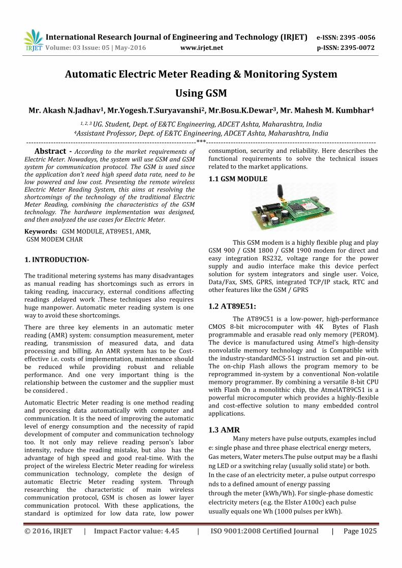
1.1 GSM MODULE
This GSM modem is a highly flexible plug and play GSM 900 / GSM 1800 / GSM 1900 modem for direct and easy integration RS232, voltage range for the power supply and audio interface make this device perfect solution for system integrators and single user. Voice, Data/Fax, SMS, GPRS, integrated TCP/IP stack, RTC and other features like the GSM / GPRS
1.2 AT89E51:
The AT89C51 is a low-power, high-performance CMOS 8-bit microcomputer with 4K Bytes of Flash programmable and erasable read only memory (PEROM). The device is manufactured using Atmel’s high-density nonvolatile memory technology and is Compatible with the industry-standardMCS-51 instruction set and pin-out. The on-chip Flash allows the program memory to be reprogrammed in-system by a conventional Non-volatile memory programmer. By combining a versatile 8-bit CPU with Flash On a monolithic chip, the AtmelAT89C51 is a powerful microcomputer which provides a highly-flexible and cost-effective solution to many embedded control applications.
1.3 AMR Many meters have pulse outputs, examples includ
e: single phase and three phase electrical energy meters,
Gas meters, Water meters.The pulse output may be a flashi
ng LED or a switching relay (usually solid state) or both.
In the case of an electricity meter, a pulse output correspo
nds to a defined amount of energy passing
through the meter (kWh/Wh). For singlephase domestic
electricity meters (e.g. the Elster A100c) each pulse
usually equals one Wh (1000 pulses per kWh).

International Research Journal of Engineering and Technology (IRJET) e-ISSN: 2395 -0056
Volume: 03 Issue: 05 | May-2016 www.irjet.net p-ISSN: 2395-0072
© 2016, IRJET | Impact Factor value: 4.45 | ISO 9001:2008 Certified Journal | Page 1026
1.3 Calculating Energy: For the A100c meter, each pulse represents 1/1000th of a kWh, i.e. 1 Wh, of energy passing through the meter.
1.4 Calculating Power: 3600 seconds per hour = 3600J per pulse i.e. 1 Wh = 3600J therefore, instantaneous power P = 3600 / T where T is the time between the falling edge of each pulse.
What is a pulse?
Introduction to pulse counting | Open Energy Monitor
Figure 1 illustrates a pulse output. The pulse width T_high varies depending on the meter. Some pulse output meters allow T_high to be set. T_high remains constant during operation. For the A100c meter T_high is 50ms. The time between the pulses T_low is what indicates the power measured by the meter. .
1.5.Optical pulse counting: Flashing LEDs Many electricity meters do not have pulse output connections or the connections are not accessible due to restrictions imposed by the utility company. All modern meters have an optical pulse output LED. In such cases an optical sensor can be used to interface with the meter. Pulse output meters are consumption monitoring devices. A pulse output power meter will indicate the number of kWh used by the system load This is calculated by measuring the total consumption at the beginning and end of the data logging period, and evaluating the difference with respect to the interval.
This will allow you to configure the rate field engineering units to either units per minute, or units per hour
2.0 Literature Survey
Reference Paper Study- 2.1. Implementation of Automatic Meter Reading System Using Wireless Sensor Network Our study Survey: traditional meter reading such as errors in reading, inaccuracy, external conditions affecting readings, delayed work we have implemented meter reading system based on latest technology. 2.2. Zig Bee Based Electric Meter Reading System Our study Survey: According to the market requirements of Electric Meter. Nowadays, the system will use GSM system for communication protocol. The ZigBee is used since the application don’t need high speed data rate, need to be low powered and low cost. 2.3. Design and Implementation of Automatic Meter Reading System Using GSM, ZIGBEE through GPRS Our study Survey: The wide proliferation of wireless communication propose and explore new possibilities for the next generation Automatic Meter Reading (AMR) whose goal is to help collect the meter measurement automatically and possibly send commands to the meters. Automation ranges from Connecting to a meter through an RS-232 interface for transmitting the meter measurements all the way from the meter to the utility company via GSM network.
2.4. Design of remote automatic meter reading system based on ZigBee and GPRS Our study Survey: we propose household metering system design based on GSM technologies, using communication function. 3.0 SOFTWARE APPLICATION
Visual Basic .NET (VB.NET) is an object-oriented computer language that can be viewed as an evolution of Microsoft’s Visual Basic (VB) implemented on the Microsoft.NET Framework. Its introduction has been controversial, as significant changes were made that
International Research Journal of Engineering and Technology (IRJET) e-ISSN: 2395 -0056
Volume: 03 Issue: 05 | May-2016 www.irjet.net p-ISSN: 2395-0072
© 2016, IRJET | Impact Factor value: 4.45 | ISO 9001:2008 Certified Journal | Page 1027
broke backward compatibility with VB and caused a rift within the developer community .The great majority of VB.NET developer use Visual Stidio.NET as their integrated development environment (IDE). Program written in VB.NET require the .NET framework execute.
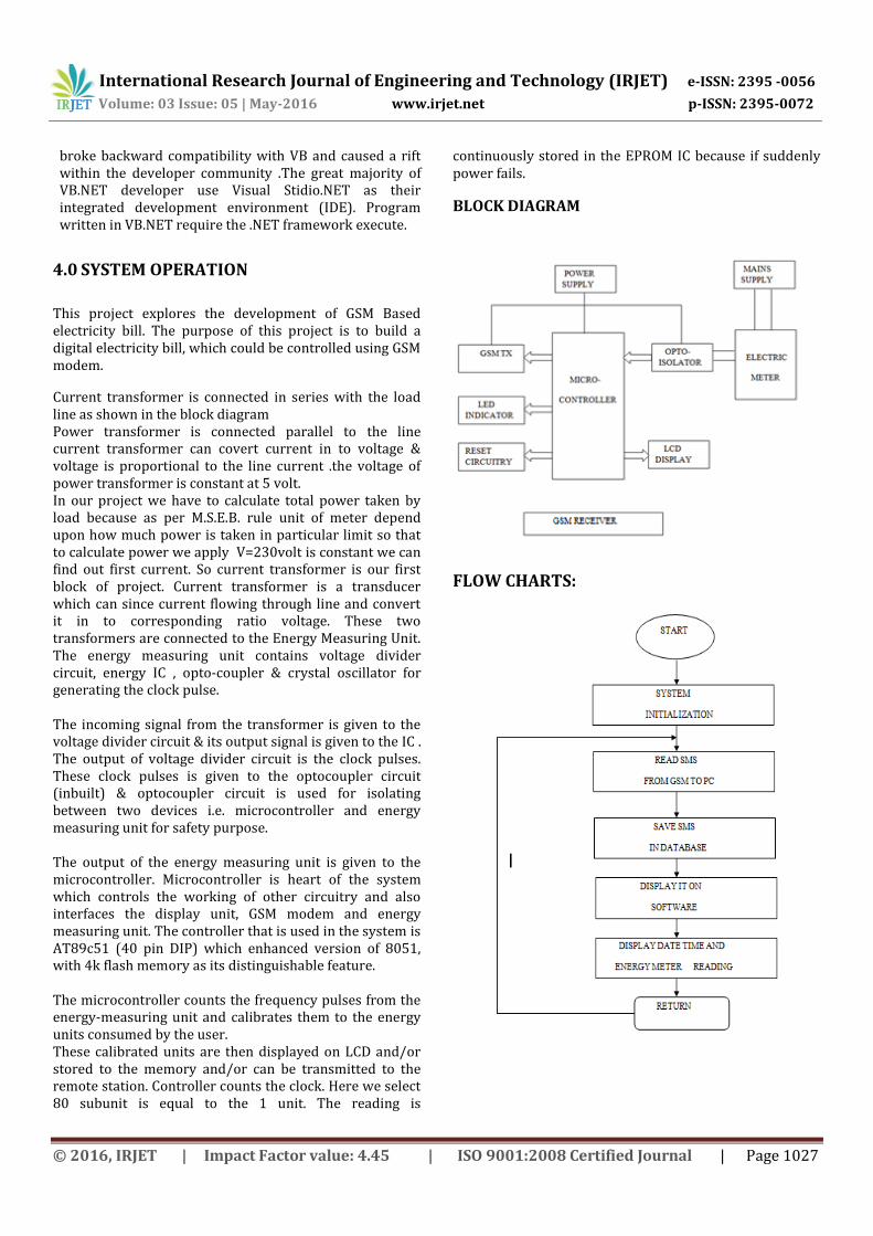
4.0 SYSTEM OPERATION
This project explores the development of GSM Based electricity bill. The purpose of this project is to build a digital electricity bill, which could be controlled using GSM modem.
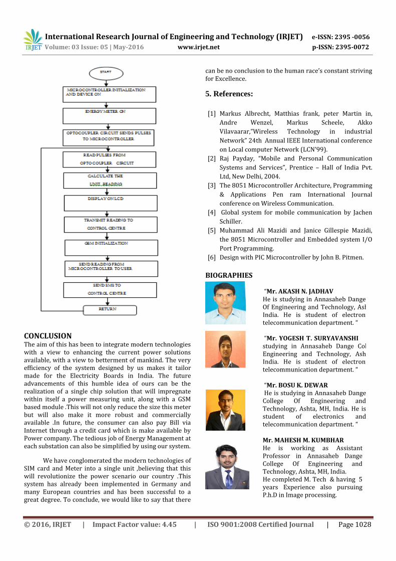
Current transformer is connected in series with the load line as shown in the block diagram Power transformer is connected parallel to the line current transformer can covert current in to voltage & voltage is proportional to the line current .the voltage of power transformer is constant at 5 volt. In our project we have to calculate total power taken by load because as per M.S.E.B. rule unit of meter depend upon how much power is taken in particular limit so that to calculate power we apply V=230volt is constant we can find out first current. So current transformer is our first block of project. Current transformer is a transducer which can since current flowing through line and convert it in to corresponding ratio voltage. These two transformers are connected to the Energy Measuring Unit. The energy measuring unit contains voltage divider circuit, energy IC , opto-coupler & crystal oscillator for generating the clock pulse. The incoming signal from the transformer is given to the voltage divider circuit & its output signal is given to the IC . The output of voltage divider circuit is the clock pulses. These clock pulses is given to the optocoupler circuit (inbuilt) & optocoupler circuit is used for isolating between two devices i.e. microcontroller and energy measuring unit for safety purpose. The output of the energy measuring unit is given to the microcontroller. Microcontroller is heart of the system which controls the working of other circuitry and also interfaces the display unit, GSM modem and energy measuring unit. The controller that is used in the system is AT89c51 (40 pin DIP) which enhanced version of 8051, with 4k flash memory as its distinguishable feature. The microcontroller counts the frequency pulses from the energy-measuring unit and calibrates them to the energy units consumed by the user. These calibrated units are then displayed on LCD and/or stored to the memory and/or can be transmitted to the remote station. Controller counts the clock. Here we select 80 subunit is equal to the 1 unit. The reading is
continuously stored in the EPROM IC because if suddenly power fails.
BLOCK DIAGRAM
FLOW CHARTS:
International Research Journal of Engineering and Technology (IRJET) e-ISSN: 2395 -0056
Volume: 03 Issue: 05 | May-2016 www.irjet.net p-ISSN: 2395-0072
© 2016, IRJET | Impact Factor value: 4.45 | ISO 9001:2008 Certified Journal | Page 1028
CONCLUSION The aim of this has been to integrate modern technologies with a view to enhancing the current power solutions available, with a view to betterment of mankind. The very efficiency of the system designed by us makes it tailor made for the Electricity Boards in India. The future advancements of this humble idea of ours can be the realization of a single chip solution that will impregnate within itself a power measuring unit, along with a GSM based module .This will not only reduce the size this meter but will also make it more robust and commercially available .In future, the consumer can also pay Bill via Internet through a credit card which is make available by Power company. The tedious job of Energy Management at each substation can also be simplified by using our system.
We have conglomerated the modern technologies of SIM card and Meter into a single unit ,believing that this will revolutionize the power scenario our country .This system has already been implemented in Germany and many European countries and has been successful to a great degree. To conclude, we would like to say that there
can be no conclusion to the human race’s constant striving for Excellence.
5. References:
[1] Markus Albrecht, Matthias frank, peter Martin in,
Andre Wenzel, Markus Scheele, Akko
Vilavaarar,”Wireless Technology in industrial
Network” 24th Annual IEEE International conference
on Local computer Network (LCN’99).
[2] Raj Payday, “Mobile and Personal Communication
Systems and Services”, Prentice – Hall of India Pvt.
Ltd, New Delhi, 2004.
[3] The 8051 Microcontroller Architecture, Programming
& Applications Pen ram International Journal
conference on Wireless Communication.
[4] Global system for mobile communication by Jachen
Schiller.
[5] Muhammad Ali Mazidi and Janice Gillespie Mazidi,
the 8051 Microcontroller and Embedded system I/O
Port Programming.
[6] Design with PIC Microcontroller by John B. Pitmen.
BIOGRAPHIES
“Mr. AKASH N. JADHAV He is studying in Annasaheb Dange College Of Engineering and Technology, Ashta, MH, India. He is student of electronics and telecommunication department. “
“Mr. YOGESH T. SURYAVANSHI He is studying in Annasaheb Dange College Of Engineering and Technology, Ashta, MH, India. He is student of electronics and telecommunication department. “
“Mr. BOSU K. DEWAR He is studying in Annasaheb Dange College Of Engineering and Technology, Ashta, MH, India. He is student of electronics and telecommunication department. “
Mr. MAHESH M. KUMBHAR He is working as Assistant Professor in Annasaheb Dange College Of Engineering and Technology, Ashta, MH, India. He completed M. Tech & having 5 years Experience also pursuing P.h.D in Image processing.