Automatic capacitor banks with static system - LPINZ · R4-3 Power factor correction and harmonic...
12
Automatic capacitor banks with static system Unit 6/22 Moselle Ave, Henderson, Auckland, New Zealand PO Box 21-872, Henderson, Auckland, New Zealand Phone:+64 9 833 5749 Email:[email protected] Web: www.LPINZ.co.nz NEW ZEALAND WWW.LPINZ.CO.NZ
Transcript of Automatic capacitor banks with static system - LPINZ · R4-3 Power factor correction and harmonic...

Automatic capacitor banks with static system
Unit 6/22 Moselle Ave, Henderson, Auckland, New Zealand PO Box 21-872, Henderson, Auckland, New Zealand
Phone:+64 9 833 5749Email:[email protected]
Web: www.LPINZ.co.nzNEW ZEALANDWWW.LPINZ.CO.NZ

R4-2
Automatic capacitor banks with static system
Introduction · · · · · · · · · · · · · · · · · · · · · · · · · · · · · · · · · · · · · · · · · · · · · · · · · · · · · · · · · · · · · · · · · · · · · · · · · · · · · · · · · · · · · · · · · · · R4-3
R.4 - Automatic capacitor banks with static system
Selection table · · · · · · · · · · · · · · · · · · · · · · · · · · · · · · · · · · · · · · · · · · · · · · · · · · · · · · · · · · · · · · · · · · · · · · · · · · · · · · · · · · · · · · · · · R4-4
ECK / EMKAutomatic capacitor banks with static system · · · · · · · · · · · · · · · · · · · · · · · · · · · · · · · · · · · · · · · · · · · · · · · · · · · · · · · · · · · · · · · · · · · · · R4-5
PLUS Entelligent automatic capacitor banks with static system · · · · · · · · · · · · · · · · · · · · · · · · · · · · · · · · · · · · · · · · · · · · · · · · · · · · · · · · · · · · · R4-7
EMB / EMFStatic switching units (three-phase) · · · · · · · · · · · · · · · · · · · · · · · · · · · · · · · · · · · · · · · · · · · · · · · · · · · · · · · · · · · · · · · · · · · · · · · · · · · · · R4-9
CPC3Zero step control board · · · · · · · · · · · · · · · · · · · · · · · · · · · · · · · · · · · · · · · · · · · · · · · · · · · · · · · · · · · · · · · · · · · · · · · · · · · · · · · · · · · · · R4-11

R4-3
Power factor correction and harmonic filtering
Automatic capacitor banks with static system
R.4
CIRCUTOR solutions for reactive power
Instant response not required
Instant response becouse of the fast variation
by the receiver
Lowmaintenance (absence of
moving parts)
Capacitor banks with thyristors
Capacitor banks with contactors
Automatic capacitor banks with stat-ic system - E Series
The E Series capacitor banks with static system have been designed for Power factor correction purposes in networks with fluctuating loads.
The variations in power are relatively fast (in milliseconds) so that the switch-ing operations are carried out by thyris-tors, which are connected to a voltage control board, so that the connection and disconnection of the capacitor is carried out with a zero voltage difference.
Transients are prevented between the connection and disconnection of steps, obtaining the immediate response to the load fluctuations.
Functions and advantages of capaci-tor banks with a static system
The functions or advantages of this compensation system are as follows:
}} Immediate response to the compen-sation request. The response time of the Power factor correction can be of a single network frequency cycle, thus achieving an almost instantaneous compensation.
}} Elimination of start-up transients pro-duced by the capacitor's connection. The connection takes place when the voltage network matches that of the capacitor when it is partially or totally loaded, as seen Fig.1.
Fig. 1
}} The lack of transients in the connec-tion allows us to eliminate gaps, flicker and any other alteration generated by the connection's transient.
}} Limited switching operations
}} Lower wear of capacitors and swit-ching elements, due to the elimination of transients and the total absence of mobile mechanical parts. This is how we can greatly increase the working life of the unit, as compared to conventional electromechanical contactor units.
Connection of a static capacitor bank
Static capacitor banks are usually con-nected to the general switchboard or secondary switchboards in the case of large-scale installations.
Classification of the static system, depending on the compensation method
Static compensation systems are as fol-lows, as in the case of capacitor banks:
}} Fixed static systems - the most com-mon application is in individual units that require a quick compensation response (for ex., welding equipment). EMB/ EMF Series.
}} Automatic static system. For the monitoring of variable loads. ECK / EMK Series.

Automatic capacitor banks with static system
R4-4
Product selection table
Equipment Compensation Level of harmonics in the installation Scope Page
EMS
/ EM
K
AutomaticLow
THD(I) ≤ 15%THD(U) ≤ 2.5%
Up to 100 kvar: ECKUp to 400 kvar: EMK4Up to 600 kvar: EMK6Up to 800 kvar: EMK8Up to 1200 kvar: EMK12
5
EMF Individual
(Static module with fuse protection)
LowTHD(I) ≤ 15%
THD(U) ≤ 2.5%
25 to 45 kvar (230 V)
40 to 80 kvar (400 V)9
EMB Individual
(Static module with terminal connection. No protection)
LowTHD(I) ≤ 15%
THD(U) ≤ 2.5%
25 to 45 kvar (230 V)
40 to 80 kvar (400 V)9
PLU
S EC
/E
AutomaticLow
THD(I) ≤ 15%THD(U) ≤ 2.5%
Up to 100 kvar: PLUS ECUp to 400 kvar: PLUS E4Up to 600 kvar: PLUS E6Up to 800 kvar: PLUS E8Up to 1200 kvar: PLUS E12
7
see
R6
AutomaticHigh
THD(I) ≥ 15%THD(U) ≥ 2.5%
R6
CPC
3
11

Automatic capacitor banks with static system
R4-5
Automatic capacitor banks with static systemECK / EMK
The E Series capacitor banks have been designed for Power factor correction purposes in networks with fluctuating loads.
The variations in power are relatively fast (in milliseconds) so that the switching operations are carried out by thyristors, which are connected to a voltage control board, so that the connection and disconnection of the capacitor is carried out with a zero voltage difference.
Transients are prevented between the connection and disconnection of steps, obtaining the immediate response to the load fluctuations.
Application
The most common application is with indi-vidual loads or in installations where a quick compensation response is needed (for ex., welding units, motors for lifting units, lifts, etc.)
FeaturesDescription
FeaturesOperating voltage 230, 400 V (for other voltages, please ask)Support voltage 440 V (400 V)Capacity tolerance ± 10%
Unit composed of
• CS capacitor. Three-phase measurement • Static switching unit on each step, composed of static contactors (thyristors) • Individual protection of each step with high rupture power
(HRP). NH-00 or Neozed series, depending on the type • Two-pole earth leakage protection system for regulator
and capacitor bank switching operations • Power factor regulator of the computer df series • Heat removal radiators • Built-in thermostat on the radiator for the disconnection of each step in case of high temperatures (90 ºC).
Add-ons
• Manual capacitor bank header switch • Automatic capacitor bank header switch • Automatic switch + Earth leakage protection at the capacitor bank's header • Forced ventilation unit + thermostat • Polycarbonate board to protect against direct contacts • Auto-transformer 400/230 V
Insulation level 3 / 15 kVDischarge resistance 75 V / 3 minutesOverload 1.3 times the nominal hold current
Overvoltage
• 10 % 8 over 24 hours • 15 % up to 15 minutes over 24 hours • 20 % up to 5 minutes over 24 hours • 30 % up to 1 minutes over 24 hours
Switching voltage 400 VAmbient conditions
Class D temperature
Daily meanAnnual meanMaximumMinimum
45 ºC35 ºC50 ºC-25 ºC
Humidity 80% RHAltitude 2,000 mConstruction featuresDegree of protection IP 21
Colour RAL 7035 GreyRAL 3005 Maroon
Assembly conditionsType of assembly VerticalVentilation Natural or forced, depending on the optionDistance between capacitors Minimum, 2 cmStandardsCEI 60831-1, CEI 70/7, UNE 20827, UNE 20010, BS 1650, VDE 560
Automatic capacitor banks with static system
R4-6
References
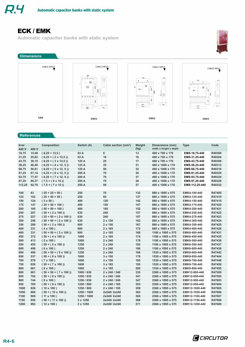
Dimensions
Automatic capacitor banks with static systemECK / EMK
kvar Composition Switch (A) Cable section (mm2) Weight (kg)
Dimensions (mm) width x height x depth
Type Code440 V 400 V18,75 15,49 ( 6,25 + 12,5 ) 63 A 6 13 400 x 700 x 170 EMS-18,75-440 R4930031,25 25,82 ( 6,25 + ( 2 x 12,5 )) 63 A 16 16 400 x 700 x 170 EMS-31,25-440 R4930443,75 36,15 ( 6,25 + ( 3 x 12,5 )) 125 A 25 17 400 x 700 x 170 EMS-43,75-440 R4930856,25 46,48 ( 6,25 + ( 4 x 12, 5 )) 125 A 35 31 400 x 1006 x 170 EMS-56,25-440 R4931268,75 56,81 ( 6,25 + ( 5 x 12, 5 )) 125 A 50 32 400 x 1006 x 170 EMS-68,75-440 R4931681,25 67,14 ( 6,25 + ( 6 x 12, 5 )) 200 A 70 36 400 x 1006 x 170 EMS-81,25-440 R4932093,75 77,47 ( 6,25 + ( 7 x 12, 5 )) 200 A 70 37 400 x 1006 x 170 EMS-93,75-440 R4932497,25 80,37 ( 7,5 + ( 6 x 15 )) 200 A 70 36 400 x 1006 x 170 EMS-97,25-440 R49328112,25 92,76 ( 7,5 + ( 7 x 15 )) 250 A 95 37 400 x 1006 x 170 EMS-112,25-440 R49332
100 83 ( 25 + 25 + 50 ) 250 70 132 880 x 1895 x 575 EMK4-100-440 R47405125 103 ( 25 + 50 + 50 ) 250 95 137 880 x 1895 x 575 EMK4-125-440 R47410150 124 ( 3 x 50 ) 400 120 142 880 x 1895 x 575 EMK4-150-440 R47415175 147 ( 25 + 50 + 100 ) 400 150 147 880 x 1895 x 575 EMK4-175-440 R47420200 165 ( 50 + 50 + 100 ) 400 185 152 880 x 1895 x 575 EMK4-200-440 R47421250 207 ( 50 + ( 2 x 100 )) 630 240 157 880 x 1895 x 575 EMK4-250-440 R47422275 227 ( 25 + 50 + ( 2 x 100 )) 630 240 157 880 x 1895 x 575 EMK4-275-440 R47423300 248 ( 50 + 50 + ( 2 x 100 )) 630 2 x 120 162 880 x 1895 x 575 EMK4-300-440 R47424350 289 ( 50 + ( 3 x 100 )) 800 2 x 150 167 880 x 1895 x 575 EMK4-350-440 R47425400 331 ( 4 x 100 ) 800 2 x 185 172 880 x 1895 x 575 EMK4-400-440 R47426400 331 ( 50 + 50 + ( 3 x 100 )) 800 2 x 185 168 1180 x 1895 x 575 EMK6-400-440 R47431450 372 ( 50 + ( 4 x 100 )) 1000 2 x 185 174 1180 x 1895 x 575 EMK6-450-440 R47435500 413 ( 5 x 100 ) 1000 2 x 240 178 1180 x 1895 x 575 EMK6-500-440 R47436550 455 ( 50 + ( 5 x 100 )) 1250 2 x 240 182 1180 x 1895 x 575 EMK6-550-440 R47437600 496 ( 6 x 100 ) 1250 2 x 240 186 1180 x 1895 x 575 EMK6-600-440 R47438600 496 ( 50 + 50 + ( 5 x 100 )) 1250 2 x 240 168 1530 x 1895 x 575 EMK8-600-440 R47442650 537 ( 50 + ( 6 x 100 )) 1600 3 x 150 179 1530 x 1895 x 575 EMK8-650-440 R47444700 579 ( 7 x 100 ) 1600 3 x 150 185 1530 x 1895 x 575 EMK8-700-440 R47448750 620 ( 50 + ( 7 x 100 )) 1600 3 x 185 195 1530 x 1895 x 575 EMK8-750-440 R47450800 661 ( 8 x 100 ) 1600 3 x 185 200 1530 x 1895 x 575 EMK8-800-440 R47455800 661 ( 50 + 50 + ( 7 x 100 )) 1000 / 630 2 x 240 / 240 335 2360 x 1895 x 575 EMK12-800-440 R47500850 702 ( 50 + ( 8 x 100 )) 1250 / 630 2 x 240 / 240 341 2360 x 1895 x 575 EMK12-850-440 R47505900 744 ( 9 x 100 ) 1250 / 630 2 x 240 / 240 347 2360 x 1895 x 575 EMK12-900-440 R47603950 785 ( 50 + ( 9 x 100 )) 1250 / 800 2 x 240 / 185 353 2360 x 1895 x 575 EMK12-950-440 R476041000 826 ( 10 x 100 ) 1250 / 800 2 x 240 / 185 359 2360 x 1895 x 575 EMK12-1000-440 R476051050 868 ( 50 + ( 10 x 100 )) 1250 / 1000 2x240/ 2x240 362 2360 x 1895 x 575 EMK12-1050-440 R476061100 909 ( 11 x 100 ) 1250 / 1000 2x240/ 2x240 365 2360 x 1895 x 575 EMK12-1100-440 R476071150 950 ( 50 + ( 11 x 100 )) 2 x 1250 2x240/ 2x240 368 2360 x 1895 x 575 EMK12-1150-440 R476081200 992 ( 12 x 100 ) 2 x 1250 2x240/ 2x240 371 2360 x 1895 x 575 EMK12-1200-440 R47609
EMK4
1805
CABLE INPUT
EMS
CABLE INPUT
EMK6
1805
CABLE INPUT
EMK8
1805
CABLE INPUT

Automatic capacitor banks with static system
R4-7
Automatic capacitor banks with static systemPLUS E
State-of-the-art intelligent capacitor banks that are capable of measuring the three in-stallation phases and compensating the pow-er factor consumption of each phase in real time. In addition, they correct the total zero power factor and balance the active power in each phase.
The PLUS E Power factor correction unit has been designed with CIRCUTOR's measure-ment system technology, effectively creating a compensation + measurement unit. As a power quality analyzer, it displays any electri-cal parameter of the network in real time and records it in its internal memory, with maxi-mum and minimum values, date and hour.
Application
Plus capacitor banks are ideal to compen-sate modern installations that often have unbalanced loads. Its three-phase measure-ment system, phase-by-phase compensation and power analyzer functions make it the ide-al solution to compensate installations with a variation of quick loads, between 20 ms and 4 s, and/or large unbalances between phases, such as welding units, cranes, lifts and lifting units, smelters, hospitals, automotive indus-try or any other sector or unit that requires an efficient compensation of the power factor.
FeaturesDescription
FeaturesOperating voltage 230, 400 V (for other voltages, please ask)Support voltage 440 V (400 V)Capacity tolerance ± 10%
Unit composed of
• CS capacitor. Three-phase measurement • Static switching unit on each step, composed of static
contactors (thyristors). Power analyzer function. • Individual protection of each step with high rupture power
(HRP). NH-00 or Neozed series, depending on the type • Two-pole earth leakage protection system for regulator
and capacitor bank switching operations • Power factor regulator of the computer Plus series, three-phase measurement and power quality analyzer function
• Heat removal radiators Built-in thermostat on the radiator for the disconnection of each step in case of high temperatures (90 ºC).
Add-ons
• Manual capacitor bank header switch • Automatic capacitor bank header switch • Automatic switch + Earth leakage protection at the capacitor bank's header • Forced ventilation unit + thermostat • Polycarbonate board to protect against direct contacts • Auto-transformer 400/230 V
Insulation level 3 / 15 kV
Discharge resistance 75 V / 3 minutesOverload 1.3 times the nominal hold current
Overvoltage
• 10 % 8 over 24 hours • 15 % up to 15 minutes over 24 hours • 20 % up to 5 minutes over 24 hours • 30 % up to 1 minutes over 24 hours
Switching voltage 400 V
Ambient conditions
Class D temperature
Daily meanAnnual meanMaximumMinimum
45 ºC35 ºC50 ºC-25 ºC
Humidity 80% RHAltitude 2,000 mConstruction featuresDegree of protection IP 21
Colour RAL 7035 GreyRAL 3005 Maroon
Assembly conditionsType of assembly VerticalVentilation Natural or forced, depending on the optionDistance between capacitors Minimum, 2 cmStandardsCEI 60831-1, CEI 70/7, UNE 20827, UNE 20010, BS 1650, VDE 560

Automatic capacitor banks with static system
R4-8
References
Dimensions
Automatic capacitor banks with static systemPLUS E
PLUS E4
1805
CABLE INPUT
PLUS EC
CABLE INPUT
PLUS E6
1805
CABLE INPUT
PLUS E8
1805
CABLE INPUT
kvar Composition Switch (A) Cable section (mm2)
Weight (kg)
Dimensions (mm) width x height x depth
Type Code440 V 400 V7,5 6,2 ( 2,5 + 5 ) 63 6 44 532 x 930 x 235 PLUS EC-7.5-440 R4830012,5 10 ( 2,5 + 5 + 5 ) 63 6 50 532 x 930 x 235 PLUS EC-12.5-440 R4830217,5 14 ( 2,5 + 5 + 10 ) 63 16 51 532 x 930 x 235 PLUS EC-17.5-440 R4830425 21 ( 5 + ( 2 x 10 )) 100 16 52 532 x 930 x 235 PLUS EC-25-440 R4830635 29 ( 5 + 10 + 20 ) 100 25 54 532 x 930 x 235 PLUS EC-35-440 R4830843,75 36 ( 6.25 + ( 3 x 12.5 )) 160 25 55 532 x 930 x 235 PLUS EC-43.75-440 R4831050 41 ( 10 + ( 2 x 20 )) 160 35 56 532 x 930 x 235 PLUS EC-50-440 R4831255 45 ( 5 + 10 + ( 2 x 20 )) 160 35 57 532 x 930 x 235 PLUS EC-55-440 R4831460 50 ( 3 x 20 ) 160 50 59 532 x 930 x 235 PLUS EC-60-440 R4831670 58 ( 10 + ( 3 x 20 )) 160 70 59 532 x 930 x 235 PLUS EC-70-440 R4831875 62 ( 3 x 25 ) 250 70 60 532 x 930 x 235 PLUS EC-75-440 R4832080 66 ( 4 x 20 ) 250 70 61 532 x 930 x 235 PLUS EC-80-440 R4832287,5 72 ( 12.5 + ( 3 x 25 )) 250 70 62 532 x 930 x 235 PLUS EC-87.5-440 R48324100 83 ( 4 x 25 ) 250 70 63 532 x 930 x 235 PLUS EC-100-440 R48326100 83 ( 25 + 25 + 50 ) 250 70 132 880 x 1895 x 575 PLUS E4-100-440 R48405125 103 ( 25 + 50 + 50 ) 250 95 137 880 x 1895 x 575 PLUS E4-125-440 R48410150 124 ( 3 x 50 ) 400 120 142 880 x 1895 x 575 PLUS E4-150-440 R48415175 147 ( 25 + 50 + 100 ) 400 150 147 880 x 1895 x 575 PLUS E4-175-440 R48420200 165 ( 50 + 50 + 100 ) 400 185 152 880 x 1895 x 575 PLUS E4-200-440 R48421250 207 ( 50 + ( 2 x 100 )) 630 240 157 880 x 1895 x 575 PLUS E4-250-440 R48422275 227 ( 25 + 50 + ( 2 x 100 )) 630 240 157 880 x 1895 x 575 PLUS E4-275-440 R48423300 248 ( 50 + 50 + ( 2 x 100 )) 630 2 x 120 162 880 x 1895 x 575 PLUS E4-300-440 R48424350 289 ( 50 + ( 3 x 100 )) 800 2 x 150 167 880 x 1895 x 575 PLUS E4-350-440 R48425400 331 ( 4 x 100 ) 800 2 x 185 172 880 x 1895 x 575 PLUS E4-400-440 R48426400 331 ( 50 + 50 + ( 3 x 100 )) 800 2 x 185 168 1180 x 1895 x 575 PLUS E6-400-440 R48431450 372 ( 50 + ( 4 x 100 )) 1000 2 x 185 174 1180 x 1895 x 575 PLUS E6-450-440 R48435500 413 ( 5 x 100 ) 1000 2 x 240 178 1180 x 1895 x 575 PLUS E6-500-440 R48436550 455 ( 50 + ( 5 x 100 )) 1250 2 x 240 182 1180 x 1895 x 575 PLUS E6-550-440 R48437600 496 ( 6 x 100 ) 1250 2 x 240 186 1180 x 1895 x 575 PLUS E6-600-440 R48438600 496 ( 50 + 50 + ( 5 x 100 )) 1250 2 x 240 168 1530 x 1895 x 575 PLUS E8-600-440 R48442650 537 ( 50 + ( 6 x 100 )) 1600 3 x 150 179 1530 x 1895 x 575 PLUS E8-650-440 R48444700 579 ( 7 x 100 ) 1600 3 x 150 185 1530 x 1895 x 575 PLUS E8-700-440 R48448750 620 ( 50 + ( 7 x 100 )) 1600 3 x 185 195 1530 x 1895 x 575 PLUS E8-750-440 R48450800 661 ( 8 x 100 ) 1600 3 x 185 200 1530 x 1895 x 575 PLUS E8-800-440 R48455800 661 ( 50 + 50 + ( 7 x 100 )) 1000 / 630 2 x 240 / 240 335 2360 x 1895 x 575 PLUS E12-800-440 R48500850 702 ( 50 + ( 8 x 100 )) 1250 / 630 2 x 240 / 240 341 2360 x 1895 x 575 PLUS E12-850-440 R48505900 744 ( 9 x 100 ) 1250 / 630 2 x 240 / 240 347 2360 x 1895 x 575 PLUS E12-900-440 R48603950 785 ( 50 + ( 9 x 100 )) 1250 / 800 2 x 240 / 185 353 2360 x 1895 x 575 PLUS E12-950-440 R486041000 826 ( 10 x 100 ) 1250 / 800 2 x 240 / 185 359 2360 x 1895 x 575 PLUS E12-1000-440 R486051050 868 ( 50 + ( 10 x 100 )) 1250 / 1000 2x240/ 2x240 362 2360 x 1895 x 575 PLUS E12-1050-440 R486061100 909 ( 11 x 100 ) 1250 / 1000 2x240/ 2x240 365 2360 x 1895 x 575 PLUS E12-1100-440 R486071150 950 ( 50 + ( 11 x 100 )) 2 x 1250 2x240/ 2x240 368 2360 x 1895 x 575 PLUS E12-1150-440 R486081200 992 ( 12 x 100 ) 2 x 1250 2x240/ 2x240 371 2360 x 1895 x 575 PLUS E12-1200-440 R48609

Automatic capacitor banks with static system
R4-9
Static switching units (three-phase)EMB / EMF
The static switching modules of the EM Se-ries are the basic building block for the con-struction of static capacitor banks for Power factor correction purposes.
These capacitor banks use thyristors instead of the classic contactors for the connection of each large group of capacitors and they are ideal in installations where the leakage cur-rent suffers quick and large fluctuations (load changes in intervals that can range from split seconds to 8 or 10 seconds).
Application
The static switching units of the EM Series have been designed to connect and discon-nect capacitors in milliseconds.
They can be used to build capacitors with various steps, or for the individual compen-sation of a load that must be compensated instantly due to connection / disconnection deficiencies, for example, in welding units, cranes, lifts, etc.
FeaturesDescription
Features
Standard voltages 230, 400 V a.c. (other voltages up to 660 V a.c., please ask)
Frequency 50 / 60 Hz
Nominal switched power See table with types
Overload capacity 1.5 In during 1 min
Protections
Fuses NH adapted to the gauge (type EMF)
du / dt RC protection at 1000 V/μs
Thermostat 90 ºC
di / dt 100 A/μs (L=12 μH, not included, it must be installed in series with the capacitor)
Ambient conditions
Maximum ambient temperature 40 ºC
Maximum temperature of the dissipator 80 ºCConstruction featuresDegree of protection IP 00Weight 10.5 kgStandardsEN 60.439 (IEC 439, UNE EN 60439), IEC 146, CSA 22.2 No. 14

Automatic capacitor banks with static system
R4-10
References
Dimensions
Static switching units (three-phase)EMB / EMF
With fuses
kvar Weight (kg) Dimensions (mm) width x height x depth
Type Code
25 10,5 177 X 485 X 268 EMF-25/230 R41111
37,5 10,5 177 X 485 X 268 EMF-37.5/230 R41112
45 10,5 177 X 485 X 268 EMF-45/230 R41114
40 10,5 177 X 485 X 268 EMF-40/400 R41133
60 10,5 177 X 485 X 268 EMF-60/400 R41136
80 10,5 177 X 485 X 268 EMF-80/400 R41137
With terminals
kvar Weight (kg) Dimensions (mm) width x height x depth
Type Code
25 10 177 X 485 X 268 EMB-25/230 R41211
37,5 10 177 X 485 X 268 EMB-37.5230 R41212
45 10 177 X 485 X 268 EMB-45/230 R41214
40 10 177 X 485 X 268 EMB-40/400 R41233
60 10 177 X 485 X 268 EMB-60/400 R41236
80 10 177 X 485 X 268 EMB-80/400 R41237
268177
270
485
159

Automatic capacitor banks with static system
R4-11
Zero step control boardCPC3
Controls the connection of thyristors to the zero voltage step, thus avoiding any transient and enabling various switching operations in one second.
Application
The CPC3i control boards used for the quick connection of capacitors can be used for the connection and disconnection of capacitors in a network cycle, as well as the individual compensation of the power factor consump-tion in each phase.
FeaturesDescription
Features
Power supply 230 / 400 / 690 V (depending on the type)
Insulation level 3 / 15 kVWorking voltage 230 / 400 / 690 V (depending on the type)Frequency 50 / 60 HzDegree of protection IP 00
Ambient conditions
Maximum ambient temperature 40 ºC
Assembly conditions
Static switch controlVoltage-free contactRS-485 Communications (RS Type)
References
V Control Type Code
230 / 400 Three-phase CPC3b R4Z111
230 / 400 Three-phase CPC3i-4T R4Z661
230 / 400 Phase-Phase, by communications CPC3i-4RS R4Z662
230 / 400 Phase-Phase, by static relays CPC3i-4F R4Z663
690 Three-phase CPC3i-6T R4Z664
690 Phase-Phase, by communications CPC3i-6RS R4Z665
690 Phase-Phase, by static relays CPC3i-6F R4Z666
Dimensions
230
110

Automatic capacitor banks with static system
CIRCUTOR, SA reserves the right to change any of the information contained in this catalogue.
CIRCUTOR, SA - Vial Sant Jordi, s/n 08232 Viladecavalls (Barcelona) España Tel. (+34) 93 745 29 00 - Fax: (+34) 93 745 29 14 [email protected]
www.circutor.com Des
ign
ed b
y: C
om
un
icat
ion
& im
age
dp
t o
f C
IRC
UT
OR
, SA
+ information: [email protected]