AUTO-DARKENING HELMET March, 2011 - The … INFORMATION This Auto-Darkening Welding Helmet will...
12
• Sales and Service through Subsidiaries and Distributors Worldwide • Cleveland, Ohio 44117-1199 U.S.A. TEL: 216.481.8100 FAX: 216.486.1751 WEB SITE: www.lincolnelectric.com • World's Leader in Welding and Cutting Products • AUTO-DARKENING HELMET OPERATORʼS MANUAL IM10055 March, 2011 Copyright © Lincoln Global Inc. GRAPHICS MAY VARY
-
Upload
duongquynh -
Category
Documents
-
view
223 -
download
4
Transcript of AUTO-DARKENING HELMET March, 2011 - The … INFORMATION This Auto-Darkening Welding Helmet will...
• Sales and Service through Subsidiaries and Distributors Worldwide •
Cleveland, Ohio 44117-1199 U.S.A. TEL: 216.481.8100 FAX: 216.486.1751 WEB SITE: www.lincolnelectric.com
• World's Leader in Welding and Cutting Products •
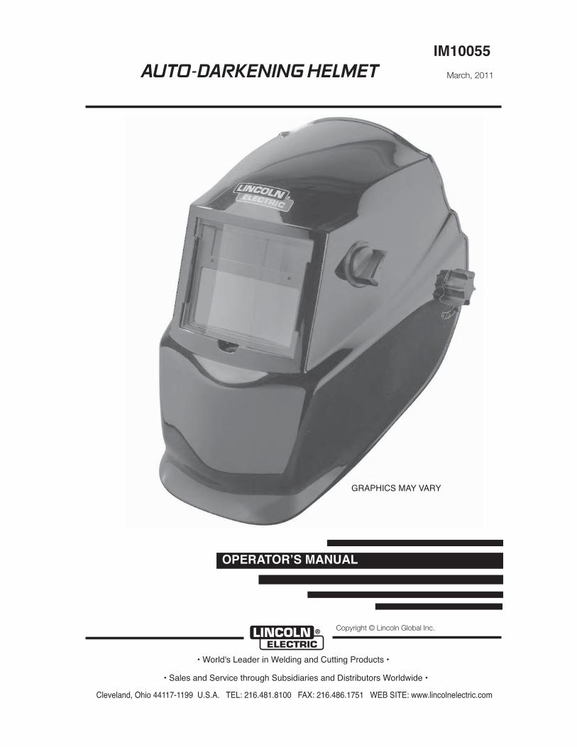
AUTO-DARKENING HELMET
OPERATORʼS MANUAL
IM10055
March, 2011
Copyright © Lincoln Global Inc.
GRAPHICS MAY VARY
TABLE OF CONTENTS Page
SAFETY WARNINGS – READ BEFORE USING 1
HELMET INFORMATION 2
SPECIFICATIONS 3
OPERATING INSTRUCTIONS 4
CARTRIDGE OPERATIONS/FEATURES 5
SHADE GUIDE SETTINGS 6
HELMET CARE AND MAINTENANCE 7
TROUBLE SHOOTING 8
WARRANTY INFORMATION 9
REPLACEMENT PARTS 9
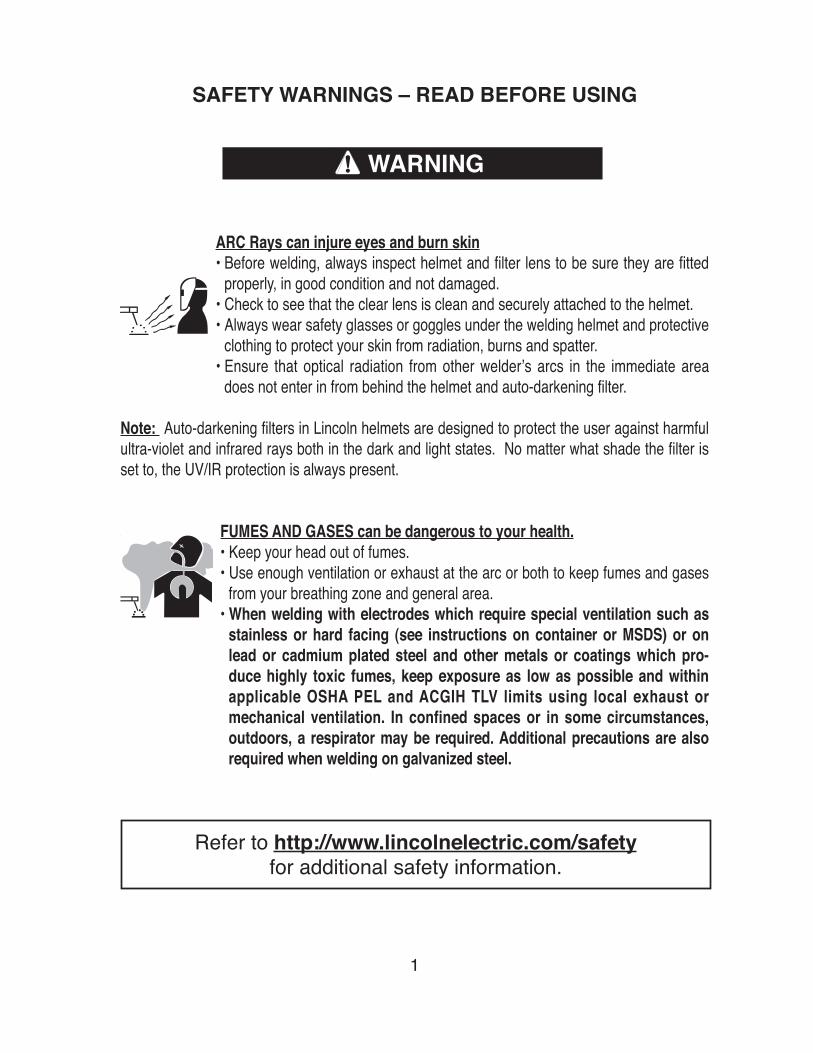
SAFETY WARNINGS – READ BEFORE USING
ARC Rays can injure eyes and burn skin• Before welding, always inspect helmet and filter lens to be sure they are fitted
properly, in good condition and not damaged.• Check to see that the clear lens is clean and securely attached to the helmet.• Always wear safety glasses or goggles under the welding helmet and protective
clothing to protect your skin from radiation, burns and spatter.• Ensure that optical radiation from other welderʼs arcs in the immediate area
does not enter in from behind the helmet and auto-darkening filter.
Note: Auto-darkening filters in Lincoln helmets are designed to protect the user against harmfulultra-violet and infrared rays both in the dark and light states. No matter what shade the filter isset to, the UV/IR protection is always present.
FUMES AND GASES can be dangerous to your health.• Keep your head out of fumes.• Use enough ventilation or exhaust at the arc or both to keep fumes and gases
from your breathing zone and general area.• When welding with electrodes which require special ventilation such as
stainless or hard facing (see instructions on container or MSDS) or onlead or cadmium plated steel and other metals or coatings which pro-duce highly toxic fumes, keep exposure as low as possible and withinapplicable OSHA PEL and ACGIH TLV limits using local exhaust ormechanical ventilation. In confined spaces or in some circumstances,outdoors, a respirator may be required. Additional precautions are alsorequired when welding on galvanized steel.
1
WARNING
Refer to http://www.lincolnelectric.com/safetyfor additional safety information.

HELMET INFORMATION
This Auto-Darkening Welding Helmet will automatically change from a lightstate (shade 3.5) to a dark state (Shade 9-13) when arc welding starts.
The filter automatically returns to a light state when the arc stops.Shade control adjustments can be made while welding.
Match your welding application to the shade indicated on the shade chart.(See Page 6)
• Operating temperature: 14°F ~ 131°F (-10°C ~ 55°C).• Do not use or open the auto-darkening filter if damaged by shock, vibra-
tion or pressure.• Keep the sensors and solar cell clean. Clean the filter cartridge using a
soapy water solution and soft cloth which should be damp but not saturat-ed.
This Auto-Darkening Welding Helmet is designed for use with GMAW, GTAW,MMAW welding, or Plasma Arc and air carbon arc cutting.
The cartridge provides protection from harmful UV and IR radiation, in bothdark and light states.
The cartridge contains two sensors to detect the light from the welding arc,resulting in the lens darkening to a selected welding shade.
• Do not use solvents or abrasive cleaning detergent.• If cover lens is spattered or covered with dirt, it should be replaced imme-
diately.• Use only replacement parts specified in this manual.• Do not use the helmet without inside and outside cover lenses properly
installed.
2

SPECIFICATIONS
3
LCD Viewing Area
Cartridge size
UV/IR Protection
Arc Sensors
Light State Shade
Variable Welding Shades
Shade Control
Power Supply
Power On/Off
Light to Dark Switching Time
Sensitivity Control
Delay Control (Dark to Light)
TIG Rating
Operating Temperature
Storage Temperature
Total Weight
Compliance(1)
97 x 44mm (3.82 x 1.73in)
110 x 90mm (4.33 x 3.54in)
Up to Shade DIN 16 at all times
2
DIN 4
DIN 9 to 13
External knob - full adjustment
Solar cells - no battery required
Fully automatic
0.00004 sec (1/25,000 sec)
High (normal) and Low (extreme ambient light)
(0.25~0.35s <fast>) (0.60~0.80s<slow>)
10 amps
14°F ~ 131°F (-10°C ~ 55°C)
-4°F ~ 158°F (-20°C ~ 70°C)
440g (15.5 Oz.)
DIN-Geprüft, CE,ANSI Z87.1-2003, CSA Z94.3
(1) Headgear compliance with ANSI Z87.1 is without sweatband installed.

OPERATING INSTRUCTIONS
Headgear Adjustment
Head Size Adjustment: Headband tightness is adjusted by pushing in theratchet knob and turning to adjust to desired comfort level. This knob islocated at the back of the helmet. HEAD GEAR CROWN ADJUSTMENT ismade by adjusting crown strap for vertical placement on the head and snap-ping the pin into the hole to lock securely in place.
Tilt: Tilt is adjusted on the left side of the helmet. TILT is adjusted by loos-ening outside tension knob and releasing the adjustment lever from its cur-rent location and moving it to another location. Retighten the outside tensionknob when finished.
4
CROWNADJUSTMENT
TILT ADJUSTMENT
RATCHET KNOB
PIN HOLES FORADJUSTMENT
CROWNADJUSTMENT
TILT ADJUSTMENT
RATCHET KNOB
PIN HOLES FORADJUSTMENT
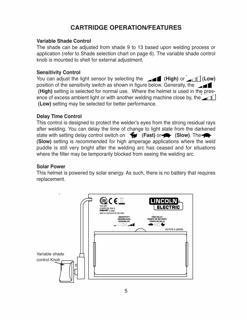
CARTRIDGE OPERATION/FEATURES
Variable Shade ControlThe shade can be adjusted from shade 9 to 13 based upon welding process orapplication (refer to Shade selection chart on page 6). The variable shade controlknob is mounted to shell for external adjustment.
Sensitivity ControlYou can adjust the light sensor by selecting the (High) or (Low)position of the sensitivity switch as shown in figure below. Generally, the(High) setting is selected for normal use. Where the helmet is used in the pres-
ence of excess ambient light or with another welding machine close by, the (Low) setting may be selected for better performance.
Delay Time ControlThis control is designed to protect the welderʼs eyes from the strong residual raysafter welding. You can delay the time of change to light state from the darkenedstate with setting delay control switch on (Fast) or (Slow). The(Slow) setting is recommended for high amperage applications where the weldpuddle is still very bright after the welding arc has ceased and for situationswhere the filter may be temporarily blocked from seeing the welding arc.
Solar PowerThis helmet is powered by solar energy. As such, there is no battery that requiresreplacement.
Variable shade control Knob
5
S272797878-5 ((600600S)
®4/9-9-1313 11/2/1/2/37379 CCE DDINTM ZZ87CAN/C/CSASA ZZ9494.3LLAABBSS SESENSIBILITESESENSIBILIDADSESENSITIVITY TEMPSPS DDE DDELAITIEMPO DDE RRETARDOTIME DDELAY
S272797878-5 ((600600S)
®
4/9-9-1313 11/2/1/2/37379 CCE DDIN
TM ZZ87CAN/C/CSASA ZZ9494.3
LABS
SESENSIBILITESESENSIBILIDADSESENSITIVITY
TEMPSPS DDE DDELAITIEMPO DDE RRETARDO
TIME DDELAY
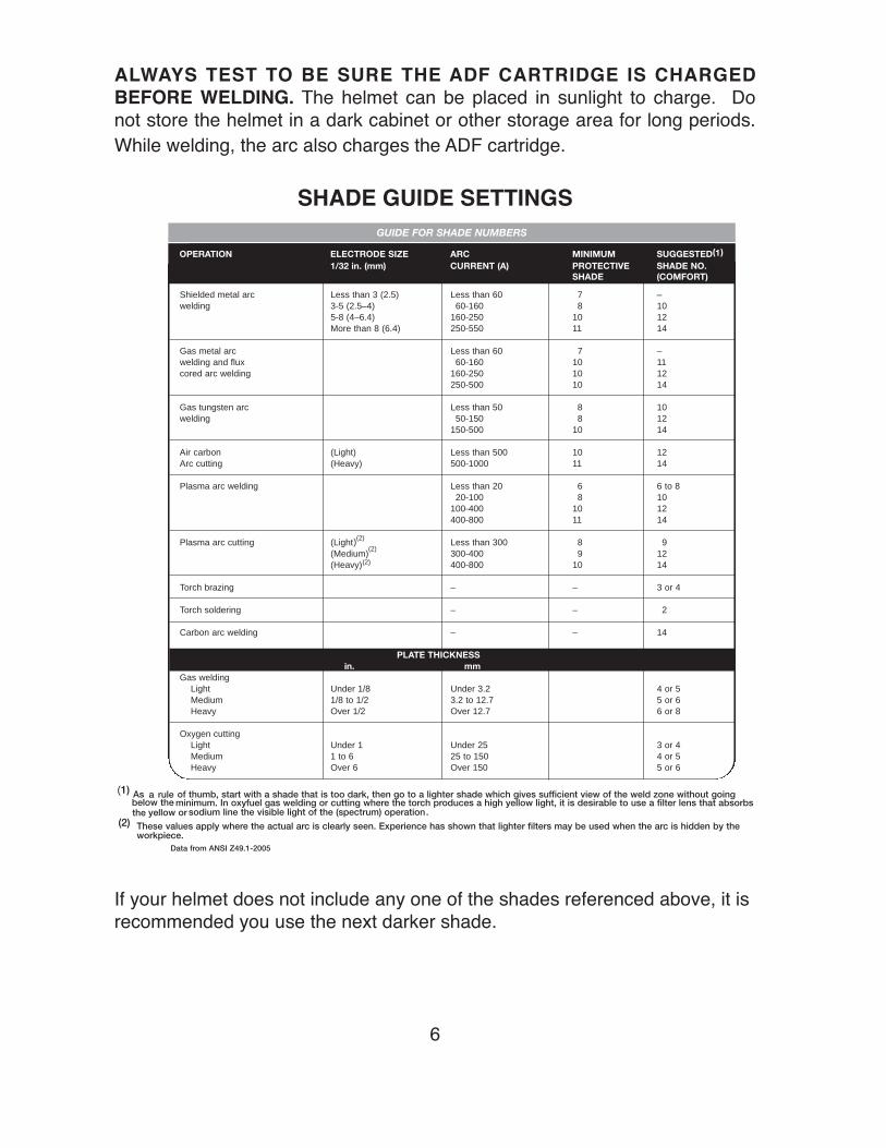
ALWAYS TEST TO BE SURE THE ADF CARTRIDGE IS CHARGEDBEFORE WELDING. The helmet can be placed in sunlight to charge. Donot store the helmet in a dark cabinet or other storage area for long periods.While welding, the arc also charges the ADF cartridge.
SHADE GUIDE SETTINGS
If your helmet does not include any one of the shades referenced above, it isrecommended you use the next darker shade.
6
GUIDE FOR SHADE NUMBERS
OPERATION ELECTRODE SIZE ARC MINIMUM SUGGESTED(1)
1/32 in. (mm) CURRENT (A) PROTECTIVE SHADE NO.SHADE (COMFORT)
Shielded metal arc Less than 3 (2.5) Less than 60 7 –welding 3-5 (2.5–4) 60-160 8 10
5-8 (4–6.4) 160-250 10 12More than 8 (6.4) 250-550 11 14
Gas metal arc Less than 60 7 –welding and flux 60-160 10 11cored arc welding 160-250 10 12
250-500 10 14
Gas tungsten arc Less than 50 8 10welding 50-150 8 12
150-500 10 14
Air carbon (Light) Less than 500 10 12Arc cutting (Heavy) 500-1000 11 14
Plasma arc welding Less than 20 6 6 to 820-100 8 10
100-400 10 12400-800 11 14
Plasma arc cutting (Light)(2)
(2)
(2) Less than 300 8 9(Medium) 300-400 9 12(Heavy) 400-800 10 14
Torch brazing – – 3 or 4
Torch soldering – – 2
Carbon arc welding – – 14
PLATE THICKNESSin. mm
Gas weldingLight Under 1/8 Under 3.2 4 or 5Medium 1/8 to 1/2 3.2 to 12.7 5 or 6Heavy Over 1/2 Over 12.7 6 or 8
Oxygen cuttingLight Under 1 Under 25 3 or 4Medium 1 to 6 25 to 150 4 or 5Heavy Over 6 Over 150 5 or 6
(1) As a rule of thumb, start with a shade that is too dark, then go to a lighter shade which gives sufficient view of the weld zone without goingbelow theminimum. In oxyfuel gas welding or cutting where the torch produces a high yellow light, it is desirable to use a filter lens that absorbsthe yellow or sodium line the visible light of the (spectrum) operation
(2) These values apply where the actual arc is clearly seen. Experience has shown that lighter filters may be used when the arc is hidden by theworkpiece.
.
Data from ANSI Z49.1-2005
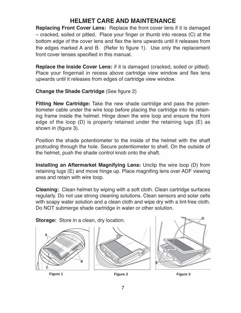
HELMET CARE AND MAINTENANCEReplacing Front Cover Lens: Replace the front cover lens if it is damaged– cracked, soiled or pitted. Place your finger or thumb into recess (C) at thebottom edge of the cover lens and flex the lens upwards until it releases fromthe edges marked A and B. (Refer to figure 1). Use only the replacementfront cover lenses specified in this manual.
Replace the Inside Cover Lens: if it is damaged (cracked, soiled or pitted).Place your fingernail in recess above cartridge view window and flex lensupwards until it releases from edges of cartridge view window.
Change the Shade Cartridge (See figure 2)
Fitting New Cartridge: Take the new shade cartridge and pass the poten-tiometer cable under the wire loop before placing the cartridge into its retain-ing frame inside the helmet. Hinge down the wire loop and ensure the frontedge of the loop (D) is properly retained under the retaining lugs (E) asshown in (figure 3).
Position the shade potentiometer to the inside of the helmet with the shaftprotruding through the hole. Secure potentiometer to shell. On the outside ofthe helmet, push the shade control knob onto the shaft.
Installing an Aftermarket Magnifying Lens: Unclip the wire loop (D) fromretaining lugs (E) and move hinge up. Place magnifing lens over ADF viewingarea and retain with wire loop.
Cleaning: Clean helmet by wiping with a soft cloth. Clean cartridge surfacesregularly. Do not use strong cleaning solutions. Clean sensors and solar cellswith soapy water solution and a clean cloth and wipe dry with a lint-free cloth.Do NOT submerge shade cartridge in water or other solution.
Storage: Store in a clean, dry location.
7
Figure 1 Figure 2 Figure 3
Figure 1 Figure 2 Figure 3
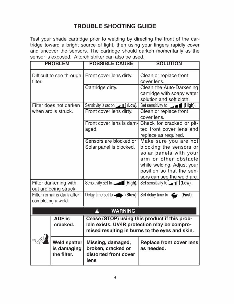
SOLUTION
Clean or replace frontcover lens.Clean the Auto-Darkeningcartridge with soapy watersolution and soft cloth.Set sensitivity to (High).Clean or replace frontcover lens.Check for cracked or pit-ted front cover lens andreplace as required.Make sure you are notblocking the sensors orsolar panels with yourarm or other obstaclewhile welding. Adjust yourposition so that the sen-sors can see the weld arc.Set sensitivity to (Low).
Set delay time to (Fast).
Replace front cover lensas needed.
POSSIBLE CAUSE
Front cover lens dirty.
Cartridge dirty.
Sensitivity is set on (Low).Front cover lens dirty.
Front cover lens is dam-aged.
Sensors are blocked orSolar panel is blocked.
Sensitivity set to (High).
Delay time set to (Slow).
Missing, damaged,broken, cracked ordistorted front coverlens
TROUBLE SHOOTING GUIDE
Test your shade cartridge prior to welding by directing the front of the car-tridge toward a bright source of light, then using your fingers rapidly coverand uncover the sensors. The cartridge should darken momentarily as thesensor is exposed. A torch striker can also be used.
8
PROBLEM
Difficult to see throughfilter.
Filter does not darkenwhen arc is struck.
Filter darkening with-out arc being struck.Filter remains dark aftercompleting a weld.
ADF iscracked.
Weld spatteris damagingthe filter.
WARNING
Cease (STOP) using this product if this prob-lem exists. UV/IR protection may be compro-mised resulting in burns to the eyes and skin.
WARRANTY INFORMATION
WARRANTY INFORMATION: These helmets are warranted for a period oftwo years. Please contact us at 1 (800) 833-9353 for any service or warrantyquestions.
SPATTER DAMAGE IS NOT COVERED BY WARRANTY:Do not use this product without the correct protective clear cover lensesinstalled properly on both sides of the Auto-Darkening Filter cartridge (ADF).The cover lenses supplied with this helmet are properly sized to work withthis product and substitutions from other suppliers should be avoided.
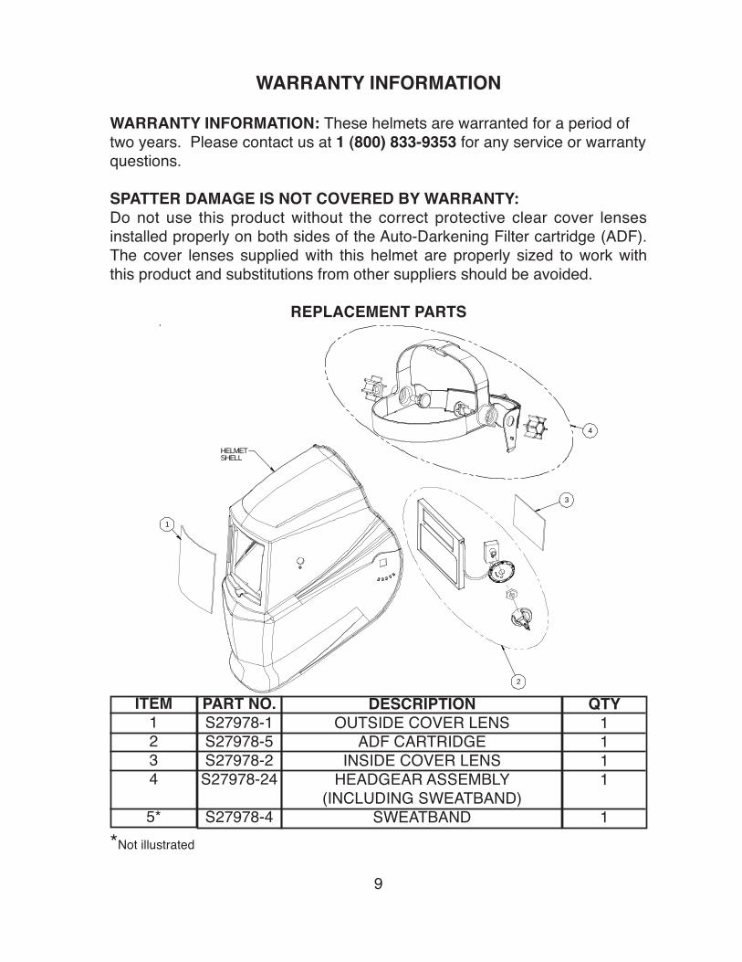
REPLACEMENT PARTS
*Not illustrated
9
1
2
3
4HELMETSHELL
1
2
3
4
HELMETSHELL
ITEM1234
5*
QTY1111
1
PART NO.S27978-1S27978-5S27978-2
S27978-24
S27978-4
DESCRIPTIONOUTSIDE COVER LENS
ADF CARTRIDGEINSIDE COVER LENS
HEADGEAR ASSEMBLY (INCLUDING SWEATBAND)
SWEATBAND

• Sales and Service through Subsidiaries and Distributors Worldwide •Cleveland, Ohio 44117-1199 U.S.A. TEL: 216.481.8100 FAX: 216.486.1751 WEB SITE: www.lincolnelectric.com
• World's Leader in Welding and Cutting Products •