AUG 2 4 2018...Cokenergy's waste heat recovery steam generators (HRSGs), arranged four per oven...
39
UNITED STATES ENVIRONMENTAL PROTECTION AGENCY REGION 5 77 WEST JACKSON BOULEVARD CHICAGO, IL 60604-3590 AUG 2 4 2018 CERTIFIED MAIL RETURN RECEIPT REQUESTED Luke Ford Co1vorate El- l&S Manager Cokenergy LLC 3210 Waitling Street - Mail Code 2-991 East Chicago, IN 46312 REPLY TO THE ATTENTION OF: RE: U.S. EPA's Conditional Approval ofCokenergy LLC's Preventive Maintenance and Operation Plan for the Indiana Harbor Facility Pursuant lo the Revised Consent Decree for the United States et al. v. Indiana Harbor Coke Company, el al. , 90-5-2-1-08555/) Dear Mr. ford : Thank you for your submi ssion , dated June 28 , 20 18 , of the Cokencrgy LLC ("Cokenergy") Preventive Ma intenance and Operation Plan ("PMO Plan") pursuant to Paragraph 23 of the above-captioned consent decree ("Decree"). Pursuant to Paragraph 58 of the Decree, and, after consultation with the State of lndiana, U.S. EPA approves the PMO Pl an, subject to Cokenergy adequately addressing the attached comments, questions, and proposed edits. After your review of the attached comments, it may be helpful to set up a call to provide further explanation of EPA 's concerns, and to facilitate the resolution of those concerns. To coordinate such a call, please direct your counsel to contact Cathy Banerjee Rojko or Nick McDaniel of the U.S. Department of Justice al 202-514-5315 or 202-514-0096, respectively. Sincerely, Sara J. Breneman Chief Air Enforcement and Compliance Assurance Branch Recycled/Recyclable • Pri nl ed with Vegelable Oil Based Inks on 100% Recycled Paper (100% Post Consumer)
Transcript of AUG 2 4 2018...Cokenergy's waste heat recovery steam generators (HRSGs), arranged four per oven...
UNITED STATES ENVIRONMENTAL PROTECTION AGENCY REGION 5
77 WEST JACKSON BOULEVARD CHICAGO, IL 60604-3590
AUG 2 4 2018
CERTIFIED MAIL RETURN RECEIPT REQUESTED
Luke Ford Co1vorate El-l&S Manager Cokenergy LLC 3210 Waitling Street - Mail Code 2-991 East Chicago, IN 46312
REPLY TO THE ATTENTION OF:
RE: U.S. EPA's Conditional Approval ofCokenergy LLC' s Preventive Maintenance and Operation Plan for the Indiana Harbor Facility Pursuant lo the Revised Consent Decree for the United States et al. v. Indiana Harbor Coke Company, el al. , 90-5-2-1-08555/)
Dear Mr. ford:
Thank you for your submission, dated June 28, 2018, of the Cokencrgy LLC ("Cokenergy") Preventive Maintenance and Operation Plan ("PMO Plan") pursuant to Paragraph 23 of the above-captioned consent decree ("Decree"). Pursuant to Paragraph 58 of the Decree, and, after consultation with the State of lndiana, U.S. EPA approves the PMO Plan, subject to Cokenergy adequately addressing the attached comments, questions, and proposed edits.
After your review of the attached comments, it may be helpful to set up a call to provide further explanation of EPA 's concerns, and to facilitate the resolution of those concerns. To coordinate such a call, please direct your counsel to contact Cathy Banerjee Rojko or Nick McDaniel of the U.S. Department of Justice al 202-514-5315 or 202-514-0096, respectively.
Sincerely,
Sara J. Breneman Chief Air Enforcement and Compliance Assurance Branch
Recycled/Recyclable • Prinled with Vegelable Oil Based Inks on 100% Recycled Paper (100% Post Consumer)

cc: Chief, Environmental Enforcement Section Environment & Natural Resources Division U.S. Department of Justice P.O. Box 7611 Ben Franklin Station Washington, D.C. 20044-7611
Air Enforcement Division Director U.S. Environmental Protection Agency Office of Civil Enforcement Air Enforcement Division U.S. Environmental Protection Agency 1200 Pennsylvania Ave., NW Mail Code: 2242A Washington, DC 20460
Compliance Tracker Air Enforcement and Compliance Assurance Branch U.S. Environmental Protection Agency - Region 5 77 West Jackson BI vd. AE-18J Chicago, IL 60604-3590
Susan Tennenbaum U.S. Environmental Protection Agency-Region 5 77 West Jackson Blvd. C-14J Chicago, IL 60640-3590
Phil Perry Indiana Department of Environmental Management Chief, Air Compliance and Enforcement Branch 100 North Senate Avenue MC-61-53, IGCN 1003 Indianapolis, IN 46204-2251
Elizabeth A. Zlatos Indiana Department of Environmental Management Office of Legal Counsel 100 North Senate A venue MC-60-01 1GCN1307 Indianapolis, IN 46204-225 l
Thor Ketzback Brian Cave Leighton Paisner LLP 161 North Clark Street, Suite 4300 Chicago, IL 60601

··--- --1 Style Definition: Heading 1
[Company name]
[Document title]
[Document subtitle]
.---1 Deleted: ~ . . ·····---······ · ······ ··•·· ····-·-·-·-- -··-··-- ····-·-····-·· ~ '-'-------- - ~
June 2018
ot.l Cokenergy LLC
Table of Contents
Abbreviations
1.0 PMO Purpose/Overview
2.0 Plant Description
3.0 Plant Maintenance Philosophy
4.0 Heat Recovery Steam Generators (HRSGs)
5.0 Flue Gas Desulfurization System
6.0 Continuous Emissions Monitoring System
7.0 Emissions Minimization Efforts with II-ICC
8.0 Events Outside ofCokenergy Control
9.0 PMO Plan Management and Revisions
Z. ......................................................... •···{'.:D=e=le=t=ed=:=22=2= ============'. J, .............. ..... ................................... •···{~D:::::e::le=te:::::d=: 3=3=3 = = =========='. J. ....................................................... •·····{'.:o=e=le=te=d=: 3=3=3============: ~ ......................................................... •···{'.:D=e=le:::::t::ed=:=s6=5= ==========:::::'. .!i. ........................................................ •···· {'.:D=e=le=te=d=: 6=6=6===========~ li ....................................................... •···{'.:D=e=le=t=ed=:=16=2=0=19======= = =====: Mi.. ...................................................... •····{'.:D=e=le=te=d=: 2=6=33=3=1 = =========~ ~ ....................................................... •···{'.:D=e=le=t=ed=:=29=3=63=4= ======== ==='. ~ ....................................................... •···{:::D=e=le=t=ed=:=2=93=63=4= ==========::::::: 19.. ........................................................ •··{'-D_e_le_t_ed_:_3_03_73_5 ___________ ~
Attachment I - HRSG Cleaning Procedure
Attachment 2 - Example HRSG Maintenance Outage Work Orders
Attachment 3 - CEMS Shelter Layout
Preventative Maintenance and Operation Plan Page I
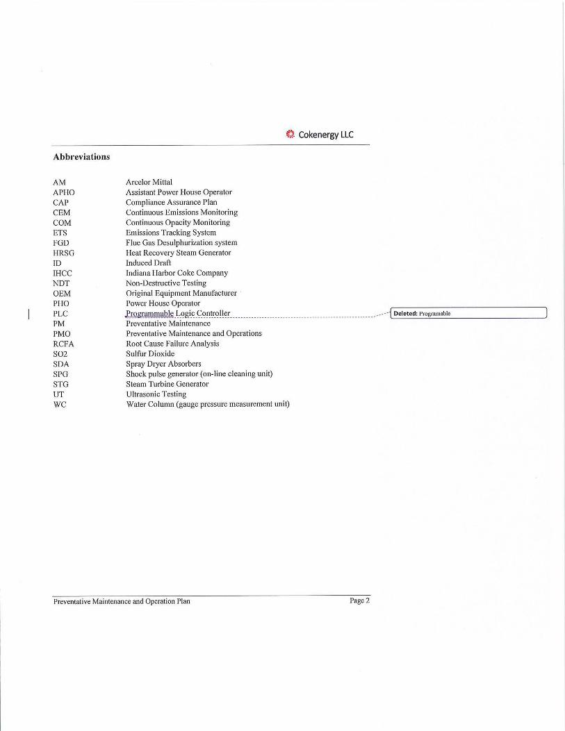
Abbreviations
AM APHO CAP CEM COM ETS FGD HRSG ID IHCC NDT OEM PHO PLC PM PMO RCFA S0 2 SDA SPG STG UT WC
ArcelorMittal Assistant Power House Operator Compliance Assurance Plan Continuous Emissions Monitoring Continuous Opacity Monitoring Emissions Tracking System Flue Gas Desulphurization system Heat Recovery Steam Generator Induced Draft Indiana Harbor Coke Company Non-Destructive Testing Original Equipment Manufacturer Power House Operator
~). Cokenergy LLC
g rogrammable -~-<?gi_~_<;:_<?~~1'.<?!!~~-______ ______________________________ _________________ _ .. --· i'--o_e_le_t_ed_:_P_ro..::.gr_ru_n_ab_le _ _____ ____ __,
Preventative Maintenance Preventative Maintenance and Operations Root Cause Failure Analysis Sulfur Dioxide Spray Dryer Absorbers Shock pulse generator ( on-line cleaning unit) Steam Turbine Generator Ultrasonic Testing Water Column (gauge pressure measurement unit)
Preventative Maintenance and Operation Plan Page 2

~'- Cokenergy LLC
1.0 PMO Purpose/Overview This document outlines the Preventative Maintenance and Operations Plan (PMO Plan) for the Cokenergy facility which is located adjacent to the Indiana Harbor Coke Company. This plan has been prepared in compliance with Title V Operating Permit No. 089-36965-00383 (Air Permit). This PMO Plan has been developed pursuant to a Consent Decree with the United States, the State of Indiana, Indiana Harbor Coke Company and SunCoke Energy which was lodged by the United States District Court for the Northern District oflndiana with an Effective Date of XX, 20 18
(Consent Decree).
As required by the Consent Decree, the PMO Plan details the facility's approach for exercising good operating, engineering, and air pollution control practices and for minimiz ing emissions,and _ . .. --- j'-o_e_le_t_ed_:_. _____________ _,
ensuring compliance with the Consent Decree. More specifically, the PMO Plan provides for the steps that Cokenergy will take to allow for the continuous operation (to the fullest extent practical)
of the heat recovery steam generators and flue gas ,P.~_~t_tlf~1_rization __ S).'~~e_f!!. ~~~Y~-~i:i .. P}~i:111_~~-----· -- i'-o_e_le_t_ed_:_de_s_ul'-pl_m_riz_a_tio_n _________ ...,
maintenance periods and during outages with minimization of emissions. All employees and contractors ofCokenergy are required to follow theJlrovisions detailed_in this PMO _plan. _____ _______ .----{ Deleted: guidelines '-----"----------- ---' 2.0 Plant Description The Cokenergy facility is located in ArcelorMittal (AM) Steel's Indiana Harbor Works in East Chicago, Indiana. The Cokenergy facility is a first-of-a-kind combined heat and power system that uses the waste heat in the flue gas from the metallurgical coke facility to produce steam and power for the AM Indiana Harbor steel mill. AM's Indiana Harbor Works is a large-scale, integrated steel mill. Within the Indiana Harbor Works, SunCoke Energy owns and operates the Indiana Harbor Coke Company (IHCC) metallurgical coke plant, consisting of four batteries of67 coke ovens each to produce coke for AM's blast furnaces. The coke ovens are non-recovery type, which, combusts the coke_ oven_gas_ in the ovens as_it _is_generated. _The coke ovens exhaust _the -------{~o_e_le_te_d_:_fi_uI-=-Iy _________ ___ ...,
combusted hot flue gas, which must be cooled and environmentally treated, into a series of
refractory-lined manifolds to collect the gas.
Cokenergy's waste heat recovery steam generators (HRSGs), arranged four per oven battery, receive and recover heat from the coke oven exhaust gas, producing power-grade steam and cooling the gas in the process. The superheated steam is used to generate electricity in a GE industrial condensing/extraction steam turbine. With the steam and power generated in this process, Cokenergy supplies electricity as well as 300 psig process steam to the AM Indiana Harbor Works. Cokenergy's Flue Gas.Qesulfurization (FGD)_system then _also environmentally _.---- j'-o_e_le_t_ed_:_D_es_u-'-Ip_In_iri_za_ti_o,_, ___ _____ __,
treats the cooled flue gas, after it passes through the HRSGs, to remove sulfur dioxide (SO2) and particulate. Flue gas temperatures and flows, and corresponding steam flows, change depending on where a g iven coke battery is in its coking cycle.
The Cokenergy facility consists of:
• Sixteen (I 6) heat recovery steam generators (HRS Gs), 4 per coke oven battery, which recover heat from the flue gas, and cool it for environmental treatment;
• Flue gas ductwork to manifold the flue gas from the HRSGs to the FGD system;
Preventative Maintenance and Operation Plan Page3
t:t Cokenergy LLC
• Two (2) spray dryer absorber (SDA) vessels to allow mixing of the flue gas with sorbent to remove S02 from the flue gas;
• A thirty-two (32) compartment pulse jet, fabric filter baghouse to remove pa1ticulate from the flue gas;
• Two induced draft (ID) fans that are responsible for pulling draft through the entire flue gas system from the ovens to the ID fans;
• One GE extraction/condensing steam turbine generator (STG), rated at 95MW, that accepts the generated steam from the HRSGs, and ancillary equipment for operation of the STG, including a 6-cell cooling tower, boiler feedwater heater, and two deaerators.
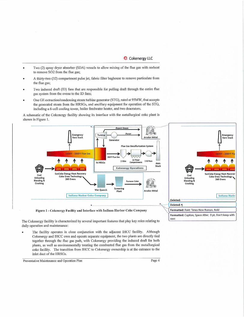
A schematic of the Cokenergy facility showing its interface with the metallurgical coke plant is shown in Figure I.
A w---+
fl::,...:::: * I _ _ _
, __ --;-}~------- r,p.;rn•::~~~------~-- ---a;-----····· El !• ~ ....._A_rc_el_or_M_1_tt_a~l-
--.....;,►oflue :D□esulfurlza:o~ l50'f ftue CiH
2 SOAs C~~::!:nu 2 ID P'ans 16 HRSGs Main Stack
Cokener9y Opero.tlons
Coal SunCoke Enerey Heat Recovery
Unloadlni Coke Oven Technotoay ~ Blendina & 268 Ovens
Crushlne Furnacr Cob
Wet Quench
l ndi:ina Harbor Coke Compo.ny
Screening Plant ArcelorMittal
Deleted:
A w---+ Coal
Unloadlna Blendine II Cru,hlne
n Emeraency Li Vent Stack
i--i
SunCoke Enu9y He.1t Recover Coke Oven T echnoloay '-
268 Ovens ~
Jndkma Harbc
L. -·- -- - - - - -- - - -·. - -- - - - - - - - - - - - - - - - - - -- - - - - - - - - - - - - - - - - -- .. <:,.- ---- Deleted: 1)
Figure J - Cokenergy Facility and Interface with Indiana Harbor Coke Company \:,:)=Fo=r=m=a=t=te.;;d_: -Fo_n_t-:T-im- es- N- ew- R=o=m-a-n,-B-o-ld----~
The Cokenergy facility is characterized by several important features that play key roles relating to daily operation and maintenance:
• The facility operates in close conjunction with the adjacent IHCC facility. Although Cokenergy and IHCC own and operate separate equipment, the two plants are directly tied together through the flue gas path, with Cokenergy providing the induced draft for both plants, as well as environmentally treating the combusted flue gas from the metallurgical coke facility. The transition from !HCC to Cokenergy ownership is at the entrance to the inlet duct of the HRS Gs.
Preventative Maintenance and Operation Plan Page 4
Formatted: Caption, Space After: 0 pt, Don't keep with next
t} Cokenergy LLC
• Induced draft from Cokenergy's ID fans allows the entire facility to operate at negative pressure (be low atmospheric pressure) providing the motive force to pull flue gas from the ovens through the HRSGs and connecting flue gas ductwork to the FGD unit. A key operational requirement is to sustain target draft at the interface between the FGD and the oven batteries to maintain the required operational draft at the ovens.
• Because IHCC's metallurgical coke ovens continuously operate, generating flue gas 24 hours a day, 7 days a week, 365 days per year, the Cokenergy facility also has a requirement to continuously operate.
• The FGD system has a 100% availability requirement per the Air Permit. This means that the FGD facility cannot be taken offline as a whole for maintenance. Due to the original design of the plant, this means that some areas of the FGD system are not accessible for
routine maintenance.
• Because of the close dependence between the two plants, there is a need for daily communication between the two plants at multiple levels so that maintenance activities can be coordinated, and forced outage events can be more efficiently and quickly resolved.
• Both the Cokenergy and the IHCC facility are contractors to the AM Indiana Harbor integrated steelmaking facil ity as host. Both Cokenergy and !HCC ultimately provide services to AM - Cokenergy in the form of electrical power and process steam. Due to the electrical configuration of Cokenergy within the larger AM facility, Cokenergy is also dependent on electrical stability of portions of the internal AM electrical grid.
3.0 Plant Maintenance Philosophy The preventative maintenance approach referenced herein is critical to achieve the necessary level of reliability across the environmental and environmentally-related systems. A proactive approach and the execution of appropriate preventative maintenance is a cornerstone ofCokenergy's PMO.
The following concepts are implemented throughout Cokenergy's maintenance plan: • Incorporate a thorough preventative maintenance plan across all plant systems, with
regularly established inspection and maintenance intervals. • Define maintenance intervals and maintenance processes based on Original Equipment
Manufacturer (OEM) recommendations, but revise and enhance the preventative maintenance work as necessary based on practical plant experience.
• Use of an industry accepted, web-based Work Order tracking system (Maximo) to identify, schedule, and track all facility planned and break-in work.
• Maintain and regularly review inventory of critical spare parts.
• Involvement and communication of maintenance actions with all Cokenergy management,
staff, operators, and contractors.
Preventative Maintenance and Operation Plan Page 5

t} Cokenergy LLC
4.0 Heat Recovery Steam Generators (HRSGs) The sixteen waste-heat recovery steam generators (HRSGs) at Cokenergy are designed to produce steam from the heat recovered from flue gas generated in a set of co-located metallurgical coking batteries. The HRSGs generate power-grade steam that is sent to an on-site steam turbine generator which produces power for end-customer AM. Each of the HRSGs was originally manufactured by Nooter/Erikson in 1997/ 1998 and contain both bare and finned tube heat transfer sections. Each HRSG contains a waterwall, evaporator, superheater and a separate finned economizer sections as shown in Figure 2. Evaporator and evaporative water wall tubes are rolled into the main upper steam drum and two lower "mud" drums. The HRS Gs are unfired, natural-circulation style HRS Gs and all steam generation is developed from the waste heat in the fu lly combusted coke oven flue gas which is drawn through the HRSGs by the draft from the downstream ID fans. The design conditions for the HRSGs are 865 psig pressure, providing superheated steam at 725°F.
Side View
Plan View
Evaporator Sections #1 & #2 Tubes (bare tube)
Superheater Module
(bare tube)
Evaporator Sections #3A/3B
(finned tube)
,.Figurc_2_- HRSG Layout and Tube Surface __________________________________ < :··· >-o_el_e_te_d_: .;.'I ______ ___ ____ -<
All sixteen of the HRS Gs were retubed between 2010 and 2015, to replace the carbon steel tube materials which were thinned by repeated water washing. Off-line water washing is used to remove gas-side fouling deposits caused by the coke oven gas. Here " retube" means that all carbon steel bare, finned, and waterwall tubes were removed and replaced section by section, resulting in substantially new HRSG heat transfer circuits. The exception for replaced heating surface was the alloy superheater sections, as well as the thick-wall steam drums. Neither of these groups were shown to have experienced any noticeable material thinning.
As part of the retubing process, the specified tube thicknesses were increased, and most finned tubes sections had their fin-to-fin spacing increased to reduce the impact of fouling and improve
Preventative Maintenance and Operation Plan Page 6
Formatted: Font: 11 pt, Bold

t:t Cokenergy LLC
both on-line and off-line cleaning. The replacement evaporator tubes, both smooth and finned, have been changed in material specification from SA 178D to SA2 l 0C. The waterwall has been changed from SA 178A to SA I 92. Cokenergy decided, following consultation with Nooter/Eriksen, to increase the minimum wall thickness for the evaporator tubes from 0.105" to 0.135" for re-tubing. The outer tube diameters have not been changed.
HRSG On-Linc Cleaning System Each HRSG includes an automated on-line cleaning system which operates throughout each day of operation when the HRSG is on-line. The original clean ing system is a steam sootblower system from Clyde Bergemann Power Group. The sootblower configuration incorporates six retractable sootblowers in the horizontal section, two retractable sootblowers between the upper and lower the economizer modules, and four fixed rotating sootblowers, with two above and two below the economizer modules.
Starting in 201 7, Cokenergy began replacing the aging sootblower equipment with a pulsed pressure technology called Shock Pulse Generators (SPGs) offered in partnership between the OEM Explosion Power and Clyde Bergemann. The fourteen original sootblowers are removed and replaced by two SPGs which generate a gas-side pressure pulse every one-to-two hours in the HRSG flue gas stream which knocks the deposits from the heat transfer surface throughout the HRSG. This system has been proven with more than 18 months testing and evaluation to be more effective than the original steam sootblowing system. It has an additional benefit that it does not introduce additional moisture into the HRSG flue gas which can result in gas-side corrosion.
4.1 INSPECI'ION R EQUIREMENTS
All HRSGs are scheduled for an annual inspection each year, completed by a third-party team specializing in boiler equipment inspections.
The inspection team photographs internal condition and key external items requiring maintenance. Internal photos provide a basis for year-to-year comparison of equipment conditions. A comprehensive inspection report is completed by the inspection team for each HRSG. Cokenergy maintains these records onsite.
As part of the inspection process, tube wall thickness measurements are taken using ultrasonic thickness (UT) measurements, or equivalent techniques, at consistent points throughout each 1-IRSG for evaporator, superheater, waterwall sections, and economizer bends to permit routine monitoring of tube condition and wall thickness year-to-year. This process and data will be described further in Section 4.4.
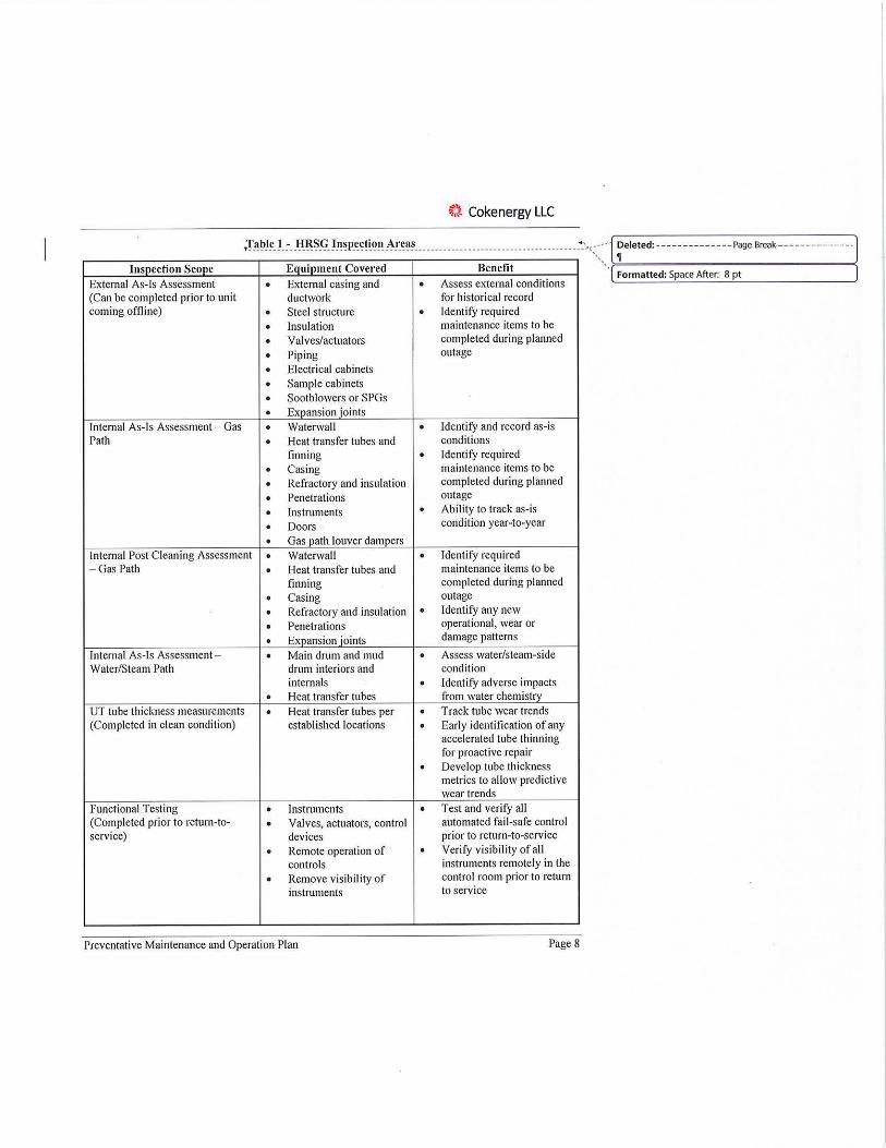
1-IRSG inspection scope is listed in Table 1.
Preventative Maintenance and Operation Plan Page 7
~} Cokenergy LLC
lnsocction Scone Equipment Covered Benefit
External As-Is Assessment . External casing and • Assess external conditions
,Table 1 - HRSG Inspection Areas --- ------------------------··----·--·· +-,-:,::~. ~eleted: ------ - ---- - --Page Break---- - ---------·
Formatted: Space After: 8 pt
(Can be completed prior to unit ductwork for historical record coming offline) . Steel structure • Identify required
• Insulation maintenance items to be
• Valves/actuators completed during planned . Piping outage
• Electrical cabinets • Sample cabinets . Sootblowers or SPGs
• Expansion joints Internal As-Is Assessment - Gas . Waterwall • Identify and record as-is Path • Heat transfer tubes and conditions
finning • Identify required . Casing maintenance items to be
• Refractory and insulation completed during planned . Penetrations outage
• Instruments . Ability to track as-is . Doors condition year-to-year
• Gas path louver dampers Internal Post Cleaning Assessment . Waterwall • Identify required - Gas Path • Heat transfer tubes and maintenance items to be
finning completed during planned . Casing outage
• Refractory and insulation • Identify any new
• Penetrations operational, wear or
• Exnansion ioints damage patterns
Internal As-Is Assessment - . Main drum and mud • Assess water/steam-side Water/Steam Path drum interiors and condition
internals • Identify adverse impacts • Heat transfer tubes from water chemistrv
UT tube thickness measurements • Heat transfer tubes per . Track tube wear trends (Completed in clean condition) established locations • Early identification of any
accelerated tube thinning for proactive repair . Develop tube thickness metrics to allow predictive wear trends
Functional Testing • Instruments . Test and verify all (Completed prior to return-to- • Valves, actuators, control automated fail-safe control service) devices prior to return-to-service
• Remote operation of . Verify visibility of all controls instruments remotely in the
• Remove visibility of control room prior to return instruments to service
Preventative Maintenance and Operation Plan Page 8
4.2 MAINTENANCE REQUIREMENTS
Gas-side Cleaning Process
~). Cokenergy LLC
Since the retubing of the HRSGs from 2010 through 2015, Cokenergy uses an established buffered water wash process when cleaning the HRSGs. The waterwash is required to effectively clean the HRSGs due to their original design, which include large portions of the heat transfer surface with finned tubes. This design was incorporated in the original concept for the first-of-a-kind application at the coke plant with heat recovery to maintain a small footprint for the HRSGs. However, in practice, the fouling particulate materials generated in the coking process produce deposits high in sulfur, chlorides, and alkali metals which tend to stick to the tube surfaces, and cannot be effectively removed from the finned tube surfaces except by high pressure water
washing.
Because the water wash process mixes water with the highly acidic deposit materials, Cokenergy has developed a buffered wash process which mixes water with soda ash to effectively neutralize the combined waste water. The pH levels of both the wash water and the combined waste water are periodically tested to ensure that the generated waste water remains in an acceptable neutral range (pH 6-9) to minimize offline corrosion of the carbon tubes.
The cleaning contractor follows the HRSG cleaning procedure which includes monitoring of the wash and waste water. Cokenergy staff inspect all HRSGs when cleaning is completed by the cleaning contractor to confirm satisfactory condition. If the HRSG Area Manager, or designee, determines the cleaning level is not satisfactory, the cleaning contractor will complete additional washes of the required areas until inspection is acceptable. All tube surfaces are washed with midto-high pressure buffered water solution, followed by a final pure water rinse. A ll tube modules are included in the wash process.
Waste water is collected within the HRSG during the cleaning process, and then processed in Cokenergy's wash water handling area, where particulate is separated from liquid content. Liquid content is then reused as possible for subsequent washes, as long as neutral pH levels can be
obtained.
Water washes.will be performed at least once a year, as _part of each. HRS Gs annual maintenance __ .. -· ·{ Deleted: are typically carried 0111
outage, where the unit is inspected prior to the cleaning, and then post-cleaning, to best understand year-to-year fouling characteristics and performance of on-line cleaning systems. However, if necessary, a HRSG can be taken offline for a supplementary water wash cleaning if online instrument data indicate that the HRSG has become fouled prior to its scheduled cleaning. This may occur due to changes in coke oven coal mixtures, charge weights, or flue gas flow rates from the ovens which tend to carry more particulate from the coking process.
The Cokenergy standard HRSG Cleaning Procedure is included as Attachment I .
,Routine Preventative .Maintenance Scope .... ................. . . ................. .. _ .......... . ... . ....... ... :-:,::~, ~eleted: -- -- - ---------Page Break---- ----------·
In addition to the annual inspection and cleaning, a set of additional routine preventative >=---------- - ---------< Formatted: Left, Space After: 8 pt maintenance tasks are assigned and completed for each HRSG at regular intervals. Many of these tasks which require internal access to the internal gas path or the internal steam/water side are
Preventative Maintenance and Operation Plan Page 9

t) Cokenergy LLC
scheduled during planned annual outages. There is a lso a routine set of preventative maintenance tasks that are completed weekly or monthly while the HRSG is online.
Annual Maintenance Outage Scope The tasks included in the annual maintenance outage period are primarily those which require the HRSG to be offline for a planned period, usually for internal access, or for access to steam or water
valves which cannot be maintained while the HRSG is on-line. These maintenance tasks are scheduled to include tasks for the HRSG cleaning and the internal as-is and post-cleaning inspections, to minimize time that the HRSG is off-line and so to minimize venting. All maintenance items as listed here are completed to ensure that each HRSG operates safely and reliably and at best efficiency within its design performance range. During each a1111ual outage, each HRSG typically also receives its annual state inspection.
Annual maintenance tasks include:
• Inspection and maintenance all steam- and water-side valves and actuators, including packing
as required; • Economizer and general tube inspections, including tube thickness? • Inspection and maintenance for all gas-side louver damper and isolation damper equipment,
including seals and actuators; • Inspection, calibration, and testing for all instruments, w ith focus on critical and/or controlling
instruments such as drum level transmitters, Eye Hye independent level monitoring, inlet gas temperature thermocouples, and pressure transmitters;
• Inspection and wear-part maintenance for each unit's on-line cleaning system SPG (or sootblowers for units where they are still in use).
• Discuss triggers for repair. timelines?
• ETS correlations and testing?
An example list (for HRSG D4) of standard annual maintenance work orders as scheduled in
Maximo are included as Attachment 2 for reference.
It should be noted that whenever possible, unplanned work order maintenance tasks are held and completed during the planned annual outages to minimize venting time for each HRSG. The exception to this is any break-in maintenance which is required to ensure active control and reliable operation and ca1111ot wait until the annual planned outage.
Routine Maintenance Scope Conducted Betw een Annual Outages In addition to the annual outage maintenance items, there are routine preventative maintenance
tasks conducted more frequently. These r~~t_i!1.~ . .P~~-\/~_f!!11!!Y~ . !"!1.1!!f_l!~_f!l:\_l!~~-l:l.~~i_\/!!i_~~-•wil l be ___ ____ Deleted: are
scheduleC\ __ b1:1~e~ __ ~~l?-~l_l_ recommendat i~ns _ -~)'- .!~~-. 9.~M, __ 11!]_~(9_r __ ~l:l~.1'.~-_ ~_p~11 __ p_ra~_tj~_1!!. J?l11!1_! .:- ·-. · >-D_ e_l-et_e_d-,,-vh_ic_h_ar_e_ty_p_ic-al-Iy- ---------(
experience, as set forth below. · Deleted: on weekly and monthly basis, as recommended
Routine, periodic preventative maintenance tasks that will be completed when each HRSG is on-
line include:
Preventative Maintenance and Operation Plan Page 10
ti Cokenergy LLC
• Continuous drum blowdown, which is maintained at limited continuous daily levels to ensure good water chemistry;
• Monthly intermittent blowdowns from each mud drum, to maintain good water chemistry and eliminate possible buildup of residual in the lower (mud) drums;
• Weekly water/steam samples collected from each HRSGs sample cabinet, to allow for
routine testing of water chemistry conditions; • Completion of daily rounds by Cokenergy APHO, to identify incipient steam or water leaks
at valves, as well as routine inspection of external operating equipment such as the on-line
cleaning SPG units.
4.3 ,HRSG _HEALTH DATA ______ ______ . __ ___ ______ _______ . _______________ ______________ _______________ __ _____ ____ .· · ·{L_D_e_le_te_d__.:: 1,..___ _ ______ ___ __.J
As noted in Section 4.2, heat transfer tube thickness data for each HRSG is collected during each annual inspection outage. This tube thickness data, captured at a consistent set of locations for each tube module in each HRSG, form the basis for a set of HRSG health data that is collected,
maintained, and monitored year-to-year for each HRSG. This data is used in the manner described
below.
The tube thickness measurement data is collected using industry standard techniques for spot ultrasonic tube thickness (UT) measurements. These measurements are collected during each annual outage in a set of standardized locations in each of the HRSG tube module sections:
Evaporators # l, #2, 113A, #3B, upper and lower superheaters, membrane waterwall tubes, and upper and lower economizer tube bends. The data is collected after water wash cleaning is completed, and following sandblasting of the identified areas to ensure that good UT measurements can be obtained. The UT measurements are taken by the HRSG inspection team, which allows the measurements to be consistently collected by a limited number of technicians
familiar with the units.
The UT data for each module of each HRSG is then uploaded and maintained in a digital database
system which organizes and stores the data. The database system Cokenergy has selected is the Intertek boiler integrity management software package AW ARE. AW ARE is customized to collect and store the specific UT measurement data for HRSGs at the identified locations and organize it year-to-year for comparison and evaluation. Through A WARE's integrated analysis tools, the year-to-year wear rate for the tube thickness can be calculated, and thinn ing rates can be
forecast indicating when minimum tube thicknesses would be expected to be exceeded in specific areas. This capability allows Cokenergy management to then prepare for and take planned action to repair and/or replace tube wear prior to an unplanned and potentially significant failure event. As more tube thickness data is collected year-to-year, the accuracy of this forecasted thinning rate improves, so that planned preventative repairs or retubes can be scheduled prior to significant
failure events.
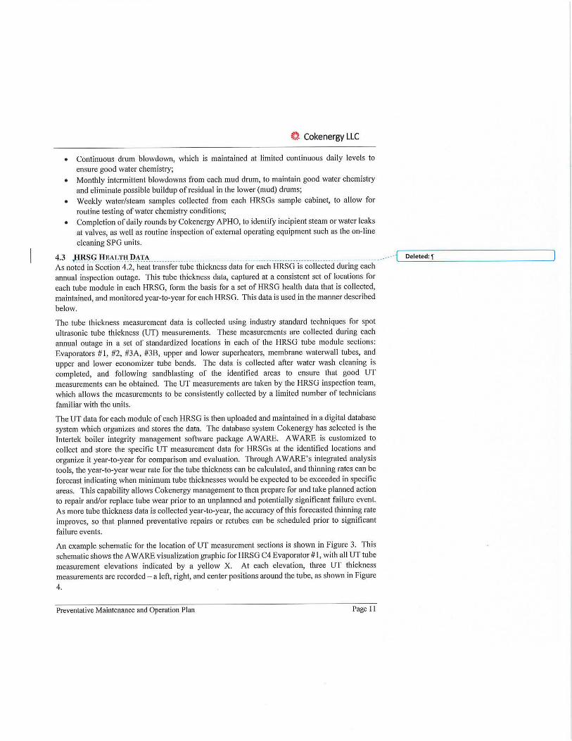
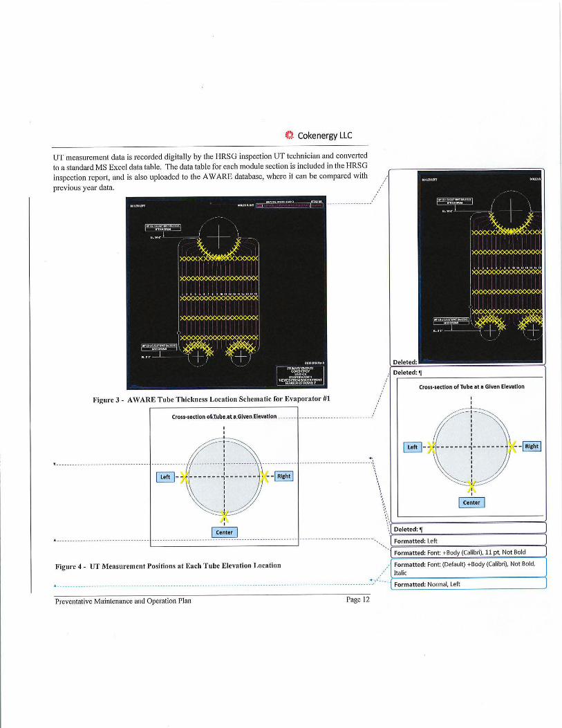
An example schematic for the location of UT measurement sections is shown in Figure 3. This
schematic shows the A WARE visualization graphic for HRSG C4 Evaporator# I , with all UT tube measurement e levations indicated by a yellow X. At each elevation, three UT thickness measurements are recorded - a left, right, and center positions around the tube, as shown in Figure
4.
Preventative Maintenance and Operation Plan Page 11
~). Cokenergy LLC
UT measurement data is recorded digitally by the HRSG inspection UT technician and converted to a standard MS Excel data table. The data table for each module section is included in the HRSG inspection report, and is also uploaded to the AW ARE database, where it can be compared with
previous year data.
-----------------
Figul'e 3 - A WARE Tube Thickness Location Schematic for Evapol'ator #1
Cross-section oUube.ata.GlvertElecv.aUon . ...... _____ ...... . ...•••..... ..•• /
I I . . ············ A ................................. ·,
~ -- !-------~------- • --IRlcht l \ '~ !J \.,, : \ I •' T •'
Deleted:
Deleted: ,i
Cross-section of Tube at a Given Elevation
•,'. ..... >-==~-=---==--=-< \ Deleted: ,i
.-: I Center I
" ------ -------- -- ------ -- ---------- - --- -- ----- ------------· ---- ----- -- --- -- ----- -· -- --- --· - --· ----· -- -- ----- --- -- ------ ~~ Formatted: Left ·-.. >===--=--= - ==--=--=<
Figure 4 - UT Measul'cmcnt Positions at Each Tube Elevation Location
-- ... . -- ----~_,;'-'----
Preventative Maintenance and Operation Plan Page 12
Formatted: Font: +Body (Calibri), 11 pt, Not Bold
Formatted: Font: (Default) +Body (Calibri), Not Bold,
Italic
Formatted: Normal, Left
~} Cokenergy LLC
4.4 CONTROL SYSTEM
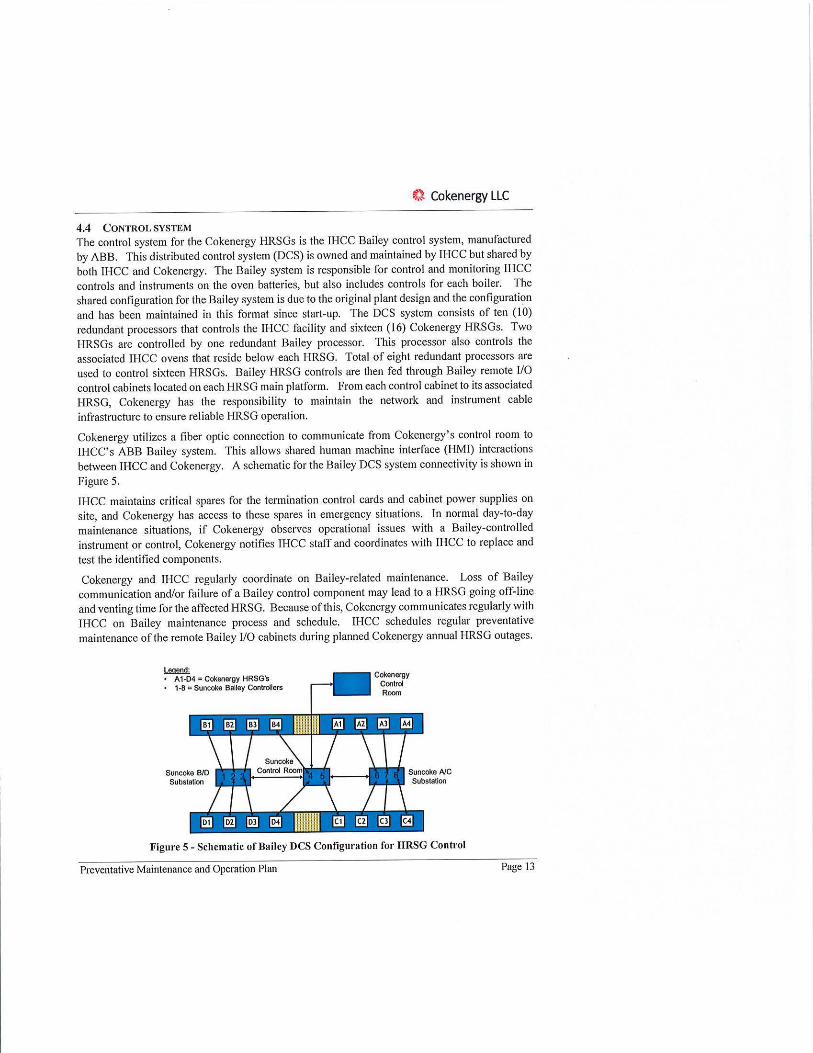
The control system for the Cokenergy HRSGs is the !HCC Bailey control system, manufactured by ABB. This distributed control system (DCS) is owned and maintained by !HCC but shared by both !HCC and Cokenergy. The Bailey system is responsible for control and monitoring !HCC controls and instruments on the oven batteries, but also includes controls for each boiler. The shared configuration for the Bailey system is due to the original plant design and the configuration and has been maintained in this format since start-up. The DCS system consists of ten ( IO) redundant processors that controls the IHCC facility and sixteen (16) Cokenergy HRSGs. Two HRSGs are controlled by one redundant Bailey processor. This processor also controls the associated !HCC ovens that reside below each HRSG. Total of eight redundant processors are used to control sixteen HRSGs. Bailey HRSG controls are then fed through Bailey remote 1/0 control cabinets located on each HRSG main platform. From each control cabinet to its associated I-IRSG, Cokenergy has the responsibility to maintain the network and instrument cable infrastructure to ensure reliable I-IRSG operation.
Cokenergy utilizes a fiber optic connection to communicate from Cokenergy' s control room to IHCC's ABB Bailey system. This a llows shared human machine interface (HMI) interactions between !HCC and Cokenergy. A schematic for the Bailey DCS system connectivity is shown in
Figure 5.
!HCC maintains critical spares for the termination control cards and cabinet power supplies on site, and Cokenergy has access to these spares in emergency situations. In normal day-to-day maintenance situations, if Cokenergy observes operational issues with a Bailey-controlled instrument or control, Cokenergy notifies !HCC staff and coordinates with JI-ICC to replace and
test the identified components.
Cokenergy and JI-ICC regularly coordinate on Bailey-related maintenance. Loss of Bailey communication and/or failure of a Bailey control component may lead to a HRSG going off-line and venting time for the affected HRSG. Because of this, Cokenergy communicates regularly with !HCC on Bailey maintenance process and schedule. !HCC schedules regular preventative maintenance of the remote Bailey 1/0 cabinets during planned Cokenergy annual I-IRSG outages.
~ A1·04 = CokeoO(gy HRsG·s
• 1-8 = Suncoke Bailey Cootrollers
Cokenergy Cootrol Room
Figure 5 - Schematic of Bailey DCS Configuration for HRSG Control
Preventative Maintenance and Operation Plan Page 13

~). Cokenergy LLC
4.5 ADDRESSING FUTURE HRSG RETUBE REQUIREMENTS
Cokenergy maintains preparedness for possible future HRSG repairs or retubes through the
following steps:
• Complete annual inspections, including completion ofHRSG health tracking data (Section 4.3)
• CFD and modeling/monitoring-rooted repair triggers and timelines?
• Use collected health tracking data maintained in the A WARE database to assess current tube thinning rates and forecast future timing when tube wear rates would require tube
replacements. This predictive method permits advance planning of significant retube events
by routinely tracking tube condition.
• Maintain one full set of heat transfer surface tubes for each HRSG module on-site. • Maintain embedded mechanical maintenance crews, including experienced Boilermakers and
Pipefitters, for rapid response to forced outages for local and/or unforeseen failure events.
A key goal for the collection of annual tube health tracking data combined with the AW ARE
database is to identify localized wear regions that can be addressed with a limited or partial retube repair as opposed to large-scale retube of a full HRSG unit that would be required for significant
untracked tube deterioration across the full HRSG.
For the completion of both a partial or complete retube work scope, the existing retube quality assurance specification will be incorporated to ensure high quality process to replace tube sections.
Cokenergy will fo llow industry standard recommendations for replacing or repairing thinned
tube sections as they are identified. An example of standard industry repair criteria is shown in Table 3 (Reference Babcock & Wilcox Service Bulletin: Tube Thickness Evaluation Repair or
Replacement Guidelines 1994).
Table 3 - Tube Thickness Repair and Replacement Guidelines G!idtlileslor Tibe R,poi,'1!'1111(emerl
Loe>t<JO Mlual libe Wal Co.rse d l<t<JO lticl:rtu R&lNt to Perctnl S!><cl,edWal llidneu, I
l.flll\lCe~ Tibesequalto t.bitor l'idress Tire andEconomzer or 11eater Stmier&l>l>ort 1h!n85%t TLl>es
TibeslmNo R11lore!J.t>e wall sm lh'dness or
rlj)llctllte•
2. Ecoo::wriztt, Fwnao:e libes oqullto Mo<i:orfw .. , Walandcther or 11oater w,ter~TLl>es Iha\ 70% I
Tll!<SltU than Rts10<t tibe wall 10%1 tlicknmor
,ept,c,hrl>e•
3. &.!>efheater, Tibes equal to Mori'.O<tlicMl!IS R<heiter and orp,.ler Other Steam- thlll85'1 Cootedlt.bts
libeslmlhal R1'10<t ht>e wal 85%1 tliclnes10<
rlj)llcttih,'
'R ~ i!lfic.it lo mlore the ~al tllanes, fc, llb<s btlr,# .090 i'dl 11,e to possble \\tld b<rn ttrough nl ~stortion. On J<ral l!«Cll'tl'/ boi<r~ Rew bclers, and bol!fs operotrebdo« 1000 p!ig lhe tibes !houdbe r!J)lactd.t.enbewtlle
___ _ _ ____ ~mrunwa11Nclffls.
Preventative Maintenance and Operation Plan Page 14

~i Cokenergy LLC
4.6 EMISSIONS MINIMIZATION
Cokenergy will practice emissions minimization through the fo llowing steps:
• Completion of routine inspection, cleaning, and preventative maintenanc~ as ~~~cri~ed in ____ .---{'-_ D_e_le_te_d_:....:p_ro_c_es_s _ __________ ~ Section xx.
• !Maintain critical spare parts in-house (inventory) for repairs ~o return HRSG to _service at ______ . Commented [Cl]: Add examples of critical spare parts to
best possible time. keep in inventory as an attachment.
• Proactive monitoring and modeling, including CFO, etc. as detailed in Section xx. • Maintain minimum dedicated maintenance crew (mechanical and electrical) to allow for
best possible repair of break-in maintenance items. • Minimize venting by combining scheduled work order tasks whenever possible that require
a HRSG to be off-line. A key example of this is parallel completion of annual maintenance outage with annual cleaning and inspection work scope.
• Follow established best practice for equipment start-up and shutdowns to minimize longterm impact for cycling of equipment.
Critical spares will be determined based on OEMs recommendations and plant experience. Spare replacement sections for each heat transfer tube module are maintained onsite for efficient repairs in the event of significant tube leak events, allowing shortest possible impact on venting.
Whenever possible Cokenergy also works to coordinate planned maintenance tasks with ]HCC tasks which also require the HRSG to be off-line or vent stack lids to be open. An example of this is the cleaning of the Bailey control system cabinets on each HRSG, that also control IHCC oven damper controls and instruments. Cokenergy regularly communicates planned outage schedules with IHCC, and then IHCC completes annual Bailey cabinet maintenance while the HRSG is off-line for its annual maintenance outage.
Preventative Maintenance and Operation Plan Page 15
~:t Cokenergy LLC
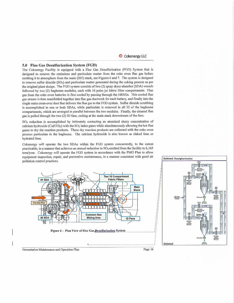
5.0 Flue Gas Desulfurization System (FGD) The Cokenergy Facility is equipped with a Flue Gas Desulfurization (FGD) System that is designed to remove the emissions and particulate matter from the coke oven flue gas before emitting it to atmosphere from the main (201) stack, see Figures 6 and 7. The system is designed to remove sulfur dioxide (S02) and particulate matter generated during the coking process as per the original plant design. The FGD system consists of two (2) spray dryer absorber (SDA) vessels fo llowed by two (2) baghouse modules, each with 16 pulse jet fabric filter compartments. Flue gas from the coke oven batteries is first cooled by passing through the HRSGs. This cooled flue gas stream is then manifolded together into flue gas ductwork for each battery, and finally into the single main cross-over duct that delivers the flue gas to the FGD system. Sulfur dioxide scrubbing is accomplished in one or both SDAs, while particulate is removed in all 32 of the baghouse compartments, which are arranged in parallel between the two modules. Finally, the cleaned flue gas is pulled through the two (2) ID fans, exiting at the main stack downstream of the fans.
S02 reduction is accomplished by intimately contacting an atomized slurry concentration of calcium hydroxide (Ca(OH)2) with the S02 laden gases while simultaneously allowing the hot flue gases to dry the reaction products. These dry reaction products are collected with the coke oven process particulate in the baghouse. The calcium hydroxide is also known as slaked lime or hydrated lime.
Cokenergy will operate the two SDAs within the FGD system concurrently, to the extent practicable, in a manner that achieves an annual reduction in S02 emitted from the faci lity to 6,165 tons/year. Cokenergy will operate the FGD system in accordance with the PMO Plan to allow equipment inspection, repair, and preventive maintenance, in a manner consistent with good air pollution control practices.
ID
Common Gas Mixing Area
Main Stack
ID Fans
. . . , ,, :: '• '• .. :: '• '• ~: '• '• '• '• .. . ,
'• '• .,
!f :: '• '• '• :: '• :: ., ' •
!/ , , '• .. ff ff '•
Figure 6 - Plan View of Flue GasJ)esulfurization System __________________________ }/
Preventative Maintenance and Operation Plan Page 16
Deleted: Dcsulphurizntion
Deleted:
~J Cokenergy LLC
. , .. 1111
L ••••••••••••••• • • • • • • • • • • ••••• • • • • • •• • ••• :-:-.~~'.". •••••••••• -·····i Formatted: Font: 12 pt, Bold
L •••••• • ••• • • • •••••• • . • ••••• • • •••••••• • •• • . ••• •••••••••••••• +_:-:_-_-· >-F_o_r=m=a=tt_e_d_: F=o=n.;,t:_l_l~p=t==- -=----- - =<
Figure 7 - Schematic of Flue Gas Desulphurization System ._F_o_r_m_a_tt_e_d_: C_a...,p_t_io_n ____ _ _ _ ____ _,
~~e [p~~;·~;~e~~;;~~~:-{s~~?~~oy}~~:!~~ :~y~:1~~:;yji~:!h~:~~~~:~:(~~:~f.(~~
~i Cokenergy LLC
Rotary centrifugal atomization is employed for slurry introduction into the hot flue gas. The atomizers are induction motor-driven machines that are designed to operate under high-speed, high temperature, abrasive conditions. Due to these operating conditions, it is critical that the atomizers maintain proper lubrication, cooling, and cleanliness. These conditions are monitored and maintained through the Modicon control system. The atomizer subsystem includes an automatic oil lubrication system, a cooling water system (chiller), and a slurry piping flush system. The rotary atomizers utilize variable frequency drives for start-up, although they are ~10minall~-----· · i~c_o_m_m_e_n_t_ed-'-IC_2.:..1:_? _______ ___ ____J
operated at full speed at approximately 8,000 rpm.
Each Cokenergy SDA vessel is sized to treat up to I 00% of the design flue gas flow from the oven batteries. The SDAs and all downstream equipment may be routinely exposed to corrosive acid gases and wi ll require frequent inspection and maintenance to minimize corrosion and mainta in the integrity of pollution control equipment. Inspections and maintenance wi ll be performed in accordance with Tables 4 and 5 below.
Operational Modes - Single and Dual The SDA units can be operated either in single or dual operational modes. For single operational mode, all flue gas transferred from the oven bat1eries passes through a single SDA vessel, with a single atomizer operating for this vessel. In this mode, the second vessel is isolated using the inlet and outlet guillotine isolation dampers (See Figure 7). In single mode, either SDA - # 1 or #2 -
may be operated.
In dual mode, both SDAs are operated in parallel, with the flue gas from the batteries splitting evenly between each SDA unit, and all isolation dampers in the open position. In dual mode, two atomizers are in operation -one for each vessel. The flue gas is split between the vessels resulting in reduced gas load to each atomizer, and reduced lime and water flows to each atomizer. This also improves spray drying performance because it results in increased residence times for sulfur reaction and increased drying time for the byproduct particulate.
The ability to operate in single mode is critical to allow preventative maintenance of the SDA vessels. Operation in single mode on one vessel allows the other vessel to be isolated and locked out through standard lockout/tagout process, permitting both the atomizer as well as the interior of the SDA vessel to be accessed for inspection and/or maintenance.
Preventative Maintenance and Operation Plan Page 18

it.l Cokenergy LLC
Routine Inspection Requirements Inspection areas for the SDA include not only the SDA vessel itself, but the atomizer and the control and isolation dampers for each SDA. The vessel internals can only be inspected when the SDA is offline, isolated, and locked out. Redundant seal a ir fans (2 per isolation damper) ensure that a man-safe mechanical and air seal are maintained to allow entrance to the vessel.
Table 4 - SDA Inspection Areas
Inspection Scope Eouinment Covered Frequency
Atomizer motor/lower assembly • Atomizer motor • Atomizer operational swap . Atomizer lower assembly • Atomizer motor • Atomizer wheel and tiles maintenance (approx. 6500 . Water and slurry runtime hours)
connections . Atomizer assembly
• Electrical connections maintenance (approx. 4000 . Instrument connections runtime hours)
• Motor/assembly coupling
SDA Vessel • Manway access doors • Annually . Vessel wall interior • Hopper internal walls • Gas scroll ductwork • Scroll flue gas turning
vanes • Inlet distribution control
damoers SDA Vessel and Key Ductwork . SDA vessel and . Monthly or Bi-monthly
ductwork corrosion coupons
Isolation Dampers • Internal seal surface on • Annually isolation side • Damper surface can be . Expansion joint on inspected externally in the insolate side open position as convenient . Seal air fan assemblies
Atomizer Chiller (Cooling Water • Internal seal surface on • Annually Unit) isolation side • Damper surface can be
• Expansion joint on inspected externally in the insolate side open position as convenient
• Seal air fan assemblies Atomizer Lube Oil System • Internal seal surface on . Annually
isolation side • Damper surface can be • Expansion joint on inspected externally in the
insolate side open position as convenient • Seal air fan assemblies
Preventative Maintenance and Operation Plan Page 19
~} Cokenergy LLC
Routine Main tenance Requirements As with inspection, maintenance areas for the SDA include not only the SDA vessel itself, but the atomizer and the conh·ol and isolation dampers for each SDA, as well as ancillary systems (lube oi l and cooling water). The vessel internals can only be inspected when the SDA is offline, isolated, and locked out. Redundant seal air fans (2 per isolation damper) ensure that a man-safe mechanical and air seal are maintained to allow entrance to the vessel.
Table 5 - SDA Maintenance Areas
Maintenance Scone Eauinment Covered Freauencv Atomizer motor ____________ .......... . • ___ Atomizer motor ···-· -·-· ··
-• ··· t:::r~~!~~~l~~~~~le ::::::: • Electrical connections • Instrument connections runtime hours max
• Mechanical seal • Timing may vary . Bearings depending on operational
• All OEM-identified wear loads and conditions
parts
Atomizer lower assembly ·····-··· . • ... Atomizer.wheel,.ti les, .. . • ... Approx. 4000.nmtime ·-·-· .. and nozzles hours nominal, 7500 . Water and slurry runtime hours max connections . Timing may vary . Instrument connections depending on operational
• Spindle assembly loads and conditions
• Bearings . Lower "spider" water and lime distributor assembly
• Air vent SDA Vessel and Ductwork -= --------------------------------------- . • ... Manway access.doors ..... . • ... As required . . .................
• Vessel wall interior . Hopper internal walls
• Gas scroll ductwork • Scroll flue gas turning
vanes • Inlet distribution control
dampers • Exnansion ioints
,Atomizer Chiller (Cooling Water -· _• ... Filters ·······-·············- . • ... Quarterly·················-----Unit) . Glycol reservoir/supply . Compressor ,Atomizer Lube Oil System··--·--·-- _• ... Pum.11 .......... ·-·--·---· ···· . • .. _Quarterly ......................
• Solenoid • Clean oil reservoir
l~9J~.t!9!! .1?.an1p_e.r.~ ... --------------- . • ... Damper internal flex seal. _• .... As required ... . . ..... ......... assembly . Expansion joint
• Seal air fan assemblies
Preventative Maintenance and Operation Plan Page 20
Formatted: Highlight
Formatted: Highlight
·-. Commented [C3J: Need triggers for repair ·-.. l----...;.. ___ ....;. __ ...;.._~---<
Format ted: Highlight
_ ... •·· { Formatted: Highlight
__ .. . •· { Formatted: Highlight
__ ... •·{ Formatted: Highlight
..-·-··1 Formatted: Highlight
. .. -·-·1 Formatted: Highlight
~} Cokenergy LLC
It must be noted here that, due to the original design of the MET SDA equipment, there are certain areas that cannot be individually isolated; therefore, they cannot be inspected or maintained internally unless the entire FGD system is oftline.
These areas include:
• The inlet flue gas ductwork to the SDAs upstream of the inlet guillotine isolation dampers; • The SDA outlet ductwork downstream of the SDA outlet guillotine isolation dampers;
• The expansion joints in the noted ductwork.
These areas were last inspected during the May 2015 FGD outage. Inspections of the areas listed above shall be conducted during each scheduled maintenance. unless previously inspected within
XX years.
5.2 BAGHOUSE
The Baghouse is located downstream of both SDAs and is designed to remove particulate material from the flue gas, and is a standard pulse jet fabric filter design. A small portion of the collected particulate is carried from the coke oven process, but the majority of the particulate is formed as a byproduct of the SO2 removal process. Removal of the particulate matter is accomplished via filter bags arranged in modules that are installed in the flow path between the SDA and the ID Fans. The baghouse consists of 32 filter compartments arranged in two parallel modules of 16 compartments each (I A- 1 P, 2A-2P). Each compartment is equipped with 272 bags, each with a diameter of 6 inches and a nominal length of about 16.33 ft. In normal operation, flue gas flows to each of the baghouse compartments. As the flue gas passes through the filter bags, particulate accumulates on the outside of the filters and cleaned flue gas exits the baghouse compartments and then continues through the ID fans to the stack. The filter bags are rated to operate continuously at temperatures up to 320°F with short-term excursions ofup to 400°F. ,G_<!S_!~~P.~!'.<!!~~~-s _t_(!_t~~------ --fLo_e_le_t_ed_: _ ____ ________ __, baghouse are controlled through dilution water cooling introduced though the SDA atomizers, maintaining mixed gas temperature to the baghouse in the range of250°F -280°F.
Filter bags are a PPS needle felt fabric, typical for the baghouse industry, which is then dipped in a PTFE emersion bath to improve characteristics of particulate penetration and release. When installed, filter bags are cleaned using a distributed pulsed a ir system, again typical for industrial fabric filter baghouses. Pulse cleaning for the baghouse compartments are completed on an automated offline cycle. This automated program cycles through the 16 individual compartments in a module when the gas-side pressure drop on a given module reaches a defined target maximum, rominalll~~U~!'_?_.J _i_~~-~~~-~ c;, __ _______ __ _____ ______ ___ ___ ____ ______ __________ ___ ___ __________ __________ _____ ____ .- -fLc_o_m_m_e_n_te_d_c[:._C4-')=--: -? _ _________ _,
It is possible during normal operation to remove 1-2 compartments from service from each baghouse module to allow these compartments to be isolated for interna~ maintenancq._ __________ ____ _ .----{ Commented [CS): Triggers for repair?
Inspection Requirements Several routine inspection tasks are periodically executed for the baghouse. The primary inspection is a quarterly inspection of all 32 baghouse compartments each year by a third-party company experienced with pulse jet fabric filter design, equipment, and operation. This
Preventative Maintenance and Operation Plan Page 21
~'). Cokenergy LLC
inspection is completed by systematically taking 1-2 compartments offline, isolating and locking out each compartment, followed internal inspection by an experienced crew .
• Th~. 4_l!~!.t~_r_l)'. _i_Il~R~~t_i~11-~-~~~~~-~~-~~~-~-C>~_l.!11:!':Il!~: _____ ........... ______ _______ .. __________ .... ___________ ____ ... -- -{ Deleted: - ----- - ---- - - - Page Break - - ---- - - ---- -- ]
• Filter bag condition for all compartments; • Filter cage condition for all compartments; • Compartment clean gas-side condition for all compartments; • Compartment dirty gas-side condition, including the compartment hopper, for a portion of
the total - typically 8 of 32.
During this compartment-by-compartment inspection, if a filter bag and/or cage is found to be damaged, it is documented, and then replaced. The contractor completing the inspection documents results for all compartments, including any compartments exhibiting damage or unexpected conditions.
Maintenance Requirements Accessible Components/ Areas The following maintenance tasks are routinely completed through normal subsystem deenergization and lockout/tagout process. • Annual replacement of filter bags in the eight compartments with the longest runtime since the
last filter bag change-out. This process is completed yearly since the PTFE-coated PPS filter bags in use at Cokenergy have been found to have a 3-4 year life cycle for the flue gas conditions experienced at Cokenergy (primarily flue gas oxygen levels combined with gas temperature levels). This annual process replaces the oldest set of filter bags to provide a systematic replacement process that can be scheduled and budgeted year-to-year.
• Replacement of baghouse compartment hopper swing disc assemblies, due to wear part deterioration with use. Swing discs provide the means to evacuate the calcium sulfate byproduct from a compartment hopper fo llowing a given number of pulse cleaning cycles. The swing discs are part of each baghouse compartment, and due to the fine, erosive nature of the byproduct particulate, require replacement of key moving wear parts on a 6-12 month average basis to remain in good working order. This is accomplished by swapping a swing disc at the end of its operational cycle with a spare rebuilt disc in inventory.
• Periodic - and typically long-term - repair of internal and/or external compartment weld cracking or localized corrosion locations to maintain air-tight seal and avoid infiltration of
ambient air.
Inaccessible Components/ Areas It must be noted here that, due to the original design of the MET baghouse equipment, there are certain areas that cannot be individually isolated, therefore they cannot be inspected or maintained internally unless the entire FGD system is offline.
These areas include: • The inlet flue gas ductwork between the SDA outlet guillotine isolation dampers and the
inlet the baghouse module; • The dirty flue gas distribution plenum to the compartments for each module;
Preventative Maintenance and Operation Plan Page22
~} Cokenergy LLC
• The clean flue gas collection plenums from the compartments for each module;
• The inlet damper assemblies for each compartment; • The outlet poppet dampers for each module; • The downstream ductwork from the baghouse outlet to the inlet guillotine isolation damper
for each ID fan; • Turning vanes in each of the ductwork areas mentioned above.
Pue to lack of access, and inability to isolate while the FGD is in operation, these areas are not routinely inspected. Internal damage in these areas would require a full plant outage to access and repair. It should be noted that these areas were last accessed and inspected in the planned full plant outage in May 2015. Duct and turning vane repairs identified in these areas were repaired at that timej These inaccessible areas and C_<)!JIJ20nents wi II be ins12ected everx XX ye_~rs. _. __ . __ . ______________ . -- - Commented [CG]: Estimate timelines for the next full
plant outage, identify timelines for inspection and repair for
these areas.
5.3 INDUCED DRAFT FANS
The Induced Draft (ID) Fans provide the motive force to draw flue gas from the coke ovens, through the 16 HRSGs, SDAs, and baghouse compartments, and discharge the gasses out a common exhaust stack. The facility is equipped with two ID fans, s ituated in parallel downstream of the baghouse modules. The fans are connected by a common header downstream of the baghouse modu les so that the fans may operate in tandem, or either single fan may operate and handle flue gas flow from both baghouse modules while the other fan is isolated. The original equipment supplier is TL T-Babcock. OEM support for the fans is now provided through Howden.
The fans are designed for an inlet flue gas flow of605,090 scfm with an inlet temperature ofup to 300°F, with short-term excursions at up to 500°F. The two fans are installed in parallel and are each equipped with two inlet ducts and one discharge duct. The fans discharge into a common header that directs the flue gases to atmosphere through a single exhaust stack. Motor operated isolation dampers are installed upstream and downstream of each ID fan providing positive isolation for maintenance.
During operation both the inlet and outlet isolation dampers are fu lly open and the inlet louver control dampers modulate to adjust flow through the fans and draft to the upstream portions of the Cokenergy and II-ICC facility. During normal operation, both fans are in service.
Each fan is equipped with an identical, independent, lube oil system, used for lubricating the fan bearings. The lube oil system is equipped with two motor driven pumps, one for operation and the other for redundant standby.
Each fan is driven by a 7500 HP, 13.8 kV AC motor. Each motor is equipped with a fixed bearing located between the motor and the fan. The motor is equipped with shaft mounted fans that circulate air to cool the motor windings as it operates. The fan housing is equipped with air filters that prevent dust and contaminants from entering the motor with the circulating cooling air flow. A differential pressure switch (PDS) is installed and will provide an alarm indicating that the filters require service.
Preventative Maintenance and Operation Plan Page 23
ti Cokenergy LLC
For further redundancy, a spare ID fan motor is maintained in " ready-to-install" condition in environment-controlled storage operated by the motor repair vendor. This fan can be transported to the plant for installation within one day, with swap out of motors typically taking two days.
Routine Inspection Requir'emcnts Several standard inspection tasks are routinely completed for the ID fans. However, internal inspections can only be completed when the fan is offline, isolated and locked out. These are
,comp1eted _ once a year, or_ as !possibl( OEM or third-party inspection _of the _ID _fan internals _will , --.--
)?<::_~_<?!1:IP.!~!<::!-!_<?!1..f'.iX~~X~ar_~).'~_I~~ The _l_~~t_i_n~11ection o_op_ f~n_!t)J<::1:~~-I~ was _1:~111p_l~~~~-)!1. -~9_\ ?_· __ ----.. ·- -
Internal inspection tasks, when possible,~_j1_1_(:[t1!-!~,----------------------·--------- ----------------------, '\---• Inspection of inlet scroll section \ \
• Inspection of rotor \_
• Inspection of all guide and turning vanes
• Inspection of motor electrical connection cabinet
• Inspection of motor windings and cable connections
• Inspection of lube oil units
Commented [C7]: Identify potential problems and proposed solutions, with timelines.
Deleted: nominally
Deleted: nominally
Deleted: , with the
Deleted: would
·External inspections~ completed_as_part of normal daily/weekl_Y._walkdowns: -------------------------{ ___ D_ e_l_et_e_d_: a_re_typ;:_:_ic_a_lly'---------- ---'
• Visual external inspection of lube oil units
• Visual inspection of louver damper linkage
• Visual inspection of all external casing and electrical cabinets
Routine Maintenance Requirements Preventative maintenance for the ID fans primarily focuses on routine external maintenance of the
ID fan motors and lube oil skids.
Routinely scheduled preventative maintenance~hall_include: --------------------------------------------- --- -- -- Deleted: includes \===--=--~=--====--!.
• Replacement of ID fan motor air filters, at least on a quaiierly basis,. __ ~1J_t alsq_y!'!~~l_l_jndicated _.----- Deleted: or ill:'. filter pressure drop; _______________ _____ ______ ____________________________ __ ________________ ___ _____________ :·---. >-D- e-le-t-ed_:_w-it-h------------ -:
• Maintenance of oil level and condition of the ID fan lube oil skids. ·
Internal ID fan maintenance and repairs if necessary would be coordinated with the appropriate OEM or experienced third-party vendors. In the event of an ID fan motor failure, the standby motor would be requested from the storage facility, the out-of-service motor would be disconnected and lifted from the motor pedestal, and the standby motor would be installed in its place. The failed motor would be sent to the motor repair vendor, and once repaired, returned to
storage as the new standby unit.
5.4 CONTROL SYSTEM
The control system for the FGD system is a Modicon PLC system, manufactured by OEM Schneider Electric. This system consists of a Primary and Secondary (Hot Standby) redundant controller and twelve (12) Remote input/output (1/0) racks. The Modicon controls the facility's ID Fans, Baghouse, Spray Dryer Absorbers, and FGD auxiliary support systems. The Modicon
Preventative Maintenance and Operation Plan Page 24
Deleted: indication
~} Cokenergy LLC
control system is the original FGD control system, but components were upgraded in 2015. Improvements implemented in the upgrade include new controllers along with replacement of obsolete coaxial communication cables to remote 1/0 locations. New controllers have enabled improvements to automation software as prior to 2015, the original controllers were fully utilized, preventing programing and automation enhancements. Remote 1/0 communication coaxial nonredundant cables were replaced with redundant, self-healing, fiber optic cables.
The Modicon configuration diagram, Figure 8, shows the current configuration of this system. Racks IA and 1B are the Primary and Hot Standby Controllers (CPU). Racks two through twelve are spread out through the facility as remote 1/0 racks controlling their designated descriptions. Redundant fiber optics cables provide reliable means of communications to these racks. In addition, multiple human machine interfaces (HMI) provide redundancy for operations to run the
facility.
It is important to note that the FGD control system plays a key role for overall availability and reliability of the Cokenergy plant. If the control system would fault on both PLC controllers, all FGD controls would be inoperative, including both ID fans. If the ID fans are not maintaining draft through the flue gas system, then flue gas is not pulled through the HRSGs or through the FGD system. Without flue gas, all HRSGs are offline, with II-ICC stack lids opening automatically to maintain natural draft to the ovens. Because of this requirement maintenance of the Mod icon PLC system has high importance.
The Modicon OEM recommendsJ]_~c!_Cokene~gy will follow t)1e_p_~~Y-~1:}_t!3_t_i}'.~_ffi._!!\1:!~~-~~.'!~~--t~~~_s ___ _____ i Deleted: tl1e following for the FGD PLC control system listed below: '--------"'------- - ---'
• Maintenance of daily operating system back-ups for the PLC controllers, in the event one unit experiences a fault and must be reloaded;
• Firmware upgrades, as available and provided by the OEM; • Programming software updates, as available and provided by the OEM; • PLC processor memory optimization, periodically per OEM recommendations.
The first three of these preventative maintenance activities can be completed with the redundant PLC system on-line, working between the primary and secondary PLC controllers. This allows the PLC to be updated with operational system updates as the OEM identifies and develops revisions. Cokenergy follows these guidelines to ensure system reliability.
The final maintenance recommendation requires that both primary and secondary PLC controllers be taken offline for the optimization process. The OEM recommends this optimization after s ignificant software, programing, and/or hardware upgrades are completed on the Modicon. Because of on-going system improvements lo both hardware and automation programing, Cokenergy anticipates the need to complete an optimization process approximately every two years. This requirement will continue to be evaluated in coordination with the OEM, due to its implications on venting and SO2 compliance. and the PMO Plan will be updated as needed to
reflect changes in the optimization process.
Preventative Maintenance and Operation Plan Page 25
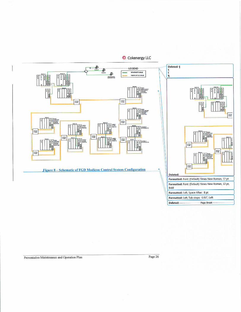
figure 8
t:t Cokenergy LLC
Schematic of FGD Modicon Control Svstem Configuration ---------- .:":. •' ,, •'
\\ \ \ \\ 'I ' I ,, :j ,, ,,
Deleted: 'I 'I 'I 'l
:: Deleted:
\ •'
Formatted: Font: (Default) Times New Roman, 12 pt
Preventative Maintenance and Operation Plan Page 26
•,', •', '• ' •
Formatted: Font: (Default) Times New Roman, 12 pt,
"'-', •, )--------------~ \'•,r-Fo_r_m_a_tt_e_d_: _Le_ft_, ..;Sp:..a_c_e_A_ft_e_r:_8..;p:..t-------~
Bold
Formatted: Left, Tab stops: 0.95", Left
Deleted: --- -- - --- - ----Page Break- - ---- ---- - - - -
~'). Cokenergy LLC
6.0, Continuous Emissions Monitoring.System(CEMsL ..... ................. ........... /··· f.___D_el_et_ed_:_<N_>-'-~---- -------'
Pursuant to Section D.1.9 of Cokenergy's Title V permit, the concentrations of SO2 and 0 2 must be monitored from the stack and the SO2 emission rate from the main slack. Cokenergy must provide the output from the CEMS to !HCC fo r utilization in the emission tracking system. Opacity monitoring is required in accordance with Section D.1.10 of the permit. In accordance with paragraph 19 of the CD, Cokenergy has installed a permanent flow monitor to measure the
volumetric flow rate of the main stack.
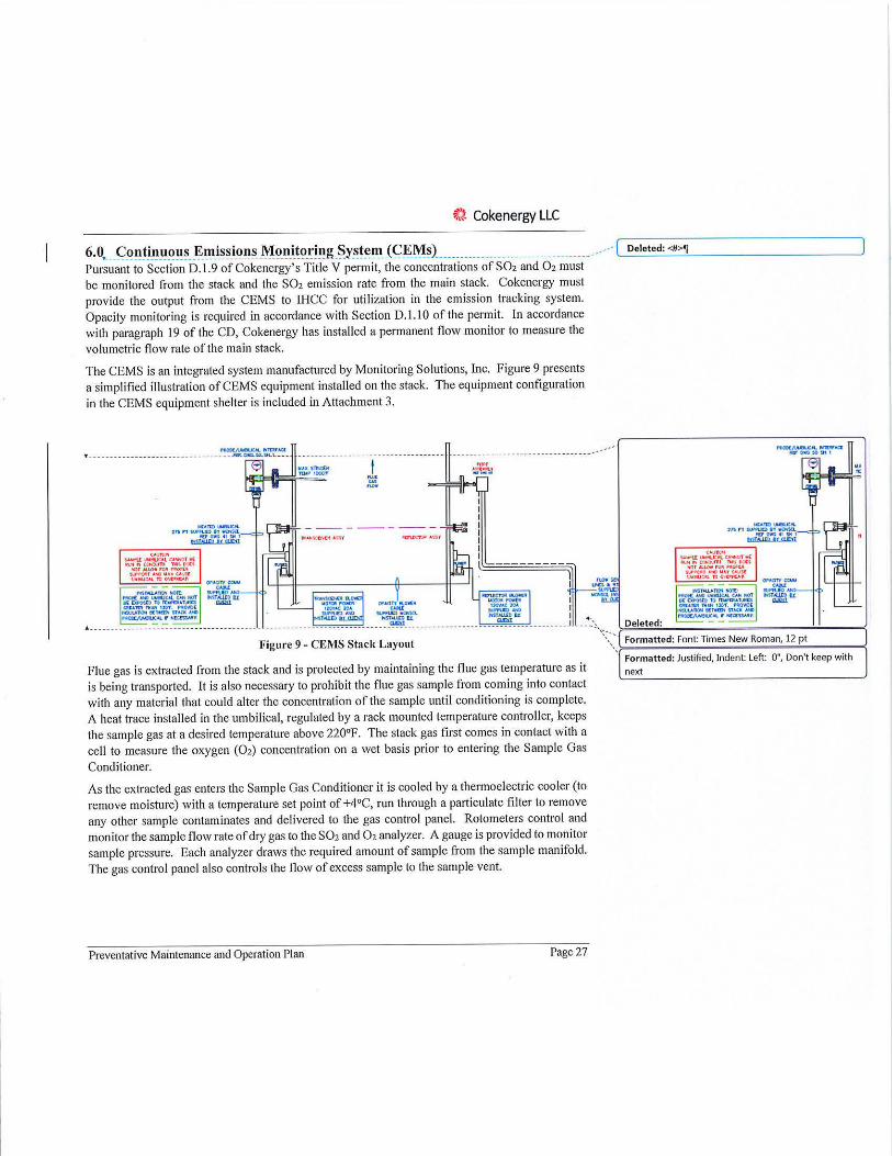
The CEMS is an integrated system manufactured by Monitoring Solutions, Inc. Figure 9 presents a simplified illustration of CEMS equipment installed on the stack. The equipment configuration in the CEMS equipment she lter is included in Attachment 3.
T----------••••-- -- ---------- --- -~~~~- ----------------------------------·
,c,,m,-,c,,. 1,snllA'f\.lCl)lllillCt•i'.a..
MJ'OllG ◄I SNI
b:5Uf1m tx men ~ ,.n ,
'''°' ·~-,
, ... .....
... ,.._..._ :nn9'ftJCll'1~
,0(1-.;~SN I tiiSIHlcP It urn
., "
Figure 9 - CEMS Stack Layout .. :', ,,;:,·,,·,>-D- e- l-et_e_d_: ---------------- -< Formatted: Font: Times New Roman, 12 pt
Formatted: Justified, Indent: Left: O", Don't keep with
next Flue gas is extracted from the stack and is protected by maintaining the flue gas temperature as it is being transported. It is also necessary to prohibit the flue gas sample from coming into contact with any material that could alter the concentration of the sample until conditioning is complete. A heat trace installed in the umbilical, regulated by a rack mounted temperature controller, keeps the sample gas at a desired temperature above 220°F. The stack gas first comes in contact with a cell to measure the oxygen (02) concentration on a wet basis prior to entering the Sample Gas
Conditioner.
As the extracted gas enters the Sample Gas Conditioner it is cooled by a thermoelectric cooler (to remove moisture) with a temperature set point of +4°C, run through a particulate filter to remove any other sample contaminates and delivered to the gas control panel. Rotometers control and monitor the sample flow rate of dry gas to the SO2 and 02 analyzer. A gauge is provided to monitor sample pressure. Each analyzer draws the required amount of sample from the sample manifold. The gas control panel also controls the flow of excess sample to the sample vent.
Preventative Maintenance and Operation Plan Page 27
~, Cokenergy LLC
COMS (Continuous Opacity Monitoring System) - monitors the opacity of particulate flowing through a stack or duct. The system measures opacity as a percentage of light passing through the gases compared to the reference light beam originating from source. It consists of four major components: the Transmissometer, the terminal control box, the air-purging system and the remote-control unit and data acquisition equipment. The Transmissometer component consists of an optical transmitter/receiver (transceiver) unit mounted on one side of a stack or duct and a retro reflector unit mounted on the opposite side. The transceiver unit contains the light source, the photodiode detector, and the associated electronics. The transceiver uses a single-lamp, single detector system to determine opacity. An LED light source is modulated electronically at 2 KHz to eliminate any ambient light interference. The modulated beam is configured to alternately produce reference and measurement signals so that the effects of variations in the optical and electronic components of the opacity monitor are minimized.
The display terminal control box mounted beside the transceiver unit provides on-stack readout of the opacity output from the transceiver and can be used as a diagnostic tool.
The air purging system serves a threefold purpose: 1) it provides an air window to keep exposed optical surfaces clean; 2) it protects the optical surfaces from condensation of stack gas moisture; and 3) it minimizes thermal conduction from the stack lo the instrument. A standard installation has one air-purging system for each of the transceiver and the retro reflector units. The remotecontrol unit communicates with the remote display unit via an RS 422 cable.
CEMFlow - A simple S-type pilot tube is utilized to measure differential pressure as gas flows up the stack. High and low pressure is measured, then utilized to calculate stack velocity (using the Bernoulli equation). Multiplying by the stack diameter converts this velocity to flow. The stack gas temperature is also monitored using a standard thermocouple.
CEMCON (Continuous Emission Monitoring Controller System) - receives and stores data generated by the CEMS and automatically controls CEMS operations such as system purge, sample air flow, calibration, and detection of alarm conditions. In addition, it provides the communication link between CEMS and CEMDAS. The CEMCON system consists of a PLC controller with power supply and a multifunction keypad for operator interface.
CEMDAS (Continuous Emission Monitoring Data Acquisition System) - retrieves the data stored by the CEMCON and performs the required calculations to determine if the readings are within required limits. The system is designed to provide alarm messages and signals in the event the results do not meet applicable requirements. CEMDAS can also generate the required reports used in EPA audits and in evaluating system operabi lity.
The emissions monitoring equipment surveillance and maintenance requirements are included in the site QA/QC plan.
Preventative Maintenance and Operation Plan Page 28
lit) Cokenergy LLC
Emissions Tracking System (ETS) In order to calculate SO2 emissions from the Indiana Harbor Coke Company (IHCC) emergency vent stacks and calculate the combined SO2 emissions from !HCC and Cokenergy; IHCC utilizes ETS. The ETS system utilizes coke production data, HRSG steam production, vent lid status, and coal analytical data to calculate the potential SO2 emissions from venting using a material balance. Cokenergy provides actual sulfur dioxide data from the stack CEMS to allow for the calculation of site SO~emissioni 911 a XX bas[s'-tJ~e_ CEMS reading_s at the main S!ack wil! be_ com12ared to , -- -- -ETS projections at the bypass stacks to verify the accuracy of the data upon which ETS calculations \ -~- \ With the addition of the flow monitor on the Cokenergy stack (20 I), the IHCC ETS system is in the process of being updated pursuant to paragraph 21 of the CD. Once complete the SO2 emission will be calculated using the actual stack flow rate.
7.0 Emissions Minimization Efforts with IHCC Because of the close dependence between the two plants, there is a need for daily communication between the two plants at multiple levels so that maintenance activities can be coordinated, and forced outage events can be more efficiently and quickly resolved. Cokenergy will make every effort to coordinate with II-ICC and conduct required maintenance during scheduled bypass venting
events.
In the event of bypass venting in excess of the daily venting limit of 19%, Cokenergy, working in conjunction with IHCC, will minimize emissions to the extent practical as set forth in paragraph 17 of the Consent Decree.
8.0 Electrical Conditions and Responses to Electrical Distribution Failures at AM
The AM Indiana Harbor integrated steel facility, the IHCC metallurgical coke plant, and Cokenergy form an interconnected electrical distribution system. This is important to note for this plan because changes to the electrical conditions outside of Cokenergy can impact the operation and availability of Cokenergy's equipment.
Cokenergy is interconnected with the AM Indiana Harbor electrical distribution grid by two 69kV transmission lines - 2RX04 and 2RS03. These supply redundant power to the Cokenergy facility, and are each stepped down to 13.8kV to supply the full Cokenergy facility equipment on two 13.8kV bus lines. If one of these 69kV lines is down, the internal tie breaker between the two bus lines can be closed to power both sides of the bus, maintaining power to the entire Cokenergy plant. Power generated by Cokenergy's steam turbine generator similarly is stepped up from 13.8kV to 69kV and is supplied to the AM Indiana Harbor grid by 2RS03.
If both of the 69kV bus line are down, due to issues with the AM Indiana Harbor electrical grid, then the Cokenergy facility will be without operating power and all equipment will be offline.
Preventative Maintenance and Operation Plan Page 29
Commented [CB]: How often will Cokenergy check to make sure t he ETS Is properly reporting emissions from the
bypass stacks? That is, how often are projections from the ETS checked against readings from the CEMS, to ensure accuracy of ETS calculations? Every month, eve ry week ... ?
Deleted:.
Deleted: <#> Events Outside of Cokenergy Controllj
~l Cokenergy LLC
Because power to IHCC is supplied through the Cokenergy 4160V bus lines to IHCC, this will
also mean that !HCC is also without operating power.
It is important to note that the Cokenergy facility is not configured electrically to operate as an independent electrical "island" within the AM Indiana Harbor electrical grid. This means that even if all Cokenergy equipment and systems are in operational order, if electrical supply from the AM Indiana Harbor grid fails, Cokenergy faci lity will be offline until power can be restored to at
least one of the 69kV bus lines.
This failure in electrical distribution has occurred a limited number of times in recent years due either to (I) lightning strikes on key AM electrical grid components, or (2) equipment failure on
key AM electrical grid components - typically transformers.
Under these circumstances, Cokenergy will follow these standard protocols:
( I) Cokenergy management remains in regular communication with AM Utilities counterparts to best coordinate return-to-service activities;
(2) Cokenergy management remains in regular communication with IHCC counterparts to best coordinate return-to-service activities;
(3) Cokenergy staff prepares all equipment, and if necessary makes required repairs, to allow best possible return-to-service time, with emphasis on environmental control systems;
(4) For long duration events, Cokenergy will d iscuss and coordinate emissions minimization
efforts with IHCC.
9.0 PMO Plan Management and Revisions Per the Consent Decree, Cokenergy and !HCC have agreed to implement a Compliance Assurance Plan (CAP) in the PMO Plans to address potential periods of higher production levels. !HCC is responsible for monthly evaluation of production and sulfur content of dry coal to identify when they exceed both of the levels indicated in the following chart in two consecutive months.
1g 1 ro ucflon " H' h P d eve ont s L IM h"
Average Between 0.7% Monthly Sulfur Content of Dry Coal >0.9%
and 0.9%
Average Monthly Tons of Dry Coal Charged 144,000 128,000
JHCC and Cokenergy will jointly evaluate whether subsequent High Production Level Months could cause exceedances of PM or SO2 limits in the Companies' Permits and the Consent Decree, and if so, the steps that will be taken to prevent those exceedances. Cokenergy is responsible for evaluating the CAP actions related to operability and control of the FGD and I-IRSG equipment. The CAP is required to be submitted once prepared or updated and for any instance when the CAP had to be implemented to ensure compliance with PM or SO2 limits.
Any update to the PMO Plan or fai lure to follow gu idelines identified in the PMO Plan will be reported to USEPA and IDEM in a semi-annual progress report.
Preventative Maintenance and Operation Plan Page 30
if.} Cokenergy LLC
,PMO _PLAN REVISION _HISTORY --- --------------------------- ---- ---------- ___________ _________ ___ _____ ___ •·,-:<_ ~eleted: - -------------Page Break ------------- -1
Formatted: Indent: Left: O", Space Before: 0 pt, After: 8 pt, Widow/Orphan control
Revision # Date Description of C hange Approved By
0 6/28/2018 Initial plan development 'D. Pacli.
Preventative Maintenance and Operation Plan Page 3 1

~i Cokenergy LLC
Attachment 1 - HRSG Cleaning Procedure
Preventative Maintenance and Operation Plan Page 32
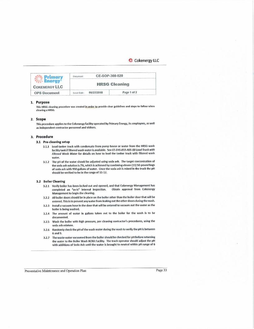
~} Cokenergy LLC
~,~ Primary noc.urnen1 CE-SOP-300-020
1~ Ene,vy HRSG Cleani ng
COKENERGY LLC
OPS Document Issue Date 06/27n018 I Page 1 or2 ~ --- --- -----
1. Purpose l his HRSG cleaning procedure was created Jn.smi~.{.l~ provide clear guidelines and st<!ps to follow when cleaning a HRSG.
2. Scope This procedure applies to the Cokenergy facility operated by Primary Energy, its employees, as well
as independent contractor personnel and visitors.
3. Procedure 3.1 Pre-cleaning setup
3.1.1 Load tanker truck with condensate rrom pum1> house or water f rom the HRSG wash
facility tank if filtered wash water is available. See CE·EHS-833-AOS-OO t oad Trvck with Filte,ed Wash Water for details on how to load the tanker truck with filtered wash
water. 3.1.2 The pH of the water should be adjusted using soda ash. The target concentration or
the soda ash solution is 7%, which is achieved by combining eleven (11) SO-pound bags of soda ash with 950 gallons of water. Once the soda ash Is mii ed in the truck the pH should be verified to be in the range of 11-12.
3.2 Boller Cleanlng 3.2.1 Verily boiler has been locked out and opened, and that Cokenergy Management has
completed an "as-ls" Internal inspection. Obtain approval f rom Cokenergy Management to begin the cleaning.
3.2.2 All boiler doors should be in place on the boiler other than the boiler door that will be entered. This is to prevent any water from leaking out the other doors during the wash.
3.2.3 Install a vacuum hose in the door that will be entered to vacuum out the water as the boiler is being washed.
3.2.4 The amount of water in gallons taken out to the boiler for the wash i s to be
documented.
3.2.5 Wash the boiler with high pressure, per cleaning contractor's procedures, using the
soda ash mixture.
3.2.6 Randomly check the pH ol the wash water during the wash to verify the pH Is between
6 and 9.
3.2.7 The waste water vacuumed from the boiler should be checked for pH before returning the water to the Boller Wash RCRA Facility. The truck operator should adjust the pH with additions of Soda Ash until the water is brought l o neutral within pH range of 6
Preventative Maintenance and Operation Plan Page 33
~) Cokenergy LLC
.:?'~ Primary ~~ ergy•
C oKENERGY LLC
DDClUne-nt CE-SOP-300-020
HRSG Cleaning
OPS Document ISSlk! Dale 06/27/2018 Page 2 of 2
and 9.
3.2.8 Once pH Is verified In accordance with 3.2. 7 above, transfer the waste boiler wash waler lo the Boller Wash RCRA Facility. Unload the waste wash water at the facility In accordance with EHS Procedure CE,EHS·B33·A01•00 Boiler Wash RCRA Facility• Appendi1< 1 Unload Truck to 1-/azordous Waste Dewoterino 801<.
3.2.9 Prior to final rinse, the HRSG Area Manager or designate will complete an inspection of clean condition to verify the wash is comple te.
3.2.10 Final rinse of the entire boiler and economizer with pure water Is done once the Initial wash is completed and inspected by Cokenergy Management.
3.2.11 Once the boiler wash has been completed and all the waste water has been transferred to the Boiler Wash RCRA Facility, the amount of the waste wash water re turned to the facility is to be documented. This is to detormine how much of the water that was used for the boile r cleaning has been recovered.
4. Implementation
4.1 This procedure is effective upon the issuance date and upon any subsequent revisions.
5. E,cceptlons and Variances
5.1 Any variances to this Standard must be authorized by the General Manager. Designates may be appointed to cover during absences. This approval may be electronic or in hard copy form.
6. Document Control
REVISION HISTORY
Revision Date Description or Change Written by Approved By #
01 06/27/2018 Approve Final Revisions R. \Vl'(M'IOl½' 1(. l(~>U\,t'\,
Distribution
Electronic Coples S: Job Procedures\liRSGS\ R: Latest Procedures
Paper Coples none
Document Responsibility
owner R. Wranosky
Preventative Maintenance and Operation Plan Page 34
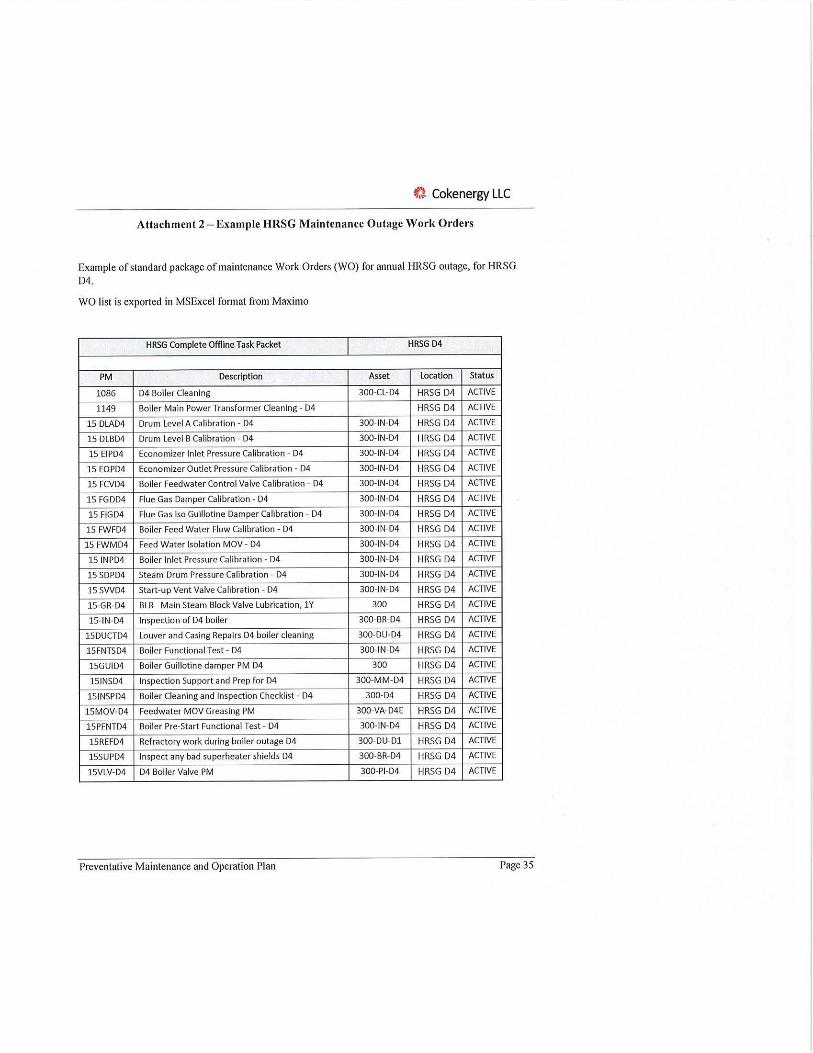
~} Cokenergy LLC
Attachment 2 -Example HRSG Maintenance Outage Work Orders
Example of standard package of maintenance Work Orders (WO) for annual HRSG outage, for HRSG 04.
WO list is exported in MSExcel format from Maximo
HRSG Complete Offiine Task Packet HRSG D4
PM Description Asset Location Status
1086 D4 Boiler Cleaning 300-CL-D4 HRSG D4 ACTIVE
1149 Boiler Main Power Transformer Cleaning - D4 HRSG D4 ACTIVE
15 DLAD4 Drum Level A Calibration - D4 300-IN-D4 HRSG D4 ACTIVE
15 DLBD4 Drum Level B Calibration - D4 300-IN-D4 HRSG D4 ACTIVE
15 EIPD4 Economizer Inlet Pressure Calibration - D4 300-IN-D4 HRSG D4 ACTIVE
15 EOPD4 Economizer Outlet Pressure Calibration - D4 300-IN-D4 HRSG D4 ACTIVE
15 FCVD4 Boiler Feedwater Control Valve Calibration - D4 300-IN-D4 HRSG D4 ACTIVE
15 FGDD4 Flue Gas Damper Calibration - 04 300-IN-04 HRSG D4 ACTIVE
15 FIGD4 Flue Gas Isa Guillotine Damper Calibration - D4 300-IN-04 HRSG D4 ACTIVE
15 FWFD4 Boiler Feed Water Flow Calibration - D4 300-IN-04 HRSG D4 ACTIVE
15 FWMD4 Feed Water Isolation MOV - D4 300-IN-04 HRSG D4 ACTIVE
15 INPD4 Boiler Inlet Pressure Calibration - 04 300-IN-D4 HRSG D4 ACTIVE
15 SDPD4 Steam Drum Pressure Calibration - D4 300-IN-D4 HRSG D4 ACTIVE
15 SVVD4 Start-up Vent Valve Calibration - 04 300-IN-D4 HRSG D4 ACTIVE
15-GR-D4 BLR Main Steam Block Valve Lubrication, lY 300 HRSG D4 ACTIVE
15-IN-D4 Inspection of 04 boiler 300-BR-04 HRSG D4 ACTIVE
15DUCTD4 Louver and Casing Repairs 04 boiler cleaning 300-DU-04 HRSG D4 ACTIVE
15FNTSD4 Boiler Functional Test - 04 300-IN-D4 HRSG D4 ACTIVE
15GUID4 Boiler Guillotine damper PM 04 300 HRSG D4 ACTIVE
15INSD4 Inspection Support and Prep for 04 300-MM-D4 HRSG D4 ACTIVE
15INSPD4 Boiler Cleaning and Inspection Checklist - D4 300-04 HRSG D4 ACTIVE
15MOV-D4 Feedwater MOV Greasing PM 300-VA-D4E HRSG D4 ACTIVE
15PFNTD4 Boiler Pre-Start Functional Test- 04 300-IN-04 HRSG D4 ACTIVE
15REFD4 Refractory work during boiler outage D4 300-DU-Dl HRSG D4 ACTIVE
15SUPD4 Inspect any bad superheater shields 04 300-BR-04 HRSG D4 ACTIVE
15VLV-04 04 Boiler Valve PM 300-PI-D4 HRSG D4 ACTIVE
Preventative Maintenance and Operation Plan Page 35

t} Cokenergy LLC
Attachment 3 - CEMS Shelter Layout
Preventative Maintenance and Operation Plan Page 36