ATV71 communication parameters EN 1755861 08 Parameters Manual ... The PowerSuite software workshop...
139
1755861 www.schneider-electric.com 2354235 11/2008 Altivar 71 Communication parameters User manual Software V5.7 02/2013
-
Upload
duongxuyen -
Category
Documents
-
view
227 -
download
0
Transcript of ATV71 communication parameters EN 1755861 08 Parameters Manual ... The PowerSuite software workshop...

2354235 11/2008
1755
861
www.schneider-electric.com
Altivar 71Communication parameters
User manualSoftware V5.7
02/2013

Contents
Document structure and directions for use__________________________________________________________________________ 5Presentation _________________________________________________________________________________________________ 7Software enhancements________________________________________________________________________________________ 9
Enhancements made to version V1.2 in comparison to V1.1 _____________________________________________________ 9Enhancements made to version V1.6 in comparison to V1.2 ____________________________________________________ 10Enhancements made to version V2.5 in comparison to V1.6 ____________________________________________________ 10Enhancements made to version V2.7 in comparison to V2.5 ____________________________________________________ 10Enhancements made to version V5.7 in comparison to V3.3 ____________________________________________________ 11
Notations___________________________________________________________________________________________________ 12Description of parameters _______________________________________________________________________________ 12Drive terminal displays __________________________________________________________________________________ 12
Profiles ____________________________________________________________________________________________________ 13What is a profile? ______________________________________________________________________________________ 13Functional profiles supported by the Altivar 71 _______________________________________________________________ 14
I/O profile __________________________________________________________________________________________________ 15Definition ____________________________________________________________________________________________ 15Control word - run on state [2 wire] (2C) ____________________________________________________________________ 17Control word - run on edge [3 wire] (3C) ___________________________________________________________________ 18Status word (ETA) _____________________________________________________________________________________ 19Example: I/O profile with positioning by sensors function _______________________________________________________ 20
CiA402 profile _______________________________________________________________________________________________ 22Functional description __________________________________________________________________________________ 22CiA402 state chart _____________________________________________________________________________________ 23Description of states ___________________________________________________________________________________ 24Control word (CMD) ____________________________________________________________________________________ 26Status word (ETA) _____________________________________________________________________________________ 28Starting sequence _____________________________________________________________________________________ 29Sequence for a drive powered by the power section line supply __________________________________________________ 30Sequence for a drive with separate control section ____________________________________________________________ 32Sequence for a drive with line contactor control ______________________________________________________________ 35
Command/reference switching __________________________________________________________________________________ 38Channels ____________________________________________________________________________________________ 38Not separate mode ____________________________________________________________________________________ 39Separate mode _______________________________________________________________________________________ 39Switching in not separate mode ___________________________________________________________________________ 40Switching in separate mode ______________________________________________________________________________ 40Channel switching _____________________________________________________________________________________ 41Reference switching principle ____________________________________________________________________________ 43Command switching principle ____________________________________________________________________________ 44Assigning control word bits ______________________________________________________________________________ 45Example: I/O profile with positioning by sensors function _______________________________________________________ 48Copy on switching _____________________________________________________________________________________ 50
Forced local ________________________________________________________________________________________________ 51Definition ____________________________________________________________________________________________ 51Forced local mode and reference switching _________________________________________________________________ 52Forced local mode and command switching _________________________________________________________________ 53
Priority stops________________________________________________________________________________________________ 55Priority stops on the graphic display terminal ________________________________________________________________ 55Priority stops via the terminals or the network ________________________________________________________________ 55
Communication monitoring_____________________________________________________________________________________ 57Principle _____________________________________________________________________________________________ 57Network monitoring criteria ______________________________________________________________________________ 57Behavior in the event of a network fault _____________________________________________________________________ 58Detailed operation _____________________________________________________________________________________ 59
Assignment of setpoints from a network___________________________________________________________________________ 61Setpoint parameters ___________________________________________________________________________________ 61Without PID regulator __________________________________________________________________________________ 62With PID regulator _____________________________________________________________________________________ 63
Configuration saving and switching ______________________________________________________________________________ 64Saving the configuration ________________________________________________________________________________ 64Restore configuration ___________________________________________________________________________________ 66Configuration switching via control word ____________________________________________________________________ 67Configuration switching by selection _______________________________________________________________________ 71
Parameter set switching _______________________________________________________________________________________ 73Loading drive parameters______________________________________________________________________________________ 79
Requirement _________________________________________________________________________________________ 79Procedure ___________________________________________________________________________________________ 79
Command parameters ________________________________________________________________________________________ 81
1755861 02/2013 3

Sommaire
Setpoint parameters __________________________________________________________________________________________ 84Status parameters ___________________________________________________________________________________________ 86Output value parameters ______________________________________________________________________________________ 94
Output values (speed) __________________________________________________________________________________ 94Output values (torque) __________________________________________________________________________________ 95Output values (motor) __________________________________________________________________________________ 96
Reference parameters ________________________________________________________________________________________ 98References (speed) ____________________________________________________________________________________ 98References (torque) ____________________________________________________________________________________ 99Reference (regulator) __________________________________________________________________________________ 100
Measurement parameters_____________________________________________________________________________________ 101Input measurements __________________________________________________________________________________ 101Thermal states _______________________________________________________________________________________ 101Time _______________________________________________________________________________________________ 102
I/O parameters _____________________________________________________________________________________________ 104Logic I/O ___________________________________________________________________________________________ 104Analog inputs ________________________________________________________________________________________ 105Analog outputs _______________________________________________________________________________________ 106Encoder ____________________________________________________________________________________________ 107
Fault parameters____________________________________________________________________________________________ 108Log parameters_____________________________________________________________________________________________ 115
Log of the following faults ______________________________________________________________________________ 119Identification parameters _____________________________________________________________________________________ 123CiA402 standard configuration and adjustment parameters___________________________________________________________ 126ODVA standard configuration and adjustment parameters ___________________________________________________________ 130_________________________________________________________________________________________________________ 132
4 1755861 02/2013

Document structure and directions for use
Installation ManualThis manual describes:
• Assembly• How to connect the drive
Programming ManualThis manual describes:
• Functions• Parameters• How to use the drive's display terminal (integrated display terminal and graphic display terminal)
Communication Parameters ManualThis manual describes:
• The operating modes specific to communication (state chart)• The interaction between communication and local control• The control, reference and monitoring parameters, with specific information for use via a bus or communication network
It does not include the drive adjustment and configuration parameters, which are contained in the Excel file supplied as anappendix to this manual.
All the parameters are grouped together in an Excel file supplied as an appendix, with the following data:- Code- Name- Addresses: logic, CANopen, INTERBUS, Device Net- Category- Read/write access- Type: signed numerical, unsigned numerical, etc.- Unit- Factory setting- Minimum value- Maximum value- Display on the graphic display terminal and the 7-segment integrated display terminal- Relevant menu
This file offers the option of sorting and arranging the data according to any criterion chosen by the user.
Data relating to operation, interdependences and limits of use are described in the Programming Manual.The various documents are to be used as follows:1. For information about the drive and its programming, refer to the Programming Manual.2. For information about communication and its programming, refer to the Parameters Manual.3. Use the Parameters file to define any addresses and values of the adjustment and configuration parameters to be modified through
communication.The section entitled "Loading drive parameters" on page 79 describes the recommended procedure for loading parametersthrough communication.
Modbus, CANopen, Ethernet, Profibus, INTERBUS, Uni-Telway, FIPIO, Modbus Plus and Device Net manualsThese manuals describe:
• Assembly• Connection to the bus or network• Diagnostics• Configuration of the communication-specific parameters via the integrated display terminal or graphic display terminal
They describe the protocol communication services in detail.
"Controller Inside" ManualThis manual describes, for the "Controller Inside" card:
• Assembly• Connection• Functions• Configuration
1755861 02/2013 5

Documentation structure
Altivar 58/58F Migration ManualThis manual describes the differences between the Altivar 71 and the Altivar 58/58F.It explains how to replace an Altivar 58 or 58F, including how to replace drives communicating on a bus or network.
Note: This Parameters Manual describes the parameters of the Altivar 71 profiles.It does not describe the Altivar 58/58F compatibility parameters (SE8 profile).These are detailed in the Altivar 58/58F Communication Variables Manual and the Migration Manual.
Altivar 78 Migration ManualThis manual describes the differences between the Altivar 71 and the Altivar 78.It explains how to replace an Altivar 78.
6 1755861 02/2013

Presentation
The Altivar 71 drive has been designed to meet all the configuration requirementsencountered within the context of industrial communication installations.
It includes Modbus and CANopen communication protocols as standard.
Two integrated communication ports enable direct access to the Modbus protocol:• One RJ45 Modbus connector port , located on the drive front panel,
which is used to connect:• The remote graphic display terminal• A Magelis industrial HMI terminal• The PowerSuite software workshop
• One RJ45 Modbus network port , located on the drive’s control terminals, which is dedicated to control and signaling by a PLC or other type of controller.It can also be used to connect a display terminal or the PowerSuite software workshop.
The CANopen protocol can be accessed from the Modbus network port via theCANopen adapter (1).
The Altivar 71 can also be connected to other networks and industrial communicationbuses by using one of the communication option cards:
• Ethernet TCP/IP• Modbus/Uni-Telway. This card provides access to additional functions, which
complement those of the integrated ports: Modbus ASCII and 4-wire RS 485• Fipio• Modbus Plus• Profibus DP• DeviceNet• INTERBUS• etc. (Please refer to the catalog)
The control section can be powered separately, thus allowing communication(monitoring, diagnostics) to be maintained even if the power supply section fails.
The main communication functions of Altivar 58 and Altivar 58F drives are compatiblewith the Altivar 71 (2):- Connection- Communication services- Drive behavior (profile)- Control and monitoring parameters- Basic adjustment parameters
The PowerSuite software workshop supports the transfer of configurations fromAltivar 58 and Altivar 58F drives to the Altivar 71.
(1) If the CANopen adapter is installed, Modbus will not be available on the network port .
(2) Please refer to the ATV 58(F)/ATV 71 Migration Manual supplied on the documentation CD-ROM.
2
1
3
1
Magelis XBT Premium
FTM FTM
Sensors Sensors
ATV 31
ATV 71
Example of configuration on the CANopen bus
2
13
1755861 02/2013 7

Presentation
All the drive functions are accessible via the network:• Control• Monitoring• Adjustment• Configuration
If the "Controller Inside" programmable card is installed on the drive, its variables (%MW, etc.) can be accessed via the integrated Modbusports or the Ethernet option card.
The speed/torque command and reference can come from different sources:• The I/O terminals• The communication network• The "Controller Inside" programmable card• The remote graphic display terminal• The PowerSuite software workshop (for commissioning and maintenance)
The Altivar 71 drive's advanced functions can be used to manage switching of these command and reference sources according toapplication requirements.
The periodic communication variables can be selected via:• The network configuration software (Sycon, etc.): CANopen, DeviceNet• The Altivar 71’s communication scanner function: Profibus DP, Fipio, Modbus Plus• The network's IO Scanner function: Ethernet TCP/IP
With the exception of DeviceNet, regardless of network type, the Altivar 71 can be controlled:• In accordance with the Drivecom profile (CANopen CiA DSP 402)• In accordance with the I/O profile, whereby control is as straightforward and flexible as control via the I/O terminals
The DeviceNet card supports the ODVA standard profile.
Communication is monitored according to criteria specific to each protocol. Regardless of protocol type, the reaction of the drive to acommunication fault can be configured:
• Drive fault involving: Freewheel stop, stop on ramp, fast stop or braked stop• Stop without drive fault• Maintain the last command received• Fallback position at a predefined speed• Ignore the fault
A command from the CANopen bus is handled with the same priority as an input from the drive terminals. This enables very good responsetimes to be achieved on the network port via the CANopen adapter.
8 1755861 02/2013

Software enhancements
Since the Altivar ATV 71 was first launched, it has benefited from the addition of several new functions. The software version has beenupdated to V5.7Although this documentation relates to version V5.7, it can still be used with earlier versions.
Enhancements made to version V1.2 in comparison to V1.1Factory setting
Note 1: In version V1.1, the analog input was 0 ± 10 V. For safety reasons, this input is configured as 0 + 10 V in the new version.Note 2: In version V1.1, the analog output AO1 was assigned to the motor frequency. In the new version, this output is notassigned.
Except for these two parameters, the factory setting of version V1.1 is retained in the new version. The new functions are inactive in thefactory setting.
Motor frequency rangeThe maximum output frequency range is extended from 1000 to 1600 Hz (depending on rating and selected control profile).
New parameters and functions
[1.2 MONITORING] (SUP-) menuAddition of states and internal values relating to the new functions described below.
[1.3 SETTINGS] (SEt-) menu• [High torque thd.] (ttH)• [Low torque thd.] (ttL)• [Pulse warning thd.] (FqL)• [Freewheel stop Thd] (FFt)
[1.4 MOTOR CONTROL] (drC-) menu• [rpm increment] (InSP)• Extension to all drive ratings of the following configurations, formerly limited to 45 kW for ATV71pppM3X and 75 kW for ATV71pppN4:
synchronous motor [Sync. mot.] (SYn), sinus filter [Sinus filter] (OFI), noise reduction [Noise reduction] (nrd), braking balance [Braking balance] (bbA).
[1.5 INPUTS / OUTPUTS CFG] (I-O-) menu• Input AI1 becomes configurable as 0 + 10 V or 0 ± 10 V using [AI1 Type] (AI1t).• [AI net. channel] (AIC1)• New options for assigning relays and logic outputs: rope slack, torque greater than high threshold, torque less than low threshold,
motor rotating in forward direction, motor rotating in reverse, measured speed threshold attained, and load variation detection.• Analog output AO1 becomes usable as a logic output and can be assigned to the relay and logic output functions.• New option of modifying the scaling of the analog outputs using the parameters [Scaling AOx min] (ASLx) and [Scaling AOx max]
(ASHx).• New options for assigning analog outputs: signed motor torque and measured motor speed.• New options for assigning alarm groups: rope slack, torque greater than high threshold, torque less than low threshold, measured
speed threshold attained, and load variation detection.
1755861 02/2013 9

Software enhancements
[1.7 APPLICATION FUNCT.] (Fun-) menu• The summing, subtraction and multiplier reference functions become assignable to the network analog input [Network AI] (AIU1)• New parameter [Freewheel stop Thd] (FFt) used to adjust a threshold for switching to freewheel at the end of a stop on ramp or fast stop.• New parameter: Brake engage at controlled zero speed [Brake engage at 0] (bECd).• The weight sensor [Weight sensor ass.] (PES) becomes assignable to the network analog input [Network AI] (AIU1).• New "rope slack" function, with the parameters [Rope slack config.] (rSd) and [Rope slack trq level] (rStL).• Use of the ramp [Acceleration 2] (AC2) during PID function starts and wake-ups.• Torque limitation [TORQUE LIMITATION] (tOL-) becomes configurable as a % or 0.1% using [Torque increment] (IntP) and can be
assigned to the network analog input [Network AI] (AIU1).• New "stop at calculated distance after end of slowdown travel" function, with the parameters [Stop distance] (Std), [Rated linear
speed] (nLS) and [Stop corrector] (SFd).• Positioning by sensor or limit switch [POSITIONING BY SENSORS] (LPO-) becomes configurable as positive or negative logic using
[Stop limit config.] (SAL) and [Slowdown limit cfg.] (dAL).• Parameter switching [PARAM.] (MLP-) becomes assignable to attained frequency thresholds [Freq. Th. attain.] (FtA) and
[Freq. Th. 2 attain.] (F2A).• New half floor function: [HALF FLOOR] (HFF-) menu.
[1.8 FAULT MANAGEMENT] (FLt-) menu• Option of reinitializing the drive without switching it off, using [Product reset] (rP).• Option of reinitializing the drive using a logic input without switching it off, using [Product reset assig.] (rPA).• Option of configuring the "output phase loss" fault [Output Phase Loss] (OPL) to [Output cut] (OAC) is extended to all drive ratings
(formerly limited to 45 kW for ATV71pppM3X and 75 kW for ATV71pppN4).• The external fault [EXTERNAL FAULT] (EtF-) becomes configurable as positive or negative logic using [External fault config] (LEt).• New monitoring function by speed measurement via the "Pulse input", using the [FREQUENCY METER] (FqF-) menu.• New load variation detection function, using the [DYNAMIC LOAD DETECT.] (dLd-) menu.• The braking unit short-circuit fault becomes configurable using [Brake res. fault Mgt] bUb).
[7 DISPLAY CONFIG.] menu• Addition in [7.4 TERMINAL ADJUSTMENT] of the [CONTRAST] and [STANDBY] parameters for adjusting the contrast of the graphic
display unit and setting it to standby.
Enhancements made to version V1.6 in comparison to V1.2Extension of the range with addition of the drives ATV71pppY for network 500 to 690 V.There are no new parameters, but the ranges of adjustment and factory settings of some parameters are adapted to the new voltage.
[1.5 INPUTS / OUTPUTS CFG] (I-O-) menuIncrease in adjustment range of delay parameters for relays and logic outputs : 0 to 60000 ms instead of 0 to 9999 ms.
Enhancements made to version V2.5 in comparison to V1.6[1.3 SETTINGS] (SEt-) menu
• New parameters [Skip Frequency] (JPF), [Skip Frequency 2] (JF2) and [3rd Skip Frequency] (JF3) allow to avoid critical speed which generate resonances.
• New parameter [Skip.Freq.Hysteresis] (JFH) to adjust the range of skip frequency.• Possibility to adjust the parameter [Torque ratio] (trt) (visible too in [TORQUE CONTROL] (tOr-) menu).
Important : For V2.5 version, the behaviour of the following functions is different from the previous when type of stop "freewheel" is selected (factoryvalue):
• [LIMIT SWITCHES] (LSt-) function,• [POSITIONING BY SENSORS] (LPO-) function,• "shutdown" command by communication (see CiA402 state chart in communication parameters manual).
Actually, on previous versions, type of stop "freewheel" was not well done.
Enhancements made to version V2.7 in comparison to V2.5[7 DISPLAY CONFIG.] menuAddition in [7.4 KEYPAD PARAMETERS] of [Power up menu]. This parameter allows to choose the menu which displays on the drive onpower up.
[1.3 SETTINGS] (SEt-) menuThe adjustment range of [Time to restart] (ttr) can now be configured between 0.00 and 15.00 seconds.
10 1755861 02/2013

Software enhancements
Enhancements made to version V3.3 in comparison to V2.7
[1.7 APPLICATION FUNCT.] (Fun-) menu
New parameters and functions• New parameter [Regen. Conenction] (OIr). With this parameter it is possible to retun the braking energy to the mains.• New parameter [Dis. operat opt code] (dOtd).
Enhancements made to version V5.7 in comparison to V3.3Motor frequency rangeThe maximum output frequency has been limited to 599 Hz
[1.5 INPUTS / OUTPUTS CFG] (I-O-) menuNew parameter and functionNew assigning logic output, [R1 Assignment] (r1): [Drive start] (Strt).
New factory setting• New factory setting for [IGBT test] (Strt) has been modified, [No] (nO) to [Yes] (YES).• New factory setting for [Dis. operat opt code] (dOtd) has been modified, [Freewheel] (nSt) to [Ramp stop] (rMp)
1.7 APPLICATION FUNCT.] (FUn-) menuNew parameter and function
• New parameter [Brake logic filter T] (FbCI).• New parameter [BRH_b4_freq] (bFtd).• New parameter [Pmax Motor] (tPMM).• New parameter [Pmax Generator] (tPMG).
1755861 02/2013 11
1755861 02/2013 12
Notations
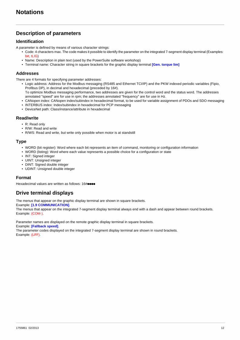
Description of parametersIdentificationA parameter is defined by means of various character strings:
• Code: 4 characters max. The code makes it possible to identify the parameter on the integrated 7-segment display terminal (Examples: brt, tLIG)
• Name: Description in plain text (used by the PowerSuite software workshop)• Terminal name: Character string in square brackets for the graphic display terminal [Gen. torque lim]
AddressesThere are 4 formats for specifying parameter addresses:
• Logic address: Address for the Modbus messaging (RS485 and Ethernet TCI/IP) and the PKW indexed periodic variables (Fipio, Profibus DP), in decimal and hexadecimal (preceded by 16#).To optimize Modbus messaging performance, two addresses are given for the control word and the status word. The addresses annotated "speed" are for use in rpm; the addresses annotated "frequency" are for use in Hz.
• CANopen index: CANopen index/subindex in hexadecimal format, to be used for variable assignment of PDOs and SDO messaging• INTERBUS index: Index/subindex in hexadecimal for PCP messaging• DeviceNet path: Class/instance/attribute in hexadecimal
Read/write• R: Read only• R/W: Read and write• R/WS: Read and write, but write only possible when motor is at standstill
Type• WORD (bit register): Word where each bit represents an item of command, monitoring or configuration information• WORD (listing): Word where each value represents a possible choice for a configuration or state• INT: Signed integer• UINT: Unsigned integer• DINT: Signed double integer• UDINT: Unsigned double integer
FormatHexadecimal values are written as follows: 16#pppp
Drive terminal displaysThe menus that appear on the graphic display terminal are shown in square brackets.Example: [1.9 COMMUNICATION].The menus that appear on the integrated 7-segment display terminal always end with a dash and appear between round brackets.Example: (COM-).
Parameter names are displayed on the remote graphic display terminal in square brackets.Example: [Fallback speed].The parameter codes displayed on the integrated 7-segment display terminal are shown in round brackets.Example: (LFF).

Profiles
What is a profile?There are three types of profile:
• Communication profiles• Functional profiles• Application profiles
Communication profilesA communication profile describes the characteristics of the bus or network:
• Cables• Connectors• Electrical characteristics• Access protocol• Addressing system• Periodic exchange service• Messaging service• ...
A communication profile is unique to a type of network (Fipio, Profibus DP, etc.) and is used by various different types of device.
Functional profilesA functional profile describes the behavior of a type of device. It defines:
• Functions• Parameters (name, format, unit, type, etc.)• Periodic I/O variables• State chart(s)• ...
A functional profile is common to all members of a device family (variable speed drives, encoders, I/O modules, displays, etc.).Ideally, functional profiles should be network-independent, but in reality they are not. They can feature common or similar parts. Thestandardized (IEC 61800-7) functional profiles of variable speed drives are:
• CiA402• PROFIDRIVE• CIP
DRIVECOM has been available since 1991.CiA402 "Device profile for drives and motion control" represents the next stage of this standard’s development and is maintained byCan In Automation.Some protocols also support the ODVA (Open DeviceNet Vendor Association) profile.
Application profilesApplication profiles define in their entirety the services to be provided by the devices on a machine. For example, "CiA DSP 417-2 V 1.01part 2: CANopen application profile for lift control systems - virtual device definitions".
InterchangeabilityThe aim of communication and functional profiles is to achieve interchangeability of the devices connected via the network.Although this aim is not always achieved, the profiles facilitate free competition.
13 1755861 02/2013

Profiles
Functional profiles supported by the Altivar 71I/O profileUsing the I/O profile simplifies PLC programming.
When controlling via the terminals or the display terminal, the I/O profile is used without knowing it.With an Altivar 71, the I/O profile can also be used when controlling via a network.
The drive starts up as soon as the run command is sent.The 16 bits of the control word can be assigned to a function or a terminal input.
This profile can be developed for simultaneous control of the drive via:• The terminals• The Modbus control word• The CANopen control word• The network card control word• The "Controller Inside" control word
The I/O profile is supported by the drive itself and therefore in turn by all the communication ports (integrated Modbus, CANopen and theEthernet, Fipio, ModbusPlus, Modbus, Uni-Telway, Profibus DP, DeviceNet, and INTERBUS communication cards).
CiA402 profileThe drive only starts up following a command sequence.The control word is standardized.5 bits of the control word (bits 11 to 15) can be assigned to a function or a terminal input.
The CiA402 profile is supported by the drive itself and therefore in turn by all the communication ports (integrated Modbus, CANopen andthe Ethernet, Fipio, ModbusPlus, Modbus, Uni-Telway, Profibus DP, DeviceNet, and INTERBUS communication cards).
The Altivar 71 supports the CiA402 profile’s "Velocity mode".
In the CiA402 profile, there are two modes that are specific to the Altivar 71 and characterize command and reference management (seesection “Command/reference switching”, page 37):
• Separate mode [Separate] (SEP)• Not separate mode [Not separ.] (SIM)
ODVA profileThe drive starts up as soon as the run command is sent.The control word is standardized.
The ODVA profile is supported by the DeviceNet communication card.
14 1755861 02/2013
I/O profile
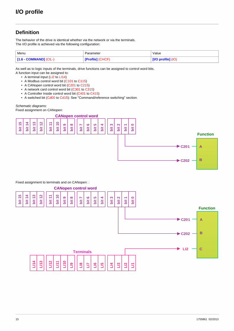
DefinitionThe behavior of the drive is identical whether via the network or via the terminals.The I/O profile is achieved via the following configuration:
As well as to logic inputs of the terminals, drive functions can be assigned to control word bits.A function input can be assigned to:
• A terminal input (LI2 to LI14)• A Modbus control word bit (C101 to C115)• A CANopen control word bit (C201 to C215)• A network card control word bit (C301 to C315)• A Controller Inside control word bit (C401 to C415)• A switched bit (Cd00 to Cd15): See "Command/reference switching" section.
Schematic diagrams:Fixed assignment on CANopen:
Fixed assignment to terminals and on CANopen: :
Menu Parameter Value
[1.6 - COMMAND] (CtL-) [Profile] (CHCF) [I/O profile] (IO)
C201
C202
bit 9
bit 8
bit 7
bit 6
bit 5
bit 4
bit 3
bit 2
bit 1
bit 0
bit 2
bit 1
bit 0
bit 1
1
bit 1
0
bit 1
3
bit 1
2
bit 1
5
bit 1
4
A
B
CANopen control word
Function
C201
C202
bit 9
bit 8
bit 7
bit 6
bit 5
bit 4
bit 3
bit 2
bit 1
bit 0
bit 2
bit 1
bit 0
bit 1
1
bit 1
0
bit 1
3
bit 1
2
bit 1
5
bit 1
4
A
B
LI2
LI10
LI9
LI8
LI7
LI6
LI5
LI4
LI3
LI2
LI1
LI12
LI11
LI14
LI13
C
CANopen control word
Terminals
Function
15 1755861 02/2013

I/O profile
Fixed assignment to terminals, on CANopen and on "Controller Inside" card:
Fixed assignment to terminals and on CANopen with command switching :
C201
C202
C401
bit 9
bit 8
bit 7
bit 6
bit 5
bit 4
bit 3
bit 2
bit 1
bit 0
bit 2
bit 1
bit 0
bit 1
1
bit 1
0
bit 1
3
bit 1
2
bit 1
5
bit 1
4
bit 9
bit 8
bit 7
bit 6
bit 5
bit 4
bit 3
bit 2
bit 1
bit 0
bit 2
bit 1
bit 0
bit 1
1
bit 1
0
bit 1
3
bit 1
2
bit 1
5
bit 1
4
A
B
LI2
LI10
LI9
LI8
LI7
LI6
LI5
LI4
LI3
LI2
LI1
LI12
LI11
LI14
LI13
C
Stop
CANopen control word
Terminals
Function
"Controller Inside" control word
Fast stop
C201
Cd02
LI5
LI10
LI9
LI8
LI7
LI6
LI5
LI4
LI3
LI2
LI1
LI12
LI11
LI14
LI13
bit 9
bit 8
bit 7
bit 6
bit 5
bit 4
bit 3
bit 2
bit 1
bit 0
bit 2
bit 1
bit 0
bit 1
1
bit 1
0
bit 1
3
bit 1
2
bit 1
5
bit 1
4
LI2
A
B
C
CANopen control word
Terminals
Function
CANopen
Terminals
Command switching
CCS
16 1755861 02/2013

I/O profile
Control word - run on state [2 wire] (2C)Please refer to the [1.5 INPUTS / OUTPUTS CFG] (I-O-) section of the Programming Manual.
The forward run command is automatically assigned to input LI1 and to bit 0 of the various control words.This assignment cannot be modified.The run command is active on state 1:
• Of input LI1, if the terminals are active• Of bit 0 of the control word, if the network is active
Bits 1 to 15 of the control words can be assigned to drive functions.
In the case of a [2 wire] (2C) run on state command and I/O profile, fixed assignment of a function input is possible using the followingcodes:
For example, to assign the operating direction command to bit 1 of CANopen, simply configure the [Reverse assign.] (rrS) parameter withthe value [C201] (C201).
bit 7 bit 6 bit 5 bit 4 bit 3 bit 2 bit 1 bit 0
Configurable Configurable Configurable Configurable Configurable Configurable Configurable Forward
bit 15 bit 14 bit 13 bit 12 bit 11 bit 10 bit 9 bit 8
Configurable Configurable Configurable Configurable Configurable Configurable Configurable Configurable
BitFixed assignments
Drive terminals Logic I/O card Extended I/O card Modbus CANopen Network card "Controller Inside"
card
bit 0 Forward
bit 1 LI2 - - C101 C201 C301 C401
bit 2 LI3 - - C102 C202 C302 C402
bit 3 LI4 - - C103 C203 C303 C403
bit 4 LI5 - - C104 C204 C304 C404
bit 5 LI6 - - C105 C205 C305 C405
bit 6 - LI7 - C106 C206 C306 C406
bit 7 - LI8 - C107 C207 C307 C407
bit 8 - LI9 - C108 C208 C308 C408
bit 9 - LI10 - C109 C209 C309 C409
bit 10 - - LI11 C110 C210 C310 C410
bit 11 - - LI12 C111 C211 C311 C411
bit 12 - - LI13 C112 C212 C312 C412
bit 13 - - LI14 C113 C213 C313 C413
bit 14 - - - C114 C214 C314 C414
bit 15 - - - C115 C215 C315 C415
1755861 02/2013 17

I/O profile
Control word - run on edge [3 wire] (3C)Please refer to the [1.5 INPUTS / OUTPUTS CFG] (I-O-) section of the Programming Manual.
The stop command is automatically assigned to input LI1 and to bit 0 of the control words.This assignment cannot be modified.This command enables running on state 1:
• Of input LI1, if the terminals are active• Of bit 0 of the control word, if the network is active
The forward run command is automatically assigned to input LI2 and to bit 1 of the control words.This assignment cannot be modified.The forward run command is active if the stop command is at 1 and on a rising edge (0 V 1):
• Of input LI2, if the terminals are active• Of bit 1 of the control word, if the network is active
Bits 2 to 15 of the control words can be assigned to drive functions.
In the case of a [3 wire] (3C) run on state command and I/O profile, fixed assignment of a function input is possible using the followingcodes:
For example, to assign the operating direction command to bit 2 of CANopen, simply configure the [Reverse assign.] (rrS) parameter withthe value [C202] (C202).
bit 7 bit 6 bit 5 bit 4 bit 3 bit 2 bit 1 bit 0
Configurable Configurable Configurable Configurable Configurable Configurable Forward Stop
bit 15 bit 14 bit 13 bit 12 bit 11 bit 10 bit 9 bit 8
Configurable Configurable Configurable Configurable Configurable Configurable Configurable Configurable
BitFixed assignments
Drive terminals Logic I/O card ExtendedI/O card Modbus CANopen Network card "Controller Inside"
card
bit 0 Authorization to run (Stop)
bit 1 Forward
bit 2 LI3 - - C102 C202 C302 C402
bit 3 LI4 - - C103 C203 C303 C403
bit 4 LI5 - - C104 C204 C304 C404
bit 5 LI6 - - C105 C205 C305 C405
bit 6 - LI7 - C106 C206 C306 C406
bit 7 - LI8 - C107 C207 C307 C407
bit 8 - LI9 - C108 C208 C308 C408
bit 9 - LI10 - C109 C209 C309 C409
bit 10 - - LI11 C110 C210 C310 C410
bit 11 - - LI12 C111 C211 C311 C411
bit 12 - - LI13 C112 C212 C312 C412
bit 13 - - LI14 C113 C213 C313 C413
bit 14 - - - C114 C214 C314 C414
bit 15 - - - C115 C215 C315 C415
18 1755861 02/2013

I/O profile
Status word (ETA)
The status word is identical in the I/O profile and the CiA402 profile. For more information, see section “CiA402 profile”, page 21.
bit 7 bit 6 bit 5 bit 4 bit 3 bit 2 bit 1 bit 0
Alarm Reserved(= 0 or 1) Reserved (=1)
Power section line supply
presentFault Running Ready Reserved
(= 0 or 1)
bit 15 bit 14 bit 13 bit 12 bit 11 bit 10 bit 9 bit 8
Direction of rotation
Stop via STOP key Reserved (=0) Reserved (=0) Reference
outside limitsReference reached
Command or reference via
networkReserved (=0)
1755861 02/2013 19

I/O profile
Example: I/O profile with positioning by sensors functionPlease refer to the [1.7 APPLICATION FUNCT.] (FUn-) section of the Programming Manual, under "Positioning by sensors".
In this example, a PLC is used to control the transfer of parts on a conveyor composed of transfer tables. Each table is controlled by avariable speed drive. The PLC and the drives are connected via a CANopen network.
The PLC controls the operation of the installation via the CANopen bus.
The drive uses the stop sensor to inhibit transfer of the part if the next table is unavailable. In this case, the PLC enables the sensors.If the next table is free, the drive transfers the part without stopping. In this case, the PLC disables the sensors.
The stop sensor is directly connected to the drive terminals.The slowdown sensor, which is also directly connected (to the drive) enables a more precise stop.
Configuration schematic diagram:
tEr
LCC
CAn
Mdb
nEt
APP
tEr
LCC
CAn
Mdb
nEt
APP
bit 9
bit 8
bit 7
bit 6
bit 5
bit 4
bit 3
bit 2
bit 1
bit 0
bit 2
bit 1
bit 0
C201
LI4
LI6
LI5
LI8
LI10
LI9
LI8
LI7
LI6
LI5
LI4
LI3
LI2
LI1
LI12
LI11
bit 1
1
bit 1
0
bit 1
3
bit 1
2
bit 1
5
bit 1
4
LI14
LI13
CANopen control word
Terminals
Command channel 1Cd1
Forward
Positioningby sensors
Reverse
Disabling of sensors
Forward stop sensor
Reverse stop sensor
Forward slowdown sensor
Reverse slowdown sensor
20 1755861 02/2013

I/O profile
Configure the following parameters:
Configuration via the remote graphic display terminal:
Note: On a [2 wire] (2C) state command, the forward command is automatically assigned to bit 0 of the CANopen control word.
Parameter Value Comment
Type of command On state (2 wire) The run command is obtained via bit 0 of the CANopen control word.Profile I/O profile
Reference 1 configuration CANopen The reference comes from the CANopen card.
Command 1 configuration CANopen The command comes from the CANopen card.
Assignment of stop sensor Input LI4
Assignment of slowdown sensor Input LI5
Assignment of sensor disable command Bit 1 of CANopen control word
Menu Parameter Value
[1.5 INPUTS / OUTPUTS CFG] (I-O-) [2/3 wire control] (tCC) [2 wire] (2C)
[1.6 - COMMAND] (CtL-) [Profile] (CHCF) [I/O profile] (IO)
[Ref. 1 channel] (Fr1) [CANopen] (CAn)
[Cmd channel 1] (Cd1) [CANopen] (CAn)
[1.7 APPLICATION FUNCT.] (FUn-)[POSITIONING BY SENSORS] (LPO-)
[Stop FW limit sw.] (SAF) [LI4] (LI4)
[Slowdown forward] (dAF) [LI5] (LI5)
[Disable limit sw.] (CLS) [C201] (C201)
1755861 02/2013 21

CiA402 profile
Functional descriptionb Drive operation involves two main functions, which are illustrated in the two diagrams below (the values in brackets are the CANopen
addresses of the parameters):
• Control diagram:
• Simplified diagram of speed control in "Velocity" mode:
b The main parameters are shown with their CiA402 name and their CiA402/Drivecom index (the values in brackets are the parametercodes).
These diagrams translate as follows for the Altivar system:
• Control diagram:
• Simplified diagram of speed regulation in "Velocity" mode:
Controlword(6040)
Statusword(6041)
Statemachine
M3
vl_target_velocity(6042)
vl_velocity_demand(6043)
Limit RampPower device
vl_velocity_acceleration (6048)vl_velocity_acceleration (6049)
vl_velocity_min_max amount (6046)
vl_control_effort(6044)
Control word(CMD)
Status word(ETA)
State machine
M3
Speed reference(LFRD)
Speed referenceafter ramp(FRHD)
Reference limit RampPower
module
Acceleration delta speed (SPAL)Acceleration delta time (SPAT)Deceleration delta speed (SPDL)Deceleration delta time (SPDT)
Velocity min amount (SMIL)Velocity max amount (SMAL)
Output speed(RFRD)
1755861 02/2013 22

CiA402 profile
CiA402 state chart
FaultPower section line supply present or absent
Power section line supply present
Transition conditionwith example of command
Value ofstatus word
Powerabsent
Powerpresent
Status display ongraphic display terminal
StateKey:
Examples:ETA=16#0637: Stop or forward, speed reachedETA=16#8637: Stop or reverse, speed reachedETA=16#0237: Forward, accelerating or deceleratingETA=16#8237: Reverse, accelerating or decelerating
Enableoperation
CMD=16#xxxF
Switched on
Ready to switch on
or
Switched on
Operation enabled
Power absentor present
Enableoperation
CMD=16#xxxF
DisableoperationCMD=16#0007orfast stop
Quick stopCMD=16#0002 Quick stop active
Switch onCMD=16#xxxF
ShutdownCMD=16#0006
Switch onCMD=16#0007
ShutdownCMD=16#0006
DisablevoltageCMD=16#0000orQuick stopCMD=16#0002 orSTOP keyorfreewheel stopat the terminalsormodificationof a configurationparameter
If Quick stop option code = 2: transition after stop.If Quick stop option code = 6:
Disable voltageCMD=16#0000orSTOP keyorfreewheel stop atterminals
DisablevoltageCMD=16#0000orQuick stopCMD=16#0002 orSTOP key
ShutdownCMD=16#0006
Disable voltageCMD=16#0000orSTOP keyorfreewheel stop at the terminalsorPower Removal
or
Switch on disabled
Fault disappeared and faults resetCMD=16#0080
Not ready to switch on
Entry intostate chart
Fault reaction active
From all states
Fault
Fault
1755861 02/2013 23

CiA402 profile
Description of statesEach state represents an internal reaction by the drive.This chart will change depending on whether the control word is sent (CMD) or an event occurs (a fault, for example).The drive state can be identified by the value of the status word (ETA).
1 - Not ready to switch onInitialization starts. This is a transient state invisible to the communication network.
2 - Switch on disabledThe drive is inactive.The drive is locked, no power is supplied to the motor.For a separate control section, it is not necessary to supply AC power to the power section.For a separate control section with line contactor, the contactor is not controlled.
The configuration and adjustment parameters can be modified.
3 - Ready to switch onAwaiting power section line supply.For a separate control section, it is not necessary to supply AC power to the power section, but the system will expect it in order to changeto state "4 - Switched on".For a separate control section with line contactor, the contactor is not controlled.
The drive is locked, no power is supplied to the motor.
The configuration and adjustment parameters can be modified.
4 - Switched onThe drive is supplied with AC power but is stationary.For a separate control section, the power section line supply must be present.For a separate control section with line contactor, the contactor is controlled.
The drive is locked, no power is supplied to the motor.The power stage of the drive is ready to operate, but voltage has not yet been applied to the output.
The adjustment parameters can be modified.Modification of a configuration parameter returns the drive to state "2 - Switch on disabled".
5 - Operation enabledThe drive is running.For a separate control section, the power section line supply must be present.For a separate control section with line contactor, the contactor is controlled.
The drive is unlocked, power is supplied to the motor.The drive functions are activated and voltage is applied to the motor terminals.However, in the case of an open-loop drive, if the reference is zero or the "Halt" command is applied, no power is supplied to the motor andno torque is applied.Auto-tuning (tUn) requires an injection of current into the motor. The drive must therefore be in state "5 - Operation enabled" for thiscommand.
The adjustment parameters can be modified.The configuration parameters cannot be modified.
Note: The command "4 - Enable operation" must be taken into consideration only if the channel is valid (see Communication monitoringpage 57). In particular, if the channel is involved in the command and the reference, transition 4 will take place only after thereference has been received for the first time.
The reaction of the drive to a "Disable operation" command depends on the value of the "Disable operation option code" (DOTD) parameter:• If the "Disable operation option code" parameter has the value 0, the drive changes to "4 - Switched on" and stops in freewheel stop.• If the "Disable operation option code" parameter has the value 1, the drive stops on ramp and then changes to "4 - Switched on".
24 1755861 02/2013

CiA402 profile
6 - Quick stop activeEmergency stop
The drive performs a fast stop, after which restarting will only be possible once the drive has changed to the "Switch on disabled" state.During fast stop, the drive is unlocked and power is supplied to the motor.The configuration parameters cannot be modified.
The condition for transition 12 to state "2 - Switch on disabled" depends on the value of the parameter "Quick stop option code" (QSTD):• If the "Quick stop option code" parameter has the value 2, the drive stops according to the fast stop ramp and then changes to state
"2 - Switch on disabled".• If the "Quick stop option code" parameter has the value 6, the drive stops according to the fast stop ramp and then remains in state
"6 - Quick stop active" until:- A "Disable voltage" command is received- Or the STOP key is pressed- Or there is a freewheel stop command via the terminals
7 - Fault reaction activeTransient state during which the drive performs an action appropriate to the type of fault.
The drive function is activated or deactivated according to the type of reaction configured in the fault management parameters.
8 - FaultDrive faulty.
The drive is locked, no power is supplied to the motor.
Summary
State Power section line supply for separate control section Power supplied to motor Modification of configuration
parameters
1 - Not ready to switch on Not required No Yes
2 - Switch on disabled Not required No Yes
3 - Ready to switch on Not required No Yes
4 - Switched on Required No Yes, return to "2 - Switch on disabled" state
5 - Operation enabled Required
Yes, apart from an open-loop drive with a zero reference or in the event of a "Halt" command
for an open-loop drive.
No
6 - Quick stop active Required Yes, during fast stop No
7 - Fault reaction active Depends on fault management configuration
Depends on fault management configuration -
8 - Fault Not required No Yes
1755861 02/2013 25

CiA402 profile
Control word (CMD)
x: Value is of no significance for this command.
0 V 1: Command on rising edge.
bit 7 bit 6 bit 5 bit 4 bit 3 bit 2 bit 1 bit 0
Fault reset
Reserved (=0) Reserved (=0) Reserved (=0)
Enable operation Quick stop Enable voltage Switch on
Ack. fault Run command Emergency stop
Authorization to supply AC
power
Contactor control
bit 15 bit 14 bit 13 bit 12 bit 11 bit 10 bit 9 bit 8
Assignable Assignable Assignable Assignable
By default, direction of
rotation command.
Reserved (=0) Reserved (=0)Halt
Halt
Command Transition address Final state
bit 7 bit 3 bit 2 bit 1 bit 0Example valueFault
resetEnable
operationQuick stop
Enable voltage Switch on
Shutdown 2, 6, 8 3 - Ready to switch on x x 1 1 0 16#0006
Switch on 3 4 - Switched on x x 1 1 1 16#0007
Enable operation 4 5 - Operation
enabled x 1 1 1 1 16#000F
Disable operation 5 4 - Switched on x 0 1 1 1 16#0007
Disable voltage 7, 9, 10, 12 2 - Switch on disabled x x x 0 x 16#0000
Quick stop11 6 - Quick stop
activex x 0 1 x 16#0002
7, 10 2 - Switch on disabled
Fault reset 15 2 - Switch on disabled 0 V 1 x x x x 16#0080
26 1755861 02/2013

CiA402 profile
Stop commands:The "Halt" command enables movement to be interrupted without having to leave the "5 - Operation enabled" state. The stop is performedin accordance with the [Type of stop] (Stt) parameter.
In the case of an open-loop drive, if the "Halt" command is active, no power is supplied to the motor and no torque is applied.In the case of a closed-loop drive, if the "Halt" command is active, power continues to be supplied to the motor and torque is applied duringstopping.
Regardless of the assignment of the [Type of stop] (Stt) parameter ([Fast stop] (FSt), [Ramp stop] (rMP), [Freewheel] (nSt), or [DCinjection] (dCI)), the drive remains in the "5 - Operation enabled" state.
A Fast Stop command at the terminals or using a bit of the control word assigned to Fast Stop causes a change to the "4 - Switched on"state. A "Halt" command does not cause this transition.A Freewheel Stop command at the terminals or using a bit of the control word assigned to Freewheel Stop causes a change to the "2 -Switch on disabled" state.
Assigning control word bitsIn the CiA402 profile, fixed assignment of a function input is possible using the following codes:
For example, to assign the DC injection braking to bit 13 of CANopen, simply configure the [DC injection assign.] (dCI) parameter withthe [C213] (C213) value.
Bit 11 is assigned by default to the operating direction command [Reverse assign.] (rrS).
WARNINGRISK OF EQUIPMENT DAMAGEWhen the braking loop is configured, it is necessary to use the "Halt" command (bit 8 of CMD command word) to stop.
Failure to follow these instructions can result in death, serious injury or equipment damage.
Bit Integrated Modbus CANopen Network card "Controller Inside" card
bit 11 C111 C211 C311 C411
bit 12 C112 C212 C312 C412
bit 13 C113 C213 C313 C413
bit 14 C114 C214 C314 C414
bit 15 C115 C215 C315 C415
1755861 02/2013 27

CiA402 profile
Status word (ETA)
x: In this state, the value of the bit can be 0 or 1.
(1) This mask can be used by the PLC program to test the chart state.
(2) Fault following state "6 - Quick stop active".
bit 7 bit 6 bit 5 bit 4 bit 3 bit 2 bit 1 bit 0
Warning Switch on disabled Quick stop Voltage
enabled Fault Operation enabled Switched on Ready to
switch on
AlarmPower section
line supply disabled
Emergency stop
Power section line supply
presentFault Running Ready
Awaiting power section
line supply
bit 15 bit 14 bit 13 bit 12 bit 11 bit 10 bit 9 bit 8
Direction of rotation
Stop via STOP key Reserved (=0) Reserved (=0)
Internal limit active
Target reached Remote
Reserved (=0)Reference
outside limitsReference reached
Command or reference via
network
Statusbit 6 bit 5 bit 4 bit 3 bit 2 bit 1 bit 0 ETA
masked by 16#006F (1)
Switch on disabled
Quick stop
Voltage enabled Fault Operation
enabledSwitched
onReady to switch on
1 - Not ready to switch on 0 x x 0 0 0 0 -
2 - Switch on disabled 1 x x 0 0 0 0 16#0040
3 - Ready to switch on 0 1 x 0 0 0 1 16#0021
4 - Switched on 0 1 1 0 0 1 1 16#0023
5 - Operation enabled 0 1 1 0 1 1 1 16#0027
6 - Quick stop active 0 0 1 0 1 1 1 16#0007
7 - Fault reaction active 0 x x 1 1 1 1 -
8 - Fault 0 x x 1 0 0 0 16#0008 (2)
or 16#0028
28 1755861 02/2013

CiA402 profile
Starting sequenceThe command sequence in the state chart depends on how power is being supplied to the drive.There are three possible scenarios:
(1) The power section supplies the control section.
M MM M
Power section line supply
Pow
er s
ectio
nlin
e su
pply
Control section power supply
Direct
Not separate (1)
Direct
Separate
Line contactor controlled by the drive
Separate
DRIVE DRIVE DRIVE
Pow
er s
ectio
nlin
e su
pply
Pow
er s
ectio
nlin
e su
pply
Con
trol s
ectio
npo
wer
sup
ply
Con
trol s
ectio
npo
wer
sup
ply
1755861 02/2013 29

CiA402 profile
Sequence for a drive powered by the power section line supplyBoth the power and control sections are powered by the power section line supply.If power is supplied to the control section, it has to be supplied to the power section as well.The following sequence must be applied:
b Step 1• Send the "2 - Shutdown" command
M
2
3
4 5
6
7
1
11
9
8
12
10
15
14
13
0
1
2
3
4
5 6
8
7
Pow
er s
ectio
nlin
e su
pply
Bus
or n
etw
ork
DRIVE
Not ready to switch on
Entry into state chart
Switch ondisabled
Ready toswitch on
Switched on
Operationenabled
Quick stopactive
Fault
Fault reactionactive
From all states
Shutdown Disable voltageor Quick stop
Shutdown
Disableoperation
Disablevoltage
Enableoperation
Shutdown
Switch on
Disable voltageor Quick stop
Quick stop
30 1755861 02/2013

CiA402 profile
b Step 2• Check that the drive is in the "3 - Ready to switch on" state.• Then send the "4 - Enable operation" command.• The motor can be controlled (send a reference not equal to zero).
Note: It is possible, but not necessary, to send the "3 - Switch on" command followed by the "4 - Enable Operation" command to switchsuccessively into the states "3 - Ready to Switch on", "4 - Switched on" and then "5 - Operation Enabled".The "4 - Enable operation" command is sufficient.
M
2
3
5
6
7
1
11
9
8
12
10
15
14
13
0
1
2
3
4
5 6
8
7
4
Not ready toswitch on
Entry into state chart
Switch ondisabled
Ready toswitch on
Switched on
Operationenabled
Quick stopactive
Fault
Fault reaction active
From all states
Switch on Disable voltageor Quick stop
Shutdown
Disableoperation
Disablevoltage
Enableoperation
Shutdown
Switch on
Disable voltageor Quick stop
Quick stop
Pow
er s
ectio
nlin
e su
pply
Bus
or n
etw
ork
DRIVE
1755861 02/2013 31

CiA402 profile
Sequence for a drive with separate control sectionPower is supplied separately to the power and control sections.If power is supplied to the control section, it does not have to be supplied to the power section as well.The following sequence must be applied:
b Step 1• The power section line supply is not necessarily present.• Send the "2 - Shutdown" command
M
2
3
4 5
6
7
1
11
9
8
12
10
15
14
13
0
1
2
3
4
5 6
8
7
Pow
er s
ectio
nlin
e su
pply
Bus
or n
etw
ork
DRIVE
Con
trol
sec
tion
pow
er s
uppl
y
Not ready toswitch on
Entry into state chart
Switch ondisabled
Ready toswitch on
Switched on
Operationenabled
Quick stopactive
Fault
Fault reactionactive
Shutdown Disable voltageor Quick stop
Shutdown
Disableoperation
Disablevoltage
Enableoperation
Shutdown
Switch on
Disable voltageor Quick stop
Quick stop
From all states
32 1755861 02/2013

CiA402 profile
b Step 2• Check that the drive is in the "3 - Ready to switch on" state.• Check that the power section line supply is present ("Voltage enabled" of the status word).
• Send the "3 - Switch on" command
Power section line supply Terminal display Status word
Absent nLP 16#pp21
Present rdY 16#pp31
M
2
3
4 5
6
7
1
11
9
8
12
10
15
14
13
0
1
2
3
4
5 6
8
7
Pow
er s
ectio
nlin
e su
pply
Bus
or n
etw
ork
DRIVE
Con
trol
sec
tion
pow
er s
uppl
y
Not ready toswitch on
Entry into state chart
Switch ondisabled
Ready toswitch on
Switched on
Operationenabled
Quick stopactive
Fault
Fault reactionactive
From all states
Shutdown Disable voltageor Quick stop
Shutdown
Disableoperation
Disablevoltage
Enableoperation
Shutdown
Switch on
Disable voltageor Quick stop
Quick stop
1755861 02/2013 33

CiA402 profile
b Step 3• Check that the drive is in the "4 - Switched on" state.• Then send the "4 - Enable operation" command.• The motor can be controlled (send a reference not equal to zero).• If the power section line supply is still not present in the "4 - Switched on" state after a time delay [Mains V. time out] (LCt), the drive
will switch to fault mode (LCF).
M
2
3
4 5
6
7
1
11
9
8
12
10
15
14
13
0
1
2
3
4
5 6
8
7
Pow
er s
ectio
nlin
e su
pply
Bus
or n
etw
ork
DRIVE
Con
trol
sec
tion
pow
er s
uppl
y
Not ready toswitch on
Entry into state chart
Switch ondisabled
Ready toswitch on
Switched on
Operationenabled
Quick stopactive
Fault
Fault reactionactive
From all states
Shutdown Disable voltageor Quick stop
Shutdown
Disableoperation
Disablevoltage
Enableoperation
Shutdown
Switch on
Disable voltageor Quick stop
Quick stop
34 1755861 02/2013

CiA402 profile
Sequence for a drive with line contactor controlPower is supplied separately to the power and control sections.If power is supplied to the control section, it does not have to be supplied to the power section as well. The drive controls the line contactor.The following sequence must be applied:
b Step 1• The power section line supply is not present as the line contactor is not being controlled.• Send the "2 - Shutdown" command
M
2
3
4 5
6
7
1
11
9
8
12
10
15
14
13
0
1
2
3
4
5 6
8
7
Pow
er s
ectio
nlin
e su
pply
Bus
or n
etw
ork
DRIVE
Con
trol
sec
tion
pow
er s
uppl
y
Not ready toswitch on
Entry into state chart
Switch ondisabled
Ready toswitch on
Switched on
Operationenabled
Quick stopactive
Fault
Fault reactionactive
Shutdown Disable voltageor Quick stop
Shutdown
Disableoperation
Disablevoltage
Enableoperation
Shutdown
Switch on
Disable voltageor Quick stop
Quick stop
From all states
1755861 02/2013 35

CiA402 profile
b Step 2• Check that the drive is in the "3 - Ready to switch on" state.• Send the "3 - Switch on" command, which will close the line contactor and switch on the power section line supply.
M
2
3
4 5
6
7
1
11
9
8
12
10
15
14
13
0
1
2
3
4
5 6
8
7
Pow
er s
ectio
nlin
e su
pply
Bus
or n
etw
ork
DRIVE
Con
trol
sec
tion
pow
er s
uppl
y
Not ready toswitch on
Entry into state chart
Switch ondisabled
Ready toswitch on
Switched on
Operationenabled
Quick stopactive
Fault
Fault reactionactive
From all states
Shutdown Disable voltageor Quick stop
Shutdown
Disableoperation
Disablevoltage
Enableoperation
Shutdown
Switch on
Disable voltageor Quick stop
Quick stop
36 1755861 02/2013

CiA402 profile
b Step 3• Check that the drive is in the "4 - Switched on" state.• Then send the "4 - Enable operation" command.• The motor can be controlled (send a reference not equal to zero).• If the power section line supply is still not present in the "4 - Switched on" state after a time delay [Mains V. time out] (LCt), the drive
will switch to fault mode (LCF).
M
2
3
4 5
6
7
1
11
9
8
12
10
15
14
13
0
1
2
3
4
5 6
8
7
Pow
er s
ectio
nin
e su
pply
Bus
or n
etw
ork
DRIVE
Con
trol
sec
tion
pow
er s
uppl
y
Not ready toswitch on
Entry into state chart
Switch ondisabled
Ready toswitch on
Switched on
Operationenabled
Quick stopactive
Fault
Fault reactionactive
From all states
Shutdown Disable voltageor Quick stop
Shutdown
Disableoperation
Disablevoltage
Enableoperation
Shutdown
Switch on
Disable voltageor Quick stop
Quick stop
1755861 02/2013 37
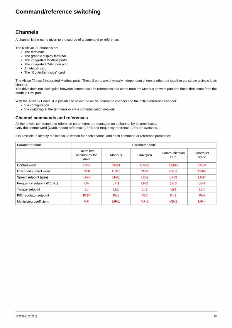
Command/reference switching
ChannelsA channel is the name given to the source of a command or reference.
The 6 Altivar 71 channels are:• The terminals• The graphic display terminal• The integrated Modbus ports• The integrated CANopen port• A network card• The "Controller Inside" card
The Altivar 71 has 2 integrated Modbus ports. These 2 ports are physically independent of one another but together constitute a single logicchannel.The drive does not distinguish between commands and references that come from the Modbus network port and those that come from theModbus HMI port.
With the Altivar 71 drive, it is possible to select the active command channel and the active reference channel:• Via configuration• Via switching at the terminals or via a communication network
Channel commands and referencesAll the drive’s command and reference parameters are managed on a channel-by-channel basis.Only the control word (CMd), speed reference (LFrd) and frequency reference (LFr) are switched.
It is possible to identify the last value written for each channel and each command or reference parameter:
Parameter name Parameter code
Taken into account by the
driveModbus CANopen Communication
cardController
inside
Control word CMd CMd1 CMd2 CMd3 CMd4
Extended control word CMI CMI1 CMI2 CMI3 CMI4
Speed setpoint (rpm) LFrd LFd1 LFd2 LFd3 LFd4
Frequency setpoint (0.1 Hz) LFr LFr1 LFr2 LFr3 LFr4
Torque setpoint Ltr Ltr1 Ltr2 Ltr3 Ltr4
PID regulator setpoint PISP PIr1 PIr2 PIr3 PIr4
Multiplying coefficient MFr MFr1 MFr2 MFr3 MFr4
1755861 02/2013 38

Command/reference switching
Not separate modeCommand and reference come from the same channel.
In CiA402 profile, not separate mode is configured via the terminal:
Separate modeCommand and reference may come from different channels.
In CiA402 profile, separate mode is achieved via configuration with the terminal:
In I/O profile, the drive is automatically in separate mode.
Menu Parameter Value
[1.6 - COMMAND] (CtL-) [Profile] (CHCF) [Not separ.] (SIM)
Menu Parameter Value
[1.6 - COMMAND] (CtL-) [Profile] (CHCF) [Separate] (SEP)
Menu Parameter Value
[1.6 - COMMAND] (CtL-) [Profile] (CHCF) [I/O profile] (IO)
-10V+10V
TER
MIN
ALS
Ref
eren
ceC
omm
and
Digital reference
TER
MIN
ALS
Ref
eren
ceC
omm
and
CA
Nop
en
CANopen
1755861 02/2013 39

Command/reference switching
Switching in not separate modeSwitching takes place between 2 channels simultaneously for both reference and command.
In this example, the command and reference come either from CANopen or from the terminals.
Switching in separate modeSwitching can take place between 2 channels independently for the reference and command.
In this example, the command always comes from the terminals; the reference can come either from CANopen or from the terminals.
-10V+10v
CANopen
CANopen
Control register
TER
MIN
ALS
Ref
eren
ceC
omm
and
Digital reference
TER
MIN
ALS
Ref
eren
ceC
omm
and
CANopen
CANopen
Digital reference
-10V+10V
40 1755861 02/2013

Command/reference switching
Channel switchingReference channel configurationReference channel configuration enables reference sources to be predefined, which can be modified or switched subsequently via acommand.
There are 3 predefined reference channels:• Reference channel 1• Reference channel 1B• Reference channel 2
Reference channels 1 and 1B are used for drive application functions.Reference channel 2 is connected directly to the reference limiting function, bypassing the application functions.
The predefined reference channels are assigned via the [Ref. 1 channel] (Fr1), [Ref. 1B channel] (Fr1b) and [Ref. 2 channel] (Fr2)configuration parameters, which can have the following values:
• [No] (nO): Not assigned• [AI1] (AI1): Analog input AI1• [AI2] (AI2): Analog input AI2• [AI3] (AI3): Analog input AI3 (if extension card present)• [AI4] (AI4): Analog input AI4 (if extension card inserted)• [HMI] (LCC): Graphic display terminal• [Modbus] (Mdb): Integrated Modbus• [CANopen] (CAn): Integrated CANopen• [Com. card] (nEt): Communication card (if inserted)• [C.Insid. card] (APP): Controller Inside card (if inserted)• [RP] (PI): Frequency input, (if card inserted)• [Encoder] (PG): Encoder input (if card inserted)
Note: The "+speed/-speed" function is on reference channel 2. See the Programming Manual for more information.
Command channel configurationCommand channel configuration enables command sources to be predefined, which can be modified or switched subsequently via acommand.
There are 2 predefined command channels:• Command channel 1• Command channel 2
The predefined command channels are assigned via the [Cmd channel 1] (Cd1) and [Cmd channel 2] (Cd2) configuration parameters,which can have the following values:
• [Terminals] (tEr): Terminals• [HMI] (LCC): Graphic display terminal• [Modbus] (Mdb): Integrated Modbus• [CANopen] (CAn): Integrated CANopen• [Com. card](nEt): Communication card (if inserted)• [C.Insid. card] (APP): Controller Inside card (if inserted)
1755861 02/2013 41

Command/reference switching
SwitchesA channel switch is used to select predefined channels.
It can be:• Defined via configuration• Actuated either by an input (terminals) or a control word bit (network)• Written via a network during operation (modification of a configuration parameter)
The possible switch values are:
The values Fr1, Fr1b, Fr2, Cd1 and Cd2 are either configured or written via the network during operation.
In I/O and CiA402 (separate mode) profiles, independent switching is possible:
In CiA402 profile (not separate mode) switching is simultaneous:
Function referenceswitching[Ref 1B switching] (rCb)
Direct reference switching[Ref. 2 switching] (rFC)
Command switching[Cmd switching] (CCS)
Channel 1 Fr1 Fr1 Cd1
Channel 1B Fr1b - -
Channel 2 - Fr2 Cd2
Drive input LI1 ... LI6
Logic I/O card input LI7 ... LI10
Extended I/O card input LI11 ... LI14
Modbus command bit bit 0 = C100 ... bit 15 = C115
CANopen command bit bit 0 = C200 ... bit 15 = C215
Network command bit bit 0 = C300 ... bit 15 = C315
Controller Inside command bit bit 0 = C400 ... bit 15 = C415
Type Channel 1 Channel 2 Switching
Reference
Function reference 1[Ref. 1 channel] (Fr1)
Function reference 1B[Ref. 1B channel] (Fr1b)
Function reference switching[Ref 1B switching] (rCb)
Function reference 1 or 1B[Ref. 1 channel] (Fr1)[Ref. 1B channel] (Fr1b)
Direct reference 2[Ref. 2 channel] (Fr2)
Direct reference switching[Ref. 2 switching] (rFC)
Command Command 1[Cmd channel 1] (Cd1)
Command 2[Cmd channel 2] (Cd2)
Command switching[Cmd switching] (CCS)
Type Channel 1 Channel 2 Switching
Reference and Command
Function reference 1 or 1B[Ref. 1 channel] (Fr1)[Ref. 1B channel] (Fr1b)
Direct reference 2[Ref. 2 channel] (Fr2) Direct reference switching
[Ref. 2 switching] (rFC)Command 1[Cmd channel 1] (Cd1)
Command 2[Cmd channel 2] (Cd2)
VV
VV
VV
VV
VV
42 1755861 02/2013

Command/reference switching
Reference switching principleA detailed description is given in the Programming Manual.
This diagram shows reference switching as applicable to all the following modes:• I/O profile• CiA402 profile and separate mode• CiA402 profile and not separate mode
rCb
rFC
Fr1Fr2LIppC1ppC2ppC3ppC4pp
Fr1Fr1bLIppC1ppC2ppC3ppC4pp
Fr1
CANopen
RØseau
AI1C
AI2C
LFr1
LFr2
LFr3
AI2
Modbus
AI1
TerminalLFr
ControllerLFr4
Fr1
AI1C
AI2C AI2
AI1
LFr
Fr1b
AI1C
AI2C
LFr1
LFr2
LFr3
AI1
AI2
LFr
LFr4
Fr2
AI1C
AI2C
LFr1
LFr2
LFr3
AI1
AI2
LFr
LFr4
Reference channel 1
Display terminal
Modbus
CANopen
Network
Controller
Reference channel 1B
Display terminal
Modbus
CANopen
Network
Controller
Reference channel 2
Display terminal
Modbus
CANopen
Network
Controller
Function reference switching
Application function output reference
Direct reference 2
Direct reference switching Reference
limit Ramp
Function
1755861 02/2013 43

Command/reference switching
Command switching principleA detailed description is given in the Programming Manual.
I/O profile or CiA402 profile (separate mode)
CiA402 profile (not separate mode)
(1) In not separate mode, command switching follows reference switching. It is therefore reference switching that switches the command.
CCS
Cd1Cd2LIppC1ppC2ppC3ppC4pp
Cd1
RUN/STOPFWD/REV
CANopen
RØseau
LIx
CMD1
CMD2
CMD3
Terminal
Modbus
ControllerCMD4
Cd2
RUN/STOPFWD/REV
LIx
CMD1
CMD2
CMD3
Terminal
ControllerCMD4
Bornier
Command channel 1
Command switching
Command channel 2
RunStopForwardReverse
Terminals
Display terminal
Modbus
CANopen
Network
Controller
Terminals
Display terminal
Modbus
CANopen
Network
Controller
rFC
Fr1
LIx AI1
AI2
RUN/STOPFWD/REV
CMD1
CMD2
CMD3
CMD4
LIx
Fr2
LIx
RUN/STOPFWD/REV
CMD1
CMD2
CMD3
CMD4
Fr1Fr2LIppC111 ... C115C211 ... C215C311 ... C315C411 ... C415
AI1
AI2
Reference channel 1 (1)
Direct reference switching (1)
Reference channel 2 (1)
RunStopForwardReverse
Display terminal
Modbus
CANopen
Network
Controller
Display terminal
Modbus
CANopen
Network
Controller
44 1755861 02/2013

Command/reference switching
Assigning control word bitsI/O profileThe I/O profile is extremely flexible in terms of assigning and switching the 16 control word bits.
To switch a control word bit using:• an input from the terminals• or a control word bit from another communication channel
simply configure a switched assignment for the function input (CDpp), instead of a fixed assignment (Cppp).
Inputs and bits of the same order are switched.Inputs LI1 to LI6 of the drive terminals can be used to switch control word bits 0 to 5.With a logic I/O card using inputs LI7 to LI10, control word bits 6 to 9 can also be switched.With an extended I/O card using inputs LI11 to LI14, control word bits 10 to 13 can also be switched.
ExampleFunction input A is always controlled by bit 1 of the CANopen control word.Function input B is always controlled by input LI5 on the terminals.Depending on the value of LI2, function input C is controlled:
• Either by input LI3 on the terminals• Or by bit 2 of the CANopen control word
Once a bit has been assigned to a switchable assignment, it can no longer be assigned to a fixed assignment, and vice versa.Example: Once a function input has been assigned to CD04, it cannot be assigned to LI5, C104, C204, C304 or C404.
C201
Cd02
LI5
LI10
LI9
LI8
LI7
LI6
LI5
LI4
LI3
LI2
LI1
LI12
LI11
LI14
LI13
bit 9
bit 8
bit 7
bit 6
bit 5
bit 4
bit 3
bit 2
bit 1
bit 0
bit 2
bit 1
bit 0
bit 1
1
bit 1
0
bit 1
3
bit 1
2
bit 1
5
bit 1
4
LI2
A
C
B
CANopen control word
Terminals
Function
CANopen
Terminals
Command switching
CCS
1755861 02/2013 45

Command/reference switching
The tables below show assignments on the basis of input or bit.
Run on state command [2 wire] (2C):In all macro configurations, bit 1 is assigned by default to the operating direction command [Reverse assign.] (rrS).
Run on edge command [3 wire] (3C):In all macro configurations, bit 2 is assigned by default to the operating direction command [Reverse assign.] (rrS).
Bit Switched assignment
Fixed assignments
Drive terminals Logic I/O card Extended
I/O cardIntegrated Modbus CANopen Network card "Controller
Inside" card
bit 0 Forward
bit 1 Cd01 LI2 - - C101 C201 C301 C401
bit 2 Cd02 LI3 - - C102 C202 C302 C402
bit 3 Cd03 LI4 - - C103 C203 C303 C403
bit 4 Cd04 LI5 - - C104 C204 C304 C404
bit 5 Cd05 LI6 - - C105 C205 C305 C405
bit 6 Cd06 - LI7 - C106 C206 C306 C406
bit 7 Cd07 - LI8 - C107 C207 C307 C407
bit 8 Cd08 - LI9 - C108 C208 C308 C408
bit 9 Cd09 - LI10 - C109 C209 C309 C409
bit 10 Cd10 - - LI11 C110 C210 C310 C410
bit 11 Cd11 - - LI12 C111 C211 C311 C411
bit 12 Cd12 - - LI13 C112 C212 C312 C412
bit 13 Cd13 - - LI14 C113 C213 C313 C413
bit 14 Cd14 - - - C114 C214 C314 C414
bit 15 Cd15 - - - C115 C215 C315 C415
Bit Switched assignment
Fixed assignments
Drive terminals Logic I/O card Extended
I/O cardIntegrated Modbus CANopen Network card "Controller
Inside" card
bit 0 Run authorization
bit 1 Forward
bit 2 Cd02 LI3 - - C102 C202 C302 C402
bit 3 Cd03 LI4 - - C103 C203 C303 C403
bit 4 Cd04 LI5 - - C104 C204 C304 C404
bit 5 Cd05 LI6 - - C105 C205 C305 C405
bit 6 Cd06 - LI7 - C106 C206 C306 C406
bit 7 Cd07 - LI8 - C107 C207 C307 C407
bit 8 Cd08 - LI9 - C108 C208 C308 C408
bit 9 Cd09 - LI10 - C109 C209 C309 C409
bit 10 Cd10 - - LI11 C110 C210 C310 C410
bit 11 Cd11 - - LI12 C111 C211 C311 C411
bit 12 Cd12 - - LI13 C112 C212 C312 C412
bit 13 Cd13 - - LI14 C113 C213 C313 C413
bit 14 Cd14 - - - C114 C214 C314 C414
bit 15 Cd15 - - - C115 C215 C315 C415
46 1755861 02/2013

Command/reference switching
CiA402 profile
Control word bits of the same order are switched if the function inputs are assigned to switchable bits.Switching may be possible using LI12, LI13 or LI14 on an extended I/O card.
The table below shows assignments on the basis of input or bit.
Once a bit has been assigned to a switchable assignment, it can no longer be assigned to a fixed assignment, and vice versa.Example: Once a function input has been assigned to Cd04, it cannot be assigned to LI5, C104, C204, C304 or C404.
Bit Switched assignment
Fixed assignments
Drive terminals Logic I/O card Extended I/O
cardIntegrated Modbus CANopen Network card "Controller
Inside" card
bit 0 - LI1 - - - - - -
bit 1 - LI2 - - - - - -
bit 2 - LI3 - - - - - -
bit 3 - LI4 - - - - - -
bit 4 - LI5 - - - - - -
bit 5 - LI6 - - - - - -
bit 6 - - LI7 - - - - -
bit 7 - - LI8 - - - - -
bit 8 - - LI9 - - - - -
bit 9 - - LI10 - - - - -
bit 10 - - - LI11 - - - -
bit 11 Cd11 - - LI12 C111 C211 C311 C411
bit 12 Cd12 - - LI13 C112 C212 C312 C412
bit 13 Cd13 - - LI14 C113 C213 C313 C413
bit 14 Cd14 - - - C114 C214 C314 C414
bit 15 Cd15 - - - C115 C215 C315 C415
1755861 02/2013 47

Command/reference switching
Example: I/O profile with positioning by sensors functionLet us return to the example given in the "I/O profile" section.
In the diagram below, the command comes from CANopen alone:
For a different application, provision must be made to enable the switching of the run commands and the disabling of the sensors and thereference at the terminals.The new diagram will look like this:
tEr
LCC
CAn
Mdb
nEt
APP
tEr
LCC
CAn
Mdb
nEt
APPbi
t 9
bit 8
bit 7
bit 6
bit 5
bit 4
bit 3
bit 2
bit 1
bit 0
bit 2
bit 1
bit 0
C201
LI4
LI6
LI5
LI8
LI10
LI9
LI8
LI7
LI6
LI5
LI4
LI3
LI2
LI1
LI12
LI11
bit 1
1
bit 1
0
bit 1
3
bit 1
2
bit 1
5
bit 1
4
LI14
LI13
CANopen control word
Terminals
Command channel 1Cd1
Forward
Positioningby sensors
Reverse
Disabling of sensors
Forward stop sensor
Reverse stop sensor
Forward slowdown sensor
Reverse slowdown sensor
tEr
LCC
CAn
Mdb
nEt
APP
bit 9
bit 8
bit 7
bit 6
bit 5
bit 4
bit 3
bit 2
bit 1
bit 0
bit 2
bit 1
bit 0
CD01
LI4
LI5
LI10
LI9
LI8
LI7
LI6
LI5
LI4
LI3
LI2
LI1
LI12
LI11
bit 1
1
bit 1
0
bit 1
3
bit 1
2
bit 1
5
bit 1
4
tEr
LCC
CAn
Mdb
nEt
APP
LI8LI8
LI14
LI13
CANopen control word
Terminals
Command channel 1Cd1
Forward
Positioningby sensors
Reverse
Disabling of sensors
Forward stop sensor
Reverse stop sensor
Forward slowdown sensor
Reverse slowdown sensor
Command switching
CCS
Command channel 2Cd2
48 1755861 02/2013

Command/reference switching
Configure the following parameters:
Configuration via the graphic display terminal:
Parameter Value Comment
Type of command On state (2 wire) The run command is obtained via bit 0 of the CANopen control word.
Profile IO profile
Reference 1 configuration CANopen Reference 1 comes from the CANopen card.
Command 1 configuration CANopen Command 1 comes from the CANopen card.
Reference 1B configuration AI1 Reference 1B comes from analog input 1. Reference 1B has to be taken rather than reference 2, as use is to be made of the positioning function.
Command 2 configuration Terminals Command 2 comes from the terminals.
Assignment of stop sensor Input LI4 The sensor inputs are not switched.
Assignment of slowdown sensor Input LI5
Assignment of sensor disable command
Bit 1 switched.
Assignment of command switch Input LI8 The LI8 inputs enable the command and reference to be switched.
Assignment of application reference switch 1/1B
Input LI8
Menu/submenu Parameter Value
[1.5 INPUTS / OUTPUTS CFG] (I-O-) [2/3 wire control] (tCC) [2 wire] (2C)
[1.6 - COMMAND] (CtL-) [Profile] (CHCF) [I/O profile] (IO)
[Ref. 1 channel] (Fr1) [CANopen] (CAn)
[Cmd channel 1] (Cd1) [CANopen] (CAn)
[Cmd channel 2] (Cd2) [Terminals] (tEr)
[Cmd switching] (CCS) [LI8] (LI8)
[1.7 APPLICATION FUNCT.] (FUn-)[POSITIONING BY SENSORS] (LPO-)
[Stop FW limit sw.] (SAF) [LI4] (LI4)
[Slowdown forward] (dAF) [LI5] (LI5)
[Disable limit sw.] (CLS) [Cd01] (Cd01)
[Ref. 1B channel] (Fr1b) [Ref. AI1] (AI1)
[Ref 1B switching] (rCb) [LI8] (LI8)
1755861 02/2013 49

Command/reference switching
Copy on switchingWhen switching channels, it is possible to copy the reference or command from function channel 1 to direct channel 2.
If a copy is not made, the drive stops according to the configured stop type [Type of stop] (Stt) until the first command and reference arereceived.
The reference before ramp (FrH) is copied unless the direct channel 2 reference is via +/- speed.If the direct channel 2 reference is via +/- speed, the after ramp (rFr) reference is copied.
If the direct channel 2 command is via the terminals, the function channel 1 command is not copied even in pulse control (3-wire) [3 wire](3C).
If the direct channel 2 reference is via AI1, AI2, AI3, AI4, the encoder input or frequency input, the function channel 1 reference is not copied.
Menu Submenu
[1.6 COMMAND] (CtL-)
Parameter Possible values
[Copy channel 1 --> 2] No copy.[No] (nO)Copy reference[Reference] (SP)Copy command[Command] (Cd)Copy command and reference[Cmd + ref.] (ALL)
50 1755861 02/2013

Forced local
DefinitionForced local mode supports switching to the terminals or display terminal.This function complements channel switching and makes it possible to make use of an existing function from the Altivar 58 range.
Forced local mode is only available in CiA402 profile, not in I/O profile.
All other communication takes priority over forced local mode.
Forced local mode can be configured via the display terminal:
In "forced local" state:• Any attempts to write the parameter via one of these channels is rejected (applies to command, reference and adjustment
parameters).• However, the parameters can be read.• The drive does not register a communication fault.
On exiting "forced local" mode:• The drive copies the run commands, the direction and the forced local reference to the active channel (maintained).• Monitoring of the active command and reference channels resumes following a time delay [Time-out forc. local] (FLOt).• Drive control only takes effect once the drive has received the reference and the command.
The time delay [Time-out forc. local] (FLOt) (default value = 10 s) can be configured via the remote graphic display terminal:
Menu Submenu
[1.9 COMMUNICATION] (COM-) [FORCED LOCAL] (LCF-)
Parameter Possible values
Forced local switch[Forced local assign.] (FLO)
Function inactive:[No] (nO)Assignment to a logic input LI1 ... LI14:[LI1] (LI1) ... [LI14] (LI14)Forced local mode is active when the input is at state 1.
Forced local channel[Forced local Ref.] (FLOC)
Forced local on stop[No] (nO)Assignment of the command to the terminals and of the reference to one of the analog inputs AI1 ... A14[AI2 ref.] (AI2), [AI3 ref.] (AI3), [AI4 ref.] (AI4)Assignment of the command to the terminals and of the reference to the frequency input (if card present)[Pulse Input] (PI)Assignment of the reference [HMI Frequency ref.] (LFr) and of the command(RUN/STOP/FWD/REV buttons) to the graphic display terminal[HMI] (LCC)
Menu Submenu Parameter
[1.9 COMMUNICATION] (COM-) [FORCED LOCAL] (LCF-) [Time-out forc. local] (FLOt)
51 1755861 02/2013

Forced local
Forced local mode and reference switchingA detailed description is given in the Programming Manual.
This diagram shows reference switching as applicable to the following modes:• CiA402 profile and separate mode• CiA402 profile and not separate mode
AI1C
AI2C
LFr1
LFr2
LFr3
AI2
AI1
LFr
LFr4
AI2
AI1
AI1C
AI2C
LFr1
LFr2
LFr3
AI1
AI2
LFr
LFr4
AI1C
AI2C
LFr1
LFr2
LFr3
AI1
AI2
LFr
LFr4
LI1 ... LI14
AI1C
AI2C
AI4C
LFr
AI3C
AI1
AI2
AI4
AI3
AI1
AI2
AI4
AI3
Fr1Fr1bLIpp
C111 ... C115C211 ... C215C311 ... C315C411 ... C415
Fr1Fr2
LIppC111 ... C115C211 ... C215C311 ... C315C411 ... C415
Reference channel 1Fr1
Display terminal
Modbus
CANopen
Network
Controller
Reference channel 1BFr1B
Display terminal
Modbus
CANopen
Network
Controller
Reference channel 2Fr2
Display terminal
Modbus
CANopen
Network
Controller
Function reference switching rCB
Application function output reference
Direct reference 2
Direct reference switchingrFC
Reference limit Ramp
Function
Forced local switching FLO
Display terminal
Forced local channelFLOC
52 1755861 02/2013

Forced local
Forced local mode and command switchingA detailed description is given in the Programming Manual.
CiA402 profile (separate mode)
RUN/STOPFWD/REV
LIx
CMD1
CMD2
CMD3
CMD4
RUN/STOPFWD/REV
LIx
CMD1
CMD2
CMD3
CMD4
LIx
RUN/STOPFWD/REV
AI1
AI2
AI4
AI3
LI1 ... LI14Cd1Cd2LIpp
C111 ... C115C211 ... C215C311 ... C315C411 ... C415
Command channel 1Cd1
CommandswitchingCCS
Command channel 2Cd2
RunStopForwardReverse
Terminals
Display terminal
Modbus
CANopen
Network
Controller
Terminals
Display terminal
Modbus
CANopen
Network
Controller
Forced local channelFLOC
ForcedlocalswitchingFLO
Display terminal
1755861 02/2013 53

Forced local
CiA402 profile (not separate mode)
(1) In not separate mode, command switching follows reference switching. It is therefore reference switching that switches the command.
LIx
RUN/STOPFWD/REV
AI1
AI2
AI4
AI3
LI1 ... LI14
LIx AI1
AI2
RUN/STOPFWD/REV
CMD1
CMD2
CMD3
CMD4
LIx
LIx
RUN/STOPFWD/REV
CMD1
CMD2
CMD3
CMD4
AI1
AI2
Fr1Fr2
LIppC111 ... C115C211 ... C215C311 ... C315C411 ... C415
Reference channel 1 (1)Fr1
DirectreferenceswitchingrFC
Reference channel 2 (1)Fr2
RunStopForwardReverse
Display terminal
Modbus
CANopen
Network
Controller
Display terminal
Modbus
CANopen
Network
Controller
Forced local channelFLOC
ForcedlocalswitchingFLO
Display terminal
54 1755861 02/2013

Priority stops
Priority stops on the graphic display terminalIf the graphic display terminal is not the active command channel, pressing the STOP key on the graphic display terminal causes afreewheel stop if:
• The [Stop Key priority] (PSt) parameter in the [1.6 - COMMAND] (CtL-) menu is configured as [Yes] (YES) (factory setting).
If the graphic display terminal is the active command channel, the STOP key causes a stop according to the type of stop configured in the[Type of stop] (Stt) parameter, regardless of the value of the [Stop Key priority] (PSt) parameter.
The effect of the graphic display terminal is not dependent on the profile.
Priority stops via the terminals or the networkI/O profile
Fixed assignments are configured using the following values:
(1) If the assignment is fixed, this is the value necessary for starting, even if another channel is active.
In the case of a run on edge command, configured via [3 wire] (3C) : The stop command (run enable) is assigned by factory default to switched order 0 (equivalent to Cd00):
• It is active at the terminals (LI1) only if the terminals are active.• It is active via the network (bit 0) only if the network is active.
In the I/O profile:
Stop and fault commands, configured as fixed assignments (LIpp, C1pp, C2pp, C3pp, C4pp), on terminal inputs or control word bits,have priority even if the channel is not active.
Commands, configured as switched assignments (Cd00 ... Cd15), are active if and only if the channel is active.
Channel Run on state command[2 wire] (2C)
Run on edge command[3 wire] (3C)
Drive terminals LI2 ... LI6 LI3 ... LI6
Logic I/O card LI7 ... LI10
Extended I/O card LI11 ... LI14
Integrated Modbus C101 ... C115 C102 ... C115
CANopen C201 ... C215 C202 ... C215
Communication card C301 ... C315 C302 ... C315
"Controller Inside" card C401 ... C415 C402 ... C415
Command Configuration = 0 = 1 Value for starting(1)
Freewheel stop [Freewheel stop ass.] (nSt) Stop No stop 1
Fast stop [Fast stop assign.] (FSt) Stop No stop 1
DC injection braking [DC injection assign.] (dCI) No braking Braking 0
External fault [External fault ass.] (EtF) No fault Fault 0
55 1755861 02/2013

Priority stops
CiA402 profile
Fixed assignments are configured using the following values:
Cp11 is assigned by default to the reverse direction command [Reverse assign.] (rrS).
At the terminals:
(1) If the assignment is fixed, this is the value necessary for starting, even if another channel is active.
In run on edge command, configured by [3 wire] (3C), the stop command (run enable) is assigned by factory default to LI1. This commandis active even if the terminals are not the active channel.
Via the network:
(1) If the assignment is fixed, this is the value necessary for starting, even if another channel is active.
In the CiA402 profile, the freewheel stop command [Freewheel stop ass.] (nSt) cannot be assigned to the control word. Freewheel stop isobtained using the "5-Disable operation" or "Halt" commands with the type of stop [Type of stop] (Stt) parameter configured as[Freewheel] (nSt).
In the CiA402 profile, separate or not separate mode:
External stop and fault commands, configured as fixed assignments (LIpp, C1pp, C2pp, C3pp, C4pp), on terminal inputs or control wordbits, have priority even if the channel is not active.
Commands, configured as switched assignments (Cd11 ... Cd15), are active if, and only if, the channel is active.
Channel Run on state command[2 wire] (2C)
Run on edge command[3 wire] (3C)
Drive terminals LI2 ... LI6 LI3 ... LI6
Logic I/O card LI7 ... LI10
Extended I/O card LI11 ... LI14
Integrated Modbus C111 ... C115
CANopen C211 ... C215
Communication card C311 ... C315
"Controller Inside" card C411 ... C415
Command Configuration = 0 = 1 Value for starting(1)
State reached since5-Operation enabled
Freewheel stop [Freewheel stop ass.] (nSt) Stop No stop 1 2-Switch on disabled
Fast stop [Fast stop assign.] (FSt) Stop No stop 1 4-Switched on
DC injection braking [DC injection assign.] (dCI) No braking Braking 0 5-Operation enabled
External fault [External fault ass.] (EtF) No fault Fault 0 8-Fault
Command Configuration = 0 = 1 Value for starting(1)
State reached since5-Operation enabled
Fast stop [Fast stop assign.] (FSt) No stop Stop 0 4-Switched on
DC injection braking [DC injection assign.] (dCI) No braking Braking 0 5-Operation enabled
External fault [External fault ass.] (EtF) No fault Fault 0 8-Fault
56 1755861 02/2013

Communication monitoring
The Altivar 71 drive incorporates communication monitoring mechanisms.
PrincipleFollowing initialization (power-up), the drive waits until at least one command or reference parameter has been written for the first time bythe network.
Then, the network is monitored and, if a network fault occurs, the drive reacts according to the configuration (ignore fault, stop on drive fault,maintain speed, fallback speed, or stop without fault).
The drive can start only once all the command and reference parameters of the active network have been written.
Network monitoring criteriaThe network is monitored in accordance with protocol-specific criteria, which are summarized in the table below and specified in thecorresponding protocol manual.
(1) If the drive is configured to trip on a fault in the event of a network fault
If an anomaly is detected, the port or network card indicates a network fault.
Protocol Network problem Related drive fault (1)
Integrated Modbus ports • Adjustable time-out for received requests destined for the drive [Modbus com.] (SLF1)
Integrated CANopen port
• Bus Off• Life Guarding• CANoverrun• Heartbeat• NMT state machine transition
[CANopen com.] (COF)
Modbus TCP/IP Ethernet card
Network management fault:• FDR fault• IP address duplication fault
[External fault com.] (EPF2)
Communication fault:• Adjustable time-out for received control word (I/O scanning or
messaging)• Network overload
[Com. network] (CnF)
Fipio card • Non-adjustable time-out for received periodic variables destined for the drive
Modbus Plus card
• Adjustable time-out:• Either for received periodic variables (Peer cop) destined for the
drive• Or for Modbus messages destined for the drive, if no periodic
variables (Peer cop) configured
Modbus card • Fixed time-out (10 s) for received requests destined for the drive
Uni-Telway card • Fixed time-out (10 s) for master polling
Profibus DP card • Adjustable time-out (via the network configuration software) for received periodic variables (PZD and PKW) destined for the drive
INTERBUS card • Time-out for received periodic variables destined for the drive
DeviceNet card
Communication fault:• Adjustable time-out:
• Either for received periodic variables (Polling and COS) destined for the drive
• Or for network activity, if no periodic variables configured
Configuration fault:• The drive configuration is not compatible with the selected
assembly[External fault com.] (EPF2)
57 1755861 02/2013

Communication monitoring
Behavior in the event of a network faultIn the event of a network fault (on a monitored channel), the drive reacts as specified in the [1.8 - FAULT MANAGEMENT] (FLt-) menu ([COM. FAULTMANAGEMENT] (CLL-) submenu) by the following parameters:
• [Modbus fault mgt] (SLL) for integrated Modbus• [CANopen fault mgt] (COL) for CANopen• [Network fault mgt] (CLL) for a network card
The Modbus TCP/IP Ethernet card can also trigger an external fault (in the event of an FDR fault or IP address duplication fault), to whichthe drive reacts as specified in the [1.8 – FAULT MANAGEMENT] (FLt-) menu ([EXTERNAL FAULT] (EtF-) submenu) by the [External faultmgt] (EPL) parameter.
The drive can react in five possible ways:
1. Drive fault
[Freewheel] (YES) : Freewheel stop (factory setting)[Ramp stop] (rMP): Stop on ramp[Fast stop] (FSt): Fast stop[DC injection] (dCI): DC injection stop
The fault displayed will depend on the source of the communication fault:• [Modbus com.] (SLF1) for integrated Modbus• [CANopen com.] (COF) for CANopen• [Com. network] (CNF) for a network card• [External fault com.] (EPF2) for Ethernet card FRD and IP faults
The CiA402 state chart changes to "7 - Fault reaction active" and then to "8 - fault".
2. Stop without fault
[Per STT] (Stt): Stop according to configuration of [Type of stop] (Stt).
There is no drive fault.
If the CiA402 state chart is in "5-Operation enabled", it changes to "4-Switched on" after stopping.
3. Ignore fault
[Ignore] (nO): Fault ignored
4. Maintain speed
[Spd maint.] (rLS): The drive maintains the speed at the time the fault occurred, as long as the fault persists and the run command hasnot been removed.
There is no drive fault.
If the CiA402 state chart is in "5-Operation enabled", it remains there.
5. Fallback speed
[Fallback spd] (LFF): Change to fallback speed, maintained as long as the fault persists and the run command has not been removed.
There is no drive fault.
If the CiA402 state chart is in "5-Operation enabled", it remains there.
The fallback speed can be configured in the [1.8 – FAULT MANAGEMENT] (FLt-) menu using the [Fallback speed] (LFF) parameter.
Note: The drive will not start up immediately at the fallback speed. If there is a loss of communication, the drive will only run at the fallbackspeed if the run command was present when the communication fault occurred.In the event of a control system being used to ensure switchover to an active safe state if there is a loss of communication, drives that havebeen stopped must always be left in the run state (5 - Operation enabled) with zero reference to ensure that they change to the fallbackspeed.
58 1755861 02/2013

Communication monitoring
Detailed operationMonitoring of communication channels
• The drive monitors all its communication channels.
• Communication problems are indicated on the LEDs on the card or drive or on the graphic display terminal. However, a problem does not always trigger a network fault or a drive fault.
- Example:If a drive is controlled via the I/O and only monitored via an Ethernet network, an Ethernet communication problem does not cause a fault.
• As soon as a command or reference parameter has been written for the first time on a communication channel, this channel is said to be connected.
• A channel is said to be participant if it transmits a command or reference parameter necessary for controlling the drive (see list in the table below).
- Example:If the operation on reference function [REF. OPERATIONS] (OAI-) is active and a summing reference [Summing ref. 2] (SA2) has been assigned to [Modbus] (Mdb), the Modbus reference plays a part in control.
• If a communication problem occurs on a connected participant channel, then the drive triggers a network fault.The drive reacts according to the network fault configuration (drive fault, stop without fault, ignore fault, maintain speed or fallback speed).
• If a communication problem occurs on a non-participant or disconnected channel, the drive does not trigger a network fault or a drive fault. This avoids, in particular, the occurrence of spurious faults when installations are powered up.
- Example:A drive is controlled via CANopen and is powered up.The PLC is powered up but is not in RUN mode. The network is operational but no parameter has been sent to the drive yet. If the drive is disconnected from the CANopen network, a communication problem occurs, but no fault.
• The channel disconnects in the event of a communication problem.
Note: A control word (CMd) of a channel other than the active channel with fixed bit assignments, other than channel switches (fast stop,preset speeds, etc.) is not considered to be participant. A communication problem will not cause a network fault.
- Example:A drive is equipped with a "Controller Inside" card and an Ethernet card.The "Controller Inside" card controls the drive (command and reference).One bit of the Ethernet control word is assigned to "fast stop".If the drive is disconnected from the Ethernet network, the drive can no longer be stopped via Ethernet (however, a drive fault is not triggered).
Channel state Parameter Assignment
If the channel is the active command channel Control word (CMd) [Cmd channel 1] (Cd1)
or [Cmd channel 2] (Cd2)
If the channel is the active reference channel Frequency reference (LFr) or Speed reference (LFrd)
[Ref. 1 channel] (Fr1)or [Ref. 1B channel](Fr1b)or [Ref. 2 channel](Fr2)
Whatever the channel state
Control word (CMd) containing a command or reference switch[Cmd switching] (CCS)or [Ref 1B switching] (rCb)or [Ref. 2 switching] (rFC)
Frequency reference (LFr) or Speed reference (LFrd), either summing or subtracting
[Summing ref. 2] (SA2)or [Summing ref. 3] (SA3)or [Subtract ref. 2] (dA2)or [Subtract ref. 3] (dA3)
Torque reference (Ltr) [Torque ref. channel] (Tr1)
PID regulator reference (PISP) [Ref. 1 channel] (Fr1)
Network analog input [Network AI] (AIU1) [PID feedback ass.] (PIF)or [AI net. channel] (AIC1)
Reference multiplication coefficient (MFr) [Multiplier ref. 2] (MA2)or [Multiplier ref. 3] (MA3)
1755861 02/2013 59

Communication monitoring
Enabling of communication channels• A communication channel is enabled if all its parameters assigned to drive functions have been received.
- Example:A drive is in I/O profile with speed control. Modbus constitutes both the command and reference channel.The Modbus channel will be enabled as soon as the control word and speed reference have been received.
• The drive is only able to start if all participant channels are enabled.- Example 1:
A drive in CiA402 profile is connected to Modbus, which is the active channel.Unless the reference has been written at least once, it will not be possible to proceed to the "5-Operation enabled" state, even if the "4-Enable operation" command is sent.
- Example 2:A drive is connected to Modbus.The terminals are both the reference and command channel.The operation on reference function [REF. OPERATIONS] (OAI-) is active and summing input 2 is assigned to Modbus.The drive will not start until the reference has been supplied by Modbus.
- Example 3:A drive is configured for switching between the terminals and CANopen.If the command switch is assigned to the Ethernet card, startup will only be possible once the Ethernet channel is enabled.
• A communication problem disables a communication channel.
• When switching from an enabled channel to a disabled channel, the drive immediately triggers a network fault.
Special case involving Ethernet Modbus TCP/IP card• The Ethernet card can generate two types of network fault: a network management fault and a communication fault.• If a network management fault (FDR or IP address duplication fault) occurs, a drive fault is generated regardless of the state (active,
participant, etc.) of this channel.
4
1
2
=17
6
53
Channel disconnected
Connected channel disabled
Channel enabled
Network fault
Communicationproblem and
non-participantchannel
Communicationproblem and
non-participantchannel
Command orreference
parameterreceived
All parameters assignedto drive functions have
been received
Communicationproblem and
participantchannel
Communicationproblem and
participantchannel
60 1755861 02/2013
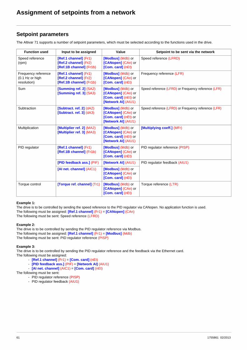
Assignment of setpoints from a network
Setpoint parametersThe Altivar 71 supports a number of setpoint parameters, which must be selected according to the functions used in the drive.
Example 1:The drive is to be controlled by sending the speed reference to the PID regulator via CANopen. No application function is used. The following must be assigned: [Ref.1 channel] (Fr1) = [CANopen] (CAn)The following must be sent: Speed reference (LFRD)
Example 2:The drive is to be controlled by sending the PID regulator reference via Modbus.The following must be assigned: [Ref.1 channel] (Fr1) = [Modbus] (Mdb)The following must be sent: PID regulator reference (PISP)
Example 3:The drive is to be controlled by sending the PID regulator reference and the feedback via the Ethernet card.The following must be assigned:
- [Ref.1 channel] (Fr1) = [Com. card] (nEt)- [PID feedback ass.] (PIF) = [Network AI] (AIU1)- [AI net. channel] (AIC1) = [Com. card] (nEt)
The following must be sent:- PID regulator reference (PISP)- PID regulator feedback (AIU1)
Function used Input to be assigned Value Setpoint to be sent via the network
Speed reference(rpm)
[Ref.1 channel] (Fr1)[Ref.2 channel] (Fr2)[Ref.1B channel] (Fr1b)
[Modbus] (Mdb) or [CANopen] (CAn) or [Com. card] (nEt)
Speed reference (LFRD)
Frequency reference(0.1 Hz or high resolution)
[Ref.1 channel] (Fr1)[Ref.2 channel] (Fr2)[Ref.1B channel] (Fr1b)
[Modbus] (Mdb) or [CANopen] (CAn) or [Com. card] (nEt)
Frequency reference (LFR)
Sum [Summing ref. 2] (SA2) [Summing ref. 3] (SA3)
[Modbus] (Mdb) or [CANopen] (CAn) or [Com. card] (nEt) or [Network AI] (AIU1)
Speed reference (LFRD) or Frequency reference (LFR)
Subtraction [Subtract. ref. 2] (dA2) [Subtract. ref. 3] (dA3)
[Modbus] (Mdb) or [CANopen] (CAn) or [Com. card] (nEt) or [Network AI] (AIU1)
Speed reference (LFRD) or Frequency reference (LFR)
Multiplication [Multiplier ref. 2] (MA2) [Multiplier ref. 3] (MA3)
[Modbus] (Mdb) or [CANopen] (CAn) or [Com. card] (nEt) or [Network AI] (AIU1)
[Multiplying coeff.] (MFr)
PID regulator [Ref.1 channel] (Fr1)[Ref.1B channel] (Fr1b)
[Modbus] (Mdb) or [CANopen] (CAn) or [Com. card] (nEt)
PID regulator reference (PISP)
[PID feedback ass.] (PIF) [Network AI] (AIU1) PID regulator feedback (AIU1)
[AI net. channel] (AIC1) [Modbus] (Mdb) or [CANopen] (CAn) or [Com. card] (nEt)
Torque control [Torque ref. channel] (Tr1) [Modbus] (Mdb) or [CANopen] (CAn) or [Com. card] (nEt)
Torque reference (LTR)
61 1755861 02/2013

Assignment of setpoints from a network
Without PID regulator
���
���
����
���
���
��
���
�
��
�
��
��
���
���
����
+/- speed around a reference
Preset speeds
Jog operation
PID not assigned
Graphic display terminal
Forced local
Ramps
Parameter:The black square represents the factory setting assignment.
Key:
Cha
nnel
1
Cha
nnel
2
[Ref 1B switching]
[Ref.1 channel]
[Ref.1B channel]
[Summing ref. 2]
[Summing ref. 3]
[Subtract. ref. 2]
[Subtract. ref. 3]
[Multiplier ref. 2]
[Low speed]
[Multiplier ref. 3]
[PID REGULATOR]
AI1
[Ref.2 channel]
[Ref. 2 switching]
(FR
A +
SA2
+ S
A3 -
dA2
- dA
3) x
MA
2 x
MA
3
(SP1)
SP2
SP16LI
LCC
FRA
nO
[Highspeed]
nO
nO
nOnO
FrH
AI2
AI3
HSP
LSP
ACC DEC
AC2 DE2
LI
AI4
nO0V
Note: Forced local is not active in [I/O profile].
FrO
FrOd
Powerstage M
rFr
rFrd
FrHd
Network referencesFr1, Fr1b, Fr2:
• LFr or LFrdSA2, SA3, dA2, dA3:
• LFr, LFrd, or AIU1MA2, MA3:
• MFr or AIU1
62 1755861 02/2013

Assignment of setpoints from a network
With PID regulator
(1)Ramp AC2 is only active at startup of the PID function and during PID "wake-ups".
���
���
����
���
���
���
��
�
��
�
���
����
Graphic display terminal
Ramps (1)
Channel 1
Channel 2
PIDSee diagram
below
A
Forced local
[Ref 1B switching]
[Ref.1 channel]
[Ref.1B channel]
[Summing ref. 2]
[Summing ref. 3]
[Subtract. ref. 2]
[Subtract. ref. 3]
[Low speed]
AI1
[Ref.2 channel]
[Ref. 2 switching]
FRA
+ S
A2
+ SA
3 - d
A2
- dA3
B
LCC
PIP1
[Highspeed]
nOFrH FrO
AI2
AI3
HSP
LSP
ACC DEC
AC2 DE2
LI
AI4
nO0V
Note: Forced local is not active in [I/O profile].
FrHd FrOd
Powerstage M
rFr
rFrd
PIP2
Network referencesFr1, Fr1b:
• PISPSA2, SA3, dA2, dA3:
• LFr, LFrd, or AIU1Fr2, FPI:
• LFr or LFrd
Network feedback• AIU1
PAU
(manu)
Pr2
Pr4
nO +
-rP2
rP3
rP4
rIGrPG
PIF
PIN
0
tLS
rSL
PIF1 / PIF2PIP1 / PIP2
x(-1)
nO
nO
YES
PIC
nO
AI1.....
AI4
LI
+
+
POH
POL
rdG
ACC DECFPI x PSr
PII
SP2
SP16
rPI
A B
nO
YESPrP
AC2(1)
Internalreference
PIDfeedback
Preset PID references
Error inversion
Restart (wake-up) error
threshold
Gains
Ramps
Parameter:The black rectangle represents the factory setting assignment.
Key:
Ramp
Preset manual references
Scaling
[RP] (PI)[Encoder] (PG)
[Network AI](AIU1)
Predictivespeedreference
Manual reference
Auto/Manual
rPC
rPF
rPO
rPE
1755861 02/2013 63

Configuration saving and switching
Saving the configurationWhen a parameter is modified via the drive’s integrated display terminal or graphic display terminal, this parameter is automatically savedto the EEPROM non-volatile memory.
When a parameter is modified using a PLC or an HMI terminal via a network (Modbus, CANopen or a network card), this parameter is writtento the current configuration in the RAM volatile memory. It is not saved to the EEPROM non-volatile memory. If the drive control voltage isdisconnected, when it is reconnected, the parameter reverts to the initial value and the setting is lost.
Display terminal
Current configuration
(RAM)
Configuration 0(EEPROM)
Configuration 1(EEPROM)
Configuration 2(EEPROM)
Factory settings
Display terminal
Configuration 0(EEPROM)
Configuration 1(EEPROM)
Configuration 2(EEPROM)
Factory settings
Current configuration
(RAM)
No
IndustrialHMI
terminal
PLC
Modbus
CANopen
Network
1755861 02/2013 64

Configuration saving and switching
To save the parameter, a save command must be executed using bit 1 of the extended control word (CMI).
The save command is only active if the drive is stopped and not in "5-Operation enabled" state.
Display terminal
Configuration 0(EEPROM)
Configuration 1(EEPROM)
Configuration 2(EEPROM)
Factory settings
IndustrialHMI
terminal
PLC
Modbus
CANopen
Network
Current configuration
(RAM)
Extended control word:Save (CMI,1)
Set to 1
1755861 02/2013 65

Configuration saving and switching
Restore configurationThe restore configuration command is executed using bit 2 of the extended control word (CMI).
The return to factory settings command is executed using bit 0 of the extended control word (CMI). The type of setting is determined by theactive macro configuration parameter [Macro configuration] (CFG) and by the [PARAMETER GROUP LIST] (FrY) parameter whichdefines the parameter groups concerned.
The restore command is only active if the drive is stopped and not in "5-Operation enabled" state.
Display terminal
Configuration 0(EEPROM)
Configuration 1(EEPROM)
Configuration 2(EEPROM)
Factory settings
IndustrialHMI
terminal
PLC
Modbus
CANopen
Network
Current configuration
(RAM)
Extended control word:Restore configuration (CMI,2)
Set to 1
Display terminal
Configuration 0(EEPROM)
Configuration 1(EEPROM)
Configuration 2(EEPROM)
Factory settings
IndustrialHMI
terminal
PLC
Modbus
CANopen
Network
Current configuration
(RAM)
Extended control word:Factory setting (CMI,0)
Set to 1
[Macro configuration](CFG)
66 1755861 02/2013

Configuration saving and switching
Configuration switching via control wordThe configuration or motor switching function (see the Programming Manual) can be used via the network or via the terminals.
To use this function via a network, simply assign one or two bits of the control word to the motor or configuration switching command viathe [2 Configurations] (CnF1) and [3 Configurations] (CnF2) parameters.The active configuration can be read in the [Config. active] (CNFS) parameter.
Display terminal
Configuration 0(EEPROM)
Configuration 1(EEPROM)
Configuration 2(EEPROM)
Factory settings
Current configuration
(RAM)
Configuration switching[2 Configurations](CnF1)[3 configurations](CnF2)
Activeconfiguration
(CNFS)
Terminals
00 01 1011
Configuration 0(EEPROM)
Configuration 2(EEPROM)
Display terminal
Configuration 1(EEPROM)
Factory settings
Current configuration
(RAM)
Control word:Configuration switching
[2 Configurations](CnF1)[3 configurations](CnF2)
Activeconfiguration
(CNFS) 00 01 1011
IndustrialHMI
terminal
PLC
Modbus
CANopen
Network
Set to 0/1
1755861 02/2013 67

Configuration saving and switching
When the configuration or motor switching function is configured on inputs or on control word bits, to save a configuration that is alreadyactive, set bit 1 of the extended control word (CMI) to 1.
When the configuration or motor switching function is configured on inputs or on control word bits, bit 2 of the extended control word (CMI)must be set to 1.
The configuration switching commands are only active if the drive is stopped and not in "5-Operation enabled" state.
Configuration 0(EEPROM)
Configuration 2(EEPROM)
PLC
IndustrialHMI
terminal
Display terminal
Configuration 1(EEPROM)
Factory settings
Current configuration
(RAM)
Extended control word:Save configuration (CMI,1)
Activeconfiguration
(CNFS)
Modbus
CANopen
Network
Set to 1
1 2 3
Extended control word:Restore configuration (CMI,2)
Set to 1
Display terminal
Configuration 0(EEPROM)
Configuration 1(EEPROM)
Configuration 2(EEPROM)
Factory settings
Current configuration
(RAM)
Activeconfiguration
(CNFS)
IndustrialHMI
terminal
PLC
Modbus
CANopen
Network
1 2 3
68 1755861 02/2013

Configuration saving and switching
Function parameters
Code Description
CNF1 Parameter name: Assignment for 2 configurations
Terminal display: [2 Configurations]
Logic address: 8021 = 16#1F55 Type: WORD (listing)
CANopen index: 2032/16 Read/write: R/WS
INTERBUS index: 5FBC/9C Factory setting: 0
DeviceNet path: 9C/01/9C
See next page.
CNF2 Parameter name: Assignment for 3 configurations
Terminal display: [3 Configurations]
Logic address: 8022 = 16#1F56 Type: WORD (listing)
CANopen index: 2032/17 Read/write: R/WS
INTERBUS index: 5FBC/9D Factory setting: 0
DeviceNet path: 9C/01/9D
See next page.
CNFS Parameter name: Active configuration
Terminal display: [Config. active]
Logic address: 8020 = 16#1F54 Type: WORD (listing)
CANopen index: 2032/15 Read/write: R
INTERBUS index: 5FB9/CD
DeviceNet path: 89/01/15
0 = The parameter set switching function is not configured1 = (CNF0): Configuration no. 0 active2 = (CNF1): Configuration no. 1 active3 = (CNF2): Configuration no. 2 active
Value of the control bit assigned by [2 Configurations] (CnF1) 0 1 0 1
Value of the control bit assigned by [3 Configurations] (CnF2) 0 0 1 1
Value of [Config. active] (CnFS) 1 2 3 3
Active configuration 0 1 2 2
1755861 02/2013 69

Configuration saving and switching
Assignment of logic inputs and control bits for CNF1 and CNF2
Note: In [I/O profile] (IO), LI1 cannot be accessed and if [2/3 wire control] (tCC) = [3 wire] (3C), LI2 cannot be accessed either.
Value Assignment Description/Condition
0 Not assigned
129 to
134
[LI1] (LI1) to
[LI6] (LI6)
Logic inputs
Drive with or without option
135to
138
[LI7] (LI7) to
[LI10] (LI10)
Logic inputs
With VW3A3201 logic I/O card
139 to
142
[LI11] (LI11) to
[LI14] (LI14)
Logic inputs
With VW3A3202 extended I/O card
187 to
191
[C111] (C111) to
[C115] (C115)
Control bit
With integrated Modbus regardless of profile
203to
207
[C211] (C211) to
[C215] (C215)
Control bit
With integrated CANopen regardless of profile
219to
223
[C311] (C311) to
[C315] (C315)
Control bit
With a communication card regardless of profile
235to
239
[C411] (C411) to
[C415] (C415)
Control bit
With Controller Inside card regardless of profile
70 1755861 02/2013

Configuration saving and switching
Configuration switching by selectionThe current configuration can be saved in one of the 3 non-volatile configurations in EEPROM using the "Save configuration" (SCS)parameter. In this case, it is not necessary to assign a function in the control word.
One of the 3 non-volatile configurations in EEPROM can be restored to the current configuration using the "Restore configuration" (FCS)parameter.Note: Value 64 controls the return to factory settings.
The configuration switching commands are only active if the drive is stopped and not in "5-Operation enabled" state.
Display terminal
Configuration 0(EEPROM)
Configuration 1(EEPROM)
Configuration 2(EEPROM)
Factory settings
Current configuration
(RAM)
Save configuration (SCS)
IndustrialHMI
terminal
PLC
Modbus
CANopen
Network
Write
1 2 3
Display terminal
Configuration 0(EEPROM)
Configuration 1(EEPROM)
Configuration 2(EEPROM)
Factory settings
Current configuration
(RAM)
Restore configuration(FCS)
IndustrialHMI
terminal
PLC
Modbus
CANopen
Network
Write
1 2 3 64
[Macro configuration](CFG)
1755861 02/2013 71

Configuration saving and switching
Function parameters
Code Description
SCS Parameter name: Save configuration
Logic address: 8001 = 16#1F41 Type: WORD (listing)
CANopen index: 2032/2 Read/write: R/WS
INTERBUS index: 5FBC/9A
DeviceNet path: 9C/01/9A
0 = No save1 = Save to configuration no. 02 = Save to configuration no. 13 = Save to configuration no. 2
FCS Parameter name: Restore configuration
Logic address: 8002 = 16#1F42 Type: WORD (listing)
CANopen index: 2032/3 Read/write: R/WS
INTERBUS index: 5FBC/9B
DeviceNet path: 9C/01/9B
0 = No restore1 = Restore configuration no. 02 = Restore configuration no. 13 = Restore configuration no. 2
64 = Factory setting
FrY Parameter name: Parameter group list
Terminal display: [PARAMETER GROUP LIST]
Logic address: 3022 = 16#OBCE Type: WORD (bit register)
CANopen index: 2000/17 Read/write: R/WS
INTERBUS index: 5FBC/06 Factory setting: 0
DeviceNet path: 70/01/17
Selection of menus to be loadedBit 0: = 1: [All] (ALL) : All parametersBit 1: = 1: [Drive menu] (drM): The [1 DRIVE MENU] menu without [1.9 COMMUNICATION] and [1.14 CONTROL
INSIDE MENU]. In the [7 DISPLAY CONFIG.] menu, [Return std name] returns to [No].Bit 2: = 1: [Settings] (SEt): The [1.3 SETTINGS] menu without the [IR compensation] (UFr), [Slip compensation]
(SLP) and [Mot. therm. current] (ItH) parameters.Bit 3: = 1: [Motor param] (MOt): Motor parameters:
[Rated motor power] (nPr) - [Rated motor volt.] (UnS) - [Rated mot. current] (nCr) - [Rated motor freq.] (FrS) -[Rated motor speed] (nSP) - [Auto tuning] (tUn) - [Auto tuning state] (tUS) - [U0] (U0) to [U5] (U5) - [Freq pt1on 5pt V/F] (F1) to [F5] (F5) - [V. constant power] (UCP) - [Freq. Const Power] (FCP) - [Nominal I sync.](nCrS) - [Nom motor spdsync] (nSPS) - [Pole pairs] (PPnS) - [Syn. EMF constant] (PHS) - [Autotune L d-axis](LdS) - [Autotune L q-axis] (LqS) - [Cust. stator R syn] (rSAS) - [IR compensation] (UFr) - [Slip compensation](SLP) - the motor parameters that can be accessed in [Expert] mode.
The following selections can only be accessed if [Config. Source] (FCSI) = [Macro-Conf] (InI):Bit 4: = 1: [Comm. menu] (COM): The [1.9 COMMUNICATION] menu without either [Scan. IN1 address] (nMA1) to
[Scan. IN8 address] (nMA8) or [Scan.Out1 address] (nCA1) to [Scan.Out8 address] (nCA8).Bit 5: = 1: [Control Inside menu] (PLC): The [1.14 CONTROL INSIDE MENU] menuBit 6: = 1: [Monitor config.] (MOn): The [6 MONITORING CONFIG.] menuBit 7: = 1: [Display config.] (dIS): The [7 DISPLAY CONFIG.] menu
Bits 8 to 15: Reserved (= 0 or 1)
72 1755861 02/2013

Parameter set switching
The parameter set switching function (see the Programming Manual) can be used via the network or via the terminals.
To use this function via a network, simply assign one or two bits of the control word to parameter set switching via the [2 Parameter sets](CHA1) and [3 Parameter sets] (CHA2) parameters.
The active set can be read in the "Active parameter set" (CFPS) parameter.
The parameter sets can be written via a network.
The parameter sets can be switched with the motor running.
Function parameters
Code Description
CHA1 Parameter name: Assignment for 2 sets
Terminal display: [2 Parameter sets]
Logic address: 12902 = 16#3266 Type: WORD (listing)
CANopen index: 2063/3 Read/write: R/WS
INTERBUS index: 5FBD/54 Factory setting: 0
DeviceNet path: A1/01/67
See next page.
CHA2 Parameter name: Assignment for 3 sets
Terminal display: [3 Parameter sets]
Logic address: 12903 = 16#3267 Type: WORD (listing)
CANopen index: 2063/4 Read/write: R/WS
INTERBUS index: 5FBD/55 Factory setting: 0
DeviceNet path: A1/01/68
See next page.
CFPS Parameter name: Active parameter set
Logic address: 12900 = 16#3264 Type: WORD (listing)
CANopen index: 2063/1 Read/write: R
INTERBUS index: 5FB9/EC
DeviceNet path: A1/01/65
0 = The parameter set switching function is not configured1 = [Set 1 active] (CFP1): Parameter set no. 1 active2 = [Set 2 active] (CFP2): Parameter set no. 2 active3 = [Set 3 active] (CFP3): Parameter set no. 3 active
Value of the control bit assigned by [2 Parameter sets] (CHA1) 0 1 0 1
Value of the control bit assigned by [3 Parameter sets] (CHA2) 0 0 1 1
Value of "Active parameter set" (CFPS) 1 2 3 3
Active parameter set 1 2 3 3
73 1755861 02/2013

Parameter set switching
CHA1 and CHA2 assignment values
Note: In [I/O profile] (IO), LI1 cannot be accessed and if [2/3 wire control] (tCC) = [3 wire] (3C), LI2, C101, C201, C301 and C401cannot be accessed either.
Value Assignment Description/Condition
0 [No] (nO) Not assigned
4 [Freq. Th. attain.] (FtA) Switching via [Freq. threshold] (Ftd)
13 [Freq. Th. 2 attain.] (F2A)
Switching via [Freq. threshold 2] (F2d)
129 to
134
[LI1] (LI1) to
[LI6] (LI6)
Logic inputs
Drive with or without option
135to
138
[LI7] (LI7) to
[LI10] (LI10)
Logic inputs
With VW3A3201 logic I/O card
139 to
142
[LI11] (LI11) to
[LI14] (LI14)
Logic inputs
With VW3A3202 extended I/O card
160to
170
[CD00] (Cd00) to
[CD10] (Cd10)
Switchable bit
In [I/O profile] (IO)
171to
175
[CD11] (Cd11) to
[CD15] (Cd15)
Switchable bit
Regardless of profile
177 to
186
[C101] (C101) to
[C110] (C110)
Control bit
With integrated Modbus in [I/O profile] (IO)
187 to
191
[C111] (C111) to
[C115] (C115)
Control bit
With integrated Modbus regardless of profile
193to
202
[C201] (C201) to
[C210] (C210)
Control bit
With integrated CANopen in [I/O profile] (IO)
203to
207
[C211] (C211) to
[C215] (C215)
Control bit
With integrated CANopen regardless of profile
209to
218
[C301] (C301) to
[C310] (C310)
Control bit
With a communication card in [I/O profile] (IO)
219to
223
[C311] (C311) to
[C315] (C315)
Control bit
With a communication card regardless of profile
225to
234
[C401] (C401) to
[C410] (C410)
Control bit
With Controller Inside card in [I/O profile] (IO)
235to
239
[C411] (C411) to
[C415] (C415)
Control bit
With Controller Inside card regardless of profile
74 1755861 02/2013

Parameter set switching
Parameter sets can be loaded via the following parameters:
Address table:
Table of values for set no. 1:
No. Code Logic address: CANopen index: INTERBUS index: DeviceNet path:
1 AD01 12911 = 16#326F 2063/C 5FBF/8C 9F/01/8C
2 AD02 12912 = 16#3270 2063/D 5FBF/8D 9F/01/8D
3 AD03 12913 = 16#3271 2063/E 5FBF/8E 9F/01/8E
4 AD04 12914 = 16#3272 2063/F 5FBF/8F 9F/01/8F
5 AD05 12915 = 16#3273 2063/10 5FBF/90 9F/01/90
6 AD06 12916 = 16#3274 2063/11 5FBF/91 9F/01/91
7 AD07 12917 = 16#3275 2063/12 5FBF/92 9F/01/92
8 AD08 12918 = 16#3276 2063/13 5FBF/93 9F/01/93
9 AD09 12919 = 16#3277 2063/14 5FBF/94 9F/01/94
10 AD10 12920 = 16#3278 2063/15 5FBF/95 9F/01/95
11 AD11 12921 = 16#3279 2063/16 5FBF/96 9F/01/96
12 AD12 12922 = 16#327A 2063/17 5FBF/97 9F/01/97
13 AD13 12923 = 16#327B 2063/18 5FBF/98 9F/01/98
14 AD14 12924 = 16#327C 2063/19 5FBF/99 9F/01/99
15 AD15 12925 = 16#327D 2063/1A 5FBF/9A 9F/01/9A
No. Code Logic address: CANopen index: INTERBUS index: DeviceNet path:
1 S101 12931 = 16#3283 2063/20 5FBF/9B 9F/01/9B
2 S102 12932 = 16#3284 2063/21 5FBF/9C 9F/01/9C
3 S103 12933 = 16#3285 2063/22 5FBF/9D 9F/01/9D
4 S104 12934 = 16#3286 2063/23 5FBF/9E 9F/01/9E
5 S105 12935 = 16#3287 2063/24 5FBF/9F 9F/01/9F
6 S106 12936 = 16#3288 2063/25 5FBF/A0 9F/01/A0
7 S107 12937 = 16#3289 2063/26 5FBF/A1 9F/01/A1
8 S108 12938 = 16#328A 2063/27 5FBF/A2 9F/01/A2
9 S109 12939 = 16#328B 2063/28 5FBF/A3 9F/01/A3
10 S110 12940 = 16#328C 2063/29 5FBF/A4 9F/01/A4
11 S111 12941 = 16#328D 2063/2A 5FBF/A5 9F/01/A5
12 S112 12942 = 16#328E 2063/2B 5FBF/A6 9F/01/A6
13 S113 12943 = 16#328F 2063/2C 5FBF/A7 9F/01/A7
14 S114 12944 = 16#3290 2063/2D 5FBF/A8 9F/01/A8
15 S115 12945 = 16#3291 2063/2E 5FBF/A9 9F/01/A9
1755861 02/2013 75

Parameter set switching
Table of values for parameter set no. 2:
Table of values for set no. 3:
No. Code Logic address: CANopen index: INTERBUS index: DeviceNet path:
1 S201 12951 = 16#3297 2063/34 5FBF/AA 9F/01/AA
2 S202 12952 = 16#3298 2063/35 5FBF/AB 9F/01/AB
3 S203 12953 = 16#3299 2063/36 5FBF/AC 9F/01/AC
4 S204 12954 = 16#329A 2063/37 5FBF/AD 9F/01/AD
5 S205 12955 = 16#329B 2063/38 5FBF/AE 9F/01/AE
6 S206 12956 = 16#329C 2063/39 5FBF/AF 9F/01/AF
7 S207 12957 = 16#329D 2063/3A 5FBF/B0 9F/01/B0
8 S208 12958 = 16#329E 2063/3B 5FBF/B1 9F/01/B1
9 S209 12959 = 16#329F 2063/3C 5FBF/B2 9F/01/B2
10 S210 12960 = 16#32A0 2063/3D 5FBF/B3 9F/01/B3
11 S211 12961 = 16#32A1 2063/3E 5FBF/B4 9F/01/B4
12 S212 12962 = 16#32A2 2063/3F 5FBF/B5 9F/01/B5
13 S213 12963 = 16#32A3 2063/40 5FBF/B6 9F/01/B6
14 S214 12964 = 16#32A4 2063/41 5FBF/B7 9F/01/B7
15 S215 12965 = 16#32A5 2063/42 5FBF/B8 9F/01/B8
No. Code Logic address: CANopen index: INTERBUS index: DeviceNet path:
1 S301 12971 = 16#32AB 2063/48 5FBF/B9 9F/01/B9
2 S302 12972 = 16#32AC 2063/49 5FBF/BA 9F/01/BA
3 S303 12973 = 16#32AD 2063/4A 5FBF/BB 9F/01/BB
4 S304 12974 = 16#32AE 2063/4B 5FBF/BC 9F/01/BC
5 S305 12975 = 16#32AF 2063/4C 5FBF/BD 9F/01/BD
6 S306 12976 = 16#32B0 2063/4D 5FBF/BE 9F/01/BE
7 S307 12977 = 16#32B1 2063/4E 5FBF/BF 9F/01/BF
8 S308 12978 = 16#32B2 2063/4F 5FBF/C0 9F/01/C0
9 S309 12979 = 16#32B3 2063/50 5FBF/C1 9F/01/C1
10 S310 12980 = 16#32B4 2063/51 5FBF/C2 9F/01/C2
11 S311 12981 = 16#32B5 2063/52 5FBF/C3 9F/01/C3
12 S312 12982 = 16#32B6 2063/53 5FBF/C4 9F/01/C4
13 S313 12983 = 16#32B7 2063/54 5FBF/C5 9F/01/C5
14 S314 12984 = 16#32B8 2063/55 5FBF/C6 9F/01/C6
15 S315 12985 = 16#32B9 2063/56 5FBF/C7 9F/01/C7
76 1755861 02/2013

Parameter set switching
Code Description
VAL Parameter name: Load parameter set command
Logic address: 12901 = 16#3265 Type: WORD (listing)
CANopen index: 2063/02 Read/write: R/W
INTERBUS index:
DeviceNet path: A1/01/66
0 = Function not used or a new set of parameters has been taken into account1 = Request to write a new set of parameters2 = A new set of parameters is being written
Procedure:• Write the addresses and values of the sets.• Set VAL to 1.• Once the new sets have been taken into account, the drive resets (VAL) to 0.
1755861 02/2013 77

Parameter set switching
78 1755861 02/2013

Loading drive parameters
RequirementCertain applications require parameters to be downloaded:
• When the installation starts up• When the manufacturing range is changed• When a faulty device is replaced
Neither the integrated ports nor the network cards of the drive provide a parameter file loading procedure (except for the faulty devicereplacement (FDR) mechanism of the VW3 A3 310 Modbus Ethernet TCP/IP card).
Parameter loading is therefore based on write requests that have to be programmed in the controller (PLC, etc.).
If the controller is limited to writing parameters sequentially, the final configuration risks not being identical to the one desired.The differences between the configuration to be loaded and the real configuration result from consistency checking of the drive parameters.The drive checks relationships between the parameters, and if they are not correct:
• It automatically modifies a parameter which is offered for writing (pedestal, deadband) or• Writing of the parameter is rejected
Examples illustrating this problem are given on page 80.
The controller must therefore follow a procedure that includes a phase of disabling the consistency check function.
ProcedureAll the operations described below must be carried out with the motor stopped, with no run command to the drive.
Saving the reference configuration1. Identify the parameters of the reference drive that differ from the factory setting. These parameters can be identified easily using the
PowerSuite software (which displays the list of parameters).
2. Reserve a parameter map table in the controller (PLC, etc.). This map table is a series of addresses and values. The last parameter to be loaded is identified by an address equal to -1.
3. Enter the addresses of the modified parameters into the controller's map table by copying the list given by the PowerSuite software.
4. Initialize the values in the map table. There are two possible methods:- Enter the values manually.- Program an automatic read function in the controller. Connect the controller to the reference drive. Save the reference
configuration in the map table.
Loading the configurationThe program in the controller (PLC, etc.) must perform the following operations:1. Command a drive factory setting:
Write the value 16#0001 to the extended control word (8504-CMI).
2. Disable the parameter consistency check function:Write the value 16#8000 to the extended control word (8504-CMI).
3. Load the configuration:Write the parameters one after another using the map table.
4. Enable the parameter consistency check function:Write the value 16#0000 to the extended control word (8504-CMI).
5. Check the drive configuration:Read and compare the parameters one after another against the map table.
1755861 02/2013 79

Loading drive parameters
Inconsistency examplesThe two adjustment parameters [Low speed] (3105-LSP) and [High speed] (3104-HSP) comply with the consistency rule: 0 y [Low speed] (3105-LSP) y [High speed] (3104-HSP) y 16000.
Example 1Initial configuration V Configuration to be loaded:[High speed] (3104-HSP) = 30 Hz V [High speed] (3104-HSP) = 60 Hz[Low speed] (3105-LSP) = 20 Hz V [Low speed] (3105-LSP) = 40 Hz
• "Request n: Request to write [Low speed] (3105-LSP) to 40 Hz• "Consistency check: The consistency rule [Low speed] (3105-LSP) y [High speed] (3104-HSP) has not been observed:
- The [Low speed] (3105-LSP) parameter actually written into the drive is 30 Hz.
• "Request n+1: Request to write [High speed] (3104-HSP) = 60 Hz• "Consistency check: The consistency rules have been observed:
- The [High speed] (3104-HSP) parameter is correctly written as 60 Hz in the drive.
The loaded configuration differs from the configuration to be loaded:[Low speed] (3105-LSP) = 30 Hz instead of [Low speed] (3105-LSP) = 40 HzThe drive can operate between 30 Hz and 40 Hz, which is not desired.
Example 2Initial configuration V Configuration to be loaded:[High speed] (3104-HSP) = 60 Hz V [High speed] (3104-HSP) = 30 Hz[Low speed] (3105-LSP) = 40 Hz V [Low speed] (3105-LSP) = 0 Hz
• "Request n: Request to write [High speed] (3104-HSP) to 30 Hz • "Consistency check: The consistency rule [Low speed] (3105-LSP) y [High speed] (3104-HSP) has not been observed:
- The [High speed] (3104-HSP) parameter actually written into the drive is 40 Hz.
• "Request n+1: Request to write [Low speed] (3105-LSP) = 0 Hz• "Consistency check: The consistency rules have been observed:
- The [Low speed] (3104-HSP) parameter is correctly written as 0 Hz in the drive.
The loaded configuration differs from the configuration to be loaded:[High speed] (3104-HSP) = 40 Hz instead of [High speed] (3104-HSP) = 30 HzThe drive can operate between 30 Hz and 40 Hz, which is not desired.
80 1755861 02/2013

Command parameters
Code Description
CMd Parameter name: Control word
Terminal display: [Cmd value]
CiA402 name: controlword
DRIVECOM name: Control word
Logic address: 8601 = 16#2199or 8501 = 16#2135 (1)
Type: WORD (bit register)
CANopen index: 6040/0 Read/write: R/W
INTERBUS index: 6040/0
DeviceNet path: B7/01/01
(1)Note: This parameter is available at two logic addresses to optimize exchanges via Modbus messaging (Modbusfunction 16 = 16#10 Write Multiple Registers):
- If the drive has to be controlled in terms of speed, it is preferable to use address 8601, since the speed reference is at address 8602.
- If the drive has to be controlled in terms of frequency, it is preferable to use address 8501, since the frequency reference is at address 8502.
Parameter conforming to CiA402 profile
Possible values in the IO profile
On state command [2 wire] (2C)bit 0: Forward (on state) command
= 0: No forward command= 1: Forward command
On edge command [3 wire] (3C)bit 0: Stop (run authorization)
= 0: Stop= 1: Run is authorized on a forward or reverse command
bit 1: Forward (on 0 V 1 rising edge) command
The assignment of bit 0 cannot be modified. It corresponds tothe assignment of the terminals. It can be switched. Bit 0(Cd00) is only active if the channel of this control word isactive.
The assignment of bits 0 and 1 cannot be modified. Itcorresponds to the assignment of the terminals. It can beswitched. Bits 0 (Cd00) and 1 (Cd01) are only active if thechannel of this control word is active.
Bits 1 to 15 can be assigned to commands. Bits 2 to 15 can be assigned to commands.
For example, to change the direction of operation using bit 2 of the control word of the active channel, simply configure the[Reverse assign.] (rrS) parameter:
• To the value [C102] (C102) ... [C402] (C402) for a fixed assignment• To the value [CD02] (Cd02) for a switched assignment
The stop commands:• Freewheel stop [Freewheel stop ass.] (nSt)• Fast stop [Fast stop assign.] (FSt) are active at value 0, in the same way as on the terminals.
= 0: Stop= 1: No stop command
DC injection braking [DC injection assign.] (dCI) is active at value 1, in the same way as on the terminals.= 0: No braking command= 1: Braking
If a fixed assignment is made [C101] (C101) to [C115] (C115) ... [C401] (C401) to [C415] (C415), the freewheel stop, faststop and DC injection braking commands are always active, even if the channel is not active. If these commands areconfigured as fixed assignments, the following settings must be made in order to start, even if another channel is active:
• Freewheel stop = 1• Fast stop = 1• DC injection braking = 0
If a switched assignment is made [CD00] (Cd00) to [Cd15] (Cd15) the freewheel stop, fast stop and DC injection brakingcommands are only active if the channel is active.
1755861 02/2013 81

Command parameters
Possible values in CiA402 profile, separate or not separate modebit 0: "Switch on"/Contactor commandbit 1: "Disable voltage"/Authorization to supply AC powerbit 2: "Quick stop"/Emergency stopbit 3: "Enable operation"/Run command
bit 4: Reserved (set to 0)bit 5: Reserved (set to 0)bit 6: Reserved (set to 0)bit 7: "Fault reset"/Fault acknowledgment active on 0 V 1 rising edge
bit 8: Halt Stop according to the [Type of stop] (Stt) parameter without leaving the 5 - Operation enabled statebit 9: Reserved (set to 0)
bit 10: Reserved (set to 0)bit 11: Direction of rotation command Default assignment; this bit can be assigned to another command.
= 0: Forward rotation= 1: Reverse rotation
bit 12: Can be assigned to a commandbit 13: Can be assigned to a commandbit 14: Can be assigned to a commandbit 15: Can be assigned to a command
For the description of bits 0, 1, 2, 3, 7 and 8, see the "CiA402 profile" section.
The CiA402 standard enables the drive manufacturer to use bits 11 to 15 in a specific way. On the Altivar 71, they can beassigned to function commands. Bit 11 is assigned by default to control the direction of rotation, although it can be assignedto another command. A new assignment deletes the assignment to the direction of rotation command. Bits 12 to 15 have nodefault assignment. For example, to control DC injection braking using bit 12 of the Modbus control word, simply set the[DC injection assign.] (dCI)) parameter to value [C212] (C212).
The fast stop command configured by [Fast stop assign.] (FSt) is active at 1:= 0: No stop command= 1: Stop
The DC injection braking command configured by [DC injection assign.] (dCI) is active at 1:= 0: No braking command= 1: Braking
With a fixed assignment ([C1pp], [C2pp], [C3pp] or [C4pp]), the fast stop and DC injection braking commands are prioritystops, even if the channel is not active. If these commands are configured as fixed assignments, the following settings mustbe made in order to start, even if another channel is active:
• Fast stop command = 0• DC injection braking command = 0
With a switched assignment ([Cdpp]), the fast stop and DC injection braking commands are only operational if the channelis active.
The freewheel stop [Freewheel stop ass.] (nSt) command cannot be assigned in CiA402 profile.
Code Description
82 1755861 02/2013

Command parameters
CMI Parameter name: Extended control word
Logic address: 8504 = 16#2138 Type: WORD (bit register)
CANopen index: 2037/5 Read/write: R/W
INTERBUS index: 5FB6/1E
DeviceNet path: 8B/01/69
bit 0: RAM factory setting command according to the [PARAMETER GROUP LIST] (FrY) parameter (active at 1). If youalso wish to return the EEPROM to the factory setting, bit 1 must also be set to 1 (both commands can be executedsimultaneously).
bit 1: Save configuration to EEPROM non-volatile memory command (active at 1).This bit automatically changes to 0 after the request is taken into account. The command is only active if the driveis stopped, and not in "5-Operation enabled" state.Note: If CMI is a periodic network variable, the PLC program must write it to 0 after the first request is taken into
account. The life of the EEPROM memory is limited to 100,000 write operations.Note: If the motor or configuration switching function is active, the configuration in the RAM is saved to the
EEPROM in the configuration designated by [Config. Active] (CnFS).bit 2: Restore configuration to EEPROM non-volatile memory command (active on 0 to 1 rising edge).
This bit automatically changes to 0 after the request is taken into account.The command is only active if the drive is stopped, and not in "5-Operation enabled" state.Note: If CMI is a periodic network variable, the PLC program must write it to 0 after the first request is taken into
account.This does not adversely affect the life of the EEPROM memory, but permanently copies the configurationin the memory to the current configuration.
Note: If the motor or configuration switching function is active, the configuration in the EEPROM designated by[Config. Active] (CnFS) is copied to the RAM.
bit 3: Reserved (= 0)
bit 4: Reserved (= 0)bit 5: Reserved (= 0)bit 6: Reserved (= 0)bit 7: Reserved (= 0)
bit 8: Reserved (= 0)bit 9: Definition of the frequency reference (LFr) and output frequency (rFr) unit:
=0: 0.1 Hz=1: Standardized value 16 signed bits based on the maximum frequency. The value 32767 corresponds to
[Max frequency] (tFr). The default value of [Max frequency] (tFr) is 60 Hz, and the resolution is thenapproximately 0.0018 Hz.This function has no effect on the speed reference (LFrd) or the output speed (rFrd).
bit 10: Fast stop command (active at 1)bit 11: DC injection braking command (active at 1). This command must no be used if [Motor control type] (Ctt) =
[Sync. mot.] (SYn).
bit 12: Direction of rotation command= 0: Forward= 1: Reverse
bit 13: Reserved (= 0)bit 14: Reserved (= 0)bit 15: Parameter consistency check
= 0: The check is activated. Each time a parameter is written, the drive checks the relationship between the writtenparameter and the configuration in the drive. For example, the [High speed] (HSP) parameter must be less thanthe [Max frequency] (tFr) parameter. If an attempt is made to write a value greater than the [Max frequency] (tFr)parameter to the [High speed] (HSP) parameter, the write operation is accepted, but the value is limited to that of[Max frequency] (tFr).
= 1: The check is deactivated. The drive is locked in stop mode. In this drive state, the configuration can be writtenparameter by parameter and the drive does not modify the values that are written.
1V0: The change from 1 to 0 triggers a calculation of the consistency of the configuration. Some parameters can bemodified automatically by the drive.
Code Description
1755861 02/2013 83

Setpoint parameters
See section “Assignment of setpoints from a network”, page 60
Code Description
LFRD Parameter name: Speed setpoint
CiA402 name: vl target velocity
DRIVECOM name: Speed-Setpoint
Logic address: 8602 = 16#219A Type: INT
CANopen index: 6042/0 Read/write: R/W
INTERBUS index: 6042/0 Unit: rpm
DeviceNet path: 2A/01/08 (1)8C/01/03 (2)
Parameter conforming to CiA402 and ODVA profilesSigned value. This parameter changes the direction of operation according to its sign.
LFR Parameter name: Frequency reference
Terminal display: [Frequency ref.]
Logic address: 8502 = 16#2136 Type: INT
CANopen index: 2037/3 Read/write: R/W
INTERBUS index: 5FB6/1C Unit: 0.1 Hz or standardized16 signed bits based on themaximum frequency (TFR)DeviceNet path: 8B/01/67
Signed value.The unit depends on the value of bit 9 of the extended control word (CMI):
= 0: 0.1 Hz= 1: High resolution: Standardized value at maximum frequency in 16 signed bits. The value 32767 = 16 # 7FFF
corresponds to [Max frequency] (tFr). The default value of [Max frequency] (tFr) is 60 Hz, and the resolution isthen approximately 0.0018 Hz.
LTR Parameter name: Torque reference
Terminal display: [HMI torque ref.]
CiA402 name: Target torque
DRIVECOM name: Torque-Setpoint-External
Logic address: 8505 = 16#2139 Type: INT
CANopen index: 6071/0 Read/write: R/W
INTERBUS index: 5FB6/1F Unit: 0.001 "Nominal motor torque"
DeviceNet path: 8B/01/6A
Parameter conforming to CiA402 profileSigned value.The "Nominal motor torque" is not accessible as a drive parameter. It is the result of a calculation on the other characteristics.
(1)ODVA standard path. It can be used for explicit messaging. Do not use it for configuring an assembly.(2)Altivar path. Avoid using it for explicit messaging, to ensure better interchangeability. This is the path that must be used for configuring
an assembly.
84 1755861 02/2013

Setpoint parameters
Int Parameter name: Torque unit
Logic address: 9260 = 16#242C Type: WORD (listing)
CANopen index: 203E/3D Read/write: R/WS
INTERBUS index: 5FBF/35 Factory setting: According to drive rating
DeviceNet path: 8F/01/3D
0 = 0.01 Nm1 = 0.1 Nm2 = 1 Nm3 = 10 Nm
This parameter is only used and can only be configured with DeviceNet. It sets the unit for the LTCR and OTRN parameters.
LtCr Parameter name: Torque setpoint (Nm)
Logic address: 9261 = 16#242D Type: INT
CANopen index: 203E/3E Read/write: R/W
INTERBUS index: 5FB6/3D Unit: 0.01 - 0.1 - 1 - 10 NmAccording to Int page 83
DeviceNet path: 2A/01/0C
PISP Parameter name: PID regulator setpoint
Logic address: 8503 = 16#2137 Type: INT
CANopen index: 2037/4 Read/write: R/W
INTERBUS index: 5FB6/1D Unit: 1
DeviceNet path: 8B/01/68
Signed value.If the PID regulator is to be controlled via a network, this reference must be written, in accordance with the protocol:
• Either via messaging• Or by assigning this parameter in the periodic variables
AIU1 Parameter name: Network analog input
Terminal display: [Network AI]
Logic address: 5281 = 16 #14A1 Type: INT
CANopen index: 2016/52 Read/write: R/W
INTERBUS index: 5FB9/40 Unit: 1
DeviceNet path: 7B/01/52
MFr Parameter name: Multiplying coefficient
Terminal display: [Multiplying coeff.]
Logic address: 11831 = 16#2E37 Type: UINT
CANopen index: 2058/20 Read/write: R/W
INTERBUS index: 5FB6/3E Unit: 1%
DeviceNet path: 9C/01/20
Code Description
1755861 02/2013 85

Status parameters
Code Description
ETA Parameter name: Status word
CiA402 name: Statusword
DRIVECOM name: Statusword
Logic address: 8603 = 16#219Bor 3201 = 16#0C81 (1)
Type: WORD (bit register)
CANopen index: 6041/0 Read/write: R
INTERBUS index: 6041/0
DeviceNet path: 71/01/02
(1)Note: This parameter is available at two logic addresses to optimize exchanges via Modbus messaging (Modbusfunction 4 = 16#04 Read Input Registers):
- If the drive has to be monitored in terms of speed, it is preferable to use address 8603, since the output speed is at address 8604.
- If the drive has to be monitored in terms of frequency, it is preferable to use address 3201, since the output frequency is at address 3202.
Parameter conforming to CiA402 profile
Possible values in the IO profile
Note: The value is identical in the CiA402 profile and the I/O profile. In the I/O profile, the description of the values issimplified and does not refer to the CiA402 (Drivecom) state chart.
bit 0: Reserved (= 0 or 1)bit 1: Ready
= 0: Not ready, = 1: Readybit 2: Running
= 0: The drive will not start if a reference other than zero is applied.= 1: Running, if a reference other than zero is applied, the drive can start.
bit 3: Fault= 0: No fault, = 1: Fault
bit 4: Power section line supply present= 0: Power section line supply absent, = 1: Power section line supply present
bit 5: Reserved (= 1)bit 6: Reserved (= 0 or 1)bit 7: Alarm
= 0: No alarm, = 1: Alarm
bit 8: Reserved (= 0)bit 9: Command via a network
= 0: Command via the terminals or the graphic display terminal, = 1: Command via a networkNote: The network can be integrated Modbus, CANopen, a communication card or the Controller Inside card. This is notnecessarily the network via which the status word is read. Therefore, if the command comes from CANopen (CANopencommand channel active) and the status word (ETA) is read via an Ethernet card, the data item "Control via a network" = 1.This does not mean that control can be carried out via the Ethernet card. For more information, see the "Active commandchannel" (CCC) and "Active reference channel" (CRC) parameters.
bit 10: Reference reached= 0: The reference is not reached, = 1: The reference has been reached
bit 11: Reference outside limits= 0: The reference is within the limits, = 1: The reference is not within the limitsWhen the drive is in speed mode, the limits are defined by the "Low speed (LSP)" and "High speed (HSP)"parameters. When the torque function is activated, refer to the description of this function (see the ProgrammingManual).
bits 12 and 13: Reserved (= 0)bit 14: Stop via STOP key
= 0: STOP key not pressed, = 1: Stop triggered by the STOP key on the graphic display terminalbit 15: Direction of rotation
= 0: Forward rotation at output, = 1: Reverse rotation at output
86 1755861 02/2013

Status parameters
Possible values in CiA402 profile bit 0: "Ready to switch on", awaiting power section line supplybit 1: "Switched on", readybit 2: "Operation enabled", runningbit 3: "Fault"
= 0: No fault,= 1: Fault
bit 4: "Voltage enabled", power section line supply present= 0: Power section line supply absent= 1: Power section line supply presentWhen the drive is powered by the power section only, this bit is always at 1.
bit 5: Quick stop/Emergency stopbit 6: "Switched on disabled", power section line supply lockedbit 7: Warning alarm
= 0: No alarm= 1: Alarm
bit 8: Reserved (= 0)bit 9: Remote: command or reference via the network
= 0: Command or reference via the terminals= 1: Command or reference via the network
bit 10: Target reference reached= 0: The reference is not reached= 1: The reference has been reachedWhen the drive is in speed mode, this is the speed reference. When the torque function is activated, refer to thedescription of this function (see the Programming Manual). When the drive stops, the reference has been reached.
bit 11: "Internal limit active", reference outside limits= 0: The reference is within the limits= 1: The reference is not within the limitsWhen the drive is in speed mode, the limits are defined by the "Low speed (LSP)" and "High speed (HSP)"parameters. When the torque function is activated, refer to the description of this function (see the ProgrammingManual).
bit 12: Reserved (= 0)bit 13: Reserved (= 0)bit 14: "Stop key", STOP via stop key
= 0: STOP key not pressed= 1: Stop triggered by the STOP key on the graphic display terminal
bit 15:"Direction", direction of rotation= 0: Forward rotation at output= 1: Reverse rotation at output
The combination of bits 0, 1, 2, 4, 5 and 6 defines the state in the DSP 402 state chart (see the CiA402 profile section).
Code Description
1755861 02/2013 87

Status parameters
ETI Parameter name: Extended status word
Logic address: 3206 = 16#0C86 Type: WORD (bit register)
CANopen index: 2002/7 Read/write: R
INTERBUS index: 5FB9/08
DeviceNet path: 71/01/07
bit 0: = 1: Access to the EEPROM non-volatile memory in progressbit 1: = 0: No parameter consistency check
= 1: Parameter consistency checkbit 2: = 0: The drive is not in fault state or a fault is present
= 1: The drive is in fault state but the fault is no longer present (not acknowledged)bit 3: Reserved (= 0)
bit 4: = 1: Drive in speed regulation modebit 5: = 1: DC injection braking (identical to LSR4, bit 11)bit 6: = 0: Drive in steady state
= 1: Drive in transient statebit 7: = 1: Motor thermal state threshold reached for the active motor
bit 8: = 1: Overbraking (identical to LSR5, bit 1)bit 9: = 1: Acceleration in progress (identical to LSR4, bit 13)
bit 10: = 1: Deceleration in progress (identical to LSR4, bit 14)bit 11: = 1: Current or torque limiting in progress
bit 12: = 1: Fast stop in progress (identical to LSR4, bit 15)bit 13: bit 13 = 0 and bit 14 = 0: Command via the terminalsbit 14: bit 13 = 1 and bit 14 = 0: Command via the graphic display terminal
bit 13 = 0 and bit 14 = 1: Command via Modbusbit 13 = 1 and bit 14 = 1: Command via CANopen, the network card or the "Controller Inside" card
bit 15: = 0: Forward operation applied before the ramp= 1: Reverse operation applied before the ramp
LRS1 Parameter name: Extended status word 1
Logic address: 3250 = 16#0CB2 Type: WORD (bit register)
CANopen index: 2002/33 Read/write: R
INTERBUS index: 5FB9/1C
DeviceNet path: 71/01/33
bit 0: Reserved (= 0)bit 1: = 1: The drive is in fault statebit 2: = 0: The drive is locked, the motor is not powered
= 1: The drive is unlocked, power can be supplied to the motor (RUN state)bit 3: = 1: The output contactor is controlled
bit 4: = 1: Frequency threshold (ftd) reached: [Freq. Th. attained] (FtA)bit 5: = 1: High speed (HSP) reached: [HSP attained] (FLA)bit 6: = 1: Current threshold (Ctd) reached: [Current Th. attained] (CtA)bit 7: = 1: Frequency reference reached: [Frequency ref. att.] (SrA)
bit 8: = 1: Motor 1 thermal state threshold [Motor therm. level] (ttd) reached: [Motor th. state att.] (tSA)bit 9: = 1: Brake contactor command [Brake assignment] (bLC) active
bit 10: = 1: PID regulator error alarm: [PID error al] (PEE)bit 11: = 1: PID regulator feedback alarm: [PID fdbk al.] (PFA)
bit 12: = 1: 4-20 mA alarm on analog input AI2: [4-20mA loss (AI2)] (LFF2)bit 13: = 1: Second frequency threshold (ftd) reached: [Freq. Th. 2 attained] (FA2)bit 14: = 1: Drive thermal state threshold [Drv therm. state al] (tHA) reached: [Th. drv. att.] (tAd)bit 15: = 1: The "traverse control" function is active
Code Description
88 1755861 02/2013

Status parameters
LRS2 Parameter name: Extended status word 2
Logic address: 3251 = 16#0CB3 Type: WORD (bit register)
CANopen index: 2002/34 Read/write: R
INTERBUS index: 5FB9/1D
DeviceNet path: 71/01/34
bits 0 to 10: Reserved (= 0)bit 11: = 1: Rope slack (see [Rope slack config.] (rSd)) parameterbit 12: = 1: [High torque alarm] (ttHA): Motor torque greater than the high threshold [High torque thd.] (ttH)Bit 13: = 1: [Low torque alarm] (ttLA): Motor torque less than the low threshold [Low torque thd.] (ttL)Bit 14: = 1: [Forward] (MFrd): Motor rotating in the forward directionBit 15: = 1: [Reverse] (MrrS): Motor rotating in the reverse direction
LRS3 Parameter name: Extended status word 3
Logic address: 3252 = 16#0CB4 Type: WORD (bit register)
CANopen index: 2002/35 Read/write: R
INTERBUS index: 5FB9/1E
DeviceNet path: 71/01/35
bit 0: = 0: Reference channel 1 or 1B (Fr1) or (Fr1b) is active= 1: Reference channel 2 (Fr2) is active
bit 1: = 0: Command channel 1 (Cd1) is active= 1: Command channel 2 (Cd2) is active
bit 2: = 0: Ramp set 1 (ACC) and (dEC)= 1: Ramp set 2 (AC2) and (dE2)
bit 3: = 0: Current limit 1 (CLI) is active= 1: Current limit 2 (CL2) is active
bit 4: Reserved (= 0)bit 5: = 1: Motor 2 thermal state threshold [Motor2 therm. level] (ttd2) reached: [Th.mot2 att] (tS2)bit 6: = 1: Motor 3 thermal state threshold [Motor3 therm. level] (ttd3) reached: [Th.mot3 att] (tS3)bit 7: Reserved (= 0)
bit 8: = 1: 24 VDC external power supply presentbit 9: = 1: Stop on low speed time limit function [Low speed time out] (tLS)
bit 10: Reserved (= 0)bit 11: Reserved (= 0)
bit 12: Reserved (= 0)bit 13: Reserved (= 0)bit 14: Reserved (= 0)bit 15: = 0: The output torque is positive (forward)
= 1: The output torque is negative (reverse)
Code Description
1755861 02/2013 89

Status parameters
LRS4 Parameter name: Extended status word 4
Logic address: 3253 = 16#0CB5 Type: WORD (bit register)
CANopen index: 2002/36 Read/write: R
INTERBUS index: 5FB9/1F
DeviceNet path: 71/01/36
bit 0: = 1: Configuration 0 is activebit 1: = 1: Configuration 1 is active [Cnfg.1 act.] (CnF1)bit 2: = 1: Configuration 2 is active [Cnfg.2 act.] (CnF2)bit 3: Reserved (= 0)
bit 4: = 1: Parameter set 1 is active: [Set 1 active] (CFP1)bit 5: = 1: Parameter set 2 is active: [Set 2 active] (CFP2)bit 6: = 1: Parameter set 3 is active: [Set 3 active] (CFP3)bit 7: Reserved (= 0)
bit 8: = 0: Power section line supply present= 1: Power section line supply absent
bit 9: = 1: Motor "fluxing" in progress: [In motor fluxing] (FLX)bit 10: = 1: The motor is "fluxed"bit 11: = 1: DC injection braking (identical to ETI, bit 5)
bit 12: = 1: Current limiting in progressbit 13: = 1: Acceleration in progress (identical to ETI, bit 9)bit 14: = 1: Deceleration in progress (identical to ETI, bit 10)bit 15: = 1: Fast stop in progress: [Fast stop in prog.] (FSt) (identical to ETI, bit 12)
LRS5 Parameter name: Extended status word 5
Logic address: 3254 = 16#0CB6 Type: WORD (bit register)
CANopen index: 2002/37 Read/write: R
INTERBUS index: 5FB9/20
DeviceNet path: 71/01/37
bit 0: = 1: Drive DC bus loading: [DC bus loading] (dbL)bit 1: = 1: Drive braking [In braking] (brS)bit 2: = 1: The "Power removal" function is activebit 3: = 1: Automatic restart attempts in progress: [Auto restart] (AUtO)
bit 4: = 1: "Auto-tuning" in progress: [Auto-tuning] (tUn)bit 5: = 1: Controlled stop in progress following loss of power section line supply (CTL)bit 6: = 1: The drive cannot follow the configured deceleration ramp, deceleration automatically adapted (OBR)bit 7: = 1: Controlled output cut in progress (SOC)
bit 8 : = 1: [Freq. meter Alarm] (FqLA): Measured speed threshold reached: [Pulse warning thd.] (FqL)bit 9: = 1: The line contactor is active
bit 10: Reserved (= 0 or 1)bit 11: Reserved (= 0 or 1)
bit 12: Reserved (= 0 or 1)bit 13: = 1: Current present in the motor (MCP)bit 14: = 1: If the "limit switch management" [LIMIT SWITCHES] function is activated. The [Stop FW limit sw.] or
[Stop RV limit sw.] stops are reached.bit 15 : = 1: [Dynamic load alarm] (dLdA): Load variation detection (see [DYNAMIC LOAD DETECT.] (dLd-))
Code Description
90 1755861 02/2013

Status parameters
LRS6 Parameter name: Extended status word 6
Logic address: 3255 = 16#0CB7 Type: WORD (bit register)
CANopen index: 2002/38 Read/write: R
INTERBUS index: 5FB9/21
DeviceNet path: 71/01/38
bit 0: = 1: Alarm group 1 is activebit 1: = 1: Alarm group 2 is activebit 2: = 1: Alarm group 3 is activebit 3: = 1: Probe 1 alarm: [PTC1 alarm] (PtC1)
bit 4: = 1: Probe 2 alarm: [PTC2 alarm] (PtC2)bit 5: = 1: LI6 PTC probe alarm: [LI6 =PTC alarm] (PtC3)bit 6: Reserved (= 0)bit 7: = 1: External fault [External fault alarm] (EtF)
bit 8: = 1: Undervoltage alarm [Undervoltage] (USA)bit 9: = 1: The power section line supply loss detection threshold for a controlled stop has been reached (undervoltage
warning)bit 10: = 1: Slipping alarm: [Load slipping] (AnA)bit 11: = 1: Drive overheat alarm (tHA)
bit 12: Reserved (= 0)bit 13: = 1: Speed alarm in the brake control sequence (BSA)bit 14: = 1: Brake contact alarm in the brake control sequence (BCA)bit 15: = 1: Current or torque limit alarm after time-out [Trq/I limit. time out] (StO)
LRS7 Parameter name: Extended status word 7
Logic address: 3256 = 16#0CB8 Type: WORD (bit register)
CANopen index: 2002/39 Read/write: R
INTERBUS index: 5FB9/22
DeviceNet path: 71/01/39
bit 0: = 1: Reference channel 1 or 1B (Fr1) or (Fr1b) is activebit 1: = 1: Reference channel 2 (Fr2) is active.bit 2: = 1: Command channel 1 (Cd1) is active.bit 3: = 1: Command channel 2 (Cd2) is active.
bit 4: = 1: Reference channel 1B (Fr1b) is active.bit 5: = 1: Spool end ("traverse control" function)bit 6: = 1: Master-slave synchronization ("traverse control" function)bit 7: = 1: Torque regulation alarm
bit 8: = 1: IGBT thermal state alarmbit 9: = 1: Braking resistor overload alarm
bit 10: = 1: Alarm sent by the "Controller Inside" cardbit 11: = 1: 4-20 mA alarm on analog input AI3: [4-20mA loss (AI3)] (LFF3)
bit 12: = 1: 4-20 mA alarm on analog input AI4: [4-20mA loss (AI4)] (LFF4)bit 13: = 1: DC bus precharging contactor controlled (DC0)bit 14: Reserved (= 0)bit 15: Reserved (= 0)
Code Description
1755861 02/2013 91

Status parameters
LRS8 Parameter name: Extended status word 8
Logic address: 3257 = 16#0CB9 Type: WORD (bit register)
CANopen index: 2002/3A Read/write: R
INTERBUS index: 5FB9/23
DeviceNet path: 71/01/3A
bit 0: Reserved (= 0)bit 1: Reserved (= 0)bit 2: Reserved (= 0)bit 3: Reserved (= 0)
bit 4: Reserved (= 0)bit 5: Reserved (= 0)bit 6: Reserved (= 0)bit 7: Reserved (= 0)
bit 8: Reserved (= 0)bit 9: Reserved (= 0)
bit 10: Reserved (= 0)bit 11: Reserved (= 0)
bit 12: Reserved (= 0)bit 13: Reserved (= 0)bit 14: Reserved (= 0)bit 15: = 1: Drive ready(rdY)
CRC Parameter name: Active reference channel
Logic address: 8441 = 16#20F9 Type: WORD (bit register)
CANopen index: 2036/2A Read/write: R
INTERBUS index: 5FB9/CE
DeviceNet path: 8B/01/2A
bit 0: = 1: The terminals are the active reference channel via an analog inputbit 1: Reserved (= 0)bit 2: = 1: The graphic display terminal is the active reference channelbit 3: = 1: Modbus is the active reference channel
bit 4: Reserved (= 0)bit 5: Reserved (= 0)bit 6: = 1: CANopen is the active reference channelbit 7: = 1: The terminals are the active reference channel in +/- speed
bit 8: = 1: The graphic display terminal is the active reference channel in +/- speedbit 9: = 1: The network card is the active reference channel
bit 10: = 1: The "Controller Inside" card is the active reference channelbit 11: Reserved (= 0)
bit 12: Reserved (= 0)bit 13: Reserved (= 0)bit 14: Reserved (= 0)bit 15: = 1: The PowerSuite software workshop is the active reference channel
Code Description
92 1755861 02/2013

Status parameters
CCC Parameter name: Active command channel
Logic address: 8442 = 16#20FA Type: WORD (bit register)
CANopen index: 2036/2B Read/write: R
INTERBUS index: 5FB9/CF
DeviceNet path: 8B/01/2B
bit 0: = 1: The terminals are the active command channelbit 1: Reserved (= 0)bit 2: = 1: The graphic display terminal is the active command channelbit 3: = 1: Modbus is the active command channel
bit 4: Reserved (= 0)bit 5: Reserved (= 0)bit 6: = 1: CANopen is the active command channelbit 7: = 1: The terminals are the active command channel in +/- speed
bit 8: = 1: The graphic display terminal is the active command channel in +/- speedbit 10: = 1: The "Controller Inside" card is the active command channelbit 11: Reserved (= 0)
bit 12: Reserved (= 0)bit 13: Reserved (= 0)bit 14: Reserved (= 0)bit 15: = 1: The PowerSuite software workshop is the active command channel
CFPS Parameter name: Active parameter set
Logic address: 12900 = 16#3264 Type: WORD (listing)
CANopen index: 2063/01 Read/write: R
INTERBUS index: 5FB9/EC
DeviceNet path: A1/01/65
0 : The parameter set switching function is not configured1 = [Set 1 active] (CFP1): Parameter set no. 1 active2 = [Set 2 active] (CFP2): Parameter set no. 2 active3 = [Set 3 active] (CFP3): Parameter set no. 3 active
CNFS Parameter name: Active configuration
Terminal display: [Config. Active]
Logic address: 8020 = 16#1F54 Type: WORD (listing)
CANopen index: 2032/15 Read/write: R
INTERBUS index: 5FB9/CD
DeviceNet path: 89/01/15
0 : The motor or configuration switching function is not configured1 = (CNF0): Configuration no. 0 active2 = (CNF1): Configuration no. 1 active3 = (CNF2): Configuration no. 2 active
Code Description
1755861 02/2013 93

Output value parameters
Output values (speed)
Code Description
rFrd Parameter name: Output velocity
CiA402 name: vl control effort
DRIVECOM name: Speed-Actual-Value
Logic address: 8604 = 16#219C Type: INT
CANopen index: 6044/0 Read/write: R
INTERBUS index: 6044/0 Unit: rpm
DeviceNet path: 2A/01/07 (1)8C/01/05 (2)
Parameter conforming to CiA402 and ODVA profilesSigned value.
If the drive is in open-loop mode, the speed value is estimated.If the drive is in closed-loop mode, the speed value is measured on the sensor.
This parameter is linked to the "Output frequency" (rFr) parameter for which the unit is 0.1 Hz.
rFr Parameter name: Output frequency
Terminal display: [Output frequency]
Logic address: 3202 = 16#C82 Type: INT
CANopen index: 2002/3 Read/write: R
INTERBUS index: 5FB9/04 Unit: 0.1 Hz or standardized16 signed bits based on themaximum frequency (TFR)DeviceNet path: 71/01/03
Signed value.
The unit depends on the value of bit 9 of the extended control word:=0: 0.1 Hz=1: Standardized value on 16 signed bits at maximum frequency. The value 32767 corresponds to [Max frequency]
(TFR). The default value of [Max frequency] (TFR) is 60 Hz, and the resolution is then approximately 0.0018 Hz.
(1) ODVA standard path. It can be used for explicit messaging. Do not use it for configuring an assembly.(2) Altivar path. Avoid using it for explicit messaging, to ensure better interchangeability. This is the path that must be used for configuring
an assembly.
94 1755861 02/2013

Output value parameters
Output values (torque)
Code Description
Otr Parameter name: Output torque
Terminal display: [Motor torque]
CiA402 name: Torque actual value
DRIVECOM name: Torque-Actual-Value
Logic address: 3205 = 16#0C85 Type: INT
CANopen index: 6077/0 Read/write: R
INTERBUS index: 5FB9/07 Unit: 0.001 "Nominal motor torque"
DeviceNet path: 71/01/06
Parameter conforming to CiA402 profileSigned value.
The "Nominal motor torque" is not accessible as a drive parameter. It is the result of other characteristics.
Otrn Parameter name: Output torque (Nm)
Logic address: 3216 = 16#0C90 Type: INT
CANopen index: 2002/11 Read/write: R
INTERBUS index: 5FB9/10 Unit: 0.01 - 0.1 - 1 - 10 NmAccording to Int page 85
DeviceNet path: 2A/01/0B
1755861 02/2013 95

Output value parameters
Output values (motor)
Code Description
LCr Parameter name: Motor current
Terminal display: [Motor current]
Logic address: 3204 = 16#0C84 Type: UINT
CANopen index: 2002/5 Read/write: R
INTERBUS index: 5FB9/06 Unit: 0.1 A
DeviceNet path: 2A/01/09 (1)71/01/05 (2)
Parameter conforming to ODVA profile
UOP Parameter name: Motor voltage
Terminal display: [Motor voltage]
Logic address: 3208 = 16#0C88 Type: UINT
CANopen index: 2002/9 Read/write: R
INTERBUS index: 5FB9/0A Unit: 1 V
DeviceNet path: 71/01/09
OPr Parameter name: Motor power
Terminal display: [Motor power]
Logic address: 3211 = 16#0C8B Type: INT
CANopen index: 2002/C Read/write: R
INTERBUS index: 5FB9/0C Unit: 1%
DeviceNet path: 71/01/0C
UNT Parameter name: Units of parameters APH, PTH, and RTH
Logic address: 3234 = 16#0CA2 Type: WORD (bit register)
CANopen index: 2002/23 Read/write: R
INTERBUS index: 5FB9/19
DeviceNet path: 71/01/23
The unit changes automatically when the value reaches the maximum format of the parameter.
bit 0 + bit 1 = unit of APH: 0 = Wh, 1 = kWh, 2 = MWhbit 2 + bit 3 = unit of PTH: 0 = seconds, 1 = minutes, 2 = hoursbit 4 + bit 5 = unit of RTH: 0 = seconds, 1 = minutes, 2 = hours
bits 6 to 15:Reserved (= 0)
(1)ODVA standard path. It can be used for explicit messaging. Do not use it for configuring an assembly.(2)Altivar path. Avoid using it for explicit messaging, to ensure better interchangeability. This is the path that must be used for configuring
an assembly.
96 1755861 02/2013

Output value parameters
Code Description
APH Parameter name: Motor energy consumption
Terminal display: [Consumption]
Logic address: 3230 = 16#0C9E Type: UINT
CANopen index: 2002/1F Read/write: R
INTERBUS index: 5FB9/15 Unit: According to the precedingUNT parameter
DeviceNet path: 71/01/1F
AUS Parameter name: ENA average speed
Terminal display: [ENA avg speed]
Logic address: 12102 = 16#2F46 Type: INT
CANopen index: 205B/3 Read/write: R
INTERBUS index: 5FB9/EA Unit: 0.1 Hz
DeviceNet path: 9D/01/67
1755861 02/2013 97

Reference parameters
References (speed)
Code Description
FrHd Parameter name: Speed reference before ramp
Logic address: 8605 = 16#219D Type: INT
CANopen index: 2038/6 Read/write: R
INTERBUS index: 6043/0 Unit: rpm
DeviceNet path: 8C/01/06 Factory setting:
Adjustment range:
FrOd Parameter name: Speed reference after ramp
Terminal display:
CiA402 name: vl velocity demand
DRIVECOM name: Speed-Reference-Variable
Logic address: 8641 = 16#21C1 Type: INT
CANopen index: 6043/0 Read/write: R
INTERBUS index: 5FB9/D8 Unit: rpm
DeviceNet path: 8C/01/2A Factory setting:
Adjustment range:
Parameter conforming to CiA402 profileSigned value.
This parameter is linked to the "Frequency after ramp" (FRO) parameter for which the unit is 0.1 Hz.
FrH Parameter name: Frequency reference before ramp
Terminal display: [Frequency ref.]
Logic address: 3203 = 16#0C83 Type: INT
CANopen index: 2002/4 Read/write: R
INTERBUS index: 5FB9/05 Unit: 0.1 Hz
DeviceNet path: 71/01/04
FrO Parameter name: Frequency reference after ramp
Logic address: 9021 = 16#233D Type: INT
CANopen index: 203C/16 Read/write: R
INTERBUS index: 5FB9/D9 Unit: 0.1 Hz
DeviceNet path: 8E/01/16
98 1755861 02/2013

Reference parameters
References (torque)
Code Description
trr Parameter name: Torque reference before ramp
Terminal display: [Torque reference]
Logic address: 9231 = 16#240F Type: INT
CANopen index: 203E/20 Read/write: R
INTERBUS index: 5FB9/DB Unit: 0.1%
DeviceNet path: 8F/01/20
trO Parameter name: Torque reference after ramp
Torque demand value Torque demand value
Torque-Command-Variable Torque-Command-Variable
Logic address: 9232 = 16#2410 Type: INT
CANopen index: 203E/21 Read/write: R
INTERBUS index: 5FB9/DC Unit: 0.001 "Nominal motor torque"
DeviceNet path: 8F/01/21
Parameter conforming to CiA402 profileSigned value.
The "Nominal motor torque" is not accessible as a drive parameter. It is the result of other characteristics.
1755861 02/2013 99

Reference parameters
Reference (regulator)See section “Assignment of setpoints from a network”, page 60.
Code Description
rPC Parameter name: PID reference after ramp
Terminal display: [PID reference]
Logic address: 11982 = 16#2ECE Type: UINT
CANopen index: 2059/53 Read/write: R
INTERBUS index: 5FB9/E7 Unit: 1
DeviceNet path: 9C/01/B7
rPF Parameter name: PID regulator feedback reference
Terminal display: [PID feedback]
Logic address: 11981 = 16#2ECD Type: UINT
CANopen index: 2059/52 Read/write: R
INTERBUS index: 5FB9/E6 Unit: 1
DeviceNet path: 9C/01/B6
rPE Parameter name: PID regulator discrepancy
Terminal display: [PID error]
Logic address: 11980 = 16#2ECC Type: INT
CANopen index: 2059/51 Read/write: R
INTERBUS index: 5FB9/E5 Unit: 1
DeviceNet path: 9C/01/B5
rPO Parameter name: PID regulator limit output reference
Terminal display: [PID Output]
Logic address: 11983 = 16#2ECF Type: INT
CANopen index: 2059/54 Read/write: R
INTERBUS index: 5FB9/E8 Unit: 0.1 Hz
DeviceNet path: 9C/01/B8
100 1755861 02/2013

Measurement parameters
Input measurements
Thermal states
Code Description
ULn Parameter name: Power supply voltage
Terminal display: [Mains voltage]
Logic address: 3207 = 16#0C87 Type: UINT
CANopen index: 2002/8 Read/write: R
INTERBUS index: 5FB9/09 Unit: 0.1 V
DeviceNet path: 71/01/08
Code Description
tHd Parameter name: Drive thermal state
Terminal display: [Drv. thermal state]
Logic address: 3209 = 16#0C89 Type: UINT
CANopen index: 2002/A Read/write: R
INTERBUS index: 5FB9/0B Unit: 1 %
DeviceNet path: 71/01/0A
tHr Parameter name: Motor thermal state
Terminal display: [Motor thermal state]
Logic address: 9630 = 16#259E Type: UINT
CANopen index: 2042/1F Read/write: R
INTERBUS index: 5FB9/DE Unit: 1 %
DeviceNet path: 91/01/1F
tHb Parameter name: DBR thermal state
Terminal display: [DBR thermal state]
Logic address: 14114 = 16#3722 Type: UINT
CANopen index: 206F/F Read/write: R
INTERBUS index: 5FBD/7F Unit: 1%
DeviceNet path: A7/01/73
1755861 02/2013 101

Measurement parameters
Time
Code Description
rtH Parameter name: Total motor operating time
Terminal display: [Run time]
Logic address: 3231 = 16#0C9F Type: UINT
CANopen index: 2002/20 Read/write: R
INTERBUS index: 5FB9/16 Unit: According to UNT parameter(see page 96)
DeviceNet path: 71/01/20
PtH Parameter name: Total drive operating time
Terminal display: [Power on time]
Logic address: 3233 = 16#0CA1 Type: UINT
CANopen index: 2002/22 Read/write: R
INTERBUS index: 5FB9/18 Unit: According to UNT parameter(see page 96)
DeviceNet path: 71/01/22
tAC Parameter name: IGBT alarm time
Terminal display: [IGBT alarm counter]
Logic address: 3235 = 16#0CA3 Type: UINT
CANopen index: 2002/24 Read/write: R
INTERBUS index: 5FB9/1A Unit: 1 s
DeviceNet path: 71/01/24
EbOt Parameter name: Current bobbin time
Logic address: 12209 = 16#2FB1 Type: UINT
CANopen index: 205C/A Read/write: R
INTERBUS index: 5FB9/EB Unit: 1 min
DeviceNet path: 9E/01/0A
102 1755861 02/2013

1755861 02/2013 103
Measurement parameters
Format of "Date" and "Time" parametersDate and time are binary-coded using the corresponding word bits indicated in the table below. Note: The value 0 for year corresponds to the year 2000 (2006 = 36, for example).
Code Description
dAY Parameter name: Date
Logic address: 7391 = 16#1CDF Type: UINT
CANopen index: 202B/5C Read/write: R
INTERBUS index: 5FB9/CE Unit: See below
DeviceNet path: 85/01/C0
tIME Parameter name: Time
Logic address: 7392 = 16#1CE0 Type: UINT
CANopen index: 202B/5D Read/write: R
INTERBUS index: 5FB9/CF Unit: See below
DeviceNet path: 85/01/C1
Bits 15 14 13 12 11 10 9 8 7 6 5 4 3 2 1 0
Date
Year X X X X X X X
Month X X X X
Day X X X X X
TimeHours X X X X X X X X
Minutes X X X X X X X X

I/O parameters
Logic I/O
Code Description
IL1r Parameter name: Logic inputs states
Logic address: 5202 = 16#1452 Type: WORD (bit register)
CANopen index: 2016/3 Read/write: R
INTERBUS index: 5FB9/28 Unit: -
DeviceNet path: 7B/01/03
bit 0: Value of LI1bit 1: Value of LI2bit 2: Value of LI3bit 3: Value of LI4
bit 4: Value of LI5bit 5: Value of LI6bit 6: Value of LI7 If a logic I/O extension card is installedbit 7: Value of LI8
bit 8: Value of LI9bit 9: Value of LI10
bit 10: Value of LI11 If an extended I/O extension card is installedbit 11: Value of LI12.
bit 12: Value of LI13bit 13: Value of LI14bit 14: Reserved (= 0) bit 15: Reserved (= 0)
OL1r Parameter name: Logic outputs states
Logic address: 5212 = 16#145C Type: WORD (bit register)
CANopen index: 2016/D Read/write: R/W
INTERBUS index: 5FB9/2A (reading via PCP)5FB6/54 (writing via PCP)
Unit: -
DeviceNet path: 7B/01/0D
bit 0: Value of R1bit 1: Value of R2bit 2: Value of R3, if a logic I/O extension card is installedbit 3: Value of R4, if an extended I/O extension card is installed
bit 4: Reserved (= 0)bit 5: Reserved (= 0)bit 6: Reserved (= 0)bit 7: Reserved (= 0)
bit 8: Value of LO1 If a logic I/O extension card is installedbit 9: Value of LO2
bit 10: Value of LO3 If an extended I/O extension card is installedbit 11: Value of LO4
bit 12: Reserved (= 0)bit 13: Reserved (= 0)bit 14: Reserved (= 0)bit 15: Reserved (= 0)
The relay or logic outputs can be controlled via the network. Simply write this parameter. The outputs to be controlled mustnot be assigned to a drive function, otherwise the write operation has no effect.
104 1755861 02/2013

I/O parameters
Analog inputs
Code Description
AI1C Parameter name: Analog input 1 physical value
Logic address: 5242 = 16#147A Type: INT
CANopen index: 2016/2B Read/write: R
INTERBUS index: 5FB9/33 Unit: 0.001 V
DeviceNet path: 7B/01/2B
AI1r Parameter name: Analog input 1 standardized value
Logic address: 5232 = 16#1470 Type: INT
CANopen index: 2016/21 Read/write: R
INTERBUS index: 5FB9/2F Unit: 1
DeviceNet path: 7B/01/21
AI2C Parameter name: Analog input 2 physical value
Logic address: 5243 = 16#147B Type: INT
CANopen index: 2016/2C Read/write: R
INTERBUS index: 5FB9/34 Unit: 0.001 V or 0.001 mA
DeviceNet path: 7B/01/2C
The unit is:• 0.001 V if parameter [AI2 Type] (AI2t) is configured as [Voltage] (10U)• 0.001 mA if parameter [AI2 Type] (AI2t) is configured as [Current] (0A)
AI2r Parameter name: Analog input 2 standardized value
Logic address: 5233 = 16#1471 Type: INT
CANopen index: 2016/22 Read/write: R
INTERBUS index: 5FB9/30 Unit: 1
DeviceNet path: 7B/01/22
AI3C Parameter name: Analog input 3 physical value
Logic address: 5244 = 16#147C Type: INT
CANopen index: 2016/2D Read/write: R
INTERBUS index: 5FB9/35 Unit: 0.001 mA
DeviceNet path: 7B/01/2D
AI3r Parameter name: Analog input 3 standardized value
Logic address: 5234 = 16#1472 Type: INT
CANopen index: 2016/23 Read/write: R
INTERBUS index: 5FB9/31 Unit: 1
DeviceNet path: 7B/01/23
1755861 02/2013 105

I/O parameters
Analog outputsThe analog outputs can be controlled via the network. Simply write these parameters. The outputs to be controlled must not be assignedto a drive function, otherwise the write operation has no effect.
Code Description
AI4C Parameter name: Analog input 4 physical value
Logic address: 5245 = 16#147D Type: INT
CANopen index: 2016/2E Read/write: R
INTERBUS index: 5FB9/36 Unit: 0.001 V or 0.001 mA
DeviceNet path: 7B/01/2E
The unit is:• 0.001 V if parameter [AI4 Type] (AI4t) is configured as [Voltage] (10U)• 0.001 mA if parameter [AI4 Type] (AI4t) is configured as [Current] (0A)
AI4r Parameter name: Analog input 4 standardized value
Logic address: 5235 = 16#1473 Type: INT
CANopen index: 2016/24 Read/write: R
INTERBUS index: 5FB9/32 Unit: 1
DeviceNet path: 7B/01/24
Code Description
AO1C Parameter name: Analog output 1 physical value
Logic address: 5271 = 16#1497 Type: INT
CANopen index: 2016/48 Read/write: R/W
INTERBUS index: 5FB9/3D (reading via PCP)5FB6/56 (writing via PCP)
Unit: 0.001 mA or 0.001 V
DeviceNet path: 7B/01/48
The unit is:• 0.001 V if parameter [AO1 Type] (AO1t) is configured as [Voltage] (10U)• 0.001 mA if parameter [AO1 Type] (AO1t) is configured as [Current] (0A)
AO1r Parameter name: Analog output 1 standardized value
Logic address: 5261 = 16#148D Type: INT
CANopen index: 2016/3E Read/write: R/W
INTERBUS index: 5FB9/3A (reading via PCP)5FB6/55 (writing via PCP)
Unit: 1
DeviceNet path: 7B/01/3E
AO2C Parameter name: Analog output 2 physical value
Logic address: 5272 = 16#1498 Type: INT
CANopen index: 2016/49 Read/write: R/W
INTERBUS index: 5FB9/3E (reading via PCP)5FB6/58 (writing via PCP)
Unit: 0.001 mA or 0.001 V
DeviceNet path: 7B/01/49
The unit is:• 0.001 V if parameter [AO2 Type] (AO2t) is configured as [Voltage] (10U) or [Voltage +/-] (n10U)• 0.001 mA if parameter [AO2 Type] (AO2t) is configured as [Current] (0A)
106 1755861 02/2013

I/O parameters
Encoder
Code Description
AO2r Parameter name: Analog output 2 standardized value
Logic address: 5262 = 16#148E Type: INT
CANopen index: 2016/3F Read/write: R/W
INTERBUS index: 5FB9/3B (reading via PCP)5FB6/57 (writing via PCP)
Unit: 1
DeviceNet path: 7B/01/3F
AO3C Parameter name: Analog output 3 physical value
Logic address: 5273 = 16#1499 Type: INT
CANopen index: 2016/4A Read/write: R/W
INTERBUS index: 5FB9/3F (reading via PCP)5FB6/5A (writing via PCP)
Unit: 0.001 mA or 0.001 V
DeviceNet path: 7B/01/4A
The unit is:• 0.001 V if parameter [AO3 Type] (AO3t) is configured as [Voltage] (10U) or [Voltage +/-] (n10U)• 0.001 mA if parameter [AO3 Type] (AO3t)is configured as [Current] (0A)
AO3r Parameter name: Analog output 3 standardized value
Logic address: 5263 = 16#148F Type: INT
CANopen index: 2016/40 Read/write: R/W
INTERBUS index: 5FB9/3C (reading via PCP)5FB6/59 (writing via PCP)
Unit: 1
DeviceNet path: 7B/01/40
Code Description
PUC Parameter name: Encoder counter value
Logic address: 5611 = 16#15EB Type: UINT
CANopen index: 201A/C Read/write: R
INTERBUS index: 5FB9/41 Unit: 1
DeviceNet path: 7D/01/0C
1755861 02/2013 107

Fault parameters
Code Description
Errd Parameter name: CiA402 fault code
CiA402 name: Error code
DRIVECOM name: Malfunction code
Logic address: 8606 = 16#219E Type: WORD (listing)
CANopen index: 603F/0 Read/write: R
INTERBUS index: 603F/0 Unit: -
DeviceNet path: 29/01/0D (1)8C/01/07 (2)
(1) ODVA standard path. This can be used for explicit messaging. Do not use for assembly configuration.(2) Altivar path. To ensure optimum interchangeability, do not use this path for explicit messaging. Rather, it should be used
for assembly configuration.
Parameter conforming to CiA402 profileLast fault that occurred. This parameter retains its value after the fault has disappeared and been acknowledged.
16#0000: (nOF) No fault16#1000:[Precharge] (CrF1) Pre-charge relay control fault or charging resistor damaged
or [Motor overload] (OLF) Triggered by excessive motor currentor [Overspeed] (SOF) Instability or driving load too highor [DB unit sh. circuit] (bUF) Short-circuit output from braking unitor [IGBT desaturation] (HdF) Short-circuit or grounding at the drive outputor [Internal - CPU] (InFE) Internal microprocessor faultor [DBR overload] (bOF) The braking resistor is under excessive stress
16#2230:[IGBT short circuit] (SCF4)Power component fault16#2310:[Overcurrent] (OCF) Parameters in the [1.3 SETTINGS] (SEt-) and [1.4 MOTOR CONTROL]
(drC-) menus are not correct, inertia or load is too high, or mechanical lockinghas occurred
16#2320:[Motor short circuit] (SCF1)Short-circuit or grounding at the drive output, or significant earth leakagecurrent at the drive output if several motors are connected in parallel
or [Impedant sh. circuit] (SCF2) Impedant short-circuitor [Motor short circuit] (SCF5) Short-circuit at the drive output
16#2330:[Ground short circuit] (SCF3)Ground short-circuit16#3110:[Mains overvoltage] (OSF) Line voltage too high16#3120:[Undervoltage] (USF) Line supply too low, transient voltage dip, or charging resistor damaged16#3130:[Input phase loss] (PHF) Drive incorrectly supplied, fuse blown, loss of one phase, 3-phase ATV71
used on a single-phase line supply, or unbalanced load. This protection onlyoperates with the drive on load.
16#3310:[Overbraking] (ObF) Braking too sudden or driving loador [1 output phase loss] (OPF1)Loss of one phase at drive outputor [3 output phase loss] (OPF2)Motor not connected, motor power too slow, output contactor open, or
instantaneous instability in the motor current16#4210:[Drive overheat] (OHF) Drive temperature too high
or [IGBT overheat] (tJF) Drive overheated16#4310:[PTC1 overheat] (OtF1) Overheating of the PTC1 probes detected
or [PTC2 overheat] (OtF2) Overheating of the PTC2 probes detectedor [LI6=PTC overheat] (OtFL) Overheating of PTC probes detected on input LI6
16#5000:[Internal-hard init.] (InF7) Initialization of the drive is incompleteor [Out. contact. stuck] (FCF1) The output contactor remains closed although the opening conditions have
been metor [Out. contact. open.] (FCF2) The output contactor remains open although the closing conditions have been
metor [Internal-time meas.] (InFC) Fault on the electronic time measurement componentor [Thyr. soft charge] (CrF2) DC bus charging fault (thyristors)or [input contactor] (LCF) The drive is not turned on even though [Mains V. time out] (LCt) has elapsed
16#5100:[Internal-ctrl supply] (InF8) The control supply is not correct16#5210:[Internal- I measure] (InF9) The current measurements are not correct
or [Internal-mains circuit] (InFA) The input stage is not operating correctlyor [Internal- th. sensor] (InFb) The drive temperature sensor is not operating correctly
108 1755861 02/2013

Fault parameters
(Errd)(continued)
16#5530: [Control Eeprom] (EEF1)Internal memory fault, control cardor [Power Eeprom] (EEF2)Internal memory fault, power card
16#6100: [Rating error] (InF1) The power card is not the one storedor [Incompatible PB] (InF2) The power card is incompatible with the control cardor [Internal serial link] (InF3) Communication fault between the internal cardsor [Internal MFG area] (InF4) Internal data inconsistentor [Cards pairing] (HCF) The [CARDS PAIRING] (PPI-) function has been configured and a drive card has
been changed16#6300: [Incorrect config.] (CFF) Option card changed or removed, control card replaced by a control card
configured on a drive with a different rating, or the current configuration isinconsistent
or [Invalid config.] (CFI) Invalid configuration. The configuration loaded in the drive via the bus orcommunication network is inconsistent.
16#7000: [Internal-option] (InF6) The option installed in the drive is not recognized16#7110: [Brake feedback] (brF) The brake feedback contact does not match the brake logic control16#7300: [AI2 4-20 mA loss] (LFF2) Loss of the 4-20 mA reference on analog input AI2
or [PTC1 probe] (PtF1) PTC1 probes open or short-circuitedor [PTC2 probe] (PtF2) PTC2 probes open or short-circuitedor [LI6=PTC probe] (PtFL) PTC probes on input LI6 open or short-circuitedor [AI2 input] (AI2F) Non-conforming signal on analog input AI2or [AI3 4-20mA loss] (LFF3) Loss of the 4-20 mA reference on analog input AI3or [AI4 4-20mA loss] (LFF4) Loss of the 4-20 mA reference on analog input AI4
16#7310: [Encoder coupling] (ECF) Break in the mechanical coupling of the encoderor [Encoder] (EnF) Encoder feedback faultor [Speed fdback loss] (SPF) Encoder feedback signal missing
16#7510: [Modbus com.] (SLF1) Interruption in communication on the Modbus busor [HMI com.] (SLF3) Fault communicating with the graphic display terminal
16#7520: [internal com. link] (ILF) Communication fault between option card and driveor [Com. network] (CnF) Communication fault on communication card
16#7530: [PowerSuite com.] (SLF2) Fault communicating with PowerSuite16#8100: [CAN com.] (COF) Interruption in communication on the CANopen bus16#9000: [External flt-LI/Bit] (EPF1)Fault triggered by an external device, depending on user
or [External fault com.] (EPF2)Fault triggered by a communication networkor [Application fault] (APF) "Controller Inside" card fault
16#FF00:[Auto-tuning] (tnF) Special motor, motor whose power is not suitable for the drive, or motor notconnected to the drive
16#FF01:[Brake control] (bLF) Brake release current not reached or brake engage frequency threshold [Brake engage freq] (bEn) not set although brake logic control is assigned
16#FF02:[Torque/current lim] (SSF) Switch to torque limitationor [Torque time-out] (SrF) Torque control function time-out
16#FF03:[Power removal] (PrF) Fault with the drive’s "Power removal" safety function16#FF05:[Load slipping] (AnF) The encoder speed feedback does not match the reference16#FF80:[Dynamic load fault] (dLF) Dynamic load fault
Code Description
1755861 02/2013 109

Fault parameters
LFt Parameter name: Altivar fault code
Logic address: 7121 = 16#1BD1 Type: WORD (listing)
CANopen index: 2029/16 Read/write: R
INTERBUS index: 5FB3/C8 Unit: -
DeviceNet path: 84/01/7A
The last fault that occurred remains stored in the "Altivar fault code" (LFt) parameter, even if it disappears, and even afterthe drive has been turned off and then on again.
0: (nOF) No fault1: Reserved2: [Control EEprom] (EEF1) Internal memory fault, control card3: [Incorrect config.] (CFF) Option card changed or removed
Control card replaced by a control card configured on a drive with a different ratingThe current configuration is inconsistent
4: [Invalid config.] (CFI) Invalid configuration. The configuration loaded in the drive via the bus orcommunication network is inconsistent
5: [Modbus com.] (SLF1) Interruption in communication on the Modbus bus6: [internal com. link] (ILF) Communication fault between option card and drive7: [Com. network] (CnF) Communication fault on communication card8: [External flt-LI/Bit] (EPF1) Fault triggered by an external device, depending on user9: [Overcurrent] (OCF) Parameters in the [SETTINGS] (SEt-) and [1.4 MOTOR CONTROL] (drC-)
menus are not correct Inertia or load too highMechanical locking
10: [Precharge] (CrF1) Pre-charge relay control fault or charging resistor damaged11: [Speed fdback loss] (SPF) Encoder feedback signal missing12: [Load slipping] (AnF) The encoder speed feedback does not match the reference13: [AI2 4-20 mA loss] (LFF2) Loss of the 4-20 mA reference on analog input AI214: [PTC1 probe] (PtF1) PTC1 probes open or short-circuited15: [PTC1 overheat] (OtF1) Overheating of the PTC1 probes detected16: [Drive overheat] (OHF) Drive temperature too high17: [Motor overload] (OLF) Triggered by excessive motor current18: [Overbraking] (ObF) Braking too sudden or driving load19: [Mains overvoltage] (OSF) Line voltage too high
Disturbed line supply20: [1 motor phase loss] (OPF1) Loss of one phase at drive output21: [Input phase loss] (PHF) Drive incorrectly supplied or a fuse blown
Loss of one phase3-phase ATV71 used on a single-phase line supplyUnbalanced loadThis protection only operates with the drive on load
22: [Undervoltage] (USF) Line supply too lowTransient voltage dipDamaged precharge resistor
23: [Motor short-circuit] (SCF1) Short-circuit or grounding at the drive outputSignificant earth leakage current at the drive output if several motors areconnected in parallel
24: [Overspeed] (SOF) Instability or driving load too high25: [Auto-tuning] (tnF) Special motor or motor whose power is not suitable for the drive
Motor not connected to the drive26: [Rating error] (InF1) The power card is not the one stored27: [Incompatible PB] (InF2) The power card is incompatible with the control card28: [Internal serial link] (InF3) Communication fault between the internal cards29: [Internal MFG area] (InF4) Inconsistent internal data30: [Power EEprom] (EEF2) Internal memory fault, power card31: [Impedant sh. circuit] (SCF2) Impedant short-circuit32: [Ground short circuit] (SCF3) Ground short-circuit33: [3 output phase loss] (OPF2) Motor not connected or motor power too low
Output contactor openInstantaneous instability in the motor current
34: [CANopen com.] (COF) Interruption in communication on the CANopen bus
Code Description
110 1755861 02/2013

Fault parameters
((LFT),continued)
35: [Brake control] (bLF) Brake release current not reachedBrake engage frequency threshold [Brake engage freq] (bEn) not set whenbrake control is assigned
36: Reserved37: [Internal - hard init.] (InF7) Initialization of the drive is incomplete38: [External fault com.] (EPF2) Fault triggered by a communication network39: [Application fault] (APF) "Controller Inside" card fault40: [Internal-ctrl supply] (InF8) The control supply is not correct41: [Brake feedback] (brF) The brake feedback contact does not match the brake logic control42: [PowerSuite com.] (SLF2) Fault communicating with PowerSuite43: [Encoder coupling] (ECF) Break in the mechanical coupling of the encoder44: [Torque/current lim] (SSF) Switch to torque limitation45: [HMI com.] (SLF3) Fault communicating with the graphic display terminal46: [Power removal] (PrF) Fault with the drive’s "Power removal" safety function47: [PTC2 probe] (PtF2) PTC2 probes open or short-circuited48: [PTC2 overheat] (OtF2) Overheating of the PTC2 probes detected49: [LI6=PTC probe] (PtFL) PTC probes on input LI6 open or short-circuited50: [LI6=PTC overheat] (OtFL) Overheating of PTC probes detected on input LI651: [Internal- I measure] (InF9) The current measurements are not correct52: [Internal-mains circuit] (InFA) The input stage is not operating correctly53: [Internal-th. sensor] (InFb) The drive temperature sensor is not operating correctly54: [IGBT overheat] (tJF) Drive overheated55: [IGBT short circuit] (SCF4)Power component fault56: [Motor short circuit] (SCF5)Short-circuit at the drive output57: [Torque time-out] (SrF) Torque control function time-out58: [Out. contact. stuck] (FCF1) The output contactor remains closed although the opening conditions have been
met59: [Out. contact. open] (FCF2) The output contactor remains open although the closing conditions have been met60: [Internal-time meas.] (InFC) Fault on the electronic time measurement component61: [AI2 input] (AI2F) Non-conforming signal on analog input AI262: [Encoder] (EnF) Encoder feedback fault63: [Thyr. soft charge] (CrF2) DC bus charging fault (thyristors)64: [input contactor] (LCF) The drive is not turned on even though [Mains V. time out] (LCt) has elapsed65: [DB unit sh. circuit] (bUF) Short-circuit output from braking unit66: Reserved67: [IGBT desaturation] (HdF) Short-circuit or grounding at the drive output68: [Internal-option] (InF6) The option installed in the drive is not recognized69: [Internal- CPU] (InFE) Internal microprocessor fault70: [DBR overload] (bOF) The braking resistor is under excessive stress71: [AI3 4-20 mA loss] (LFF3) Loss of the 4-20 mA reference on analog input AI372: [AI4 4-20 mA loss] (LFF4) Loss of the 4-20 mA reference on analog input AI373: [Cards pairing] (HCF) The [CARDS PAIRING] (PPI-) function has been configured and a drive card
has been changed76: [Dynamic load fault] (dLF) Dynamic load fault99: Reserved
103: Reserved
Code Description
1755861 02/2013 111

Fault parameters
CIC Parameter name: Incorrect configuration
Logic address: 7130 = 16#1BDA Type: WORD (bit register)
CANopen index: 2029/1F Read/write: R
INTERBUS index: 5FB6/1A Unit: -
DeviceNet path: 84/01/83
bit 0: =1: Change of ratingbit 1: Reserved (= 0 or 1)bit 2: =1: The network card has been removedbit 3: =1: Saving to the EEPROM non-volatile memory is inconsistent with power on
bit 4: =1: The network card has been changedbit 5: Reserved (= 0 or 1)bit 6: =1: The (Controller Inside) card has been removedbit 7: =1: The (Controller Inside) card has been changed
bit 8: Reserved (= 0 or 1)bit 9: =1: An I/O card has been removed
bit 10: =1: The I/O card has been changedbit 11: Reserved (= 0 or 1)
bit 12: =1: An encoder card has been removedbit 13: =1: The encoder card has been changedbit 14: Reserved (= 0 or 1)bit 15: Reserved (= 0 or 1)
If one of these events occurs, the drive switches to [Incorrect config.] (CFF) fault mode and then automatically applies afactory setting.
APF Parameter name: "Controller Inside" card fault code
Logic address: 7133 = 16#1BDD Type: UINT
CANopen index: 2029/22 Read/write: R
INTERBUS index: 5FB0/97 Unit: 1
DeviceNet path: 84/01/86
The fault remains saved in the parameter, even if it disappears.The parameter is reset after the drive is disconnected and then reconnected.
Consult the "Controller Inside" card manual.
CnF Parameter name: Network card fault code
Logic address: 7132 = 16#1BDC Type: UINT
CANopen index: 2029/21 Read/write: R
INTERBUS index: 5FB0/96 Unit: 1
DeviceNet path: 84/01/85
The fault remains saved in the parameter, even if it disappears.The parameter is reset after the drive is disconnected and then reconnected.
The possible values of this parameter depend on the network card protocol. Consult the manual for the corresponding card.
Code Description
112 1755861 02/2013

Fault parameters
ILF1 Parameter name: Option card 1 fault code
Logic address: 7134 = 16#1BDE Type: UINT
CANopen index: 2029/23 Read/write: R
INTERBUS index: 5FB0/98 Unit: 1
DeviceNet path: 84/01/87 Factory setting:
The fault remains saved in the parameter, even if it disappears.The parameter is reset after the drive is disconnected and then reconnected.
0 = No fault1 = Loss of internal communication with the drive2 = Hardware fault detected3 = Error in the EEPROM non-volatile memory checksum4 = Faulty EEPROM non-volatile memory5 = Faulty Flash memory6 = Faulty RAM memory7 = Faulty NVRAM memory8 = Faulty analog input9 = Faulty analog output
10 = Faulty logic input11 = Faulty logic output
101 = Unknown card102 = Exchange problem on the drive internal bus103 = Time-out on the drive internal bus (500 ms)
ILF2 Parameter name: Option card 2 fault code
Logic address: 7135 = 16#1BDF Type: UINT
CANopen index: 2029/24 Read/write: R
INTERBUS index: 5FB0/99 Unit: 1
DeviceNet path: 84/01/88
The fault remains saved in the parameter, even if it disappears.The parameter is reset after the drive is disconnected and then reconnected.
Same values as ILF1.
Fdrd Parameter name: Ethernet fault code
Terminal display: [FDR fault]
Logic address: 64233 = 16#FAE9 Type: UINT
CANopen index: 2264/22 Read/write: R
INTERBUS index: - Unit: -
DeviceNet path: -
When an Ethernet fault is present, this parameter is used to ascertain the cause of the fault.The fault code remains saved after the disappearance of the fault.
2: The FDR configuration file is not compatible with the type of drive (e.g. incorrect drive rating)3: Error reading the FDR configuration file on the server4: Error writing the FDR configuration file to the server5: Error writing the FDR configuration file to the drive (e.g. the drive is in forced local mode)7: Time-out for receipt of the FDR configuration file from the server9: Duplication of IP address
12: The FDR configuration file is missing
Code Description
1755861 02/2013 113

Fault parameters
Fnb Parameter name: Fault counter
Logic address: 7393 = 16#1CE1 Type: UINT
CANopen index: 202B/5E Read/write: R
INTERBUS index: 5FB9/CC Unit: -
DeviceNet path: 99/01/CC
Code Description
114 1755861 02/2013

Log parameters
Description of last fault log
Code Description
dP0 Parameter name: Fault code on last fault
Logic address: 7200 = 16#1C20 Type: WORD (listing)
CANopen index: 202A/1 Read/write: R
INTERBUS index: 5FB9/55 Unit: -
DeviceNet path: 85/01/01
Value of the "Altivar fault code" (LFt) parameter, written to memory when the last fault occurred.
See the possible values of the "Altivar fault code" (LFt) parameter.
ULP0 Parameter name: Power supply voltage on last fault
Logic address: 7270 = 16#1C66 Type: UINT
CANopen index: 202A/47 Read/write: R
INTERBUS index: 5FB9/94 Unit: 0.1 V
DeviceNet path: 85/01/47
Value of the "Power supply voltage" (ULn) parameter, written to memory when the last fault occurred.
LCP0 Parameter name: Motor current on last fault
Logic address: 7240 = 16#1C48 Type: INT
CANopen index: 202A/29 Read/write: R
INTERBUS index: 5FB9/79 Unit: 0.1 A
DeviceNet path: 85/01/29
Value of the "Motor current" (LCr) parameter, written to memory when the last fault occurred.
rFP0 Parameter name: Output frequency on last fault
Logic address: 7250 = 16#1C52 Type: INT
CANopen index: 202A/33 Read/write: R
INTERBUS index: 5FB9/82 Unit: 0.1 Hz
DeviceNet path: 85/01/33
Value of the "Output frequency" (rFr) parameter, written to memory when the last fault occurred.
tHP0 Parameter name: Motor thermal state on last fault
Logic address: 7280 = 16#1C70 Type: UINT
CANopen index: 202A/51 Read/write: R
INTERBUS index: 5FB9/9D Unit: 1
DeviceNet path: 85/01/51
EP0 Parameter name: Status word on last fault
Logic address: 7210 = 16#1C2A Type: WORD (bit register)
CANopen index: 202A/B Read/write: R
INTERBUS index: 5FB9/5E Unit: -
DeviceNet path: 85/01/0B
Value of the "Status word" (EtA) parameter, written to memory when the last fault occurred.
See the possible values of the "Status word" (EtA) parameter.
1755861 02/2013 115

Log parameters
IP0 Parameter name: Extended status word 0 on last fault
Logic address: 7220 = 16#1C34 Type: WORD (bit register)
CANopen index: 202A/15 Read/write: R
INTERBUS index: 5FB9/67 Unit: -
DeviceNet path: 85/01/15
Value of the "Extended status word 0" (EtI) parameter, written to memory when the last fault occurred.
See the possible values of the "Extended status word 0" (EtI) parameter.
CMP0 Parameter name: Command word on last fault
Logic address: 7230 = 16#1C3E Type: WORD (bit register)
CANopen index: 202A/1F Read/write: R
INTERBUS index: 5FB9/70 Unit: -
DeviceNet path: 85/01/1F
Value of the "Command word" (CMd) parameter, written to memory when the last fault occurred.
See the possible values of the "Command word" (CMd) parameter.
dCCO Parameter name: Command channel active on last fault
Logic address: 64300 = 16#FB2C Type: WORD (listing)
CANopen index: 2265/1 Read/write: R
INTERBUS index: 5FBA/08 Unit: -
DeviceNet path: 9A/01/08
0: Terminals2: Graphic display terminal3: Modbus6: CANopen9: Network card
10: "Controller Inside" card15: PowerSuite
drC0 Parameter name: Reference channel active on last fault
Logic address: 64310 = 16#FB36 Type: WORD (listing)
CANopen index: 2265/B Read/write: R
INTERBUS index: 5FBA/11 Unit: -
DeviceNet path: 9A/01/11
0: Analog input terminals2: Graphic display terminal3: Modbus6: CANopen7: +/- speed terminals9: Network card
10: "Controller Inside" card15: PowerSuite
Code Description
116 1755861 02/2013

Log parameters
CrPO Parameter name: Channels active on last fault
Logic address: 7290 = 16#1C7A Type: WORD
CANopen index: 202A/5B Read/write: R
INTERBUS index: 5FB9/A6 Unit: -
DeviceNet path: 85/01/5B
Command channel: Low order byte:0: Terminals2: Graphic display terminal3: Modbus6: CANopen9: Network card
10: "Controller Inside" card15: PowerSuite
Reference channel: High order byte:0: Analog input terminals2: Graphic display terminal3: Modbus6: CANopen7: +/- speed terminals9: Network card
10: "Controller Inside" card15: PowerSuite
rtP0 Parameter name: Motor operating time on last fault
Logic address: 7260 = 16#1C5C Type: UINT
CANopen index: 202A/3D Read/write: R
INTERBUS index: 5FB9/8B Unit: 1 hour
DeviceNet path: 85/01/3D
Md0 Parameter name: Date on last fault
Logic address: 7300 = 16#1C84 Type: UINT
CANopen index: 202B/1 Read/write: R
INTERBUS index: 5FB9/AF Unit: 1
DeviceNet path: 85/01/65
This parameter is only significant if a "Controller Inside" card is installed in the drive.
dM0 Parameter name: Time on last fault
Logic address: 7310 = 16#1C8E Type: UINT
CANopen index: 202B/B Read/write: R
INTERBUS index: 5FB9/B8 Unit: 1
DeviceNet path: 85/01/6F
This parameter is only significant if a "Controller Inside" card is installed in the drive.
Code Description
1755861 02/2013 117

Log parameters
Format of "Date" and "Time" parametersDate and time are binary-coded using the corresponding word bits indicated in the table below. Note: The value 0 for year corresponds to the year 2000 (2006 = 36, for example).
Bits 15 14 13 12 11 10 9 8 7 6 5 4 3 2 1 0
Date
Year X X X X X X X
Month X X X X
Day X X X X X
TimeHours X X X X X X X X
Minutes X X X X X X X X
118 1755861 02/2013

Log parameters
Log of the following faultsThe log shown for the first fault can be used to review the last 8 faults. All codes and addresses are summarized in the tables below.
Fault n-1
Fault n-2
Log Code Logic address: CANopenindex:
INTERBUSindex:
DeviceNetpath:
Fault code dP1 7201 = 16#1C21 202A/2 5FB9/5A 85/01/02
Supply voltage ULP1 7271 = 16#1C67 202A/48 5FB9/99 85/01/48
Motor current LCP1 7241 = 16#1C49 202A/2A 5FB9/7E 85/01/2A
Output frequency rFP1 7251 = 16#1C53 202A/34 5FB9/87 85/01/34
Motor thermal state tHP1 7281 = 16#1C71 202A/52 5FB9/A2 85/01/52
Status word EP1 7211 = 16#1C2B 202A/C 5FB9/63 85/01/0C
Extended status word IP1 7221 = 16#1C35 202A/16 5FB9/6C 85/01/16
Command word CMP1 7231 = 16#1C3F 202A/20 5FB9/75 85/01/20
Active command channel dCC1 64301 = 16#FB2D 5FBA/22
Active reference channel drC1 64311 = 16#FB37 5FBA/2B
Active channels CrP1 7291 = 16#1C7B 202A/5C 5FB9/AB 85/01/5C
Motor operating time rtP1 7261 = 16#1C5D 202A/3E 5FB9/90 85/01/3E
Date Md1 7301 = 16#1C85 202B/2 5FB9/B4 85/01/66
Time dM1 7311 = 16#1C8F 202B/C 5FB9/BD 85/01/70
Log Code Logic address: CANopenindex:
INTERBUSindex:
DeviceNetpath:
Fault code dP2 7202 = 16#1C22 202A/3 5FB9/5B 85/01/03
Supply voltage ULP2 7272 = 16#1C68 202A/49 5FB9/9A 85/01/49
Motor current LCP2 7242 = 16#1C4A 202A/2B 5FB9/7F 85/01/2B
Output frequency rFP2 7252 = 16#1C54 202A/35 5FB9/88 85/01/35
Motor thermal state tHP2 7282 = 16#1C72 202A/53 5FB9/A3 85/01/53
Status word EP2 7212 = 16#1C2C 202A/D 5FB9/64 85/01/0D
Extended status word IP2 7222 = 16#1C36 202A/17 5FB9/6D 85/01/17
Command word CMP2 7232 = 16#1C40 202A/21 5FB9/76 85/01/21
Active command channel dCC2 64302 = 16#FB2E 5FBA/23
Active reference channel drC2 64312 = 16#FB38 5FBA/2C
Active channels CrP2 7292 = 16#1C7C 202A/5D 5FB9/AC 85/01/5D
Motor operating time rtP2 7262 = 16#1C5E 202A/3F 5FB9/91 85/01/3F
Date Md2 7302 = 16#1C86 202B/3 5FB9/B5 85/01/67
Time dM2 7312 = 16#1C90 202B/D 5FB9/BE 85/01/71
1755861 02/2013 119

Log parameters
Fault n-3
Fault n-4
Log Code Logic address: CANopenindex:
INTERBUSindex:
DeviceNetpath:
Fault code dP3 7203 = 16#1C23 202A/4 5FB9/5C 85/01/04
Supply voltage ULP3 7273 = 16#1C69 202A/4A 5FB9/9B 85/01/4A
Motor current LCP3 7243 = 16#1C4B 202A/2C 5FB9/80 85/01/2C
Output frequency rFP3 7253 = 16#1C55 202A/36 5FB9/89 85/01/36
Motor thermal state tHP3 7283 = 16#1C73 202A/54 5FB9/A4 85/01/54
Status word EP3 7213 = 16#1C2D 202A/E 5FB9/65 85/01/0E
Extended status word IP3 7223 = 16#1C37 202A/18 5FB9/6E 85/01/18
Command word CMP3 7233 = 16#1C41 202A/22 5FB9/77 85/01/22
Active command channel dCC3 64303 = 16#FB2F 5FBA/24
Active reference channel drC3 64313 = 16#FB39 5FBA/2D
Active channels CrP3 7293 = 16#1C7D 202A/5E 5FB9/AD 85/01/5E
Motor operating time rtP3 7263 = 16#1C5F 202A/40 5FB9/92 85/01/40
Date Md3 7303 = 16#1C87 202B/4 5FB9/B6 85/01/68
Time dM3 7313 = 16#1C91 202B/E 5FB9/BF 85/01/72
Log Code Logic address: CANopenindex:
INTERBUSindex:
DeviceNetpath:
Fault code dP4 7204 = 16#1C24 202A/5 5FB9/5D 85/01/05
Supply voltage ULP4 7274 = 16#1C6A 202A/4B 5FB9/9C 85/01/4B
Motor current LCP4 7244 = 16#1C4C 202A/2D 5FB9/81 85/01/2D
Output frequency rFP4 7254 = 16#1C56 202A/37 5FB9/8A 85/01/37
Motor thermal state tHP4 7284 = 16#1C74 202A/55 5FB9/A5 85/01/55
Status word EP4 7214 = 16#1C2E 202A/F 5FB9/66 85/01/0F
Extended status word IP4 7224 = 16#1C38 202A/19 5FB9/6F 85/01/19
Command word CMP4 7234 = 16#1C42 202A/23 5FB9/78 85/01/23
Active command channel dCC4 64304 = 16#FB30 5FBA/25
Active reference channel drC4 64314 = 16#FB3A 5FBA/2E
Active channels CrP4 7294 = 16#1C7E 202A/5F 5FB9/AE 85/01/5F
Motor operating time rtP4 7264 = 16#1C60 202A/41 5FB9/93 85/01/41
Date Md4 7304 = 16#1C88 202B/5 5FB9/B7 85/01/69
Time dM4 7314 = 16#1C92 202B/F 5FB9/C0 85/01/73
120 1755861 02/2013

Log parameters
Fault n-5
Fault n-6
Log Code Logic address: CANopenindex:
INTERBUSindex:
DeviceNetpath:
Fault code dP5 7205 = 16#1C25 202A/6 5FB9/5E 85/01/06
Supply voltage ULP5 7275 = 16#1C6B 202A/4C 5FB9/9D 85/01/4C
Motor current LCP5 7245 = 16#1C4D 202A/2E 5FB9/82 85/01/2E
Output frequency rFP5 7255 = 16#1C57 202A/38 5FB9/8B 85/01/38
Motor thermal state tHP5 7285 = 16#1C75 202A/56 5FB9/A6 85/01/56
Status word EP5 7215 = 16#1C2F 202A/10 5FB9/67 85/01/10
Extended status word IP5 7225 = 16#1C39 202A/1A 5FB9/70 85/01/1A
Command word CMP5 7235 = 16#1C43 202A/24 5FB9/79 85/01/24
Active command channel dCC5 64305 = 16#FB31 5FBA/26
Active reference channel drC5 64315 = 16#FB3B 5FBA/2F
Active channels CrP5 7295 = 16#1C7F 202A/60 5FB9/AF 85/01/60
Motor operating time rtP5 7265 = 16#1C61 202A/42 5FB9/94 85/01/42
Date Md5 7305 = 16#1C89 202B/6 5FB9/B8 85/01/6A
Time dM5 7315 = 16#1C93 202B/10 5FB9/C1 85/01/74
Log Code Logic address: CANopenindex:
INTERBUSindex:
DeviceNetpath:
Fault code dP6 7206 = 16#1C26 202A/7 5FB9/5F 85/01/07
Supply voltage ULP6 7276 = 16#1C6C 202A/4D 5FB9/9E 85/01/4D
Motor current LCP6 7246 = 16#1C4E 202A/2F 5FB9/83 85/01/2F
Output frequency rFP6 7256 = 16#1C58 202A/39 5FB9/8C 85/01/39
Motor thermal state tHP6 7286 = 16#1C76 202A/57 5FB9/A7 85/01/57
Status word EP6 7216 = 16#1C30 202A/11 5FB9/68 85/01/11
Extended status word IP6 7226 = 16#1C3A 202A/1B 5FB9/71 85/01/1B
Command word CMP6 7236 = 16#1C44 202A/25 5FB9/7A 85/01/25
Active command channel dCC6 64306 = 16#FB32 5FBA/27
Active reference channel drC6 64316 = 16#FB3C 5FBA/30
Active channels CrP6 7296 = 16#1C80 202A/61 5FB9/B0 85/01/61
Motor operating time rtP6 7266 = 16#1C62 202A/43 5FB9/95 85/01/43
Date Md6 7306 = 16#1C8A 202B/7 5FB9/B9 85/01/6B
Time dM6 7316 = 16#1C94 202B/11 5FB9/C2 85/01/75
1755861 02/2013 121

Log parameters
Fault n-7
Fault n-8
Log Code Logic address: CANopenindex:
INTERBUSindex:
DeviceNetpath:
Fault code dP7 7207 = 16#1C27 202A/8 5FB9/60 85/01/08
Supply voltage ULP7 7277 = 16#1C6D 202A/4E 5FB9/9F 85/01/4E
Motor current LCP7 7247 = 16#1C4F 202A/30 5FB9/84 85/01/30
Output frequency rFP7 7257 = 16#1C59 202A/3A 5FB9/8D 85/01/3A
Motor thermal state tHP7 7287 = 16#1C77 202A/58 5FB9/A8 85/01/58
Status word EP7 7217 = 16#1C31 202A/12 5FB9/69 85/01/12
Extended status word IP7 7227 = 16#1C3B 202A/1C 5FB9/72 85/01/1C
Command word CMP7 7237 = 16#1C45 202A/26 5FB9/7B 85/01/26
Active command channel dCC7 64307 = 16#FB33 5FBA/28
Active reference channel drC7 64317 = 16#FB3D 5FBA/31
Active channels CrP7 7297 = 16#1C81 202A/62 5FB9/B1 85/01/62
Motor operating time rtP7 7267 = 16#1C63 202A/44 5FB9/96 85/01/44
Date Md7 7307 = 16#1C8B 202B/8 5FB9/BA 85/01/6C
Time dM7 7317 = 16#1C95 202B/12 5FB9/C3 85/01/76
Log Code Logic address: CANopenindex:
INTERBUSindex:
DeviceNetpath:
Fault code dP8 7208 = 16#1C28 202A/9 5FB9/61 85/01/09
Supply voltage ULP8 7278 = 16#1C6E 202A/4F 5FB9/A0 85/01/4F
Motor current LCP8 7248 = 16#1C50 202A/31 5FB9/85 85/01/31
Output frequency rFP8 7258 = 16#1C5A 202A/3B 5FB9/8E 85/01/3B
Motor thermal state tHP8 7288 = 16#1C78 202A/59 5FB9/A9 85/01/59
Status word EP8 7218 = 16#1C32 202A/13 5FB9/6A 85/01/13
Extended status word IP8 7228 = 16#1C3C 202A/1D 5FB9/73 85/01/1D
Command word CMP8 7238 = 16#1C46 202A/27 5FB9/7C 85/01/27
Active command channel dCC8 64308 = 16#FB34 5FBA/29
Active reference channel drC8 64318 = 16#FB3E 5FBA/32
Active channels CrP8 7298 = 16#1C82 202A/63 5FB9/B2 85/01/63
Motor operating time rtP8 7268 = 16#1C64 202A/45 5FB9/97 85/01/45
Date Md8 7308 = 16#1C8C 202B/9 5FB9/BB 85/01/6D
Time dM8 7318 = 16#1C96 202B/13 5FB9/C4 85/01/77
122 1755861 02/2013

Identification parameters
Code Description
nCV Parameter name: Drive nominal rating
Logic address: 3011 = 16#0BC3 Type: WORD (listing)
CANopen index: 2000/C Read/write: R
INTERBUS index: 5FB0/02 Unit: -
DeviceNet path: 70/01/0C
0 = nO (Unknown rating)
4 = 037 (0.37 kW / 0.5 HP)
6 = 075 (0.75 kW / 1 HP)
9 = U15 (1.5 kW / 2 HP)
11 = U22 (2.2 kW / 3 HP)12 = U30 (3 kW)
14 = U40 (4 kW / 5 HP)15 = U55 (5.5 kW / 7.5 HP)16 = U75 (7.5 kW / 10 HP)
18 = D11 (11 kW / 15 HP)19 = D15 (15 kW / 20 HP)20 = D18 (18.5 kW / 25 HP)21 = D22 (22 kW / 30 HP)22 = D30 (30 kW / 40 HP)23 = D37 (37 kW / 50 HP)24 = D45 (45 kW / 60 HP)
25 = D55 (55 kW / 75 HP)26 = D75 (75 kW / 100 HP)27 = D90 (90 kW / 125 HP)28 = C11 (110 kW / 150 HP)29 = C13 (132 kW / 200 HP)30 = C16 (160 kW / 250 HP)31 = C20 (200 kW / 300 HP)32 = C22 (220 kW / 350 HP)33 = C25 (250 kW / 400 HP)34 = C28 (280 kW / 450 HP)35 = C31 (315 kW / 500 HP)
37 = C40 (400 kW / 600 HP)
39 = C50 (500 kW / 700 HP)40 = C56 (560 kW)41 = C63 (630 kW)42 = C71 (710 kW)43 = C80 (800 kW)44 = C90 (900 kW)45 = M12 (1200 kW)
UCAL Parameter name: Drive line voltage
Logic address: 3012 = 16#0BC4 Type: WORD (listing)
CANopen index: 2000/D Read/write: R
INTERBUS index: 5FB0/03 Unit: -
DeviceNet path: 70/01/0D
3 = 220 V single-phase (M2)4 = 220 V three-phase (M3)6 = 480 V three-phase (N4)8 = 690 V three-phase (S6)
InV Parameter name: Rated drive current
Logic address: 3017 = 16#0BC9 Type: UINT
CANopen index: 2000/12 Read/write: R
INTERBUS index: 5FB0/07 Unit: 0.1 A
DeviceNet path: 70/01/12
UdP Parameter name: Drive software version
Logic address: 3302 = 16#0CE6 Type: UINT
CANopen index: 2003/3 Read/write: R
INTERBUS index: 5FB0/0D Unit: 1
DeviceNet path: 71/01/67
1755861 02/2013 123

Identification parameters
PAn0 Parameter name: Device name (char 1 and 2)
Logic address: 3340 = 16#0D0C Type: UINT
CANopen index: 2003/29 Read/write: R/W
INTERBUS index: 5FB0/25 Unit:
DeviceNet path: 71/01/8D
This parameter can be modified by the graphic display terminal in the [7.1 USER PARAMETERS] menu.If the device is called "Ventilateur 1234", the values of the "device name" parameters are:
PAn0 = 16#5665 = "Ve"PAn1 = 16#6E74 = "nt"PAn2 = 16#696C = "il"PAn3 = 16#6174 = "at"PAn4 = 16#6575 = "eu"PAn5 = 16#7220 = "r "PAn6 = 16#3132 = "12"PAn7 = 16#3334 = "34"
PAn1 Parameter name: Device name (char 3 and 4)
Logic address: 3341 = 16#0D0D Type: UINT
CANopen index: 2003/2A Read/write: R/W
INTERBUS index: 5FB0/26 Unit:
DeviceNet path: 71/01/8E
PAn2 Parameter name: Device name (char 5 and 6)
Logic address: 3342 = 16#0D0E Type: UINT
CANopen index: 2003/2B Read/write: R/W
INTERBUS index: 5FB0/27 Unit:
DeviceNet path: 71/01/8F
PAn3 Parameter name: Device name (char 7 and 8)
Logic address: 3343 = 16#0D0F Type: UINT
CANopen index: 2003/2C Read/write: R/W
INTERBUS index: 5FB0/28 Unit:
DeviceNet path: 71/01/90
PAn4 Parameter name: Device name (char 9 and 10)
Logic address: 3344 = 16#0D10 Type: UINT
CANopen index: 2003/2D Read/write: R/W
INTERBUS index: 5FB0/29 Unit:
DeviceNet path: 71/01/91
PAn5 Parameter name: Device name (char 11 and 12)
Logic address: 3345 = 16#0D11 Type: UINT
CANopen index: 2003/2E Read/write: R/W
INTERBUS index: 5FB0/2A Unit:
DeviceNet path: 71/01/92
Code Description
124 1755861 02/2013

Identification parameters
PAn6 Parameter name: Device name (char 13 and 14)
Logic address: 3346 = 16#0D12 Type: UINT
CANopen index: 2003/2F Read/write: R/W
INTERBUS index: 5FB0/2B Unit:
DeviceNet path: 71/01/93
PAn7 Parameter name: Device name (char 15 and 16)
Logic address: 3347 = 16#0D13 Type: UINT
CANopen index: 2003/30 Read/write: R/W
INTERBUS index: 5FB0/2C Unit:
DeviceNet path: 71/01/94
Code Description
1755861 02/2013 125

CiA402 standard configuration and adjustment parameters
Code Description
SMIL Parameter name: Velocity min amount
CiA402 name: vl velocity min speed
DRIVECOM name: Speed-Min-Amount
Logic address: 8607 = 16#219Fand 8608 = 16#21A0
Type: UDINT
CANopen index: 6046/1 Read/write: R/W
INTERBUS index: 6046/1 Unit: rpm
DeviceNet path: 8C/01/08
Parameter conforming to CiA402 profile32-bit word (low order: 8607, high order: 8608). High orders always = 0.Writing this parameter also modifies:
• [Low speed] (LSP)• ODVA low speed limit (LSPd)
SMAL Parameter name: Velocity max amount
CiA402 name: vl velocity max speed
DRIVECOM name: Speed-Max-Amount
Logic address: 8609 = 16#21A1and 8610 = 16#21A2
Type: UDINT
CANopen index: 6046/2 Read/write: R/W
INTERBUS index: 6046/2 Unit: rpm
DeviceNet path: 8C/01/0A
Parameter conforming to CiA402 profile32-bit word (low order: 8609, high order: 8610). High orders always = 0.Writing this parameter also modifies:
• [High speed] (HSP)• ODVA high speed limit (HSPd)
SPAL Parameter name: Acceleration delta speed
CiA402 name: vl velocity acceleration/delta speed
DRIVECOM name: Speed-Acceleration/Delta speed
Logic address: 8611 = 16#21A3and 8612 = 16#21A4
Type: UDINT
CANopen index: 6048/1 Read/write: R/W
INTERBUS index: 6048/1 Unit: rpm
DeviceNet path: 8C/01/0C
Parameter conforming to CiA402 profileSpeed for calculation of acceleration ramp.32-bit word (low order: 8611, high order: 8612).If writing registers 8611 and 8612 in succession, write register 8611 first, then register 8612.Writing this parameter also modifies:
• [Acceleration] (ACC)• ODVA acceleration time
126 1755861 02/2013

CiA402 standard configuration and adjustment parameters
SPAt Parameter name: Acceleration delta time
CiA402 name: vl velocity acceleration/delta time
DRIVECOM name: Speed-Acceleration/Delta time
Logic address: 8613 = 16#21A5 Type: UINT
CANopen index: 6048/2 Read/write: R/W
INTERBUS index: 6048/2 Unit: 1 s
DeviceNet path: 8C/01/0E
Parameter conforming to CiA402 profileTime for calculation of acceleration ramp (time to go from 0 to delta speed).Writing this parameter also modifies:
• [Acceleration] (ACC)• ODVA acceleration time
SPdL Parameter name: Deceleration delta speed
CiA402 name: vl velocity deceleration/delta speed
DRIVECOM name: Speed-Deceleration/Delta speed
Logic address: 8614 = 16#21A6and 8615 = 16#21A7
Type: UDINT
CANopen index: 6049/1 Read/write: R/W
INTERBUS index: 6049/1 Unit: rpm
DeviceNet path: 8C/01/0F
Parameter conforming to CiA402 profileSpeed for calculation of deceleration ramp.32-bit word (low order: 8614, high order: 8615).If writing registers 8614 and 8615 in succession, write register 8614 first, then register 8615.Writing this parameter also modifies:
• [Deceleration] (DEC)• ODVA deceleration time
SPdt Parameter name: Deceleration delta time
CiA402 name: vl velocity deceleration/delta time
DRIVECOM name: Speed- Deceleration/Delta time
Logic address: 8616 = 16#21A8 Type: UINT
CANopen index: 6049/2 Read/write: R/W
INTERBUS index: 6049/2 Unit: 1 s
DeviceNet path: 8C/01/11
Parameter conforming to CiA402 profileTime for calculation of deceleration ramp (time to go from 0 to delta speed).Writing this parameter also modifies:
• [Deceleration] (DEC)• ODVA deceleration time
Code Description
1755861 02/2013 127

CiA402 standard configuration and adjustment parameters
SPFn Parameter name: Setpoint factor numerator
CiA402 name: vl setpoint factor numerator
DRIVECOM name: Setpoint-Factor-Numerator
Logic address: 8642 = 16#21C2 Type: INT
CANopen index: 604B/1 Read/write: R/W
INTERBUS index: 604B/1 Unit: -
DeviceNet path: 8C/01/2B Factory setting: 1
Adjustment range -32768 ... -1; 1 ... 32767
Parameter conforming to CiA402 profile
SPFd Parameter name: Setpoint factor denominator
CiA402 name: vl setpoint factor denominator
DRIVECOM name: Setpoint-Factor-Denominator
Logic address: 8643 = 16#21C3 Type: INT
CANopen index: 604B/2 Read/write: R/W
INTERBUS index: 604B/2 Unit: -
DeviceNet path: 8C/01/2C Factory setting: 1
Adjustment range -32768 ... -1; 1 ... 32767
Parameter conforming to CiA402 profileThe speed setpoint factor is obtained by the Divisor and Multiplier parameters.These parameters have no unit and can take a value from -32768 to 32767, excluding value 0.
The factor is used to modify the resolution or the direction of the setpoint. It is applied to the setpoint, and the references andoutput values of the speed function only.
Setpoint:
References and output values:
Code Description
DIVMUL
Input
OutputNumerator
Denominator
MULDIV
Input
OutputNumerator
Denominator
128 1755861 02/2013

CiA402 standard configuration and adjustment parameters
DOTD Parameter name: Disable operation option code
CiA402 name: Disable operation option code
DRIVECOM name:
Logic address: 8652 = 16#21CC Type: WORD (listing)
CANopen index: 605C/0 Read/write: R/WS
INTERBUS index: Factory setting: 0
DeviceNet path: 8C/01/35
Parameter conforming to CiA402 profile0 = Freewheel stop1 = Stop on ramp
QSTD Parameter name: Quick stop option code
CiA402 name: Quick stop option code
DRIVECOM name:
Logic address: 8651 = 16#21CB Type: WORD (listing)
CANopen index: 605A / 0 Read/write: R/WS
INTERBUS index: Factory setting: 6
DeviceNet path: 8C/01/34
Parameter conforming to CiA402 profile2 = Fast stop then transition to "2 - Switch on disabled" state6 = Fast stop and remaining in "6 - Quick stop active" state
Code Description
1755861 02/2013 129

ODVA standard configuration and adjustment parameters
Code Description
ACCd Parameter name: ODVA acceleration time
ODVA name: AccelTime
Logic address: - Type: UINT
CANopen index: - Read/write: R/W
INTERBUS index: - Unit: ms
DeviceNet path: 2A/01/12
Parameter conforming to ODVA profileSpeed for calculation of acceleration ramp.Writing this parameter also modifies:
• [Acceleration] (ACC)• CiA402 "vl velocity acceleration/delta speed" (SPAL) and "vl velocity acceleration/delta time" (SPAt)
Parameter only accessible via DeviceNet.
dECd Parameter name: ODVA deceleration time
ODVA name: DecelTime
Logic address: - Type: UINT
CANopen index: - Read/write: R/W
INTERBUS index: - Unit: ms
DeviceNet path: 2A/01/13
Parameter conforming to ODVA profileSpeed for calculation of deceleration ramp.Writing this parameter also modifies:
• [Deceleration] (dEC)• CiA402 "vl velocity deceleration/delta speed" (SPdL) and "vl velocity deceleration/delta time" (SPDt)
Parameter only accessible via DeviceNet.
LSPd Parameter name: Low speed limit
ODVA name: LowSpdLimit
Logic address: - Type: UINT
CANopen index: - Read/write: R/W
INTERBUS index: - Unit: rpm
DeviceNet path: 2A/01/14
Parameter conforming to ODVA profileParameter only accessible via DeviceNet.
HSPd Parameter name: High speed limit
ODVA name: HighSpdLimit
Logic address: - Type: UINT
CANopen index: - Read/write: R/W
INTERBUS index: - Unit: rpm
DeviceNet path: 2A/01/15
Parameter conforming to ODVA profileParameter only accessible via DeviceNet.
130 1755861 02/2013

ODVA standard configuration and adjustment parameters
1755861 02/2013 131

Index of parameter codes
Code Name Page
ACCd ODVA acceleration time 130
AI1C Analog input 1 physical value 105
AI1r Analog input 1 standardized value 105
AI2C Analog input 2 physical value 105
AI2r Analog input 2 standardized value 105
AI3C Analog input 3 physical value 105
AI3r Analog input 3 standardized value 105
AI4C Analog input 4 physical value 106
AI4r Analog input 4 standardized value 106
AIU1 [Network AI] 85
AO1C Analog output 1 physical value 106
AO1r Analog output 1 standardized value 106
AO2C Analog output 2 physical value 106
AO2r Analog output 2 standardized value 107
AO3C Analog output 3 physical value 107
AO3r Analog output 3 standardized value 107
APF "Controller Inside" card fault code 112
APH [Consumption] 97
AUS ENA average speed 97
CCC Active command channel 93
CFPS Active parameter set 73
CFPS Active parameter set 93
CHA1 Assignment for 2 sets 73
CHA2 Assignment for 3 sets 73
CIC Incorrect configuration 112
CMd Control word 81
CMI Extended control word 83
CMP0 Command word on last fault 116
CMP1 Command word on fault n-1 119
CMP2 Command word on fault n-2 119
1755861 02/2013 132

Index of parameter codes
CMP3 Command word on fault n-3 120
CMP4 Command word on fault n-4 120
CMP5 Command word on fault n-5 121
CMP6 Command word on fault n-6 121
CMP7 Command word on fault n-7 122
CMP8 Command word on fault n-8 122
CnF Network card fault code 112
CNF1 Assignment for 2 configurations 69
CNF2 Assignment for 3 configurations 69
CNFS [Config. active] 69
CNFS [Config. Active] 93
CRC Active reference channel 92
CrPO Channels active on last fault 117
CrP1 Active channels on fault n-1 119
CrP2 Active channels on fault n-2 119
CrP3 Active channels on fault n-3 120
CrP4 Active channels on fault n-4 120
CrP5 Active channels on fault n-5 121
CrP6 Active channels on fault n-6 121
CrP7 Active channels on fault n-7 122
CrP8 Active channels on fault n-8 122
dAY Date 103
dCCO Command channel active on last fault 116
dCC1 Active command channel on fault n-1 119
dCC2 Active command channel on fault n-2 119
dCC3 Active command channel on fault n-3 120
dCC4 Active command channel on fault n-4 120
dCC5 Active command channel on fault n-5 121
dCC6 Active command channel on fault n-6 121
dCC7 Active command channel on fault n-7 122
dCC8 Active command channel on fault n-8 122
dECd ODVA deceleration time 130
Code Name Page
133 1755861 02/2013

Index of parameter codes
dM0 Time on last fault 117
dM1 Time on fault n-1 119
dM2 Time on fault n-2 119
dM3 Time on fault n-3 120
dM4 Time on fault n-4 120
dM5 Time on fault n-5 121
dM6 Time on fault n-6 121
dM7 Time on fault n-7 122
dM8 Time on fault n-8 122
DOTD Disable operation option code 129
dP0 Fault code on last fault 115
dP1 Fault code on fault n-1 119
dP2 Fault code on fault n-2 119
dP3 Fault code on fault n-3 120
dP4 Fault code on fault n-4 120
dP5 Fault code on fault n-5 121
dP6 Fault code on fault n-6 121
dP7 Fault code on fault n-7 122
dP8 Fault code on fault n-8 122
drC0 Reference channel active on last fault 116
drC1 Active reference channel on fault n-1 119
drC2 Active reference channel on fault n-2 119
drC3 Active reference channel on fault n-3 120
drC4 Active reference channel on fault n-4 120
drC5 Active reference channel on fault n-5 121
drC6 Active reference channel on fault n-6 121
drC7 Active reference channel on fault n-7 122
drC8 Active reference channel on fault n-8 122
EbOt Current bobbin time 102
EP0 Status word on last fault 115
EP1 Status word on fault n-1 119
EP2 Status word on fault n-2 119
Code Name Page
1755861 02/2013 134

Index of parameter codes
EP3 Status word on fault n-3 120
EP4 Status word on fault n-4 120
EP5 Status word on fault n-5 121
EP6 Status word on fault n-6 121
EP7 Status word on fault n-7 122
EP8 Status word on fault n-8 122
Errd CiA402 fault code 108
ETA Status word 86
ETI Extended status word 88
FCS Restore configuration 72
Fdrd Ethernet fault code 113
Fnb Fault counter 114
FrH Frequency reference before ramp 98
FrHd Speed reference before ramp 98
FrO Frequency reference after ramp 98
FrOd Speed reference after ramp 98
FrY [PARAMETER GROUP LIST] 72
HSPd High speed limit 130
IL1r Logic inputs states 104
ILF1 Option card 1 fault code 113
ILF2 Option card 2 fault code 113
Int Torque unit 85
InV Rated drive current 123
IP0 Extended status word 0 on last fault 116
IP1 Extended status word on fault n-1 119
IP2 Extended status word on fault n-2 119
IP3 Extended status word on fault n-3 120
IP4 Extended status word on fault n-4 120
IP5 Extended status word on fault n-5 121
IP6 Extended status word on fault n-6 121
IP7 Extended status word on fault n-7 122
IP8 Extended status word on fault n-8 122
Code Name Page
135 1755861 02/2013

Index of parameter codes
LCP0 Motor current on last fault 115
LCP1 Motor current on fault n-1 119
LCP2 Motor current on fault n-2 119
LCP3 Motor current on fault n-3 120
LCP4 Motor current on fault n-4 120
LCP5 Motor current on fault n-5 121
LCP6 Motor current on fault n-6 121
LCP7 Motor current on fault n-7 122
LCP8 Motor current on fault n-8 122
LCr Motor current 96
LFR Frequency reference 84
LFRD Speed setpoint 84
LFt Altivar fault code 110
LRS1 Extended status word 1 88
LRS2 Extended status word 2 89
LRS3 Extended status word 3 89
LRS4 Extended status word 4 90
LRS5 Extended status word 5 90
LRS6 Extended status word 6 91
LRS7 Extended status word 7 91
LRS8 Extended status word 8 92
LSPd Low speed limit 130
LtCr Torque setpoint (Nm) 85
LTR Torque reference 84
Md0 Date on last fault 117
Md1 Date on fault n-1 119
Md2 Date on fault n-2 119
Md3 Date on fault n-3 120
Md4 Date on fault n-4 120
Md5 Date on fault n-5 121
Md6 Date on fault n-6 121
Md7 Date on fault n-7 122
Code Name Page
1755861 02/2013 136
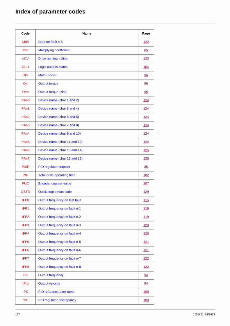
Index of parameter codes
Md8 Date on fault n-8 122
MFr Multiplying coefficient 85
nCV Drive nominal rating 123
OL1r Logic outputs states 104
OPr Motor power 96
Otr Output torque 95
Otrn Output torque (Nm) 95
PAn0 Device name (char 1 and 2) 124
PAn1 Device name (char 3 and 4) 124
PAn2 Device name (char 5 and 6) 124
PAn3 Device name (char 7 and 8) 124
PAn4 Device name (char 9 and 10) 124
PAn5 Device name (char 11 and 12) 124
PAn6 Device name (char 13 and 14) 125
PAn7 Device name (char 15 and 16) 125
PISP PID regulator setpoint 85
PtH Total drive operating time 102
PUC Encoder counter value 107
QSTD Quick stop option code 129
rFP0 Output frequency on last fault 115
rFP1 Output frequency on fault n-1 119
rFP2 Output frequency on fault n-2 119
rFP3 Output frequency on fault n-3 120
rFP4 Output frequency on fault n-4 120
rFP5 Output frequency on fault n-5 121
rFP6 Output frequency on fault n-6 121
rFP7 Output frequency on fault n-7 122
rFP8 Output frequency on fault n-8 122
rFr Output frequency 94
rFrd Output velocity 94
rPC PID reference after ramp 100
rPE PID regulator discrepancy 100
Code Name Page
137 1755861 02/2013

Index of parameter codes
rPF PID regulator feedback reference 100
rPO PID regulator limit output reference 100
rtH Total motor operating time 102
rtP0 Motor operating time on last fault 117
rtP1 Motor operating time on fault n-1 119
rtP2 Motor operating time on fault n-2 119
rtP3 Motor operating time on fault n-3 120
rtP4 Motor operating time on fault n-4 120
rtP5 Motor operating time on fault n-5 121
rtP6 Motor operating time on fault n-6 121
rtP7 Motor operating time on fault n-7 122
rtP8 Motor operating time on fault n-8 122
SCS Save configuration 72
SMAL Velocity max amount 126
SMIL Velocity min amount 126
SPAL Acceleration delta speed 126
SPAt Acceleration delta time 127
SPdL Deceleration delta speed 127
SPdt Deceleration delta time 127
SPFd Setpoint factor denominator 128
SPFn Setpoint factor numerator 128
tAC IGBT alarm time 102
tHb DBR thermal state 101
tHd Drive thermal state 101
tHP0 Motor thermal state on last fault 115
tHP1 Motor thermal state on fault n-1 119
tHP2 Motor thermal state on fault n-2 119
tHP3 Motor thermal state on fault n-3 120
tHP4 Motor thermal state on fault n-4 120
tHP5 Motor thermal state on fault n-5 121
tHP6 Motor thermal state on fault n-6 121
tHP7 Motor thermal state on fault n-7 122
Code Name Page
1755861 02/2013 138

Index of parameter codes
tHP8 Motor thermal state on fault n-8 122
tHr Motor thermal state 101
tIME Time 103
trO Torque reference after ramp 99
trr Torque reference before ramp 99
UCAL Drive line voltage 123
UdP Drive software version 123
ULn Power supply voltage 101
ULP0 Power supply voltage on last fault 115
ULP1 Supply voltage on fault n-1 119
ULP2 Supply voltage on fault n-2 119
ULP3 Supply voltage on fault n-3 120
ULP4 Supply voltage on fault n-4 120
ULP5 Supply voltage on fault n-5 121
ULP6 Supply voltage on fault n-6 121
ULP7 Supply voltage on fault n-7 122
ULP8 Supply voltage on fault n-8 122
UNT Units of parameters APH, PTH, and RTH 96
UOP Motor voltage 96
VAL Load parameter set command 77
Code Name Page
139 1755861 02/2013

ATV71_communication_parameters_EN_1755861_08
1755861 02/2013


![Getting Started With PowerSuite[1]](https://static.fdocuments.net/doc/165x107/544e2bfdb1af9f2f638b4bb1/getting-started-with-powersuite1.jpg)