ATOMIC FORCE MICROSCOPYATOMIC FORCE MICROSCOPY AFPO Group – Laboratoire de physique des solides -...
1
ATOMIC FORCE MICROSCOPY AFPO Group – Laboratoire de physique des solides - CNRS & Universit´ e Paris Sud-11 Bˆ at. 510 - Campus Universitaire 91405 Orsay cedex. Introduction The AFM was invented by Binnig, Quate and Gerber in 1986, and is one of the foremost tools for imaging, measuring and manipulating matter at the nanoscale. The term ’microscope’ in the name is actually a misnomer because it implies looking, while in fact the information is gathered by ”feeling” the surface with a mechanical probe. 1 AFM Basic principles The AFM consists of a microscale cantilever with a sharp tip (probe) at its end that is used to scan the specimen surface. • The cantilever is typically silicon or silicon nitride. • The tip radius of curvature on the order of nanometers. When the tip is brought into proximity of a sample surface, forces between the tip and the sample lead to a deflection of the cantilever. 2 AFM Imaging modes Contact mode It is the most common method of operation of the AFM. The tip and sample remain in close contact as the scanning proceeds. Low stiffness cantilevers are used to boost the deflection signal (0.01-0.5 N/m). Typically the tips are mounted on a triangular cantilever. The force exerted between the tip and the sample in contact mode is on the order of about 0.1-1000n N. Tip-surface controlled by a feedback on the applied force on the tip. One of the drawbacks of remaining in contact with the sample is that there exist large lateral forces on the sample as the drip is ”dragged” over the specimen. Acoustic mode (Tapping mode c ) Technique for imaging soft samples. In AC mode ,the cantilever near its resonant frequency. AC mode AFM can be classified into two categories, intermittent contact mode and non-contact mode, depending on the force regime and the tip-sample separation distance. Negligible lateral forces are encountered. High frequency cantilevers are used to increase the sensibility (200-500 Hz). Typically the tips are mounted on a linear cantilever with a stiffness in the range of (10-100 N/m). The system monitors the resonant frequency or amplitude of the cantilever and keeps it constant by a feedback circuit that moves the scanner up and down. The spatial variation of the change can be presented in height (topography) or interaction (amplitude or phase) images that can be collected simultaneously. As the AFM tip encounters regions of different compo- sition, a change in phase, relative to the phase of the drive signal, is measured and recorded. This change in phase is very sensitive to variations in material properties, including surface stiffness, elasticity and adhesion. The phase shifts are measured and displayed in a very straightforward manner that facilitates quantitative analysis and interpretation. Force Modulation Force Modulation AFM is a fast, very sensitive imaging method that is especially useful to measure and detect variations in a surface’s mechanical properties, including stiffness and elasticity. In this technique, a modulated driving signal at a constant frequency is applied to the AFM cantilever while the AFM tip is in contact with the sample, while amplitude variation and phase lag during the scan are measured. Force modulation provides the user with simultaneous surface topography measurements, material elasticity or stiffness (the amplitude of the modulated signal), and energy dissipation characteristics of the sample (from the phase of the cantilever response). When an AFM cantilever is modulated with the driving signal, elastic materials will result in relatively larger modulated amplitude compared to stiffer materials because the AFM tip can indent an elastic material. Torsion mode 3 Force-distance measurements The AFM tip is approached towards and retracted from the surface and the static deflection of the cantilever is monitored as a function of piezo displacement. These measurements allow: –measure nanoscale contacts, – atomic bonding, van-der-Waals and Casimir forces, – hydration/ solvation forces in liquids – and single molecule stretching and rupture forces. Forces of the order of a few pico-Newton can now be routinely measured with a vertical distance resolution of better than 0.1 nanometer. 4 The different AFM of the group Molecular Imaging PicoLE with a PicoScan controller Technical specifications: – Fixed sample AFM – 100 μm scanner – controlled temperature (ambiant-200 ◦ C) – complete control of imaging environments, including atmosphere, humidity, buffer, and temperature – small samples – easy access to the sample – liquid imaging available. AFM controller: It employs a hybrid feedback servo system with a 32-bit DSP to per- form scans and image acquisition. Five 20-bit DACs provide high- precision X, Y, and Z positioning. A high-speed link is used to trans- fer data between the controller and the computer to ensure error-free communication. Windows R -based PicoScan software is designed for total scan control. Advanced features for spectroscopy, scripting, and post-imaging processing make it the ultimate facility for all SPM ex- periments. Dimension 3100 microscope with a Nanoscope IVa controller Technical specifications: – Fixed sample AFM – 100 μm scanner – large samples up to 200mm in diameter – easy access to the sample – torsion mode available – signal access module – tunneling AFM (TUNA mode) – nanomanipulation and nanolithography software – X, Y closed-loop. AFM Nanoscope IVa controller: – on-board analog feedback loop – lock-In Amplifiers for Dynamic Measurements – six 16-bit A/D converters, four of which are user-available and can be used to input external signals into the NanoScope IVa – easy access to line sync (end of a scan line) and frame sync (end of an image frame) signals so that you can synchronize your external input signal with scan lines and with image frames. Also, the reference signal of the lock-in amplifier is eas- ily accessible. Autoprobe CP with a ParkScientific controller Technical specifications: – Fixed tip AFM scanner – 100 μm scanner – 10 μm scanner – Liquid cell – easy access to the sample – easy observation of the sample – contact & tapping mode – Phase detection. Park controller: – X, Y closed-loop Nanoscope II microscope in AFM and STM mode Technical specifications: – Contact AFM only – Fixed tip AFM/STM – 125 μm AFM scanner (J-scanner) – 0,7 μm AFM scanner (A-scanner) – contact mode. – 0,7 μm STM scanner (A-scanner) Controller: – Nanoscope II emulated by the Nanoscope IVa controller 5 AFM pictures Exemple of a set of AFM pictures in AC-AFM.
Transcript of ATOMIC FORCE MICROSCOPYATOMIC FORCE MICROSCOPY AFPO Group – Laboratoire de physique des solides -...
ATOMIC FORCE MICROSCOPYAFPO Group – Laboratoire de physique des solides - CNRS & Universite Paris Sud-11
Bat. 510 - Campus Universitaire91405 Orsay cedex.
Introduction
The AFM was invented by Binnig, Quate and Gerber in 1986, and is one of the foremost tools for imaging,measuring and manipulating matter at the nanoscale. The term ’microscope’ in the name is actually amisnomer because it implies looking, while in fact the information is gathered by ”feeling” the surfacewith a mechanical probe.
1 AFM Basic principles
The AFM consists of a microscale cantilever with a sharp tip (probe) at its end that is used to scan thespecimen surface.
• The cantilever is typically silicon or silicon nitride.
• The tip radius of curvature on the order of nanometers.
When the tip is brought into proximity of a sample surface, forces between the tip and the sample lead to adeflection of the cantilever.
échantillon
Laser diode
four quadrant photodiode array
24
13
Laser beam
reflected beam
Cantilever tip
boucle d�asservissement
Piezoelectric device
.X Y
Z��yySample
2 AFM Imaging modes
Contact mode
It is the most common method of operation of the AFM. The tip and sample remain in close contact as thescanning proceeds.
Low stiffness cantilevers are used to boost the deflection signal (0.01-0.5 N/m). Typically the tips aremounted on a triangular cantilever. The force exerted between the tip and the sample in contact mode ison the order of about 0.1-1000n N.
Tip-surface controlled by a feedback on the applied force on the tip.
One of the drawbacks of remaining in contact with the sample is that there exist large lateral forces on thesample as the drip is ”dragged” over the specimen.
Acoustic mode (Tapping mode c©)
Technique for imaging soft samples.
In AC mode ,the cantilever near its resonant frequency. AC mode AFM can be classified into twocategories, intermittent contact mode and non-contact mode, depending on the force regime and thetip-sample separation distance.
Negligible lateral forces are encountered.
High frequency cantilevers are used to increase the sensibility (200-500 Hz). Typically the tips are mountedon a linear cantilever with a stiffness in the range of (10-100 N/m).
The system monitors the resonant frequency or amplitude of the cantilever and keeps it constant by afeedback circuit that moves the scanner up and down.
The spatial variation of the change can be presented in height (topography) or interaction (amplitude orphase) images that can be collected simultaneously. As the AFM tip encounters regions of different compo-sition, a change in phase, relative to the phase of the drive signal, is measured and recorded. This changein phase is very sensitive to variations in material properties, including surface stiffness, elasticity andadhesion. The phase shifts are measured and displayed in a very straightforward manner that facilitatesquantitative analysis and interpretation.
Force Modulation
Force Modulation AFM is a fast, very sensitive imaging method that is especially useful to measure anddetect variations in a surface’s mechanical properties, including stiffness and elasticity. In this technique,a modulated driving signal at a constant frequency is applied to the AFM cantilever while the AFM tip isin contact with the sample, while amplitude variation and phase lag during the scan are measured. Forcemodulation provides the user with simultaneous surface topography measurements, material elasticityor stiffness (the amplitude of the modulated signal), and energy dissipation characteristics of the sample(from the phase of the cantilever response). When an AFM cantilever is modulated with the driving signal,elastic materials will result in relatively larger modulated amplitude compared to stiffer materials becausethe AFM tip can indent an elastic material.
Torsion mode
3 Force-distance measurements
The AFM tip is approached towards and retracted from the surface and the static deflection of the cantileveris monitored as a function of piezo displacement.These measurements allow:–measure nanoscale contacts,– atomic bonding, van-der-Waals and Casimir forces,– hydration/ solvation forces in liquids– and single molecule stretching and rupture forces.Forces of the order of a few pico-Newton can now be routinely measured with a vertical distance resolutionof better than 0.1 nanometer.
4 The different AFM of the group
Molecular Imaging PicoLE with a PicoScan controller
Technical specifications:– Fixed sample AFM– 100 µm scanner– controlled temperature (ambiant-200 ◦C)– complete control of imaging environments, including atmosphere,humidity, buffer, and temperature– small samples– easy access to the sample– liquid imaging available.AFM controller:It employs a hybrid feedback servo system with a 32-bit DSP to per-form scans and image acquisition. Five 20-bit DACs provide high-precision X, Y, and Z positioning. A high-speed link is used to trans-fer data between the controller and the computer to ensure error-freecommunication. Windows R©-based PicoScan software is designed fortotal scan control. Advanced features for spectroscopy, scripting, andpost-imaging processing make it the ultimate facility for all SPM ex-periments.
Dimension 3100 microscope with a Nanoscope IVa controller
Technical specifications:– Fixed sample AFM– 100 µm scanner– large samples up to 200mm in diameter– easy access to the sample– torsion mode available– signal access module– tunneling AFM (TUNA mode)– nanomanipulation and nanolithography software– X, Y closed-loop.AFM Nanoscope IVa controller:– on-board analog feedback loop– lock-In Amplifiers for Dynamic Measurements– six 16-bit A/D converters, four of which are user-availableand can be used to input external signals into the NanoScopeIVa– easy access to line sync (end of a scan line) and frame sync(end of an image frame) signals so that you can synchronizeyour external input signal with scan lines and with imageframes. Also, the reference signal of the lock-in amplifier is eas-ily accessible.
Autoprobe CP with a ParkScientific controller
Technical specifications:– Fixed tip AFM scanner– 100 µm scanner– 10 µm scanner– Liquid cell– easy access to the sample– easy observation of the sample– contact & tapping mode– Phase detection.Park controller:– X, Y closed-loop
Nanoscope II microscope in AFM and STM mode
Technical specifications:
– Contact AFM only– Fixed tip AFM/STM– 125 µm AFM scanner (J-scanner)– 0,7 µm AFM scanner (A-scanner)– contact mode.– 0,7 µm STM scanner (A-scanner)
Controller:– Nanoscope II emulated by the Nanoscope IVa controller
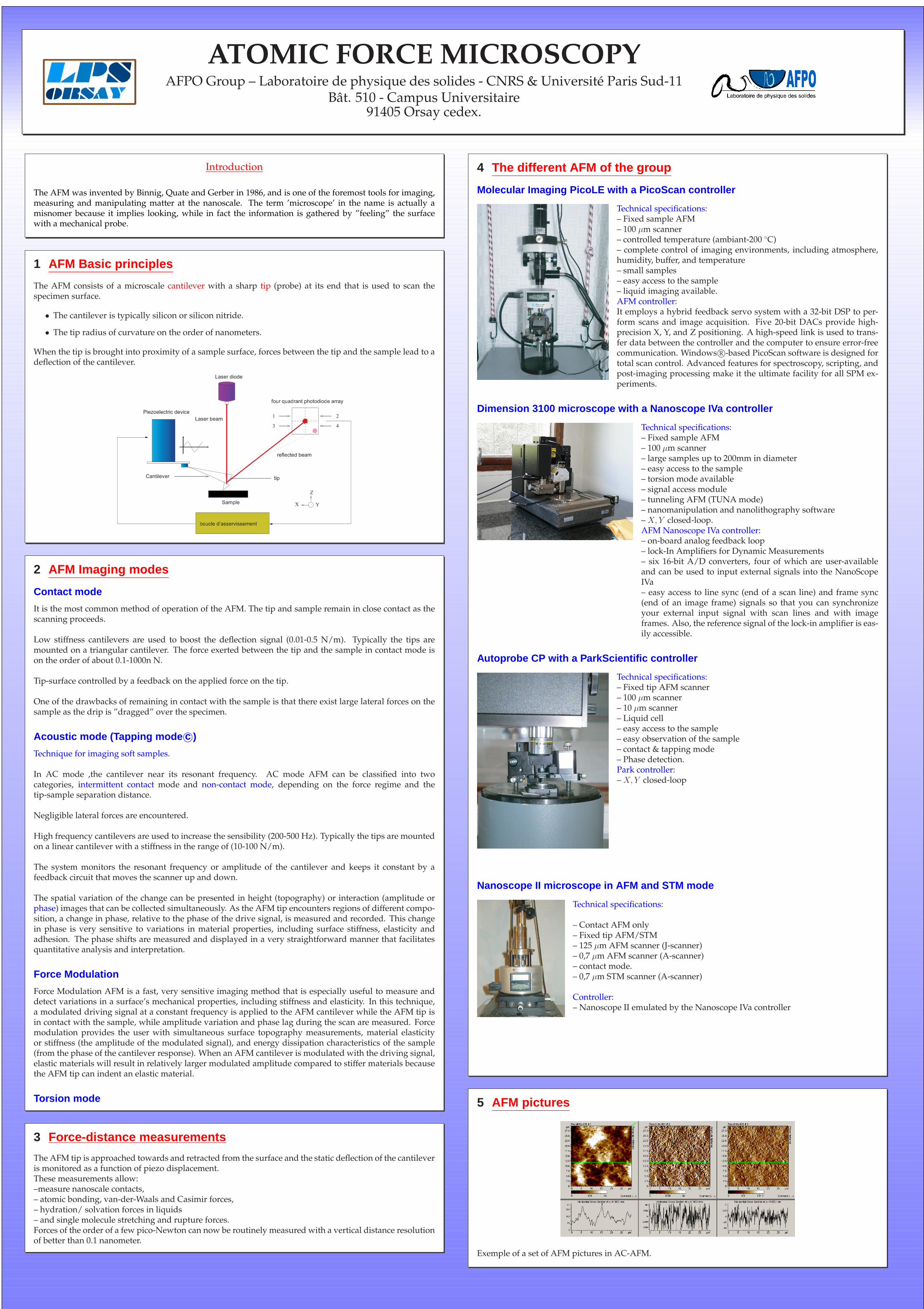
5 AFM pictures
Exemple of a set of AFM pictures in AC-AFM.