Atom Interferometric Gravity Wave Detectors
25
Atom Interferometric Gravity Wave Detectors Mark Kasevich Dept. of Physics and Applied Physics Stanford University, Stanford CA
Transcript of Atom Interferometric Gravity Wave Detectors
Atom InterferometricGravity Wave Detectors
Mark KasevichDept. of Physics and Applied Physics
Stanford University, Stanford CA
Outline
• Basic concepts• Current instrumentation• AGIS detectors
– Space-based/LEO– Terrestrial– Systematics
• Status of instrument development
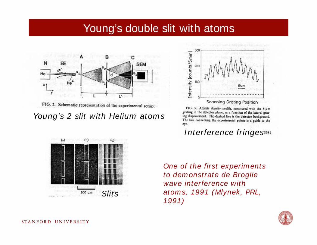
Young’s double slit with atoms
Young’s 2 slit with Helium atoms
Slits
Interference fringes
One of the first experiments to demonstrate de Broglie wave interference with atoms, 1991 (Mlynek, PRL, 1991)
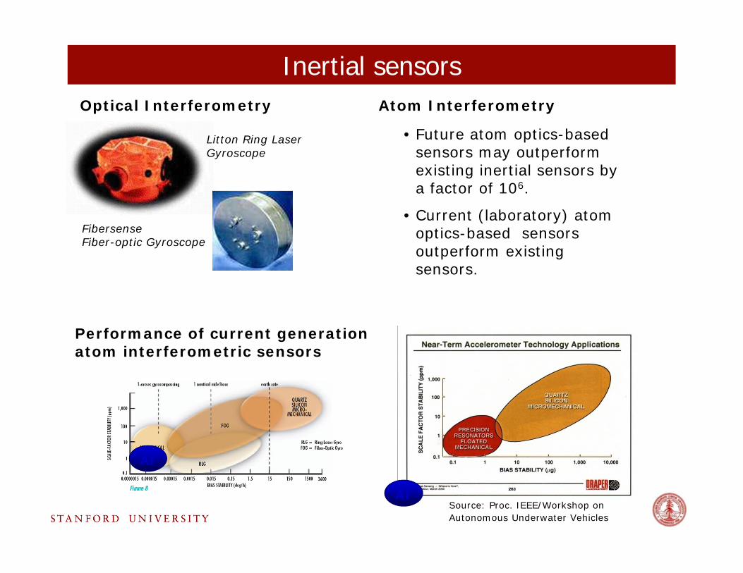
Inertial sensors
• Future atom optics-based sensors may outperform existing inertial sensors by a factor of 106.
• Current (laboratory) atom optics-based sensors outperform existing sensors.
Optical Interferometry Atom Interferometry
Litton Ring Laser Gyroscope
Fibersense Fiber-optic Gyroscope
AI
AI
Performance of current generation atom interferometric sensors
Source: Proc. IEEE/Workshop on Autonomous Underwater Vehicles
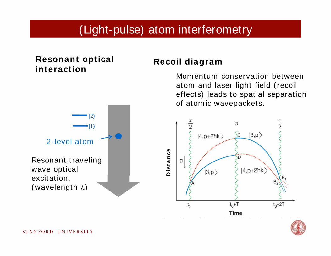
Resonant traveling wave optical excitation, (wavelength )
(Light-pulse) atom interferometry
2-level atom
|2
|1
Resonant optical interaction
Recoil diagramMomentum conservation between atom and laser light field (recoil effects) leads to spatial separation of atomic wavepackets.
Dis
tan
ce
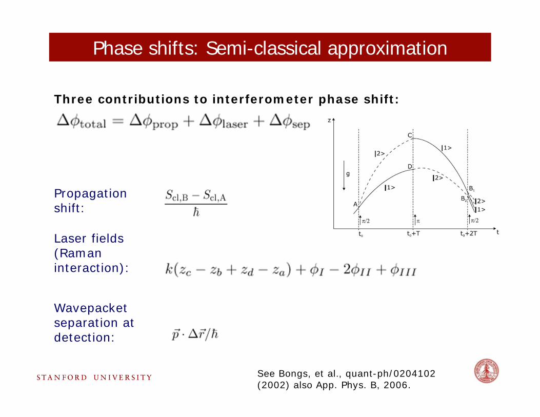
Phase shifts: Semi-classical approximation
Three contributions to interferometer phase shift:
Propagation shift:
Laser fields (Raman interaction):
Wavepacket separation at detection:
See Bongs, et al., quant-ph/0204102 (2002) also App. Phys. B, 2006.
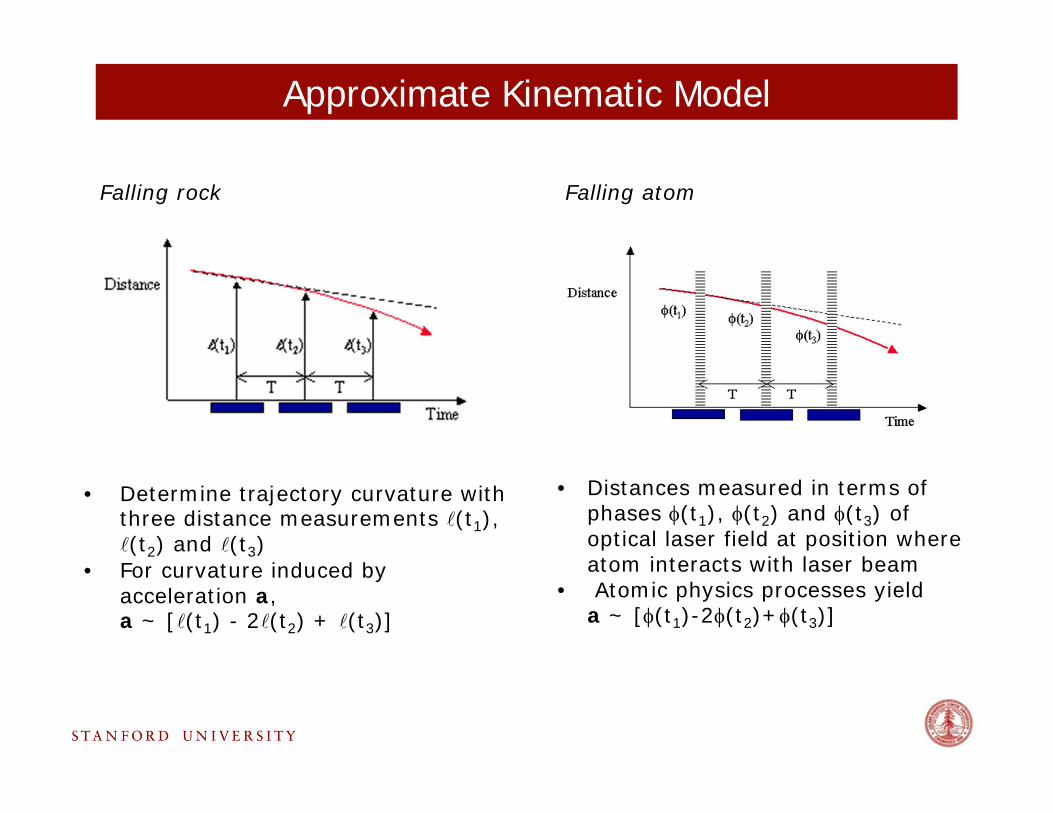
Falling rock Falling atom
• Distances measured in terms of phases (t1), (t2) and (t3) of optical laser field at position where atom interacts with laser beam
• Atomic physics processes yield a ~ [(t1)-2(t2)+(t3)]
• Determine trajectory curvature with three distance measurements (t1), (t2) and (t3)
• For curvature induced by acceleration a, a ~ [(t1) - 2(t2) + (t3)]
Approximate Kinematic Model
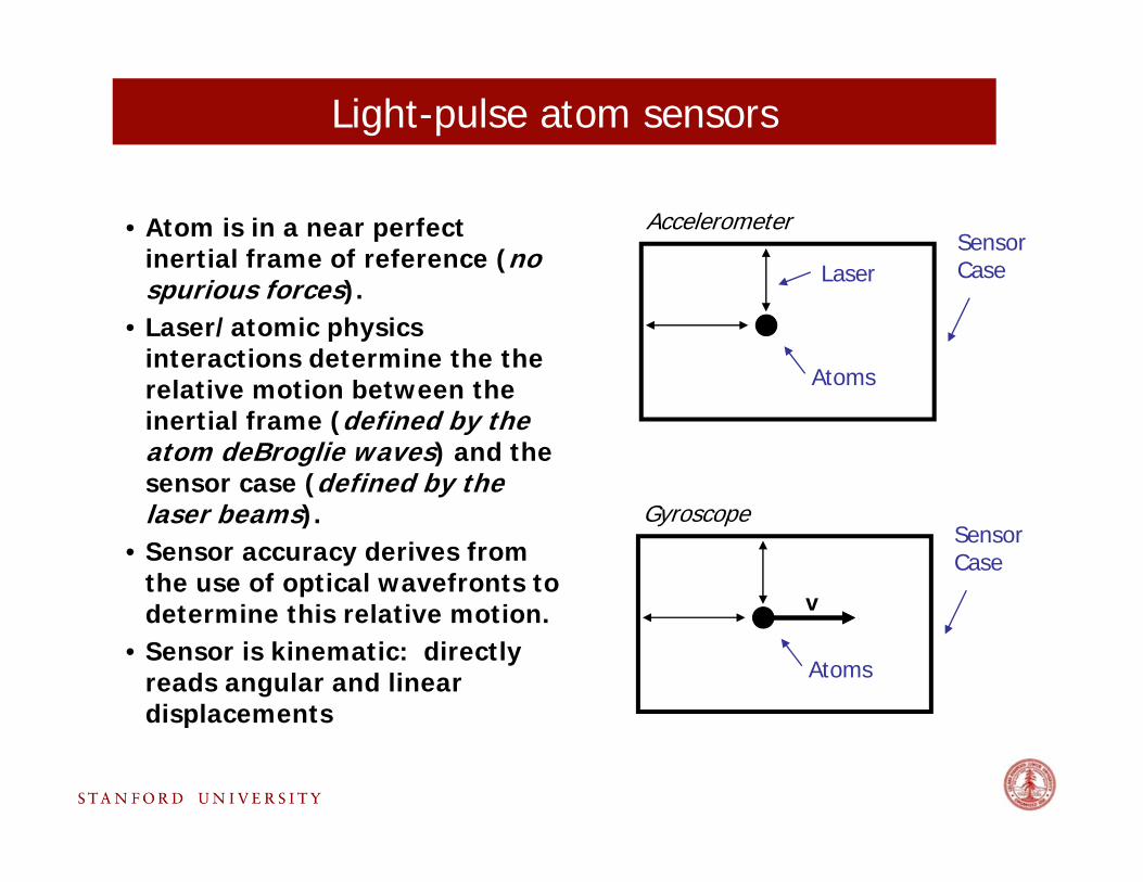
Light-pulse atom sensors
• Atom is in a near perfect inertial frame of reference (no spurious forces).
• Laser/atomic physics interactions determine the the relative motion between the inertial frame (defined by the atom deBroglie waves) and the sensor case (defined by the laser beams).
• Sensor accuracy derives from the use of optical wavefronts to determine this relative motion.
• Sensor is kinematic: directly reads angular and linear displacements
Sensor Case
Atoms
Accelerometer
Sensor Case
Atoms
Gyroscope
v
Laser
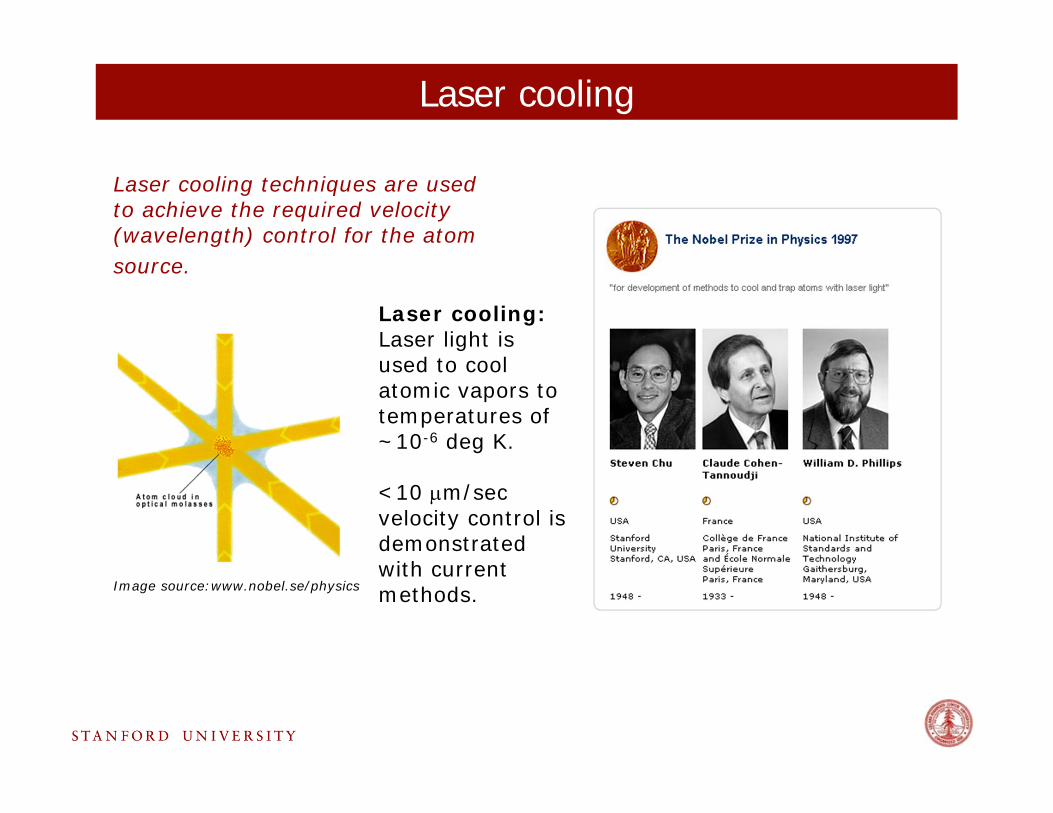
Laser cooling
Laser cooling techniques are used to achieve the required velocity (wavelength) control for the atom source.
Laser cooling:Laser light is used to cool atomic vapors to temperatures of ~10-6 deg K.
<10 m/sec velocity control is demonstrated with current methods.Image source:www.nobel.se/physics
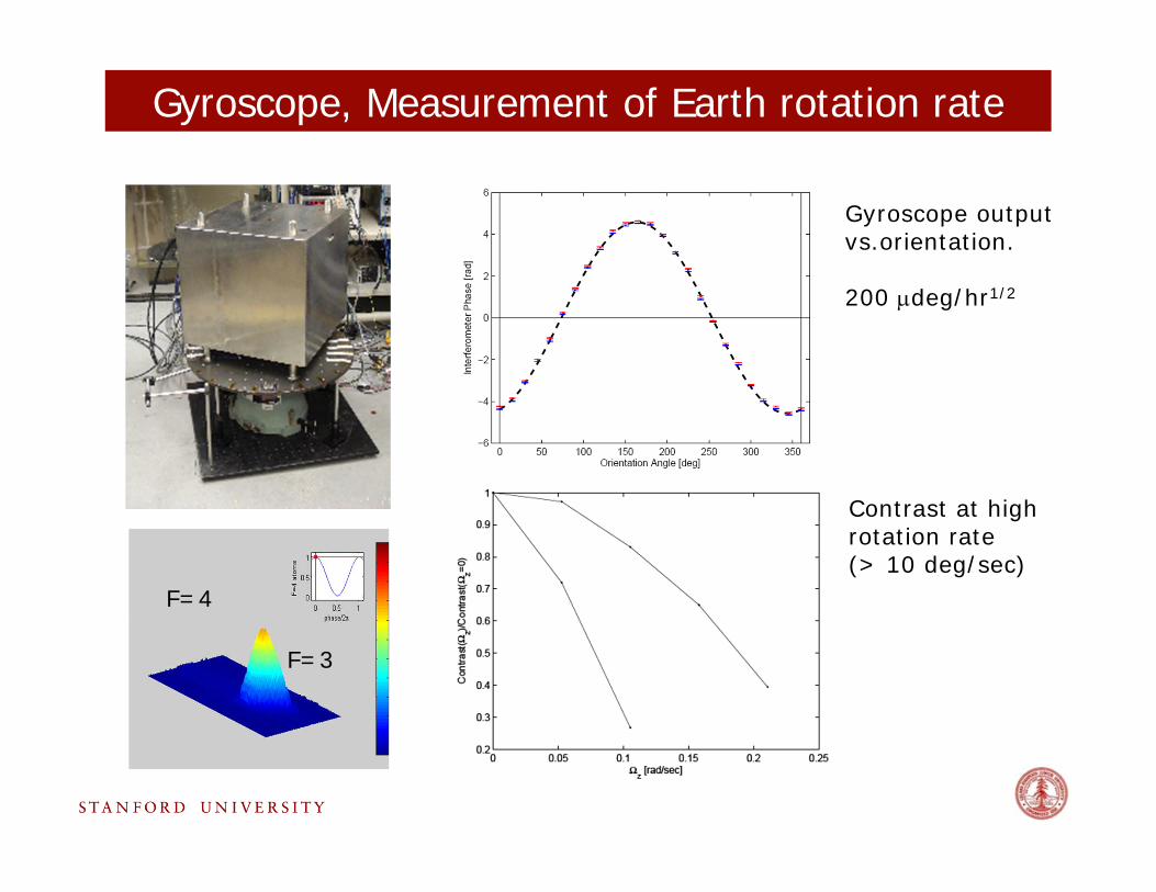
Gyroscope, Measurement of Earth rotation rate
Gyroscope output vs.orientation.
200 deg/hr1/2
Interior view F=3
F=4
Contrast at high rotation rate (> 10 deg/sec)
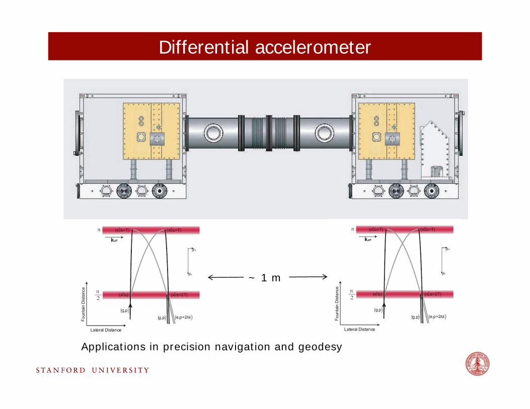
Differential accelerometer
Applications in precision navigation and geodesy
~ 1 m
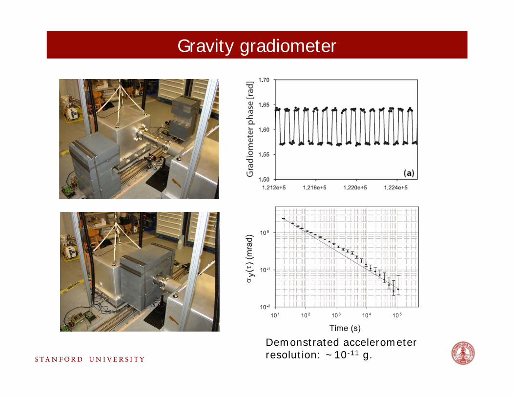
Gravity gradiometer
Demonstrated accelerometer resolution: ~10-11 g.
atom
laser
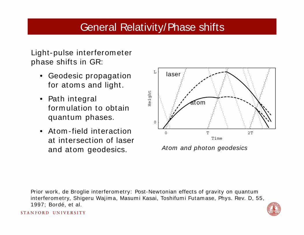
General Relativity/Phase shifts
Light-pulse interferometer phase shifts in GR:
• Geodesic propagation for atoms and light.
• Path integral formulation to obtain quantum phases.
• Atom-field interaction at intersection of laser and atom geodesics.
Prior work, de Broglie interferometry: Post-Newtonian effects of gravity on quantum interferometry, Shigeru Wajima, Masumi Kasai, Toshifumi Futamase, Phys. Rev. D, 55, 1997; Bordé, et al.
Atom and photon geodesics
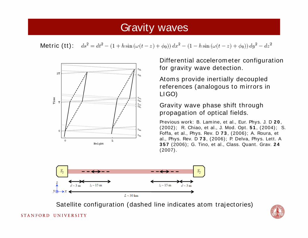
Gravity wavesMetric (tt):
Differential accelerometer configuration for gravity wave detection.
Atoms provide inertially decoupled references (analogous to mirrors in LIGO)
Gravity wave phase shift through propagation of optical fields.Previous work: B. Lamine, et al., Eur. Phys. J. D 20, (2002); R. Chiao, et al., J. Mod. Opt. 51, (2004); S. Foffa, et al., Phys. Rev. D 73, (2006); A. Roura, et al., Phys. Rev. D 73, (2006); P. Delva, Phys. Lett. A 357 (2006); G. Tino, et al., Class. Quant. Grav. 24 (2007).
Satellite configuration (dashed line indicates atom trajectories)
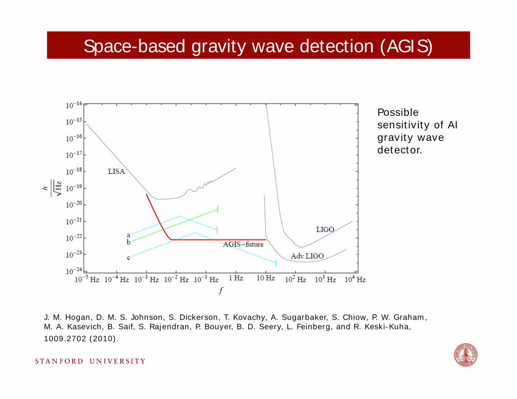
Space-based gravity wave detection (AGIS)
J. M. Hogan, D. M. S. Johnson, S. Dickerson, T. Kovachy, A. Sugarbaker, S. Chiow, P. W. Graham, M. A. Kasevich, B. Saif, S. Rajendran, P. Bouyer, B. D. Seery, L. Feinberg, and R. Keski-Kuha, 1009.2702 (2010).
Possible sensitivity of AI gravity wave detector.
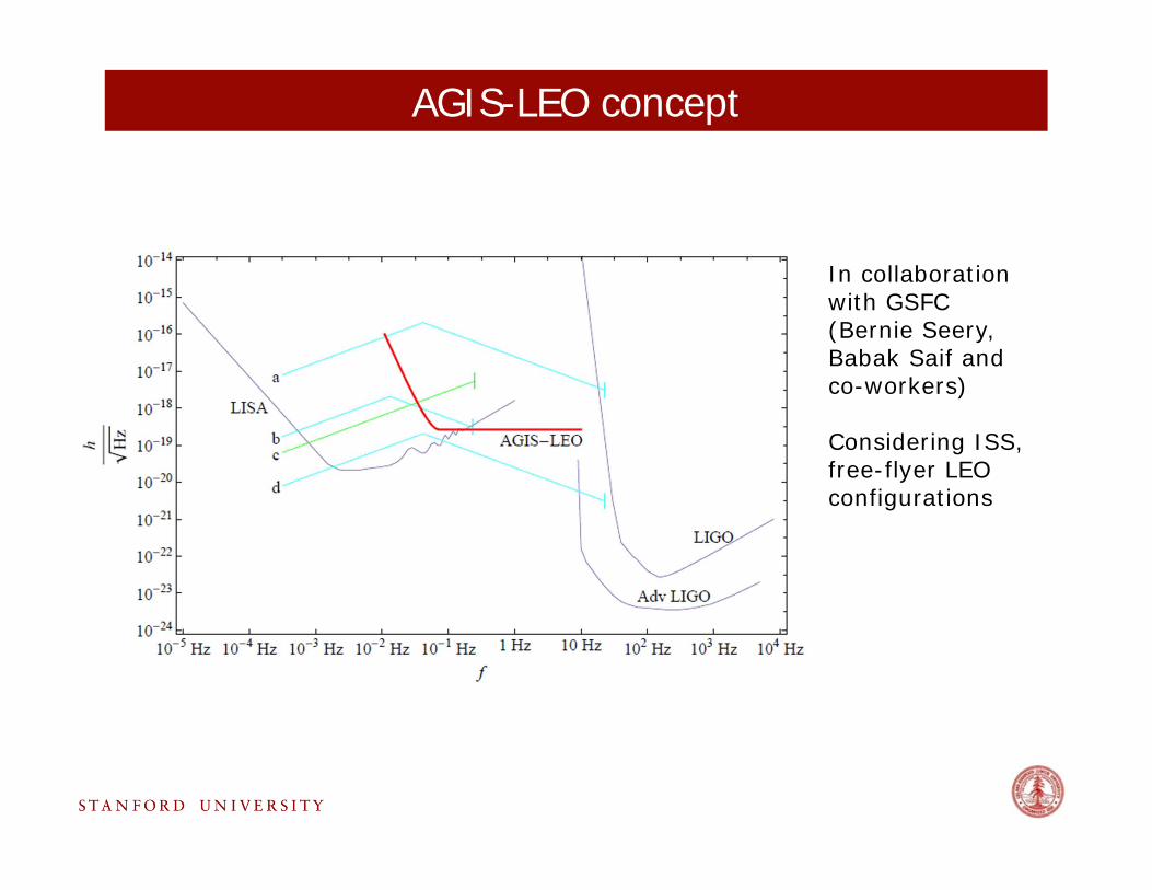
AGIS-LEO concept
In collaboration with GSFC (Bernie Seery, Babak Saif and co-workers)
Considering ISS, free-flyer LEO configurations
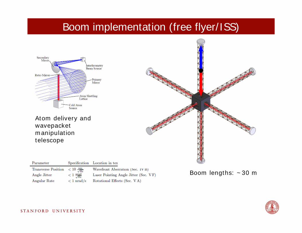
Boom implementation (free flyer/ISS)
Boom lengths: ~30 m
Atom delivery and wavepacketmanipulation telescope
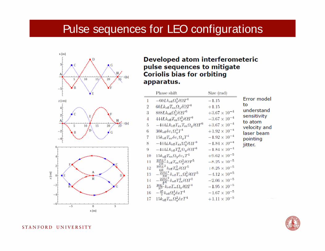
Pulse sequences for LEO configurations
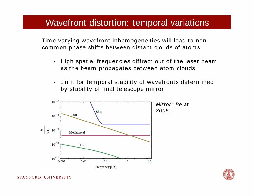
Wavefront distortion: temporal variations
Time varying wavefront inhomogeneities will lead to non-common phase shifts between distant clouds of atoms
- High spatial frequencies diffract out of the laser beam as the beam propagates between atom clouds
- Limit for temporal stability of wavefronts determined by stability of final telescope mirror
Mirror: Be at 300K
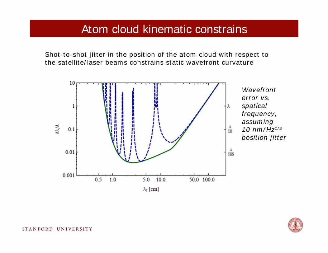
Atom cloud kinematic constrains
Shot-to-shot jitter in the position of the atom cloud with respect to the satellite/laser beams constrains static wavefront curvature
Wavefronterror vs. spaticalfrequency, assuming 10 nm/Hz1/2
position jitter
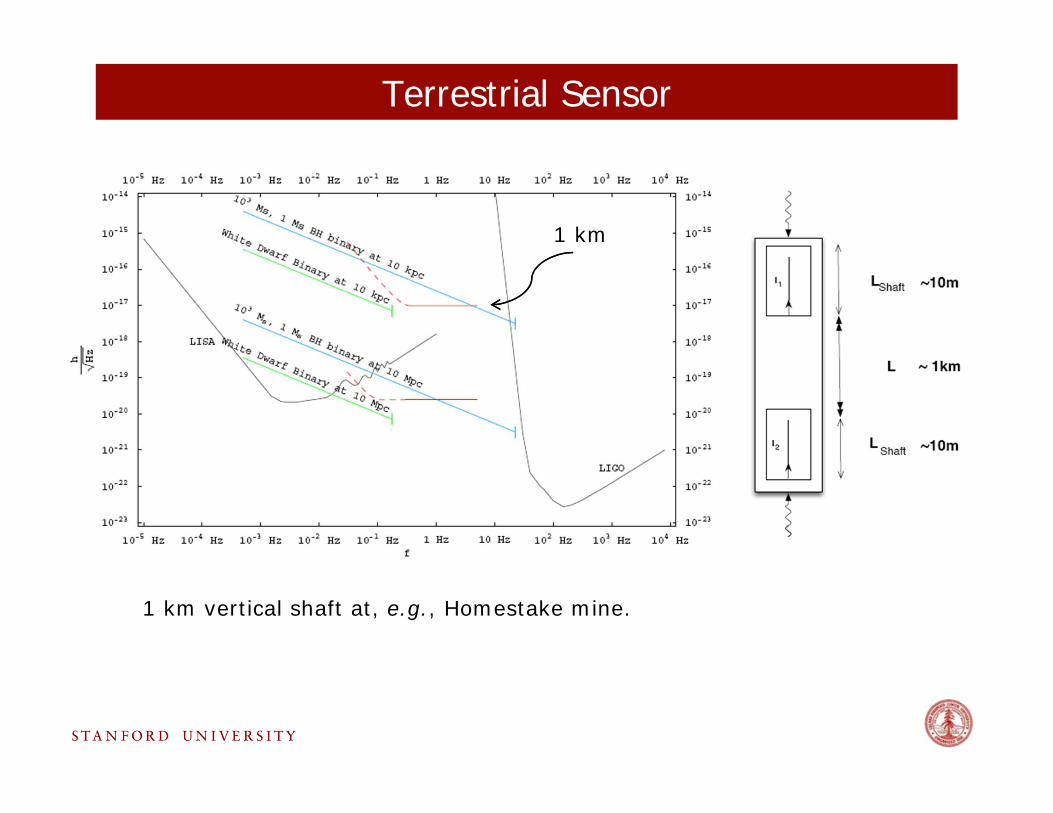
Terrestrial Sensor
1 km vertical shaft at, e.g., Homestake mine.
1 km
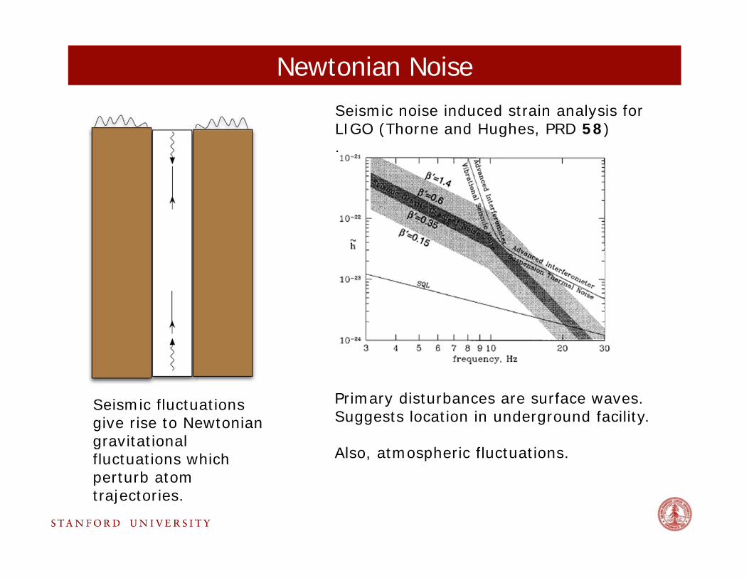
Newtonian NoiseSeismic noise induced strain analysis for LIGO (Thorne and Hughes, PRD 58).
Seismic fluctuations give rise to Newtonian gravitational fluctuations which perturb atom trajectories.
Primary disturbances are surface waves. Suggests location in underground facility.
Also, atmospheric fluctuations.
References
Satellite/LEO;Full analysis of wavefronterrors
J. M. Hogan, D. M. S. Johnson, S. Dickerson, T. Kovachy, A. Sugarbaker, S. Chiow, P. W. Graham, M. A. Kasevich, B. Saif, S. Rajendran, P. Bouyer, B. D. Seery, L. Feinberg, and R. Keski-Kuha, 1009.2702 (2010).
Satellite;Terrestrial
S. Dimopoulos, P. W. Graham, J. M. Hogan, M. A. Kasevich, and S. Rajendran, Phys. Rev. D 78, 122002 (2008).
GeneralRelativity using Atom Interferometers
S. Dimopoulos, P. W. Graham, J. M. Hogan, and M. A. Kasevich, Phys. Rev. D 78, 042003 (2008).
References analyzing GW detection using AI
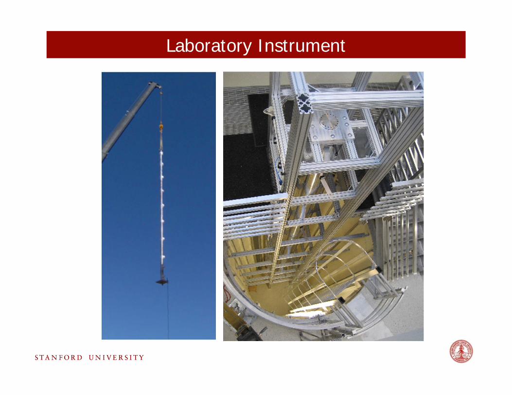
Laboratory Instrument
Acknowledgements
– Grant Biedermann, PhD, Physics– Ken Takase, PhD, Physics– John Stockton, Post-doctoral fellow– Louis Delsauliers, Post-doctoral fellow– Xinan Wu, Graduate student, Applied physics– Chetan Mahadeswaraswamy, Graduate student, Mechanical engineering– David Johnson, Graduate student, Physics– Jason Hogan, Post-doctoral fellow, Physics– Hui-Chun Chien, Graduate student, Physics– Sean Roy, Graduate student, Physics– Tim Kovachy, Graduate student, Physics– Alex Sugarbaker, Graduate student, Physics– Susannah Dickerson, Graduate student, Physics– Sheng-wei Chiow, Post-doctoral fellow, Physics
+ THEORY COLLABORATORS: S. Dimopolous, P. Graham, S. Rajendran, A. Arvanitaki, A. Geraci
+ GSFC COLLABORATORS:B. Saif, B. Seery, L. Feinberg, R. Keski-Kuha
+ AOSENSE TEAM