Assessment of Hydrocarbon Explosion and Fire Risks Professor Jeom Paik · Assessment of Hydrocarbon...
33
1 Assessment of Hydrocarbon Explosion and Fire Risks by Professor Jeom Paik The LRET Research Collegium Southampton, 11 July – 2 September 2011
Transcript of Assessment of Hydrocarbon Explosion and Fire Risks Professor Jeom Paik · Assessment of Hydrocarbon...

1
Assessment of Hydrocarbon Explosion and Fire Risks
by
Professor Jeom Paik
The LRET Research CollegiumSouthampton, 11 July – 2 September 2011

Assessment of Hydrocarbon Explosion and Fire Risksin Offshore Installations:
Recent Advances and Future Trends
Prof. Jeom Kee Paik, DirectorThe LRET Research Center of Excellence
at Pusan National University, Korea

New Paradigm for Robust Design of Ships and Offshore …
Design Formula
Experimental InvestigationExperimental Investigation
Past Experience First PrinciplesFirst Principles
Deterministic ProbabilisticProbabilistic
Mathematical Algorithm
( )21 1
!lim! !
m n
xi j
nr n rx x
ζφαβγε η→∞
= = −− +∑∑
Limit States/RiskLimit States/RiskAllowable Stress
EngineeringEngineering
Various Ocean Environmental Phenomena
Traditional Future

Trend in Offshore Oil & Gas Production Systems• Fixed type in shallow waters Floating type in deep waters• Ship-shaped offshore unit, Semi-sub, Spar, TLP• Pipeline infrastructure Multiple functions such as
production, storage and offloading

Vessel (hull), topsides (process facility), mooring, risers/flow lines, subsea, and export system
FPSO for Oil and Gas Production

Oil/Gas Leak Resulting in Explosion and Fire
Source: HSE
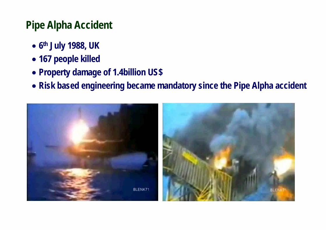
• 6th July 1988, UK• 167 people killed• Property damage of 1.4billion US$• Risk based engineering became mandatory since the Pipe Alpha accident
Pipe Alpha Accident

• 20th April 2010, Gulf of Mexico• 11 people killed, 17 people wounded• Environmental damage of approx. 30 billion US$
Deepwater Horizon Accident
Oil spill

• Hydrocarbons can explode through ignition when combined with an oxidiser (usually air). Thus, when the temperature rises to the pointat which hydrocarbon molecules react spontaneously to an oxidiser,combustion takes place. This hydrocarbon explosion causes a blastand a rapid increase in overpressure.• Fire is a combustible vapour or gas that combines with an oxidiser in a combustion process that is manifested by the evolution of light, heat,and flame.• The impact of overpressure from explosions and that of elevatedtemperature from fire are the primary concern in terms of the actions thatresult from hazards within the risk assessment and managementframework.
Hydrocarbon Explosions and Fires
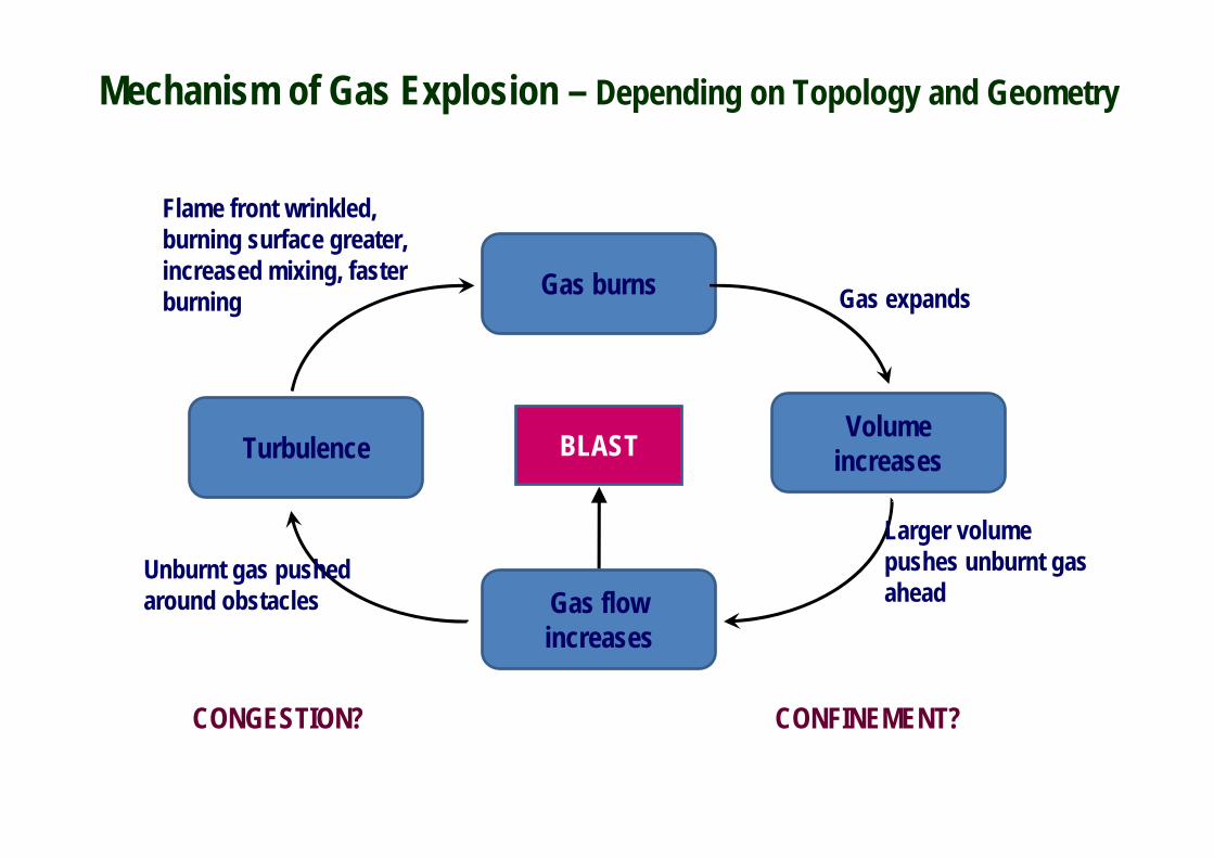
Gas burns
Volume increases
Gas flow increases
Turbulence
Gas expands
Larger volume pushes unburnt gas ahead
Unburnt gas pushed around obstacles
Flame front wrinkled, burning surface greater, increased mixing, faster burning
BLAST
CONGESTION? CONFINEMENT?
Mechanism of Gas Explosion – Depending on Topology and Geometry

Factors Affecting Explosions and Fires
· Wind direction· Wind speed· Leak rate· Leak direction· Leak duration· Leak position (x)· Leak position (y)· Leak position (z)· Type of oil or gas (molecules)· Concentration ratio· Temperature of oil or gas(LNG Cryogenic -163 degree C)

Risk Based Design Process
Hazard identification (Step1)
Riskassessment (Step2)
Decision makingrecommendations (Step5)
Risk control options (Step3)
Cost benefit assessment (Step4)

What is Risk? How to Manage Risk?
i ii
R F C= ×∑• Asset risk
- Damage to structures and equipment- Duration of production delay (downtime)
• Environmental risk- Amount of oil that spills out of the offshore installation
• Personnel risk- Loss of life

Trends in Risk Assessment
Qualitative Quantitative
Past Experience Simulation
Experiment,
Deterministic Probabilistic
Specific Scenarios All Possible Scenarios

API Procedure for Risk-based Design
Doesthe facility
meet screeningcriteria?
Establish performancecriteria
Implement measures toreduce fire and blast risk
Arenominal load cases
applicable?
Assess impact on safetycritical elements
Areperformancecriteria met?
Assessment completefor the facility
Consider fire and blast riskEvent-by-Event
Risk matrix
Reconsideror modify concept
or reassess risk withmore rigorous
approach
Modify or select newconcept or reassess risk
Implement measures toreduce fire and blast risk
Risk matrix
Assess load andresponse for the event
Areperformancecriteria met?
Are furtherrisk reduction options
available?
Assessment completefor the event
Assessment completeensure good practice
Redesign
Yes
No
Yes
No
Yes
Yes
No
Low
Low
Yes
No
NoYes
Medium or Higher
Medium or Higher
Method 1Design
according toguidances is
sufficient if lowconsequencesare expected
Method 2Possibility to
omit load assessmentin certain cases
Method 3Scenario based
load andconsequenceassessment

Simulation-based Procedure for Risk-based Design
Dead and live loads Nominal loads Design guidance
System description
Definition of scenarios
Loads assessment
Design load
Consequence Frequency
Risk evaluation
Risk acceptable Risk unacceptable
Design complete
Mitigation
Redesign
Performanceacceptance
criteria
Riskacceptance
criteria
A
B
A: Limit states based designB: Risk based design
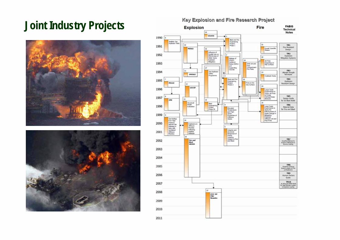
Joint Industry Projects

EFEF JIP - 27th JIP in the WorldExplosion and Fire Engineering of FPSOs
Coordinators:- Pusan National University, Korea- Nowatec AS, Norway
Partners:- DSME, SHI, HHI, ABS, KR, LR- Gexcon, CompuIT, USFOS, UK HSE, NTUA

Quantitative Gas Explosion Risk Assessment and Management (1/2)

Selection of credible scenarios involving PDF parameters of
leak and environment conditions
Selection of credible scenarios involving PDF parameters of
gas cloud conditionE
xplo
sion
freq
uenc
y of
exc
ceda
nce
(per
FPS
O y
ear)
Overpressure (MPa)0 0.02 0.04 0.06 0.08 0.1
0.00001
0.0001
0.001
0.01Large cylindrical vessels (Point 171 )
CAD modelCFD model
Gas dispersion analysis
Explosion CFD simulation Design loads with exceedance curve Nonlinear consequenceanalysis under explosion
EFEF JIP Procedure for Explosion Risk Assessment and Management (2/2)
Latin hypercube sampling technique

EFEF JIP Fire Risk Assessment and Management (1/2)

Selection of credible scenarios involving PDF parameters of
leak and environment conditions
EFEF JIP Procedure for Fire Risk Assessment and Management (2/2)
CAD modelCFD model
Fire CFD simulationDesign loads with exceedance curve
Nonlinear consequenceanalysis under fire
Temperature(K)
Exc
eeda
nce
fire
freq
uenc
y(pe
rFP
SO y
ear)
200 400 600 800 1000 1200
0.00001
0.0001
0.001
0.01
0.1
Mean temperature (Point20 and Point31)
Mean temperature (Point41 and Point52)
Latin hypercube sampling technique

Applied Example: VLCC Class FPSO Topsides

Effect of Gas Cloud Volume on Maximum Overpressure – Comparison between EFEF JIPand Existing FPSO Practices
Ove
rpre
ssur
e (M
Pa)
Equivalent volume (m3)0 2000 4000 6000 8000 10000 12000
0
0.05
0.1
0.15
0.2
0.25
0.3
0.35
0.4
0.45
FPSO AFPSO B
EFEF JIP

Exp
losi
on fr
eque
ncy
of e
xcee
danc
e(p
er F
PSO
yea
r)
Overpressure (MPa)0 0.02 0.04 0.06 0.08 0.1 0.12
0.00001
0.0001
0.001
0.01
Top process deck(Point 226 & 274)
Solid process deck(Point 76 & 124)
Above the middle process deck(Point 161)
Process decks
Design Explosion Loads with Exceedance Curves

0 0.02 0.04 0.06 0.08 0.10 0.12 0.14
0
0.02
0.04
0.06
0.08
0. 10
0.12
0.14R
isk
acce
pted
load
FPSO
C, D
(MPa
)
Risk accepted loadEFEF JIP (MPa)
EFEF JIP vs. FPSO CEFEF JIP vs. FPSO D
Design Explosion Loads – Comparison between EFEF JIP and Existing FPSO Practices
Temperature(K)
Exc
eeda
nce
fire
freq
uenc
y(pe
rFP
SO y
ear)
280 300 320 340 360 380
0.0001
0.001
0.01
0.1
0.00001
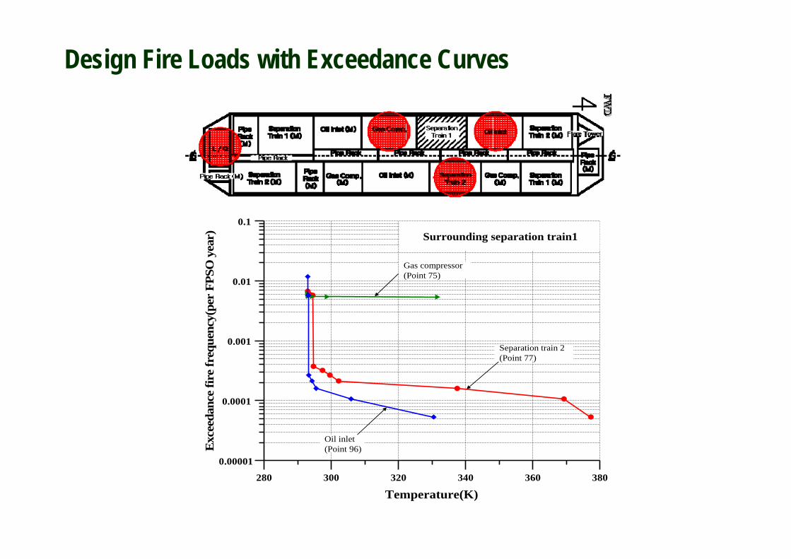
Separation train 2(Point 77)
Oil inlet(Point 96)
Gas compressor(Point 75)
Surrounding separation train1
Design Fire Loads with Exceedance Curves

Nonlinear Structural Consequence Analysis – Escape Route

Trends in Risk Assessment
Qualitative Quantitative
Past Experience Simulation
Experiment
Deterministic Probabilistic
Specific Scenarios All Possible Scenarios

CFD Explosion Simulations
(barg)

Gas Explosion Tests with or without Water Sprays (1/2)- Importance of Risk Management
Source: © The Steel Construction Institute, Fire and Blast Information Group
Without water sprays With water sprays

0.0
2.0
1.5
1.0
0.5
700100 200 300 400 500 600
Time (ms)
TNO PI-10, Test 10, LDN NozzlesTNO PI-10, Test 11, MV57 NozzlesTNO PI-10, Test 12, No Deluge
Source: © The Steel Construction Institute, Fire and Blast Information Group
Gas Explosion Tests with or without Water Sprays (2/2)- Importance of Risk Management

Explosion and Fire Test Facilities under Construction in Korea


![NJP_Reader_1_Nam June Paik ArtCenter [en]](https://static.fdocuments.net/doc/165x107/577d22961a28ab4e1e97cfb4/njpreader1nam-june-paik-artcenter-en.jpg)