SM15K Master/Slave Assembly Kits - Delta-Elektronika.nl · 0&
2012
ASSEMBLY INSTRUCTION ALEX Assembly instructions are designed to provide a description of the assembly
of Delta ALEX.
Delta ALEX is type approved for load class up to class 5
Delta ALEX is designed to create a secure temporary access to installations
and projects where appropriate.
We hope everyone will use this manual to ensure proper installation of
scaffolding. The purpose is to prevent accidents and make the workplace
safe.
Contents
Preface 3
Technical terms/Terminology 4
Material description/Properties 5
General load classification 6
Classification according NS-EN 12811 6
List of components 7
Recommended scaffold widths 15
Permissible load on standards 16
Permissible building height 22
General conditions 23
Inspection and maintenance 24
Bracing 26
Fastening 27
Brackets 27
Anti-falling 28
Scaffold system 29
Mobile scaffolds 35
Stair tower 40
Stairway 43
Base board 45
Bracket 1,2m (SK 1,2) 47
Bracket 0,7m (SK 0,72) 48
Bracket 0,5m (SK 0,5) 49
Bracket 0,3m (SK 0,3) 50
Beam riders (BRM/BRL) 51
Scaffold pulley 52
Hatch panel 1.2x0.6m(LP 1,2) 53
Plank riders 54
DS/EB Diagonal Telescope 55
Assembling of Hanging Scaffold 56 2
Preface
The following rigging instructions are meant as a guide for ALL scaffolders and users of Delta Spirstillas scaffold systems.
When using a new scaffold system, it is important to learn how the scaffold should be erected and which loads the scaffold is designed for. The rigging instructions explain all the important aspects in this context.
Delta Spirstillas is approved for Class 5 loads (450 kg/m2). Special calculations must be performed for greater loads. These calculations can be performed by the supplier.
Many components are available for a variety of applications. We have presented options within the framework that prevails for Class 5 loads. We suggest that you familiarize yourself with the tables presented. These are meant as a useful tool for proper erection of the scaffold.
The scaffold can be combined with various types of steel scaffold systems. In this connection, we ask you to pay special attention to the section on maintenance.
Delta Spirstillas is part of three compatible scaffold systems from the same supplier. You can obtain the same scaffold in steel - "STEELEX" or as a framework scaffold - "RAMEX." A number of additional components are also available. A list of these will be supplied upon request.
We sincerely hope that everyone will follow these instructions to ensure proper erection of the scaffold thus helping prevent accidents and increase job safety.
G O O D L U C K !
3
Technical terms /
Terminology
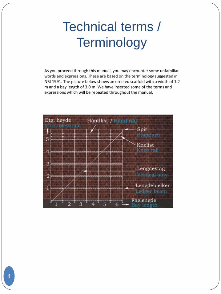
As you proceed through this manual, you may encounter some unfamiliar words and expressions. These are based on the terminology suggested in NBI 1991. The picture below shows an erected scaffold with a width of 1.2 m and a bay length of 3.0 m. We have inserted some of the terms and expressions which will be repeated throughout the manual.
4
Material Description -
Properties
The scaffold is constructed of aluminium, with the exception of certain components that are more adequate in steel. The aluminium alloy is of the Al-Mg-Si-Mn type, which is sea-water resistant.
The alloy can be delivered with certificates from DET NORSKE VERITAS, LLOYDS Register of Shipping or GERMANISHER Lloyd. The alloy elements provide the following material properties:
Mg (magnesium)
Increases strength
Increases hardness
Good corrosion resistance
Improved weld ability
AL + Si (silicon)
Yields temperable alloys in combination with magnesium
Good corrosion resistance
Mn (manganese)
Excellent yielding properties
Increases breaking strength
Good corrosion resistance
Allows for compliance with very small tolerances
As will be apparent from the above, this is an excellent alloy, especially for offshore applications. We have evaluated various types of aluminium alloys, and have selected the alloy recommended by aluminium experts.
5
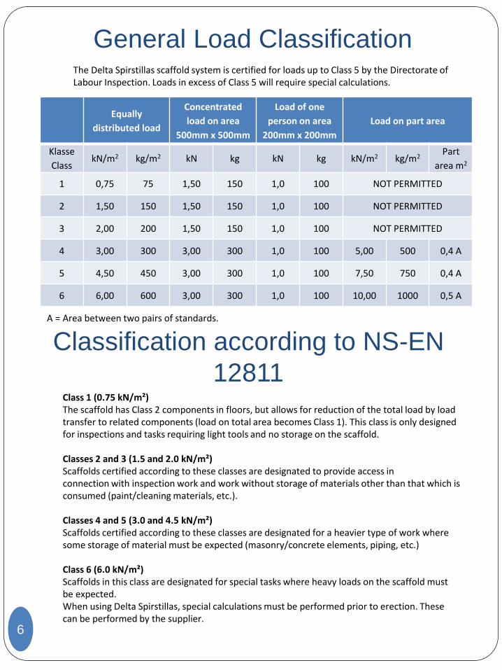
General Load Classification The Delta Spirstillas scaffold system is certified for loads up to Class 5 by the Directorate of Labour Inspection. Loads in excess of Class 5 will require special calculations.
6
Equally
distributed load
Concentrated
load on area
500mm x 500mm
Load of one
person on area
200mm x 200mm
Load on part area
Klasse
Class kN/m2 kg/m2 kN kg kN kg kN/m2 kg/m2
Part
area m2
1 0,75 75 1,50 150 1,0 100 NOT PERMITTED
2 1,50 150 1,50 150 1,0 100 NOT PERMITTED
3 2,00 200 1,50 150 1,0 100 NOT PERMITTED
4 3,00 300 3,00 300 1,0 100 5,00 500 0,4 A
5 4,50 450 3,00 300 1,0 100 7,50 750 0,4 A
6 6,00 600 3,00 300 1,0 100 10,00 1000 0,5 A
A = Area between two pairs of standards.
Class 1 (0.75 kN/m²) The scaffold has Class 2 components in floors, but allows for reduction of the total load by load transfer to related components (load on total area becomes Class 1). This class is only designed for inspections and tasks requiring light tools and no storage on the scaffold. Classes 2 and 3 (1.5 and 2.0 kN/m²) Scaffolds certified according to these classes are designated to provide access in connection with inspection work and work without storage of materials other than that which is consumed (paint/cleaning materials, etc.). Classes 4 and 5 (3.0 and 4.5 kN/m²) Scaffolds certified according to these classes are designated for a heavier type of work where some storage of material must be expected (masonry/concrete elements, piping, etc.) Class 6 (6.0 kN/m²) Scaffolds in this class are designated for special tasks where heavy loads on the scaffold must be expected. When using Delta Spirstillas, special calculations must be performed prior to erection. These can be performed by the supplier.
Classification according to NS-EN
12811
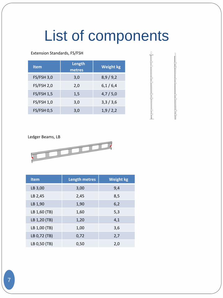
List of components Extension Standards, FS/FSH
7
Item Length
metres Weight kg
FS/FSH 3,0 3,0 8,9 / 9,2
FS/FSH 2,0 2,0 6,1 / 6,4
FS/FSH 1,5 1,5 4,7 / 5,0
FS/FSH 1,0 3,0 3,3 / 3,6
FS/FSH 0,5 3,0 1,9 / 2,2
Ledger Beams, LB
Item Length metres Weight kg
LB 3,00 3,00 9,4
LB 2,45 2,45 8,5
LB 1,90 1,90 6,2
LB 1,60 (TB) 1,60 5,3
LB 1,20 (TB) 1,20 4,1
LB 1,00 (TB) 1,00 3,6
LB 0,72 (TB) 0,72 2,7
LB 0,50 (TB) 0,50 2,0
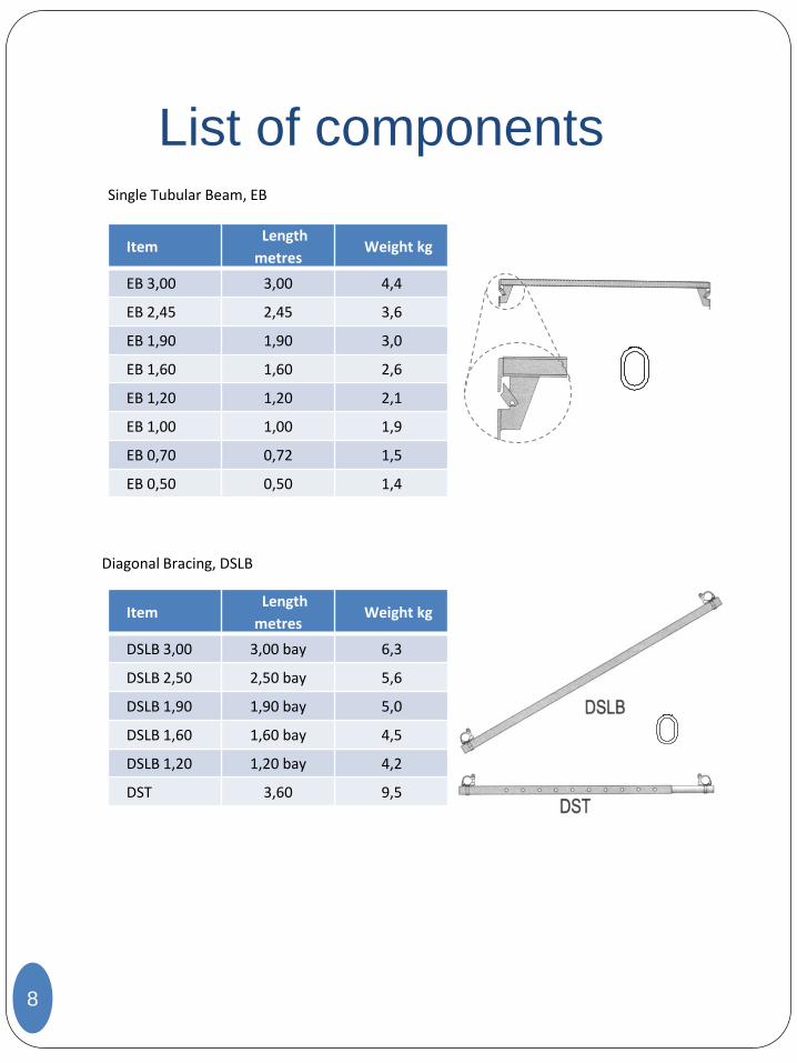
List of components Single Tubular Beam, EB
8
Diagonal Bracing, DSLB
Item Length
metres Weight kg
EB 3,00 3,00 4,4
EB 2,45 2,45 3,6
EB 1,90 1,90 3,0
EB 1,60 1,60 2,6
EB 1,20 1,20 2,1
EB 1,00 1,00 1,9
EB 0,70 0,72 1,5
EB 0,50 0,50 1,4
Item Length
metres Weight kg
DSLB 3,00 3,00 bay 6,3
DSLB 2,50 2,50 bay 5,6
DSLB 1,90 1,90 bay 5,0
DSLB 1,60 1,60 bay 4,5
DSLB 1,20 1,20 bay 4,2
DST 3,60 9,5
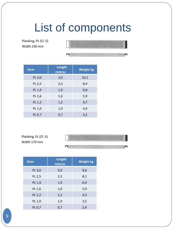
List of components Planking, PL (Cl. 5)
9
Item Length
metres Weight kg
PL 3,0 3,0 10,1
PL 2,5 2,5 8,4
PL 1,9 1,9 6,8
PL 1,6 1,6 5,9
PL 1,2 1,2 4,7
PL 1,0 1,0 4,0
PL 0,7 0,7 3,2
Width 230 mm
Planking, PL (Cl. 5)
Width 170 mm
Item Length
metres Weight kg
PL 3,0 3,0 9,6
PL 2,5 2,5 8,1
PL 1,9 1,9 6,9
PL 1,6 1,6 5,9
PL 1,2 1,2 4,3
PL 1,0 1,0 3,5
PL 0,7 0,7 2,4
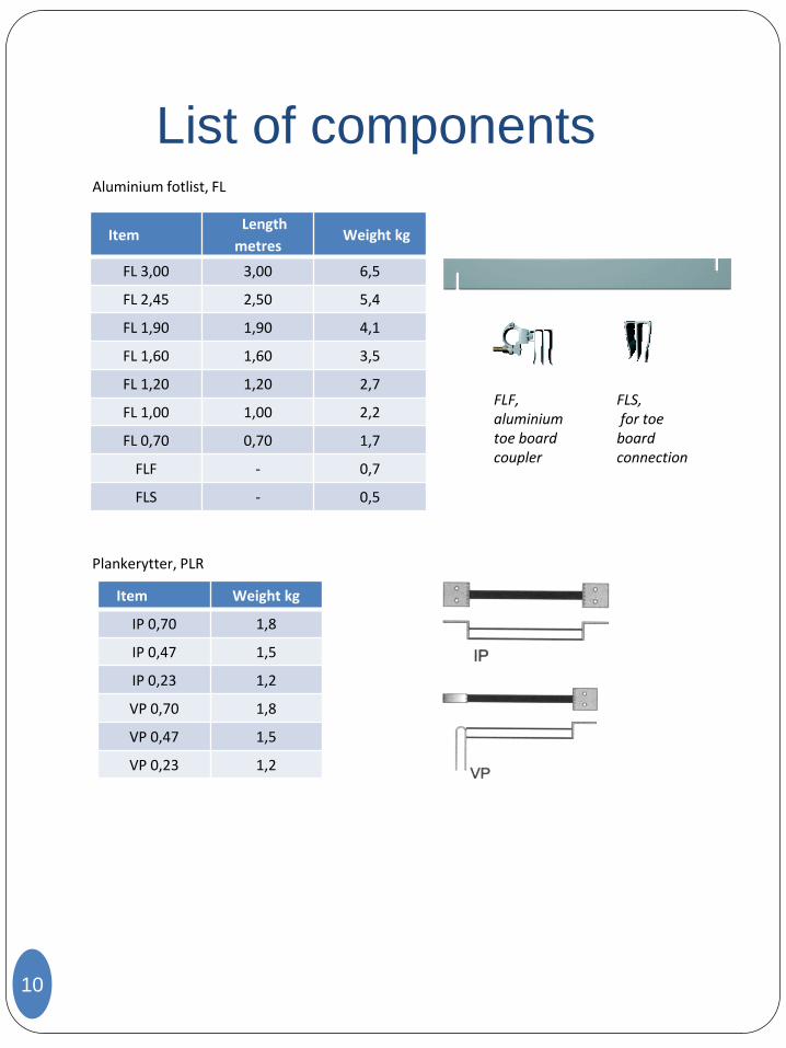
List of components Aluminium fotlist, FL
10
Item Length
metres Weight kg
FL 3,00 3,00 6,5
FL 2,45 2,50 5,4
FL 1,90 1,90 4,1
FL 1,60 1,60 3,5
FL 1,20 1,20 2,7
FL 1,00 1,00 2,2
FL 0,70 0,70 1,7
FLF - 0,7
FLS - 0,5
Plankerytter, PLR
Item Weight kg
IP 0,70 1,8
IP 0,47 1,5
IP 0,23 1,2
VP 0,70 1,8
VP 0,47 1,5
VP 0,23 1,2
FLF, aluminium toe board coupler
FLS, for toe board connection
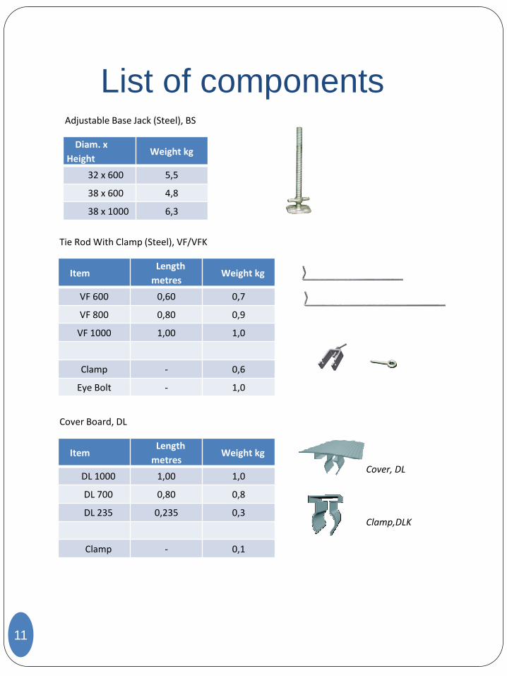
List of components Adjustable Base Jack (Steel), BS
11
Tie Rod With Clamp (Steel), VF/VFK
Diam. x
Height Weight kg
32 x 600 5,5
38 x 600 4,8
38 x 1000 6,3
Item Length
metres Weight kg
VF 600 0,60 0,7
VF 800 0,80 0,9
VF 1000 1,00 1,0
Clamp - 0,6
Eye Bolt - 1,0
Cover Board, DL
Item Length
metres Weight kg
DL 1000 1,00 1,0
DL 700 0,80 0,8
DL 235 0,235 0,3
Clamp - 0,1
Cover, DL
Clamp,DLK
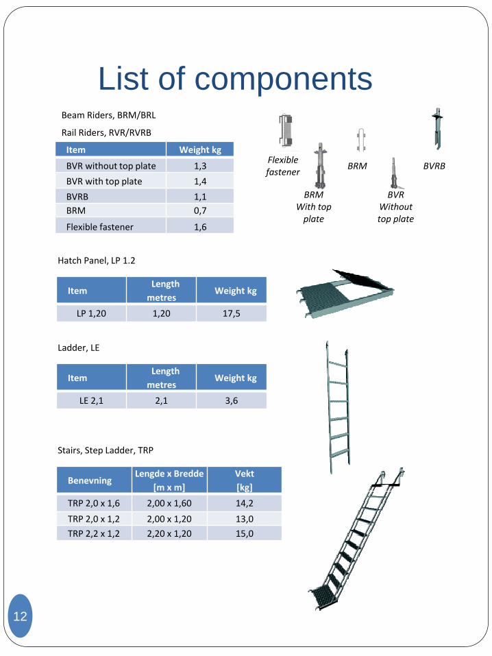
List of components Beam Riders, BRM/BRL
Rail Riders, RVR/RVRB
12
Hatch Panel, LP 1.2
Item Weight kg
BVR without top plate 1,3
BVR with top plate 1,4
BVRB 1,1
BRM 0,7
Flexible fastener 1,6
Item Length
metres Weight kg
LP 1,20 1,20 17,5
Ladder, LE
Item Length
metres Weight kg
LE 2,1 2,1 3,6
Flexible fastener
BRM BVRB
BRM With top
plate
BVR Without top plate
Stairs, Step Ladder, TRP
Benevning Lengde x Bredde
[m x m]
Vekt
[kg]
TRP 2,0 x 1,6 2,00 x 1,60 14,2
TRP 2,0 x 1,2 2,00 x 1,20 13,0
TRP 2,2 x 1,2 2,20 x 1,20 15,0
List of components
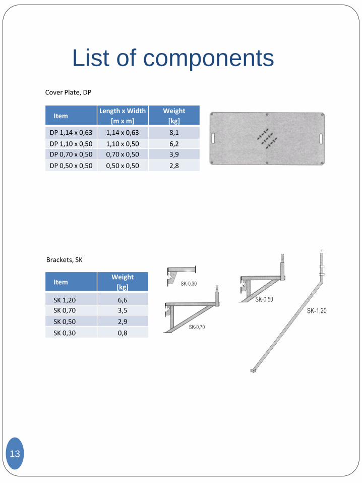
Cover Plate, DP
13
Brackets, SK
Item Length x Width
[m x m]
Weight
[kg]
DP 1,14 x 0,63 1,14 x 0,63 8,1
DP 1,10 x 0,50 1,10 x 0,50 6,2
DP 0,70 x 0,50 0,70 x 0,50 3,9
DP 0,50 x 0,50 0,50 x 0,50 2,8
Item Weight
[kg]
SK 1,20 6,6
SK 0,70 3,5
SK 0,50 2,9
SK 0,30 0,8
List of components
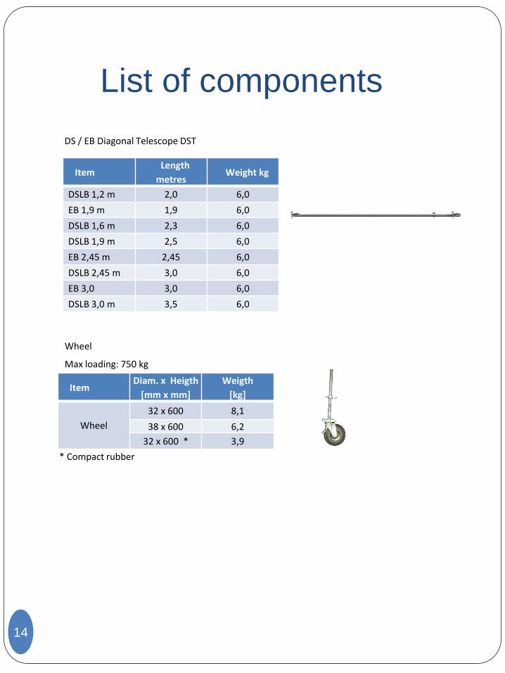
Wheel
Max loading: 750 kg
14
Item Diam. x Heigth
[mm x mm]
Weigth
[kg]
Wheel
32 x 600 8,1
38 x 600 6,2
32 x 600 * 3,9
* Compact rubber
DS / EB Diagonal Telescope DST
Item Length
metres Weight kg
DSLB 1,2 m 2,0 6,0
EB 1,9 m 1,9 6,0
DSLB 1,6 m 2,3 6,0
DSLB 1,9 m 2,5 6,0
EB 2,45 m 2,45 6,0
DSLB 2,45 m 3,0 6,0
EB 3,0 3,0 6,0
DSLB 3,0 m 3,5 6,0
Recommended scaffold widths
15
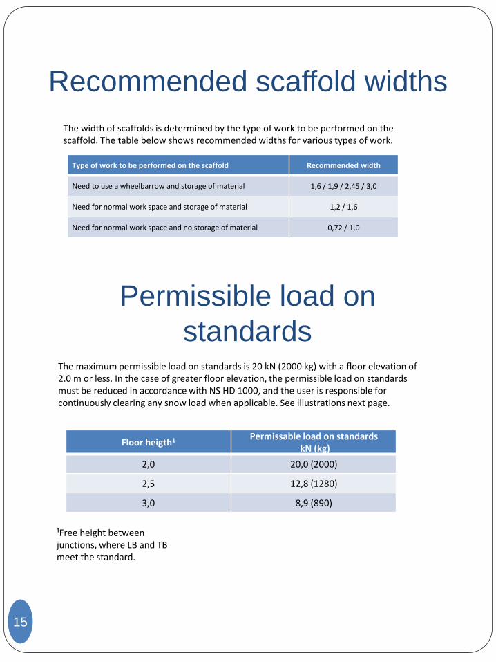
The width of scaffolds is determined by the type of work to be performed on the scaffold. The table below shows recommended widths for various types of work.
Type of work to be performed on the scaffold Recommended width
Need to use a wheelbarrow and storage of material 1,6 / 1,9 / 2,45 / 3,0
Need for normal work space and storage of material 1,2 / 1,6
Need for normal work space and no storage of material 0,72 / 1,0
Permissible load on
standards The maximum permissible load on standards is 20 kN (2000 kg) with a floor elevation of 2.0 m or less. In the case of greater floor elevation, the permissible load on standards must be reduced in accordance with NS HD 1000, and the user is responsible for continuously clearing any snow load when applicable. See illustrations next page.
Floor heigth1 Permissable load on standards
kN (kg)
2,0 20,0 (2000)
2,5 12,8 (1280)
3,0 8,9 (890)
¹Free height between junctions, where LB and TB meet the standard.
Permissible load on standards
16
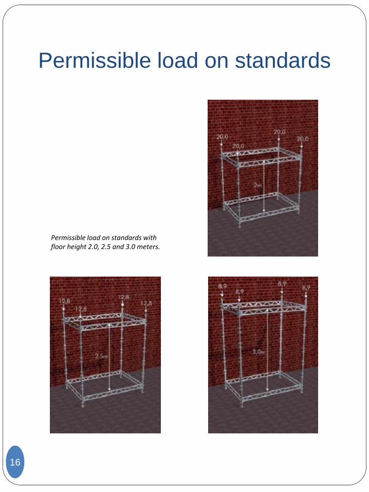
Permissible load on standards with floor height 2.0, 2.5 and 3.0 meters.
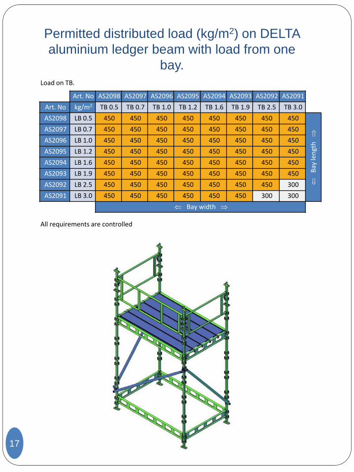
Permitted distributed load (kg/m2) on DELTA
aluminium ledger beam with load from one
bay.
17
All requirements are controlled
Load on TB.
Art. No AS2098 AS2097 AS2096 AS2095 AS2094 AS2093 AS2092 AS2091
Art. No kg/m2 TB 0.5 TB 0.7 TB 1.0 TB 1.2 TB 1.6 TB 1.9 TB 2.5 TB 3.0
AS2098 LB 0.5 450 450 450 450 450 450 450 450
Bay
len
gth
AS2097 LB 0.7 450 450 450 450 450 450 450 450
AS2096 LB 1.0 450 450 450 450 450 450 450 450
AS2095 LB 1.2 450 450 450 450 450 450 450 450
AS2094 LB 1.6 450 450 450 450 450 450 450 450
AS2093 LB 1.9 450 450 450 450 450 450 450 450
AS2092 LB 2.5 450 450 450 450 450 450 450 300
AS2091 LB 3.0 450 450 450 450 450 450 300 300
Bay width
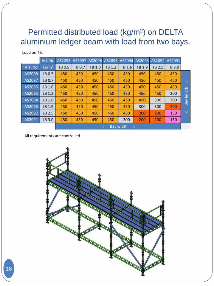
Permitted distributed load (kg/m2) on DELTA
aluminium ledger beam with load from two bays.
18
All requirements are controlled
Load on TB.
Art. No AS2098 AS2097 AS2096 AS2095 AS2094 AS2093 AS2092 AS2091
Art. No kg/m2 TB 0.5 TB 0.7 TB 1.0 TB 1.2 TB 1.6 TB 1.9 TB 2.5 TB 3.0
AS2098 LB 0.5 450 450 450 450 450 450 450 450
Bay
len
gth
AS2097 LB 0.7 450 450 450 450 450 450 450 450
AS2096 LB 1.0 450 450 450 450 450 450 450 450
AS2095 LB 1.2 450 450 450 450 450 450 450 300
AS2094 LB 1.6 450 450 450 450 450 450 300 300
AS2093 LB 1.9 450 450 450 450 450 300 300 200
AS2092 LB 2.5 450 450 450 450 450 200 200 150
AS2091 LB 3.0 450 450 450 450 300 200 200 150
Bay width
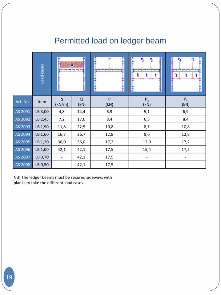
Permitted load on ledger beam
19
NB! The ledger beams must be secured sideways with planks to take the different load cases.
Load
cas
es
Art. No. Item q
(kN/m) Q
(kN) P
(kN) P3
(kN) P4
(kN)
AS 2091 LB 3,00 4,8 14,4 6,9 5,1 6,9
AS 2092 LB 2,45 7,2 17,6 8,4 6,3 8,4
AS 2093 LB 1,90 11,8 22,5 10,8 8,1 10,8
AS 2094 LB 1,60 16,7 26,7 12,8 9,6 12,8
AS 2095 LB 1,20 30,0 36,0 17,2 12,9 17,2
AS 2096 LB 1,00 42,1 42,1 17,5 15,4 17,5
AS 2097 LB 0,70 - 42,1 17,5 - -
AS 2098 LB 0,50 - 42,1 17,5 - -
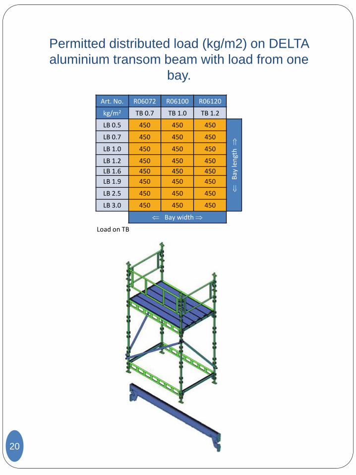
Permitted distributed load (kg/m2) on DELTA
aluminium transom beam with load from one
bay.
20
Load on TB
Art. No. R06072 R06100 R06120
kg/m2 TB 0.7 TB 1.0 TB 1.2
LB 0.5 450 450 450
Bay
len
gth
LB 0.7 450 450 450
LB 1.0 450 450 450
LB 1.2 450 450 450
LB 1.6 450 450 450
LB 1.9 450 450 450
LB 2.5 450 450 450
LB 3.0 450 450 450
Bay width
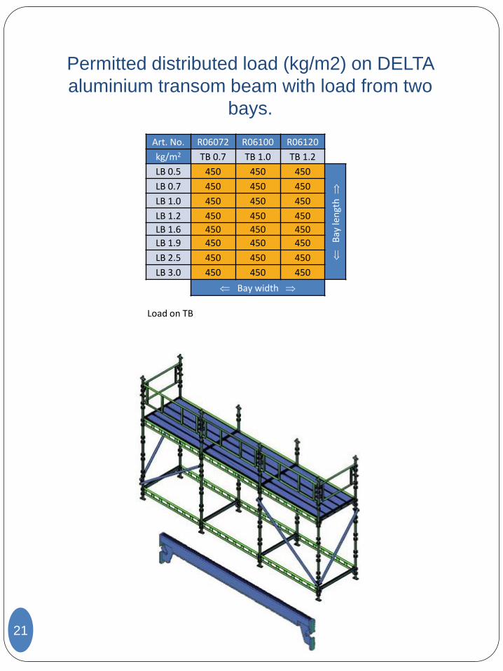
Permitted distributed load (kg/m2) on DELTA
aluminium transom beam with load from two
bays.
21
Load on TB
Art. No. R06072 R06100 R06120
kg/m2 TB 0.7 TB 1.0 TB 1.2
LB 0.5 450 450 450
Bay
len
gth
LB 0.7 450 450 450
LB 1.0 450 450 450
LB 1.2 450 450 450
LB 1.6 450 450 450
LB 1.9 450 450 450
LB 2.5 450 450 450
LB 3.0 450 450 450
Bay width
Permissible building height
22
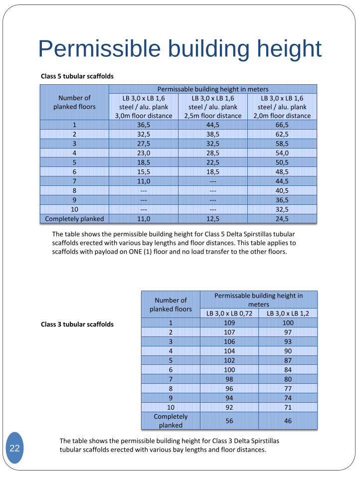
Class 5 tubular scaffolds
Number of planked floors
Permissable building height in meters LB 3,0 x LB 1,6
steel / alu. plank 3,0m floor distance
LB 3,0 x LB 1,6 steel / alu. plank
2,5m floor distance
LB 3,0 x LB 1,6 steel / alu. plank
2,0m floor distance 1 36,5 44,5 66,5
2 32,5 38,5 62,5
3 27,5 32,5 58,5
4 23,0 28,5 54,0
5 18,5 22,5 50,5
6 15,5 18,5 48,5
7 11,0 --- 44,5
8 --- --- 40,5
9 --- --- 36,5
10 --- --- 32,5
Completely planked 11,0 12,5 24,5
The table shows the permissible building height for Class 5 Delta Spirstillas tubular scaffolds erected with various bay lengths and floor distances. This table applies to scaffolds with payload on ONE (1) floor and no load transfer to the other floors.
Class 3 tubular scaffolds
Number of planked floors
Permissable building height in meters
LB 3,0 x LB 0,72 LB 3,0 x LB 1,2
1 109 100
2 107 97
3 106 93
4 104 90
5 102 87
6 100 84
7 98 80
8 96 77
9 94 74
10 92 71 Completely
planked 56 46
The table shows the permissible building height for Class 3 Delta Spirstillas tubular scaffolds erected with various bay lengths and floor distances.
General conditions
23
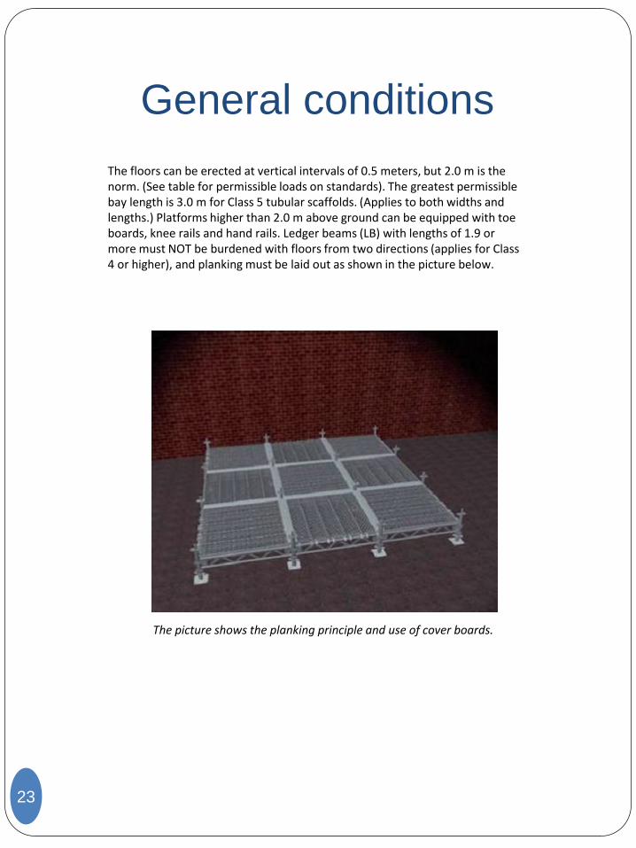
The floors can be erected at vertical intervals of 0.5 meters, but 2.0 m is the norm. (See table for permissible loads on standards). The greatest permissible bay length is 3.0 m for Class 5 tubular scaffolds. (Applies to both widths and lengths.) Platforms higher than 2.0 m above ground can be equipped with toe boards, knee rails and hand rails. Ledger beams (LB) with lengths of 1.9 or more must NOT be burdened with floors from two directions (applies for Class 4 or higher), and planking must be laid out as shown in the picture below.
The picture shows the planking principle and use of cover boards.
Inspection and maintenance
24
The scaffold shall be inspected visually prior to use in order to check for cracks in welded joints and galvanic corrosion. Damaged material must be isolated and possibly rejected. It must never be done any modifications of the components (welding/bending/straightening etc) without obtaining new certification of the components. This is particularly important for load-bearing components. The vertical standards must never be cut in half. Loose parts (locks, bolts etc.) must be greased regularly. Moreover defect components can be shipped to the supplier for repair/maintenance. Erected scaffold shall regularly be controlled by qualified personnel to assure that any defects are detected at an early stage. Inspections must also include checking foundations to prevent scaffolds from sinking into the ground and making sure that base boards are securely fastened. Is must be expected that scaffolds fabricated in steel and aluminium will be subject to galvanic corrosion under special atmospheric conditions. In time, this type of attack could entail structural deterioration of the component unless corrective measures are implemented. However, meticulous galvanisation of steel components, along with regular inspection and maintenance can help detect such defects. Galvanic corrosion can be spotted by the naked eye as ingrained white powder at the surface of the aluminium. Most important is couplers being of recent date, such that the layer of zinc is entire and as thick as possible. Aluminium in contact with bare steel where moisture has access and seldom dries out will lead to corrosion. To be on the safe side one should have regular control for scaffolds that stand assembled for longer time. For scaffolds that are assembled for 2-3 months or longer, one can loosen a few couplers to check the surface of the aluminium pipe. If it turns out that corrosion has already started, (one can then see the white coat, and perhaps some white oxide powder) one can try moving the coupler a little to the side and tighten it again. Remember safety actions if one need to move couplers. If the corrosion is significant, one need to make sure the zinc coating is complete and reasonable thick and perhaps to assemble a newer coupler. Flushing of disassembled components by fresh water should also be done after long time off-shore use (3 months or more). Couplers shall be cleaned and greased when needed. Couplers where the zinc coating is worn down in the contact surface towards the piping, is smeared with cold zinc, or one can deliver the couplers in for hot galvanization or flame spraying with zinc. It is then assumed that all joint bolts are in good condition. Couplers that are worn in the joints shall be rejected. Bolt and nut are easy to replace. Bare steel surface must not come in contact with aluminium.
Inspection and
maintenance
25
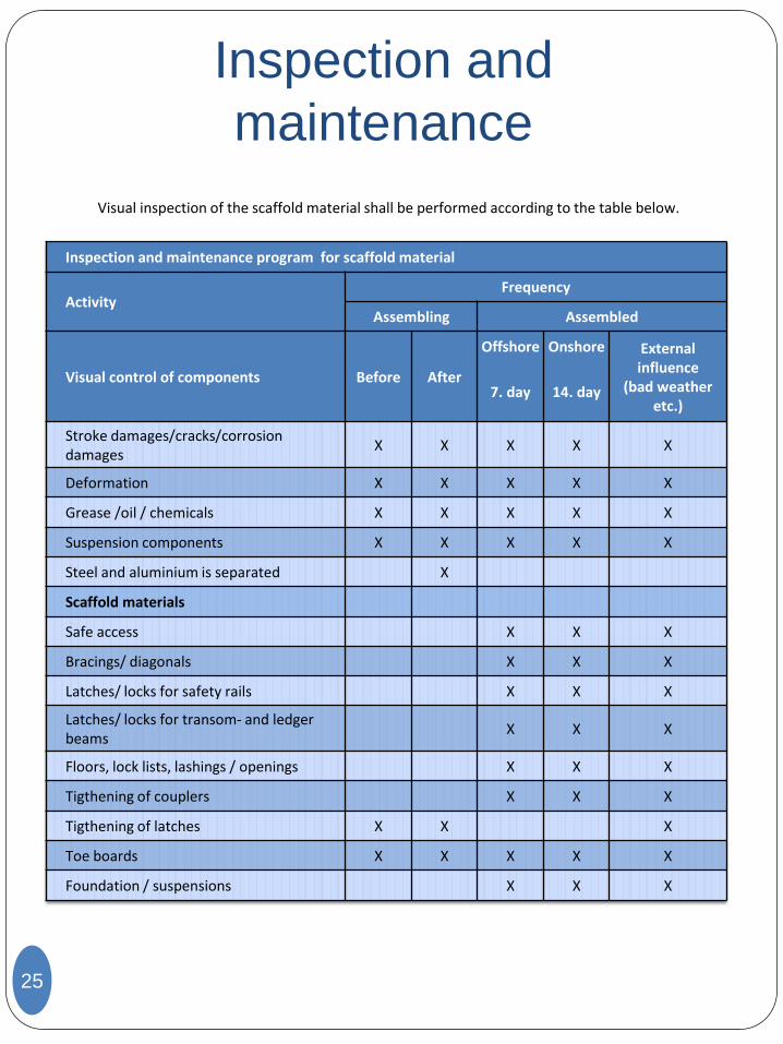
Visual inspection of the scaffold material shall be performed according to the table below.
Inspection and maintenance program for scaffold material
Activity Frequency
Assembling Assembled
Visual control of components Before After
Offshore Onshore External influence
(bad weather etc.)
7. day 14. day
Stroke damages/cracks/corrosion damages
X X X X X
Deformation X X X X X
Grease /oil / chemicals X X X X X
Suspension components X X X X X
Steel and aluminium is separated X
Scaffold materials
Safe access X X X
Bracings/ diagonals X X X
Latches/ locks for safety rails X X X
Latches/ locks for transom- and ledger beams
X X X
Floors, lock lists, lashings / openings X X X
Tigthening of couplers X X X
Tigthening of latches X X X
Toe boards X X X X X
Foundation / suspensions X X X
Bracing
26
All scaffolds must be braced prior to use, and this is perhaps the scaffolder’s most important task. We have three types of braces: vertical stays, tie bars and horizontal stays VERTICAL STAYS: The scaffold is braced with full-length vertical stays between the outer standards at every 4th bay and always in the end bays. In other words, you must install vertical stays in the first bay and subsequently at every 4th bay. Regardless of how many bays there are, you must always install vertical stays in the first and last bay of the scaffold. There should be a maximum of 20 cm from the vertical stay clamp to the nearest LB/EB. It is therefore not a prerequisite that a vertical stay reaches from the bottom to the top of the same row of standards. TIE BARS: These braces are used at each end (in the diagonal direction) and must always be used. They are fitted in the same manner as the vertical stays. HORIZONTAL STAYS: These are used horizontally and between two pairs of standards to absorb torsion forces. Scaffolds with heights exceeding 24 metres must have horizontal stays at top and bottom, as well as every 24 vertical metres. Scaffolds with heights of less than 24 metres do not require horizontal stays. In the longitudinal direction of the scaffold, horizontal stays must be fitted in every 8th bay, as well as in each end bay. EXAMPLE: A scaffold measuring 30 x 1.2 x 60 m ( L x W x H ). Horizontal stays are fitted at the bottom of the first bay, at a height of 24 metres, at a height of 48 metres, and at the top. This should be performed for every 8th bay, and in the end bay.
Fastening
27
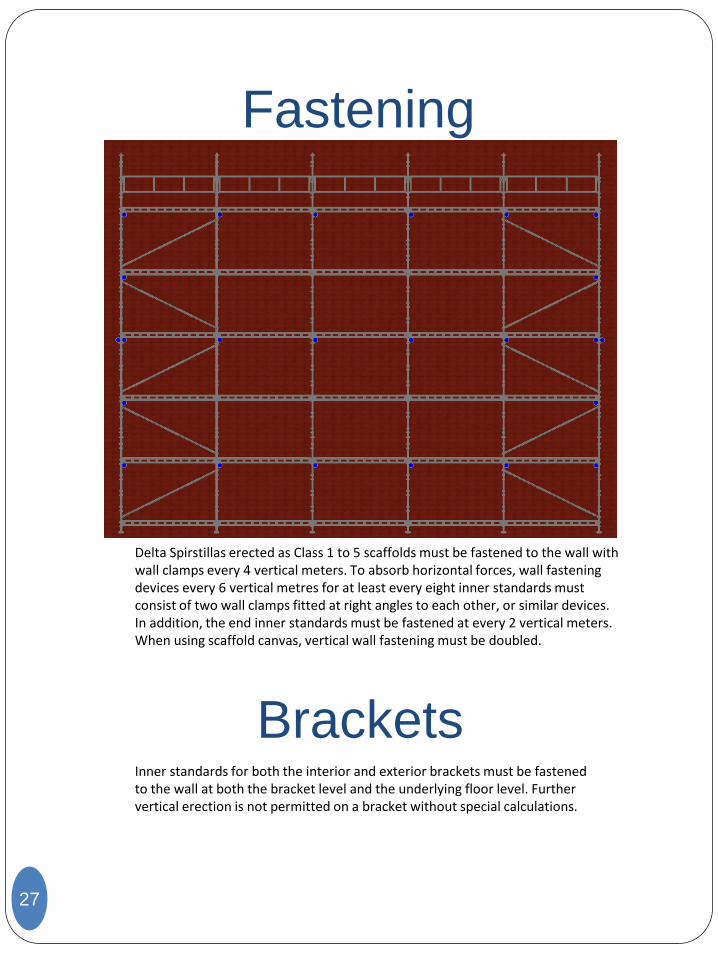
Brackets Inner standards for both the interior and exterior brackets must be fastened to the wall at both the bracket level and the underlying floor level. Further vertical erection is not permitted on a bracket without special calculations.
Delta Spirstillas erected as Class 1 to 5 scaffolds must be fastened to the wall with wall clamps every 4 vertical meters. To absorb horizontal forces, wall fastening devices every 6 vertical metres for at least every eight inner standards must consist of two wall clamps fitted at right angles to each other, or similar devices. In addition, the end inner standards must be fastened at every 2 vertical meters. When using scaffold canvas, vertical wall fastening must be doubled.
28
Anti-falling
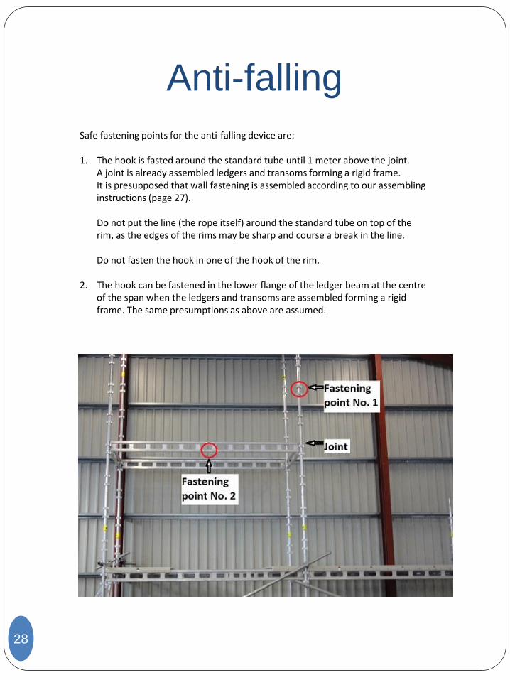
Safe fastening points for the anti-falling device are: 1. The hook is fasted around the standard tube until 1 meter above the joint. A joint is already assembled ledgers and transoms forming a rigid frame. It is presupposed that wall fastening is assembled according to our assembling
instructions (page 27). Do not put the line (the rope itself) around the standard tube on top of the
rim, as the edges of the rims may be sharp and course a break in the line. Do not fasten the hook in one of the hook of the rim. 2. The hook can be fastened in the lower flange of the ledger beam at the centre
of the span when the ledgers and transoms are assembled forming a rigid frame. The same presumptions as above are assumed.
Scaffold system
29
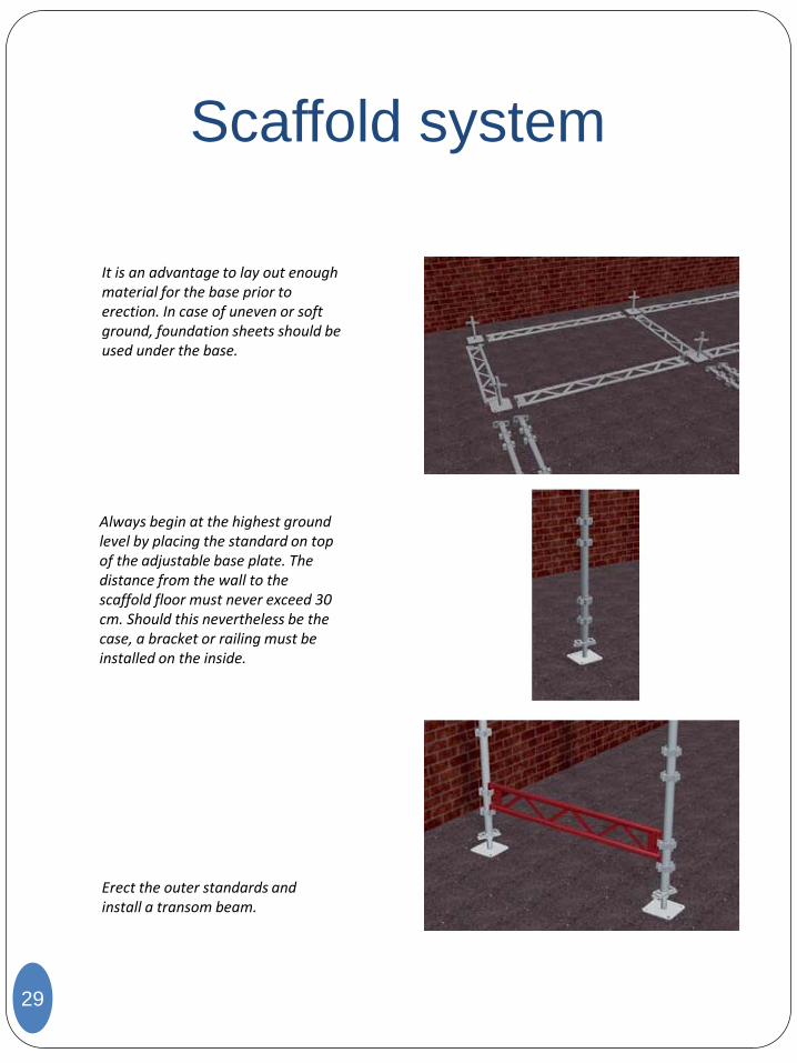
It is an advantage to lay out enough material for the base prior to erection. In case of uneven or soft ground, foundation sheets should be used under the base.
Always begin at the highest ground level by placing the standard on top of the adjustable base plate. The distance from the wall to the scaffold floor must never exceed 30 cm. Should this nevertheless be the case, a bracket or railing must be installed on the inside.
Erect the outer standards and install a transom beam.
Scaffold system
30
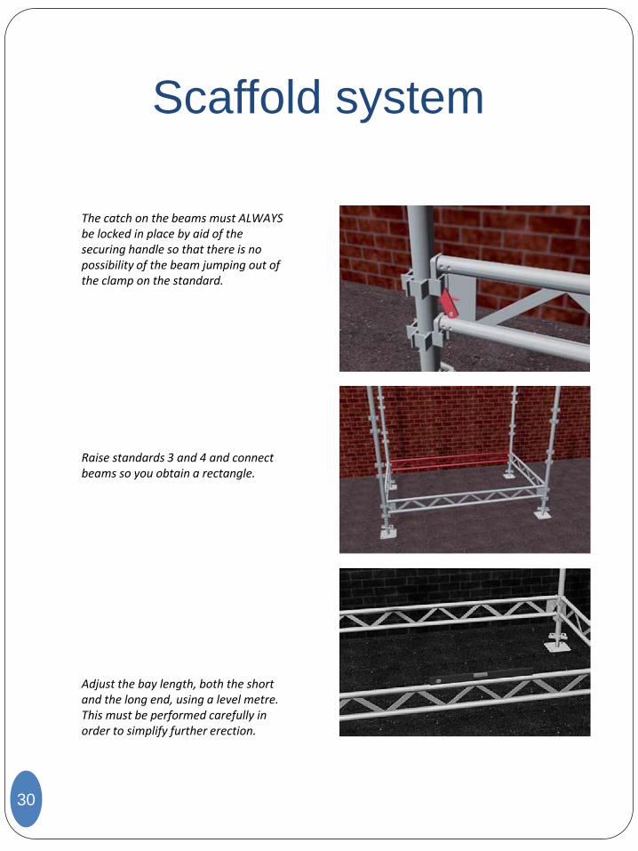
The catch on the beams must ALWAYS be locked in place by aid of the securing handle so that there is no possibility of the beam jumping out of the clamp on the standard.
Raise standards 3 and 4 and connect beams so you obtain a rectangle.
Adjust the bay length, both the short and the long end, using a level metre. This must be performed carefully in order to simplify further erection.
Scaffold system
31
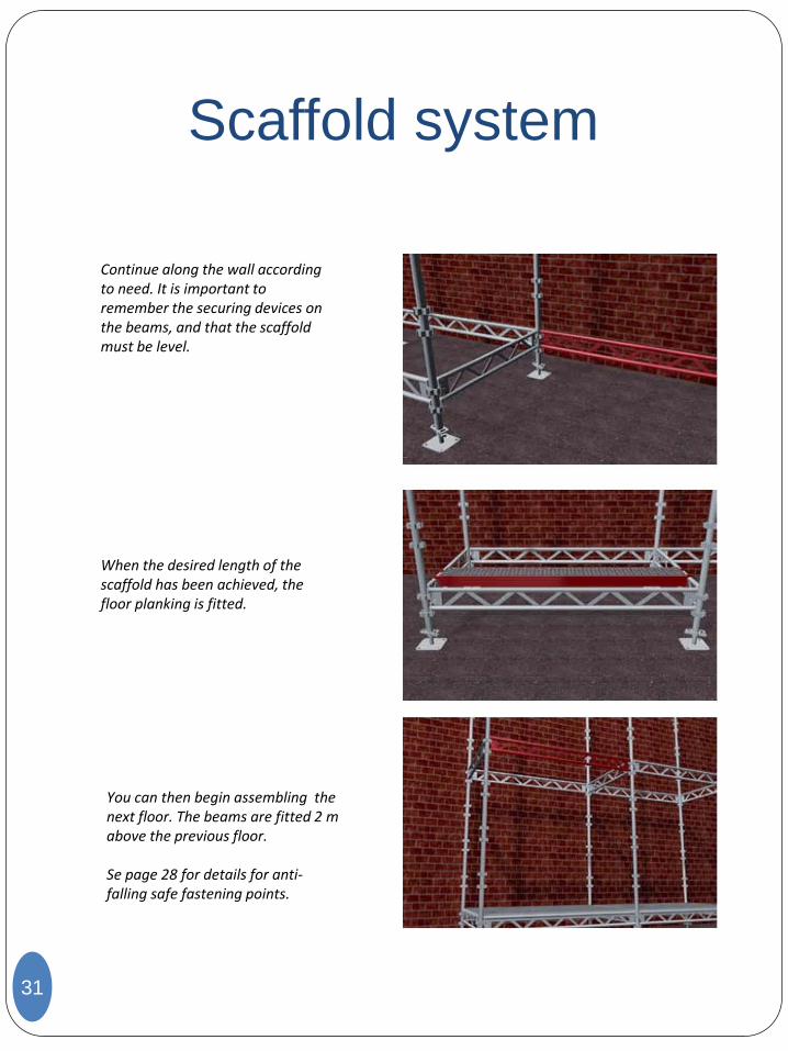
Continue along the wall according to need. It is important to remember the securing devices on the beams, and that the scaffold must be level.
When the desired length of the scaffold has been achieved, the floor planking is fitted.
You can then begin assembling the next floor. The beams are fitted 2 m above the previous floor. Se page 28 for details for anti-falling safe fastening points.
Scaffold system
32
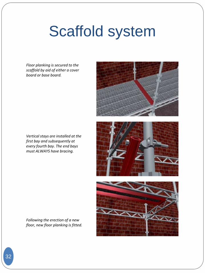
Floor planking is secured to the scaffold by aid of either a cover board or base board.
Vertical stays are installed at the first bay and subsequently at every fourth bay. The end bays must ALWAYS have bracing.
Following the erection of a new floor, new floor planking is fitted.
Scaffold system
33
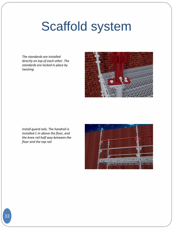
The standards are installed directly on top of each other. The standards are locked in place by twisting.
Install guard rails. The handrail is installed 1 m above the floor, and the knee rail half way between the floor and the top rail.
Scaffold system
34
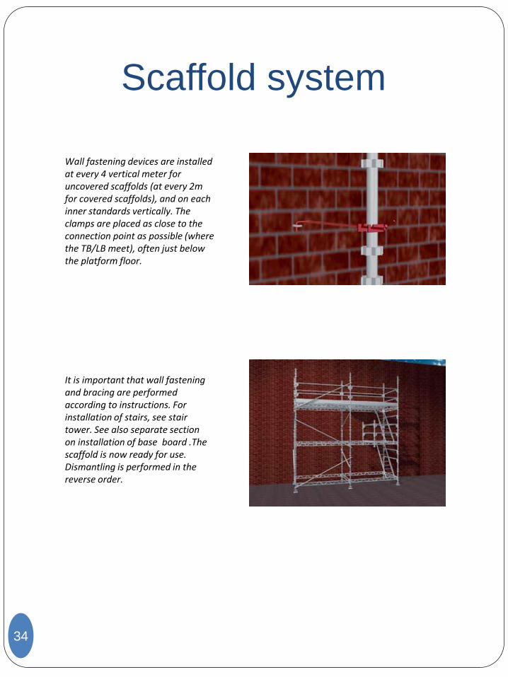
Wall fastening devices are installed at every 4 vertical meter for uncovered scaffolds (at every 2m for covered scaffolds), and on each inner standards vertically. The clamps are placed as close to the connection point as possible (where the TB/LB meet), often just below the platform floor.
It is important that wall fastening and bracing are performed according to instructions. For installation of stairs, see stair tower. See also separate section on installation of base board .The scaffold is now ready for use. Dismantling is performed in the reverse order.
Mobile scaffolds
35
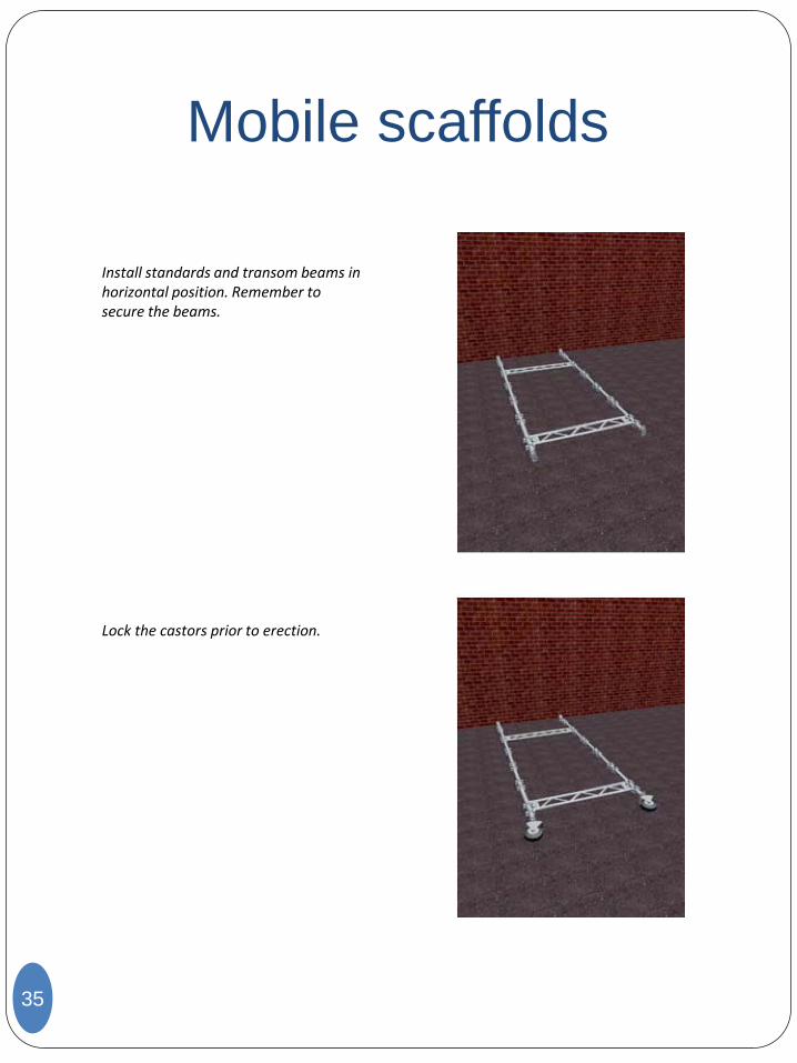
Install standards and transom beams in horizontal position. Remember to secure the beams.
Lock the castors prior to erection.
Mobile scaffolds
36
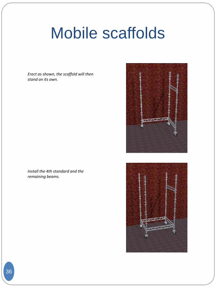
Erect as shown, the scaffold will then stand on its own.
Install the 4th standard and the remaining beams.
Mobile scaffolds
37
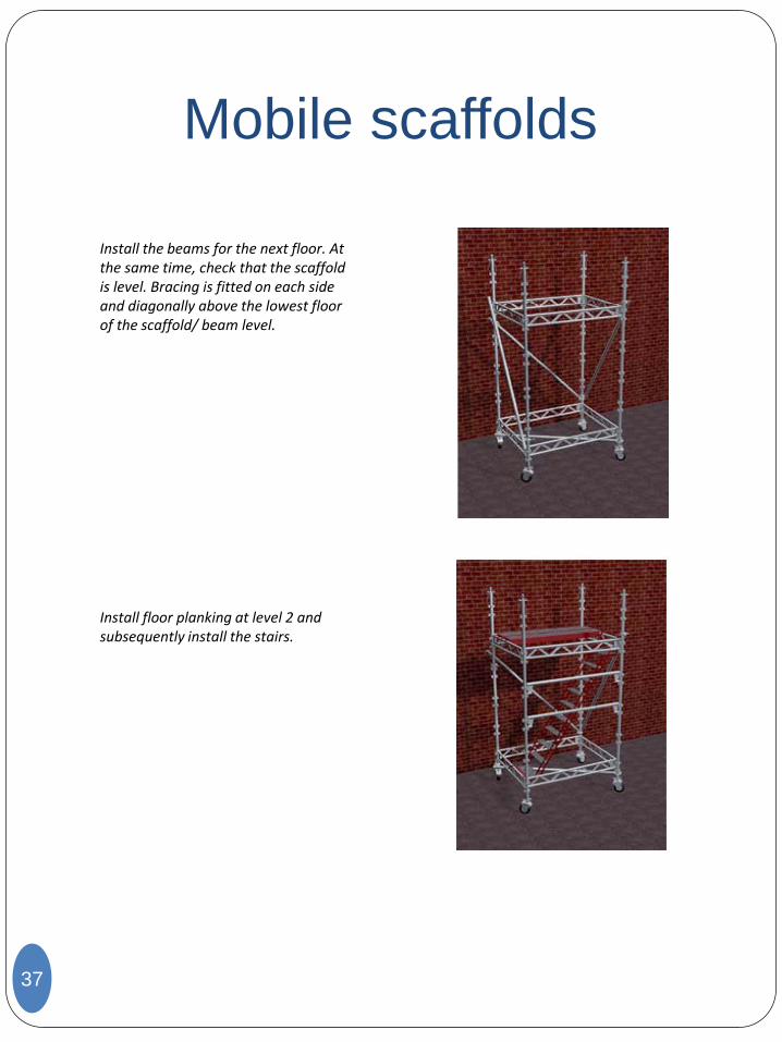
Install the beams for the next floor. At the same time, check that the scaffold is level. Bracing is fitted on each side and diagonally above the lowest floor of the scaffold/ beam level.
Install floor planking at level 2 and subsequently install the stairs.
Mobile scaffolds
38
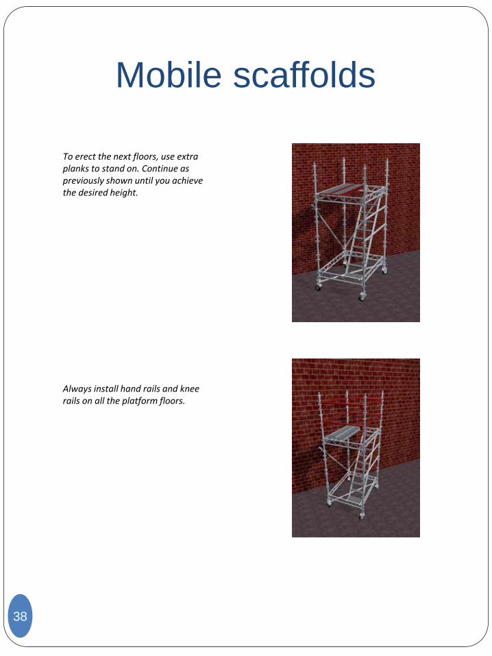
To erect the next floors, use extra planks to stand on. Continue as previously shown until you achieve the desired height.
Always install hand rails and knee rails on all the platform floors.
Mobile scaffolds
39
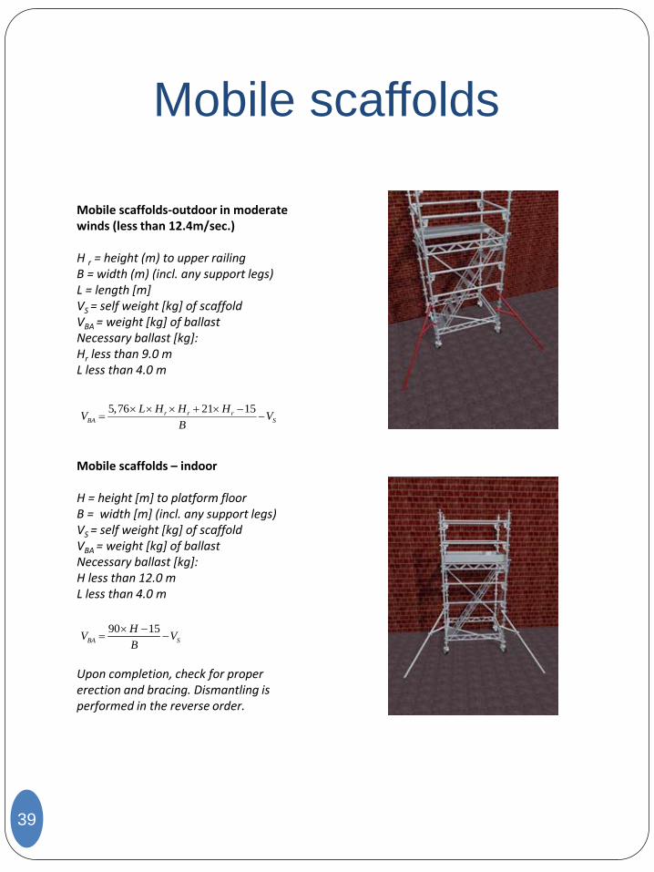
Mobile scaffolds-outdoor in moderate winds (less than 12.4m/sec.) H r = height (m) to upper railing B = width (m) (incl. any support legs) L = length [m] VS = self weight [kg] of scaffold VBA = weight [kg] of ballast Necessary ballast [kg]: Hr less than 9.0 m L less than 4.0 m Mobile scaffolds – indoor H = height [m] to platform floor B = width [m] (incl. any support legs) VS = self weight [kg] of scaffold VBA = weight [kg] of ballast Necessary ballast [kg]: H less than 12.0 m L less than 4.0 m Upon completion, check for proper erection and bracing. Dismantling is performed in the reverse order.
5,76 21 15r r rBA S
L H H HV V
B
90 15BA S
HV V
B
Stair tower 1.6 m x 1.2 m
40
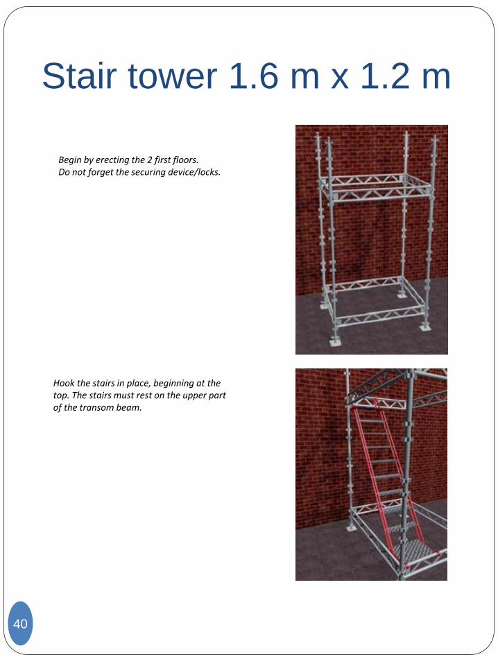
Begin by erecting the 2 first floors. Do not forget the securing device/locks.
Hook the stairs in place, beginning at the top. The stairs must rest on the upper part of the transom beam.
Stair tower 1.6 m x 1.2 m
41
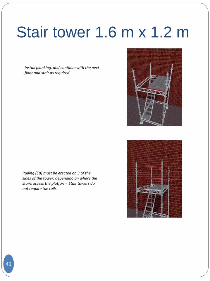
Install planking, and continue with the next floor and stair as required.
Railing (EB) must be erected on 3 of the sides of the tower, depending on where the stairs access the platform. Stair towers do not require toe rails.
Stair tower 1.6 m x 1.2 m
42
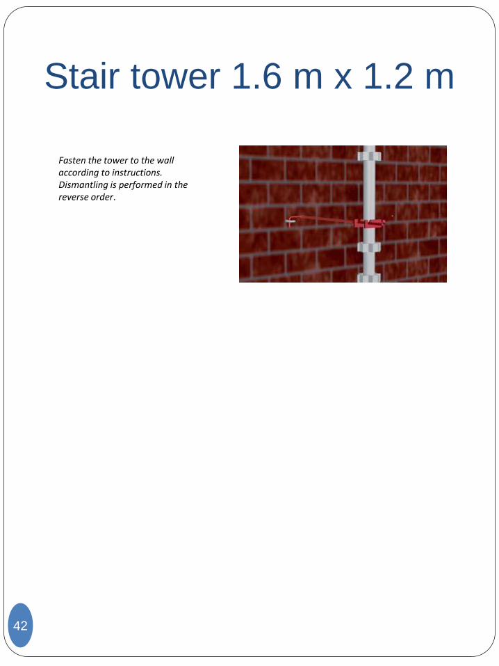
Fasten the tower to the wall according to instructions. Dismantling is performed in the reverse order.
Stairway
43
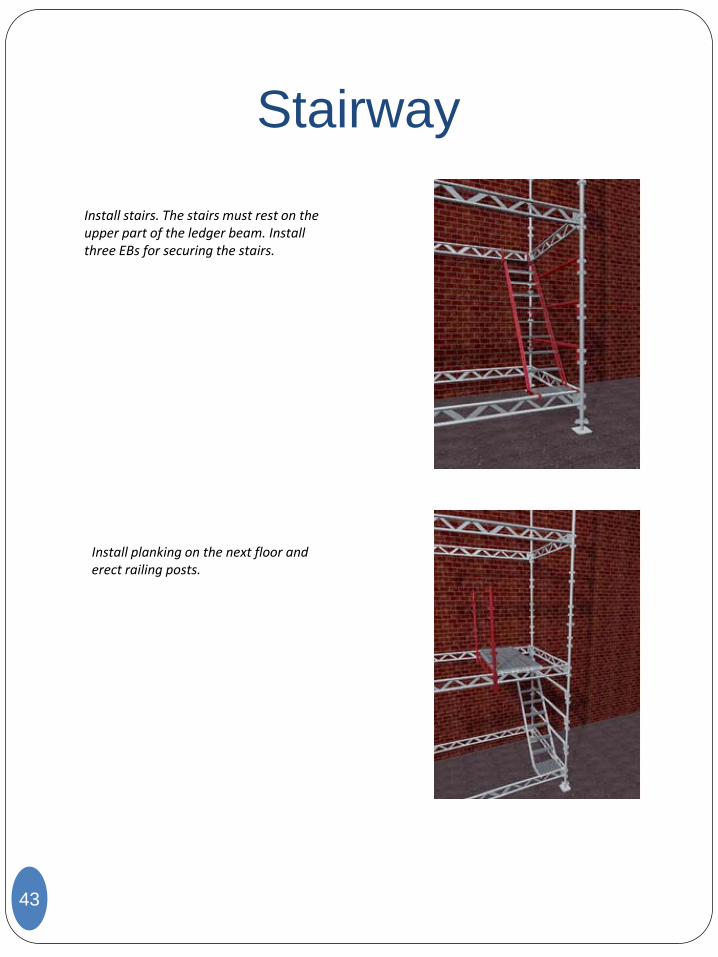
Install stairs. The stairs must rest on the upper part of the ledger beam. Install three EBs for securing the stairs.
Install planking on the next floor and erect railing posts.
Stairway
44
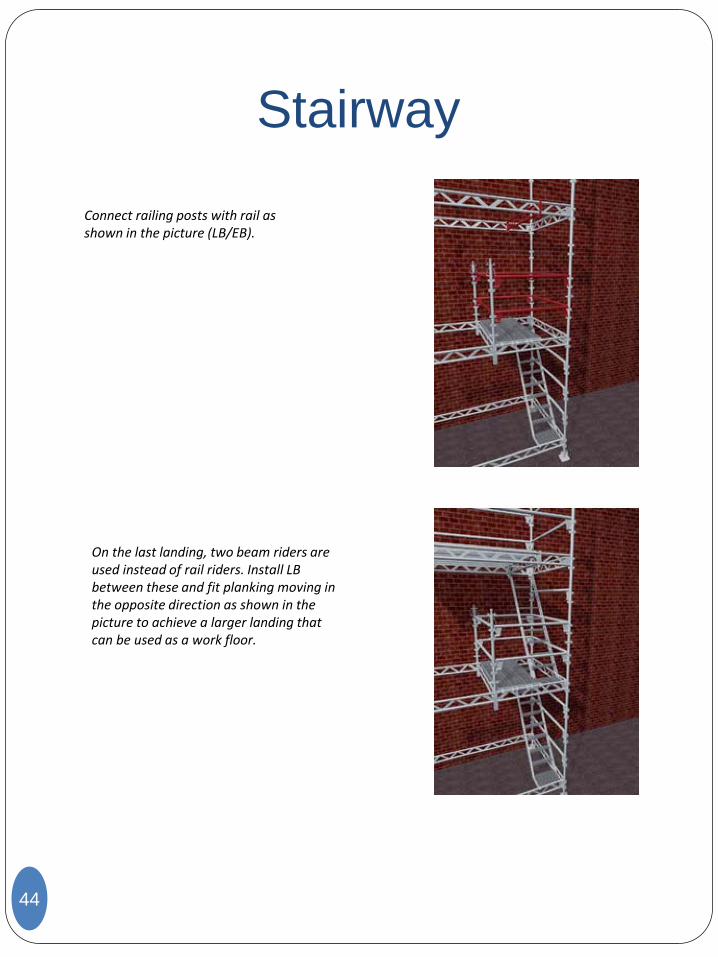
Connect railing posts with rail as shown in the picture (LB/EB).
On the last landing, two beam riders are used instead of rail riders. Install LB between these and fit planking moving in the opposite direction as shown in the picture to achieve a larger landing that can be used as a work floor.
Toe board
45
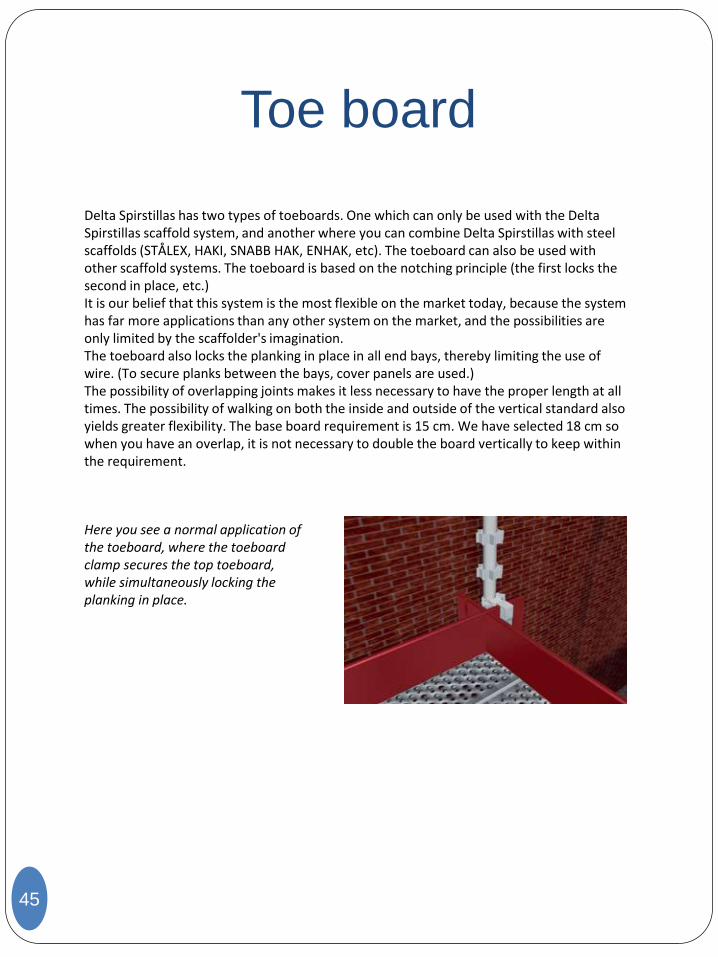
Delta Spirstillas has two types of toeboards. One which can only be used with the Delta Spirstillas scaffold system, and another where you can combine Delta Spirstillas with steel scaffolds (STÅLEX, HAKI, SNABB HAK, ENHAK, etc). The toeboard can also be used with other scaffold systems. The toeboard is based on the notching principle (the first locks the second in place, etc.) It is our belief that this system is the most flexible on the market today, because the system has far more applications than any other system on the market, and the possibilities are only limited by the scaffolder's imagination. The toeboard also locks the planking in place in all end bays, thereby limiting the use of wire. (To secure planks between the bays, cover panels are used.) The possibility of overlapping joints makes it less necessary to have the proper length at all times. The possibility of walking on both the inside and outside of the vertical standard also yields greater flexibility. The base board requirement is 15 cm. We have selected 18 cm so when you have an overlap, it is not necessary to double the board vertically to keep within the requirement.
Here you see a normal application of the toeboard, where the toeboard clamp secures the top toeboard, while simultaneously locking the planking in place.
Toe board
46
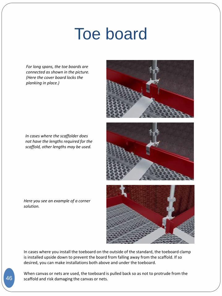
For long spans, the toe boards are connected as shown in the picture. (Here the cover board locks the planking in place.)
In cases where the scaffolder does not have the lengths required for the scaffold, other lengths may be used.
Here you see an example of a corner solution.
In cases where you install the toeboard on the outside of the standard, the toeboard clamp is installed upside down to prevent the board from falling away from the scaffold. If so desired, you can make installations both above and under the toeboard. When canvas or nets are used, the toeboard is pulled back so as not to protrude from the scaffold and risk damaging the canvas or nets.
Bracket 1.2 m (SK
1.2)
47
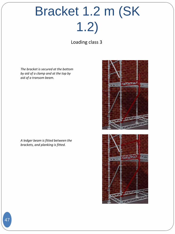
The bracket is secured at the bottom by aid of a clamp and at the top by aid of a transom beam.
A ledger beam is fitted between the brackets, and planking is fitted.
Loading class 3
Bracket 0.7 m (SK 0.72)
48
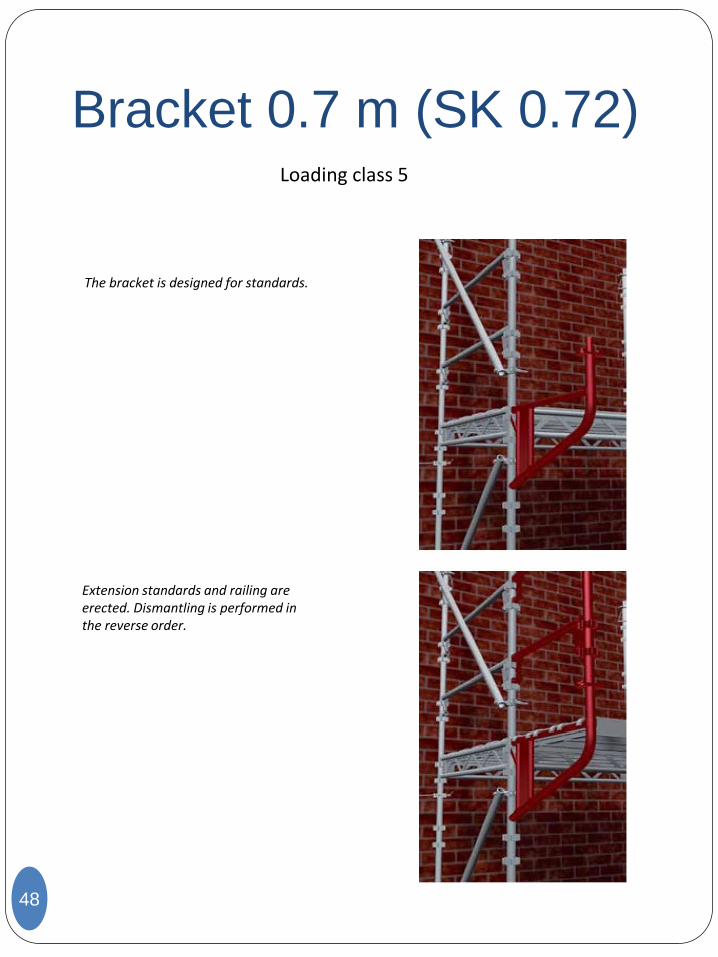
The bracket is designed for standards.
Extension standards and railing are erected. Dismantling is performed in the reverse order.
Loading class 5
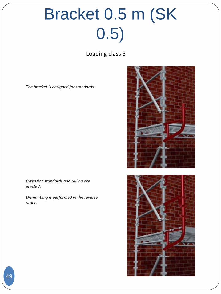
Bracket 0.5 m (SK
0.5)
49
The bracket is designed for standards.
Extension standards and railing are erected. Dismantling is performed in the reverse order.
Loading class 5
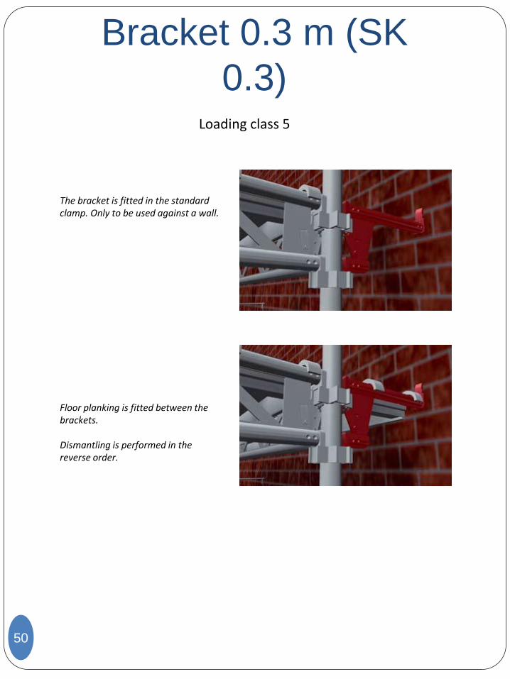
Bracket 0.3 m (SK
0.3)
50
The bracket is fitted in the standard clamp. Only to be used against a wall.
Floor planking is fitted between the brackets. Dismantling is performed in the reverse order.
Loading class 5
Beam riders (BRM/BRL)
51
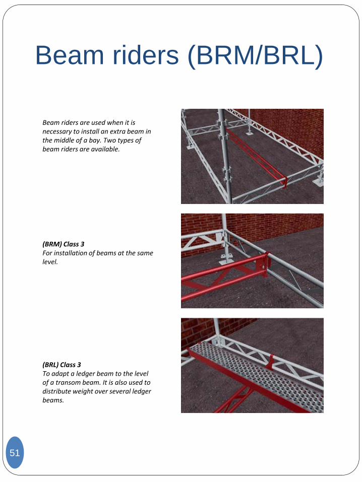
Beam riders are used when it is necessary to install an extra beam in the middle of a bay. Two types of beam riders are available.
(BRM) Class 3 For installation of beams at the same level.
(BRL) Class 3 To adapt a ledger beam to the level of a transom beam. It is also used to distribute weight over several ledger beams.
Scaffold pulley
52
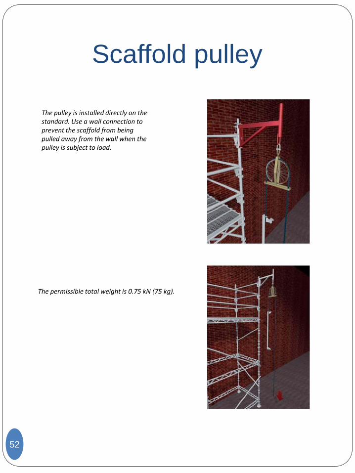
The pulley is installed directly on the standard. Use a wall connection to prevent the scaffold from being pulled away from the wall when the pulley is subject to load.
The permissible total weight is 0.75 kN (75 kg).
Hatch panel 1.2x0.6 (LP
1.2)
53
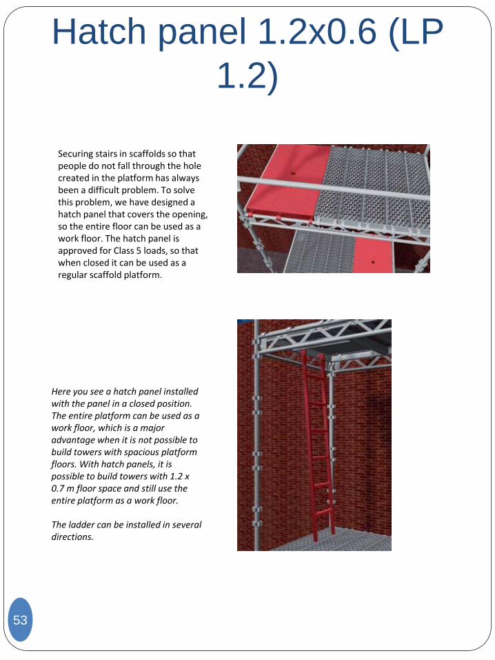
Securing stairs in scaffolds so that people do not fall through the hole created in the platform has always been a difficult problem. To solve this problem, we have designed a hatch panel that covers the opening, so the entire floor can be used as a work floor. The hatch panel is approved for Class 5 loads, so that when closed it can be used as a regular scaffold platform.
Here you see a hatch panel installed with the panel in a closed position. The entire platform can be used as a work floor, which is a major advantage when it is not possible to build towers with spacious platform floors. With hatch panels, it is possible to build towers with 1.2 x 0.7 m floor space and still use the entire platform as a work floor. The ladder can be installed in several directions.
54
Plank riders
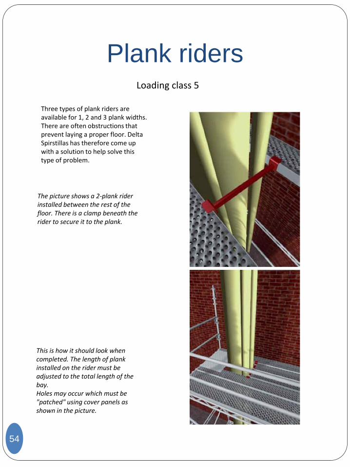
Three types of plank riders are available for 1, 2 and 3 plank widths. There are often obstructions that prevent laying a proper floor. Delta Spirstillas has therefore come up with a solution to help solve this type of problem.
The picture shows a 2-plank rider installed between the rest of the floor. There is a clamp beneath the rider to secure it to the plank.
Loading class 5
This is how it should look when completed. The length of plank installed on the rider must be adjusted to the total length of the bay. Holes may occur which must be "patched" using cover panels as shown in the picture.
DS/EB
Diagonal Telescope DST
55
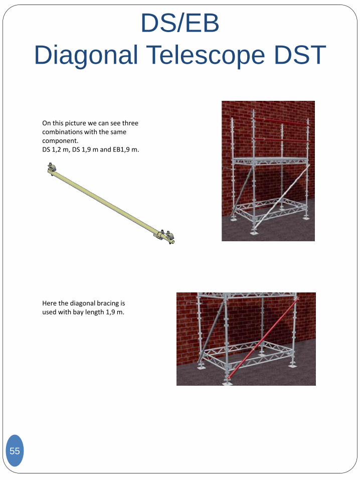
On this picture we can see three combinations with the same component. DS 1,2 m, DS 1,9 m and EB1,9 m.
Here the diagonal bracing is used with bay length 1,9 m.
Assembling of hanging scaffolds Grawlock- and SK-couplers
56
(If other suspensions are used, see our Offshore Suspension manual)
Both couplers are only allowed used in pairs.
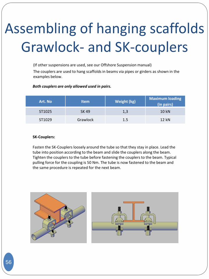
The couplers are used to hang scaffolds in beams via pipes or girders as shown in the examples below.
Art. No Item Weight (kg) Maximum loading
(in pairs)
ST1025 SK 49 1,3 10 kN
ST1029 Grawlock 1.5 12 kN
SK-Couplers: Fasten the SK-Couplers loosely around the tube so that they stay in place. Lead the tube into position according to the beam and slide the couplers along the beam. Tighten the couplers to the tube before fastening the couplers to the beam. Typical pulling force for the coupling is 50 Nm. The tube is now fastened to the beam and the same procedure is repeated for the next beam.
Assembling of hanging scaffolds Grawlock- and SK-couplers
57
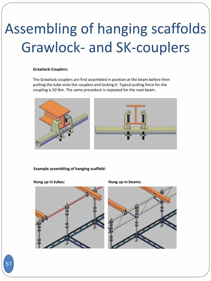
Grawlock-Couplers: The Grawlock couplers are first assembled in position at the beam before then putting the tube onto the couplers and locking it. Typical pulling force for the coupling is 50 Nm. The same procedure is repeated for the next beam.
Example assembling of hanging scaffold:
Hung up in tubes: Hung up in beams:
Assembling of
Hanging Scaffold
58
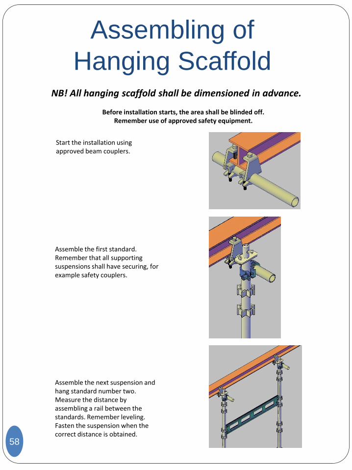
NB! All hanging scaffold shall be dimensioned in advance.
Before installation starts, the area shall be blinded off. Remember use of approved safety equipment.
Start the installation using approved beam couplers.
Assemble the first standard. Remember that all supporting suspensions shall have securing, for example safety couplers.
Assemble the next suspension and hang standard number two. Measure the distance by assembling a rail between the standards. Remember leveling. Fasten the suspension when the correct distance is obtained.
Assembling of
Hanging Scaffold
59
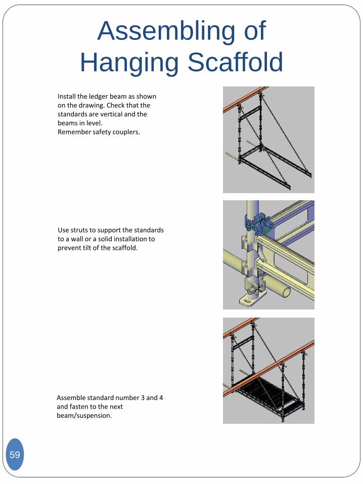
Install the ledger beam as shown on the drawing. Check that the standards are vertical and the beams in level. Remember safety couplers.
Use struts to support the standards to a wall or a solid installation to prevent tilt of the scaffold.
Assemble standard number 3 and 4 and fasten to the next beam/suspension.
Assembling of
Hanging Scaffold
60
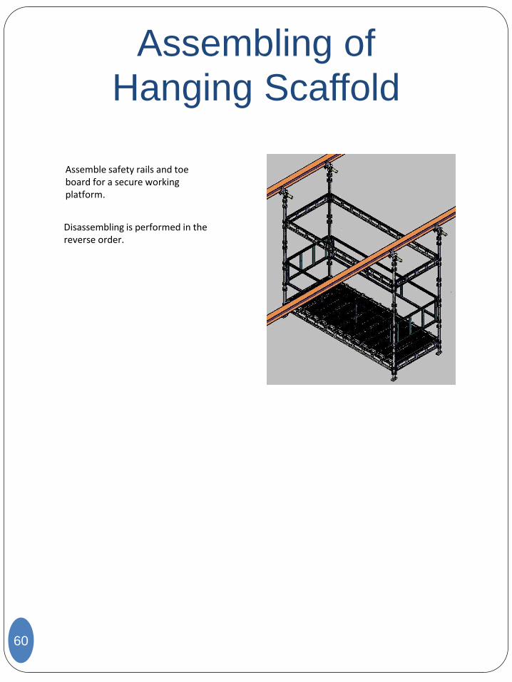
Assemble safety rails and toe board for a secure working platform.
Disassembling is performed in the reverse order.
Storebotn 73 N-5300 Kleppestø
Norway
Phone (+47) 5570 7054 Fax (+47) 5615 0201
[email protected] www.deltasystem.no