Assembly and operating instructions ProCal Calcium ... Calcium hypochlorite system Assembly and...
33
ProCal Calcium hypochlorite system Assembly and operating instructions A0973 Original Operating Instructions (2006/42/EC) Part number 985530 BA PC 001 05/12 EN Please carefully read these operating instructions before use! · Do not discard! The operator shall be liable for any damage caused by installation or operating errors! Technical changes reserved.
-
Upload
dinhnguyet -
Category
Documents
-
view
226 -
download
5
Transcript of Assembly and operating instructions ProCal Calcium ... Calcium hypochlorite system Assembly and...

ProCalCalcium hypochlorite system
Assembly and operating instructions
A0973
Original Operating Instructions (2006/42/EC)Part number 985530 BA PC 001 05/12 EN
Please carefully read these operating instructions before use! · Do not discard!The operator shall be liable for any damage caused by installation or operating errors!
Technical changes reserved.

985530, 1, en_GB
© 2012
ProMaqua GmbHMaaßstraße 32/169123 Heidelberg
email: [email protected]: www.promaqua.com
2

In order to make it easier to read, this document uses the maleform in grammatical structures but with an implied neutral sense. Itis aimed equally at both men and women. We kindly ask femalereaders for their understanding in this simplification of the text.
Read the following supplementary information in its entirety!The following are highlighted separately in the document:n Enumerated lists
Instructions
ð Results of the instructions
Information
This provides important information relating to the cor‐rect operation of the system or is intended to makeyour work easier.
Safety informationSafety information are provided with detailed descriptions of theendangering situation, see Ä Chapter 2.1 ‘Explanation of thesafety information’ on page 8
General non-discriminatory approach
Supplementary information
Supplemental instructions
3

Table of contents1 About this system.................................................................. 5
1.1 Summary of the ProCal components............................ 62 Safety and responsibility....................................................... 8
2.1 Explanation of the safety information............................ 82.2 Users' qualifications...................................................... 92.3 General safety notes................................................... 102.4 Correct and proper use............................................... 11
3 System overview and function............................................ 124 Control................................................................................ 145 Assembly............................................................................ 15
5.1 Storage and transport................................................. 155.2 Hydraulic Installation .................................................. 155.3 Electrical Installation................................................... 16
6 Commissioning................................................................... 196.1 Setting the local time and date................................... 216.2 Setting the duration and frequency of acid cleaning... 22
7 Maintenance....................................................................... 257.1 Troubleshooting.......................................................... 267.2 Disposal of used parts................................................ 28
8 Technical data..................................................................... 299 Appendix............................................................................. 31
9.1 Dimensions sheet....................................................... 319.2 Declaration of Conformity........................................... 32
10 Index................................................................................... 33
Table of contents
4

1 About this system
Calcium hypochlorite is the calcium salt of hypochlorous acid andhas the formula Ca(OCl)2.
The ProCal is used for disinfection of swimming pool water usingcalcium hypochlorite. The granulate metering unit of the ProCalcan produce a calcium hypochlorite solution from dry calciumhypochlorite. Low-chlorine disinfection solution is prepared with theintegrated full automatic metering unit and added to the swimmingpool water via a bypass line. Measuring and control units ensurecontrolled metering. Hence the disinfection of the pool water ofsmall to medium sized swimming pools can be carried out inaccordance with to DIN 19643-1.
Advantagesn Ready-to-use, pre-assembled calcium hypochlorite metering
systemn Operation through the production and metering of the disinfec‐
tion solution with a systemn Simple, quick assemblyn Minimal maintenance effortFeaturesn Disinfection using calcium hypochlorite with little effect on the
pH value and very low chlorate input.n Excellent safetyn Simple operationn Ready-to-use, complete calcium hypochlorite metering systemn Excellent disinfection effect
Application
About this system
5

1.1 Summary of the ProCal components
A0995
1.
2.
3.
6.
4.7.
5.
8.
9.
10.
11.
Fig. 1: Summary of the ProCal components1. Granulate storage tank2. Mixing chamber3. Feed pump4. Ball valve for flow adjustment5. Float flow meter6. Inlet-float valve
7. pH rinse/injection point8. Control with control cabinet9. Outlet DN 2510. Feed DN 2511. Overflow/drain DN 40
About this system
6

A1014
1.
2.
3.
Fig. 2: Granulate feeder1. Ball valve2. Angle piece for granulate feed3. Granulate feeder
About this system
7

2 Safety and responsibility
2.1 Explanation of the safety information
These operating instructions provide information on the technicaldata and functions of the product. These operating instructions pro‐vide detailed safety information and are provided as clear step-by-step instructions.The safety information and notes are categorised according to thefollowing scheme. A number of different symbols are used todenote different situations. The symbols shown here serve only asexamples.
DANGER!Nature and source of the dangerConsequence: Fatal or very serious injuries.Measure to be taken to avoid this dangerDanger!– Denotes an immediate threatening danger. If this is
disregarded, it will result in fatal or very seriousinjuries.
WARNING!Nature and source of the dangerPossible consequence: Fatal or very serious injuries.Measure to be taken to avoid this dangerWarning!– Denotes a possibly hazardous situation. If this is
disregarded, it could result in fatal or very seriousinjuries.
CAUTION!Nature and source of the dangerPossible consequence: Slight or minor injuries, mate‐rial damage.Measure to be taken to avoid this dangerCaution!– Denotes a possibly hazardous situation. If this is
disregarded, it could result in slight or minor inju‐ries. May also be used as a warning about materialdamage.
Introduction
Safety and responsibility
8

NOTICE!Nature and source of the dangerDamage to the product or its surroundingsMeasure to be taken to avoid this dangerNote!– Denotes a possibly damaging situation. If this is
disregarded, the product or an object in its vicinitycould be damaged.
Type of informationHints on use and additional informationSource of the information, additional measuresInformation!– Denotes hints on use and other useful information.
It does not indicate a hazardous or damaging sit‐uation.
2.2 Users' qualifications
WARNING!Danger of injury with inadequately qualified personnel!The operator of the plant / device is responsible forensuring that the qualifications are fulfilled.If inadequately qualified personnel work on the unit orloiter in the hazard zone of the unit, this could result indangers that could cause serious injuries and materialdamage.– All work on the unit should therefore only be con‐
ducted by qualified personnel.– Unqualified personnel should be kept away from
the hazard zone
Training Definition
Instructed personnel An instructed person is deemed to be a person who has been instructed and,if required, trained in the tasks assigned to him/her and possible dangers thatcould result from improper behaviour, as well as having been instructed in therequired protective equipment and protective measures.
Trained user A trained user is a person who fulfils the requirements made of an instructedperson and who has also received additional training specific to the systemfrom ProMinent or another authorised distribution partner.
Trained qualified per‐sonnel
A qualified employee is deemed to be a person who is able to assess thetasks assigned to him and recognize possible hazards based on his/hertraining, knowledge and experience, as well as knowledge of pertinent regula‐tions. The assessment of a person's technical training can also be based onseveral years of work in the relevant field.
Safety and responsibility
9

Training Definition
Electrician Electricians are deemed to be people, who are able to complete work on elec‐trical systems and recognize and avoid possible hazards independently basedon his/her technical training and experience, as well as knowledge of pertinentstandards and regulations.Electricians should be specifically trained for the working environment inwhich the are employed and know the relevant standards and regulations.Electricians must comply with the provisions of the applicable statutory direc‐tives on accident prevention.
Customer Service depart‐ment
Customer Service department refers to service technicians, who havereceived proven training and have been authorised by ProMinent to work onthe system.
Note for the system operatorThe pertinent accident prevention regulations, as wellas all other generally acknowledged safety regulations,must be adhered to!
2.3 General safety notes
WARNING!Live parts!Possible consequence: Fatal or very serious injuries– Measure: Before opening the housing or before
carrying out installation work, ensure the devicesare voltage-free.
– Disconnect damaged, defective or tampered-withdevices from the power supply.
WARNING!Danger from hazardous substances!Possible consequence: Fatal or very serious injuries.Please ensure when handling hazardous substancesthat you have read the latest safety data sheets pro‐vided by the manufacture of the hazardous substance.The actions required are described in the safety datasheet. Check the safety data sheet regularly andreplace, if necessary, as the hazard potential of a sub‐stance can be re-evaluated at any time based on newfindings.The system operator is responsible for ensuring thatthese safety data sheets are available and that theyare kept up to date, as well as for producing an associ‐ated hazard assessment for the workstations affected.
Safety and responsibility
10

WARNING!Unauthorised access!Possible consequence: Fatal or very serious injuries.– Measure: Ensure that there can be no unauthor‐
ised access to the device
WARNING!Operating faults!Possible consequence: Fatal or very serious injuries.– The unit should only be operated by adequately
qualified and technically expert personnel– Please also observe the operating instructions for
controllers and fittings and any other componentgroups, such as sensors, sample water pumps ...
– The operator is responsible for ensuring that per‐sonnel are qualified
2.4 Correct and proper use
NOTICE!Correct and proper useThe device is intended for the dissolving of calciumhypochlorite granulate in swimming pool water and formetering it into a swimming pool.The unit may only be used in accordance with thetechnical details and specifications provided in thisoperating manual and in the operating manuals for theindividual components (such as, for example, sensors,fittings, calibration devices, metering pumps etc.).Any other uses or modifications are prohibited.
Safety and responsibility
11

3 System overview and function
A0995
1.
2.
3.
6.
4.7.
5.
8.
9.
10.
11.
Fig. 3: System overview and function
number Part number Description Specification
1 - Granulate storage tank Capacity: 40 kg, material: PE white
2 - Mixing chamber Volume: 10 litre, Material: PE white
3 1040730 Feed pump Lowara, operating voltage 240 VAC
4 1024534 Ball valve 25 mm, PVC, FPM seal
5 1008584 Float flow meter 300 - 3000 l/h
6 - Inlet-float valve comprising 6a, 6b, 6c
6a 1040733 Float switch
6b 1040754 Flow controller
6c 1040755 Valve
7 924594 pH rinse/injection point Injection point - sulphuric acid for acid flushing,PVDF/PTFE
8 1040758 Operating unit Contains the system control and electrics
9 - Outlet DN25
10 - Feed DN25
11 - Overflow/drain DN40
System overview and function
12

A1014
1.
2.
3.
Fig. 4: System overview and function
number Part number Description Specification
1 1040731 Ball valve Ball valve with bracket (1a)
1a 1040732 Ball valve bracket
2 - Metering pipe
3 1040756 Feeder Operating voltage: 24 VDC, frequency 3500 rpm
System overview and function
13

4 Control
A0996
1 2
3
4
5
6
Fig. 5: ProCal control panel1. Feed pump operating indicator2. Granulate feeder operating indicator3. Pushbutton with operating indicator [Acid cleaning]4. Light indicators for the fault messages5. Fault acknowledgement button6. Main switch for [Test operation], [Off], [Automatic]
Lettering Description
[PUMP] Feed pump operating indicator
[FEEDER] Granulate feeder operating indicator
[TEST] Test operation: System running with 100 % output, no control
[OFF] The system is completely switched off, but not isolated from the mains voltage
[AUTO] Automatic: System runs according to the input signal of the external control (e.g.DULCOMARIN® II ...)
[ACID WASH] Pushbutton with operating indicator: System continues running, additionally acidis metered into the system for cleaning.
[FEEDER FAULT] Indicator light: Feeder has a fault and is not transporting any granulate
[FLOW FAULT] Indicator light: No or too low water flow through the ProCal
[HIGH LEVEL FAULT] Indicator light flashes: Mixing chamber over full.
Indicator light illuminated continuously: The external leakage sensor is alarmed.Feeder stops
[ALARM RESET] Pushbutton: All faults are cleared.
Control
14
5 Assembly
n User qualification, mechanical and hydraulic installation:trained qualified personnel, see Ä Chapter 2.2 ‘Users' qualifi‐cations’ on page 9
n User qualification, electrical installation: Electrical technician,see Ä Chapter 2.2 ‘Users' qualifications’ on page 9
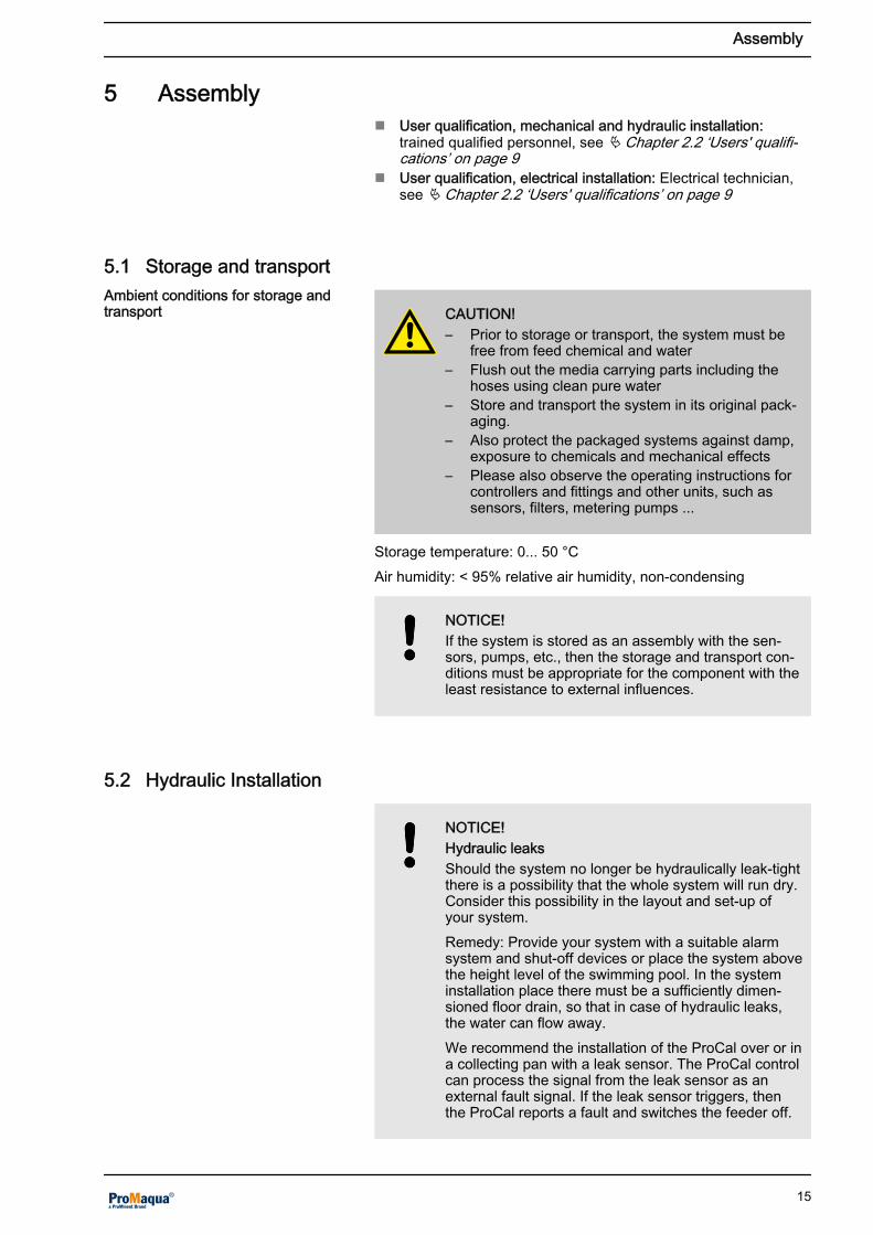
5.1 Storage and transport
CAUTION!– Prior to storage or transport, the system must be
free from feed chemical and water– Flush out the media carrying parts including the
hoses using clean pure water– Store and transport the system in its original pack‐
aging.– Also protect the packaged systems against damp,
exposure to chemicals and mechanical effects– Please also observe the operating instructions for
controllers and fittings and other units, such assensors, filters, metering pumps ...
Storage temperature: 0... 50 °CAir humidity: < 95% relative air humidity, non-condensing
NOTICE!If the system is stored as an assembly with the sen‐sors, pumps, etc., then the storage and transport con‐ditions must be appropriate for the component with theleast resistance to external influences.
5.2 Hydraulic Installation
NOTICE!Hydraulic leaksShould the system no longer be hydraulically leak-tightthere is a possibility that the whole system will run dry.Consider this possibility in the layout and set-up ofyour system.Remedy: Provide your system with a suitable alarmsystem and shut-off devices or place the system abovethe height level of the swimming pool. In the systeminstallation place there must be a sufficiently dimen‐sioned floor drain, so that in case of hydraulic leaks,the water can flow away.We recommend the installation of the ProCal over or ina collecting pan with a leak sensor. The ProCal controlcan process the signal from the leak sensor as anexternal fault signal. If the leak sensor triggers, thenthe ProCal reports a fault and switches the feeder off.
Ambient conditions for storage andtransport
Assembly
15

12.
6.
7.
4.
3.5.
2.
1.
11.
9.
10.
8.
A0931
6.
Fig. 6: Hydraulic installation circuit diagram1. Swimming pool2. Circulating pump3. Filter inlet4. Filter5. Filter outlet6. Stopcock
7. Outlet / overflow (32 mm PVC)8. Inlet (25 mm PVC) / nominal 3000 l/h at 0.8
bar9. Outlet (25 mm PVC)10. Start / stop control by the controller (e.g. DUL‐
COMARIN® II ...)11. Control of the metering pump for acid cleaning12. Mains connection 240 VAC
5.3 Electrical Installation
n User qualification, electrical installation: Electrical technician,see Ä Chapter 2.2 ‘Users' qualifications’ on page 9
WARNING!Live parts!Possible consequence: Fatal or very serious injuries– Measure: Before opening the housing or before
carrying out installation work, ensure the devicesare voltage-free.
– Disconnect damaged, defective or tampered-withdevices from the power supply.
Assembly
16

A0932
Fig. 7: Electrical installation / original drawing is E01I. 24 hour timer (optional)II. Circulating pumpIII. Acid metering pump
IV. Collective alarmV. Switch contact of the acid metering pumpVI. Feeder with 24 VDC
Assembly
17

1.
2.
3.
4.
5.
6.
7.
8.
A0933
16.
15.
14.
13.
12.
11.
10.
9.
Fig. 8: Electrical installation / original drawing is E021. Circulating pump, relay and light2. Feeder, relay and light3. Acid metering pump, relay4. Collective alarm, relay5. Circulating pump, indicator light, no flow6. Indicator light, high liquid level7. Feeder, fault indicator light8. Indicator light, acid introduction
9. Remote starter10. Contact to the controller (e.g. D1C)11. Switch, actuator limit12. Switch, high liquid level13. Switch, circulating pump flow14. Contact, acid introduction timer (optional)15. Alarm reset16. Operating mode selection switch
If connected to a D1C, XR1 or XR2 can be useddependent upon the relay action.
Assembly
18
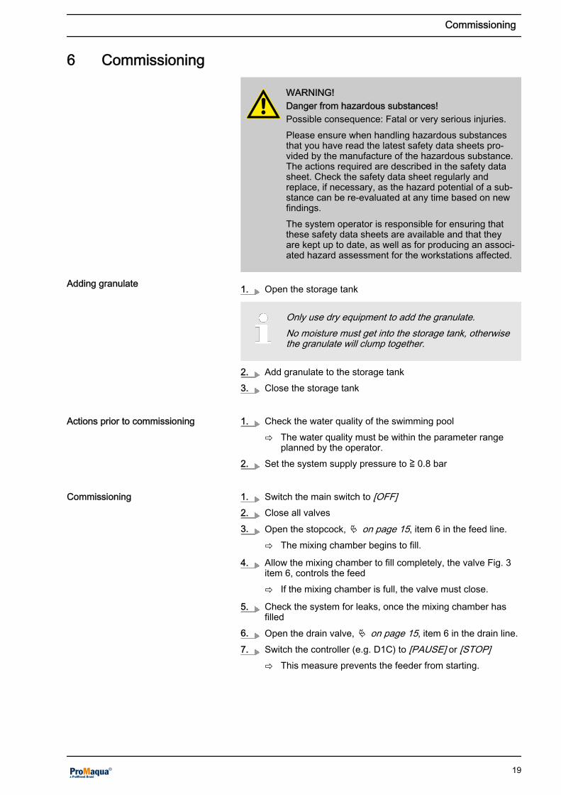
6 Commissioning
WARNING!Danger from hazardous substances!Possible consequence: Fatal or very serious injuries.Please ensure when handling hazardous substancesthat you have read the latest safety data sheets pro‐vided by the manufacture of the hazardous substance.The actions required are described in the safety datasheet. Check the safety data sheet regularly andreplace, if necessary, as the hazard potential of a sub‐stance can be re-evaluated at any time based on newfindings.The system operator is responsible for ensuring thatthese safety data sheets are available and that theyare kept up to date, as well as for producing an associ‐ated hazard assessment for the workstations affected.
1. Open the storage tank
Only use dry equipment to add the granulate.No moisture must get into the storage tank, otherwisethe granulate will clump together.
2. Add granulate to the storage tank3. Close the storage tank
1. Check the water quality of the swimming pool
ð The water quality must be within the parameter rangeplanned by the operator.
2. Set the system supply pressure to ≧ 0.8 bar
1. Switch the main switch to [OFF]2. Close all valves3. Open the stopcock, Ä on page 15, item 6 in the feed line.
ð The mixing chamber begins to fill.
4. Allow the mixing chamber to fill completely, the valve Fig. 3item 6, controls the feed
ð If the mixing chamber is full, the valve must close.
5. Check the system for leaks, once the mixing chamber hasfilled
6. Open the drain valve, Ä on page 15, item 6 in the drain line.7. Switch the controller (e.g. D1C) to [PAUSE] or [STOP]
ð This measure prevents the feeder from starting.
Adding granulate
Actions prior to commissioning
Commissioning
Commissioning
19

8.Upon starting operation an alarm [Flow fault]may appear. Clear the alarm by pressing the[ALARM RESET] button. This may have to berepeated several times until a uniform flow of3000 l/h has been set.
Switch the main switch to [AUTO]ð The feed pump starts.
9. During operation with low back pressure, the flow controlvalve in the area of the feed pump outlet may cause a highfrequency noise. You can prevent this by carefully adjustingthe back pressure using the outlet shut-off valve until thenoise disappears. However this must not cause the flow tofall below 3000 l/h
ð The level in the mixing chamber must automatically setitself to a level beneath the overflow. An incorrect oroscillating level is typical for a supply pressure < 0.8 bar.Please check the system supply pressure and set it cor‐rectly to ≧ 0.8 bar.
10. Now check all the system lines for leaks.
ð System operation should only be started once all thelines are leak-tight.
Observe the instructions of the chemical manufacturer.
11. Now fill the system with calcium hypochlorite granulate12. Set the controller (e.g. D1C) to 100 % feed rate for the
ProCal. The feeder must feed continuously
ð This ensures all feed lines are filled with granulate. Thiscan be seen in the transparent parts of the feed line.
Daily checking of the granulate level in the storagetank should be carried out until a consumption patternbecomes apparent.
13. If necessary, fill the storage tank14. Set the controller, e.g. with the D1Cb at output XR1, to a
cycle time ≧ 30 seconds. This signal directly controls thefeeder running time
Commissioning
20

Factory settingThe factory setting of the angle piece is horizontal.
Before you turn the feed line, close the shut-off valveof the storage tank and ensure that the connectordirectly under this shut-off valve is correctly fitted.After you have carried out all settings and checks, youcan open the shut-off valve.
15. Set the feed rate by turning the 45° angle piece. The adjust‐ment is made by turning the angle piece towards its hori‐zontal positionn Angle piece horizontal (90 °) = maximum feed raten Angle piece vertically upright (0 °) = minimum feed rate
Tank size (m3) Cycle time at the con‐troller output
Angle pieceadjustment
Remarks
10 ... 30 ≧ 30 ... 60 seconds 0 ° After commissioning, the chlorine con‐tent in the water must be checked atshort intervals. Adjust the position of theangle piece based on the results so col‐lected. In this way the system feed rateis optimally set for the overall system.
30 ... 50 1 ... 3 minutes. 30 °
> 50 3 ... 5 minutes. 45 °
6.1 Setting the local time and date
Personnel qualificationThis work requires accessing of the electrical controlpanel and must not be carried out by unqualified users,see Ä Chapter 2.2 ‘Users' qualifications’ on page 9.
1. Press the key2. Press the key, until [SET] appears on the display3. Press the key4. Press the key, until [SET CLOCK] appears on the display5. Press the key6. Press the or key to set the correct weekday.7. Press the key8. Press the or key to set the first hour figure (0 ... 9)9. Press the key10. Press the or key to set the second hour figure (0 ... 9)11. Press the key12. Press the or key to set the first minute figure (0 ... 9)13. Press the key14. Press the or key to set the second minute figure (0 ... 9)15. Press the key
Feed rate
Commissioning
21

16. Press the or key to set the first year figure (0 ... 9)17. Press the key18. Press the or key to set the second year figure (0 ... 9)19. Press the key20. Press the or key to set the third year figure (0 ... 9)21. Press the key22. Press the or key to set the fourth year figure (0 ... 9)23. Press the key24. Press the or key to set the first month figure (0 ... 9)25. Press the key26. Press the or key to set the second month figure (0 ... 9)27. Press the key28. Press the or key to set the first day figure (0 ... 9)29. Press the key30. Press the or key to set the second day figure (0 ... 9)31. Press the key32. Press the key33. Press the key34. Press the key
ð You have successfully entered the current date and timein the control.
6.2 Setting the duration and frequency of acid cleaning
Personnel qualificationThis work requires accessing of the electrical controlpanel and must not be carried out by unqualified users,see Ä Chapter 2.2 ‘Users' qualifications’ on page 9.
1. Press the key2. Press the key3. Press the key
ð until the [B5] menu is displayed.
4. Press the key5. Press the , and key to set the weekday on which acid
is to be metered. The initial setting is every day of the week.6. Press the key
ð The start time for acid cleaning starts to flash. The initialsetting is 23.00 hours.
7. Press the or key to set the first hour figure (0 ... 9)8. Press the key9. Press the or key to set the second hour figure (0 ... 9)10. Press the key
Commissioning
22

11. Press the or key to set the first minute figure (0 ... 9)12. Press the key13. Press the or key to set the second minute figure (0 ... 9)14. Press the key
ð The end time for acid cleaning starts to flash. The initialsetting is 23.01 hours.
15. Press the or key to set the first hour figure (0 ... 9). Thiswill be the same as the start time.
16. Press the key17. Press the or key to set the second hour figure (0 ... 9).
This will be the same as the start time.18. Press the key19. Press the or key to set the first minute figure (0 ... 9).
This will be the same as the start time.20. Press the key21. Press the or key to set the second minute figure (0 ...
9). This will be the same as the start time, plus 1 minute22. Press the key23. Press the key
ð until the [B7] menu is displayed.
24. Press the key
ð The pre-rinse time is displayed. The initial setting is 5minutes.
25. Press the or key to set the first minute figure (0 ... 9)26. Press the key27. Press the or key to set the second minute figure (0 ...
9).28. Press the key29. Press the key
ð until the [B8] menu is displayed.
30. Press the key
ð The dosing time of the rinsing is displayed. The initial set‐ting is 6 minutes (5 minutes pre-rinse time and 1 minutedosing time).
31. Press the or key to set the first minute figure (0 ... 9)32. Press the key33. Press the or key to set the second minute figure (0 ...
9).34. Press the key35. Press the key
ð until the [B9] menu is displayed.
36. Press the key
ð The duration of the rinsing time is displayed. The initialsetting is 11 minutes (5 minutes pre-rinse time plus 1minute dosing time plus 5 minutes rinsing time).
37. Press the or key to set the first minute figure (0 ... 9)
Commissioning
23

38. Press the key39. Press the or key to set the second minute figure (0 ...
9).40. Press the key41. Press the key42. Press the key
Commissioning
24
7 Maintenance
n User qualification: trained user, see Ä Chapter 2.2 ‘Users'qualifications’ on page 9
Maintenance takes place every three months or ear‐lier, if the application makes this necessary.
1. Set the selection switch of the control to [OFF]2. Close the stopcocks upstream and downstream of the filter3. Open the drainage cock in the bottom of the filter4. Unscrew the filter housing
ð Remove the filter.
5. Clean the filter using a brush or running water6. Place the filter in the filter housing and retighten the filter
housing.7. Close the drainage cock in the bottom of the filter8. Open the stopcocks upstream and downstream of the filter9. Set the selection switch of the control to [AUTO]
1. Switch the controller (e.g. D1C) to [PAUSE]ð The feeder stops.
2. Allow the feed pump to run in order to flush the mixingchamber with the water flow
3. Switch the controller (e.g. D1C) to [CONTROL]ð The feeder starts.
1. Set the selection switch of the control to [OFF]2. Close the stopcock3. Open the ball valve
ð The mixing chamber empties, however a residual amountof water remains in the mixing chamber.
4. Close the ball valve
You require a container of sufficient capacity for 2 minutes contin‐uous filling.1. Weigh the empty container2. Place the container beneath the granulate outlet3.
During this procedure also observe the operatinginstructions for your controller.
Set the controller (e.g. D1C) to 1 minute at 100 % capacity ofthe feeder
4. End the feed process once one minute has elapsed
(Optional) cleaning the filter
Flushing the system
Emptying the mixing chamber
Checking the feed rate
Maintenance
25

5. Weigh the granulate-filled container6. Check whether the weight of the fed granulate quantity corre‐
sponds to the quantity necessary for your process7. If necessary, adjust the feed rate, see Ä ‘Commissioning’
on page 19 and repeat steps 2 - 68. As soon as the desired feed rate is achieved, return the
system and controller to normal operation
1. Set the selection switch of the control to [OFF]2. Close the feeder stopcock3. Unscrew the granulate feed line from the stopcock4. Clean the granulate feed line
The granulate feed line must be completely drywhen reconnected.
5. Refit the granulate feed line6. Open the feeder stopcock7. Set the selection switch of the control to [AUTO]
7.1 Troubleshooting
n User qualification: trained user, see Ä Chapter 2.2 ‘Users'qualifications’ on page 9
WARNING!Danger from hazardous substances!Possible consequence: Fatal or very serious injuries.Please ensure when handling hazardous substancesthat you have read the latest safety data sheets pro‐vided by the manufacture of the hazardous substance.The actions required are described in the safety datasheet. Check the safety data sheet regularly andreplace, if necessary, as the hazard potential of a sub‐stance can be re-evaluated at any time based on newfindings.The system operator is responsible for ensuring thatthese safety data sheets are available and that theyare kept up to date, as well as for producing an associ‐ated hazard assessment for the workstations affected.
Cleaning the granulate feed lines
Maintenance
26

Fault messages
Fault message Cause
[FEEDER FAULT] Granulate feeder is faultyn Running time exceeded
– Acknowledge the fault message and restart the systemn Granulate feeder defective
– Contact customer service
[FLOW FAULT] Flow too lown Is the feed pump running?n Are all ball valves in the feed and drain lines open?n Is there free flow in all feed and drain lines and are they free
from blockages?
[LEAKAGE / HIGH LEVEL FAULT ](Indicator flashes)
Mixing chamber has reached maximum leveln Is the feed pump transporting away sufficient solution?n Is the float valve closing correctly?n Is there free flow in all feed and drain lines and are they free
from blockages?
[LEAKAGE / HIGH LEVEL FAULT ] Mixing chamber has exceeded maximum leveln Only enter the room wearing protective equipment
– Calcium hypochlorite has escaped, observe the safetydata sheet
n Observe the operational instructions for an accident involvingcalcium hypochlorite
We recommend installation of a suitable gas detector. In thisrespect, note the current national regulations and legal standardswhich apply in your country
As soon as the fault is cleared, you can clear the faultmessage with the [ALARM RESET] key.
CAUTION!Controller faultsCause: The controller signal defines the chlorine quan‐tity added to the swimming pool water. If faults occur inthe measuring and control technology, a too highdosing requirement is applied to the ProCal whichresults in overdosing of chlorine.Consequence: Skin and airway irritation resulting fromthe overdosing of chlorine.Measure: You can set the maximum ProCal runningtime in the ProCal control so that the dosing quantity islimited. A dangerous concentration is then impossible.Additionally you can configure the controller so that if asample water fault occurs, metering is stopped and analarm triggered.
Maintenance
27

Fault description Cause Remedy
No chlorine in the water No granulate in the storagetank
Adding granulate
Stopcock in the metering lineclosed
Open stopcock
Too high water level in themixing chamber
A process component is faulty Check the water pressure. Setpoint ≧ 0.8 barCheck the filterCheck the flow controllerCheck the feed and drain lines for blockagesCheck the float valve
No water flow (float DFM) Feed pump defective Check the feed pump
Outlet blocked Check the outlet for blockages
Feeder fault Feed line to the feeder isblocked
Check and clean
No granulate in the storagetank
Adding granulate
Storage tank outlet blocked Check and clean
Controller defective See the controller operating instructions Afault in the control can lead to over andunder-dosing.
7.2 Disposal of used parts
n Users' qualification: instructed persons, see Ä Chapter 2.2‘Users' qualifications’ on page 9
NOTICE!Regulations governing disposal of used parts– Note the current national regulations and legal
standards which apply in your country
ProMinent Dosiertechnik GmbH, Heidelberg will take back decon‐taminated used devices providing that they are covered by ade‐quate postage.
Maintenance
28

8 Technical data
Technical datan Granulate metering: max. [Platzhalter] for chlorine metering up
to no more than 4 kg/hn Solution concentration: max. 1.4 g/l at flow = 3 m³/hn Granulate specification: DIN EN 15796n Process water flow: nom. 3 m³/h
Electrical datan Supply voltage: 240VAC / 50Hz (1/N/PE)n Pre-fuse max. 16 An Power consumption: max. 1 kWn Degree of protection control cabinets: IP65
Switch inputs:n 3 x potential-free contacts, contact loading: 24 V DC, max. 10
mA– 1 x controller input: Pulse-pause signal with any pulse ele‐
mentary period (*)– 1 x external leak sensor– 1 x pause input, external release
n (*) The suitable pulse elementary period must match the con‐trol path, in general this must be chosen so that it is shorter forsmaller pools than for larger pools. A pulse elementary periodof 30 to 60 seconds is suitable for most swimming pools, how‐ever an optimisation is only possible in the overall context ofthe pool hydraulics.
Switching power outputs:n 2 x potential-free relay contacts: max. 230V, 5A
– 1 x operating report: Contact type N.O.– 1 x fault message: Contact type N.C.
Ambient conditionsn Note the current national regulations and legal standards which
apply in your countryn Ensure a vibration, shock and oscillation-free set-upn Ensure protection against climatic influences is providedn Ensure protection against tampering is provided, e.g. separate
lockable room with corresponding signagen Ensure there is a clear floor drain in the installation room. The
capacity of the floor drain must be greater that the maximumpossible water quantity
The system is not suitable for mobile operation.Storage and transport: Temperature: -10 °C to +70 °C Humidity: <95 % relative air humidity, non-condensingOperation: Temperature: +10 °C to +40 °C Humidity: < 95 % rela‐tive air humidity, non-condensing.
Technical data
29

Description Values and conditions
Empty weight: 68 kg
Transport weight incl. Euro-pallet: 88 kg
Weight when operating: approx. 125kg
System dimensions: 900 mm x 1100 mm x 500 mm (W x H x D)
Transport dimensions on Euro-pallet:
1200 mm x 800 mm x 1270 mm (L x W x H)
Installation dimensions: Width: 900 mm ➨ right space requirement for lines approx. 50 cm
Height: 1100 mm ➨ clearance space requirement above for filling atleast 70 cm.
Depth: 500 mm ➨ in front of the system at least 1 m clear width foroperation and maintenance
Water supply: Connector DN25, max. priming pressure [Platzhalter}
Solution drain: Connector DN25, max. back pressure 2 bar
Overflow/channel: Connector DN 40, at atmospheric pressure/free flow in closed channelwith odour trap/siphon trap
Dimensions and weights:
Technical data
30

9 Appendix
9.1 Dimensions sheet
6622
0 360
500
1100
100
1058A1015
Fig. 9: All values given in millimetres
Appendix
31

9.2 Declaration of Conformity
Fig. 10: Declaration of Conformity
Appendix
32
10 Index
AAlarm system....................................................... 15Ambient conditions............................................... 15BBack pressure...................................................... 19CCalcium hypochlorite.............................................. 5Calcium salt of hypochlorous acid.......................... 5Checking the feed rate......................................... 25Chemical manufacturer........................................ 19Cleaning the granulate feed lines........................ 26Clean the filter...................................................... 25Clearing a fault message..................................... 27Control.................................................................. 14Control panel........................................................ 14DDisinfection using calcium hypochlorite................. 5EElectrical data....................................................... 29Emptying the mixing chamber.............................. 25Entire system runs dry......................................... 15FFault messages.................................................... 27Feed pump operating indicator............................ 14Feed rate.............................................................. 21Floor drain............................................................ 15Flushing the system............................................. 25GGeneral non-discriminatory approach.................... 3Granulate feeder.................................................... 7Granulate feeder operating indicator................... 14HHydraulic installation circuit diagram ................... 16LLeakage sensor.................................................... 16Nnon-discriminatory approach.................................. 3OOperating voltage................................................. 13PPart number......................................................... 12ProCal components................................................ 6
QQuestion: Do I require a leak sensor?................. 16Question: How can I store and transport thesystem?................................................................ 15Question: How do you clean a granulate feedline?...................................................................... 26Question: How do you clear a fault message?... . 27Question: How is commissioning undertaken?.... 19Question: How is installation carried out?............ 15Question: How is the feed rate checked?............ 25Question: How is the filter cleaned?.................... 25Question: How is the granulate added?............... 19Question: How is the mixing chamber emptied?.. 25Question: What actions must be carried outprior to commissioning?....................................... 19Question: What ambient conditions must beobserved for storage and transport?.................... 15Question: What are the advantages of thesystem?.................................................................. 5Question: What are the features of the system?.... 5Question: What is the system flushing duration?. 25Question: What is the system used for?................ 5Question: What operating elements does thecontrol have?........................................................ 14Question: What should be considered as pro‐viding protection against hydraulic leaks?........... 15Question: What sort of fault messages arethere and what information do they give?............ 27Question: Which components make up thesystem?................................................................ 12Question: Who carries the installation out?......... 15SSafety information.................................................. 8Shut-off devices................................................... 15Storage................................................................. 15System supply pressure....................................... 19TTank shut-off valve............................................... 19Transport.............................................................. 15UUsers' qualifications............................................... 9
Index
33