Aspect Studio - · PDF file800xA - Engineering System Version 4.1 Aspect Studio. NOTICE ......
342
Industrial IT 800xA - Engineering System Version 4.1 Aspect Studio
Transcript of Aspect Studio - · PDF file800xA - Engineering System Version 4.1 Aspect Studio. NOTICE ......
IndustrialIT800xA - Engineering
System Version 4.1
Aspect Studio

IndustrialIT800xA - Engineering
System Version 4.1
Aspect Studio
NOTICEThe information in this document is subject to change without notice and should not beconstrued as a commitment by ABB. ABB assumes no responsibility for any errors thatmay appear in this document.
In no event shall ABB be liable for direct, indirect, special, incidental or consequentialdamages of any nature or kind arising from the use of this document, nor shall ABB beliable for incidental or consequential damages arising from use of any software or hard-ware described in this document.
This document and parts thereof must not be reproduced or copied without written per-mission from ABB, and the contents thereof must not be imparted to a third party nor usedfor any unauthorized purpose.
The software or hardware described in this document is furnished under a license andmay be used, copied, or disclosed only in accordance with the terms of such license.
This product meets the requirements specified in EMC Directive 89/336/EEC and in LowVoltage Directive 72/23/EEC.
Copyright © 2003-2005 by ABB. All rights reserved.
Release: June 2005Document number: 3BSE032792R4101
TRADEMARKSAll rights to trademarks reside with their respective owners.
TABLE OF CONTENTS
About This BookGeneral ............................................................................................................................11
Intended User...................................................................................................................12
Document Conventions ...................................................................................................12
Use of Warning, Caution, Information, and Tip Icons ....................................................14
Terminology.....................................................................................................................15
Applicable Specifications ................................................................................................18
Related Documentation ...................................................................................................19
Section 1 - IntroductionProduct Overview............................................................................................................21
Product Scope.......................................................................................................22
What You Can Do with the Aspect Studio Toolbox.............................................23
What’s New in This Release ................................................................................31
Product Release History .......................................................................................31
Prerequisites and Requirements ......................................................................................34
Section 2 - InstallationReinstall, uninstall and change.............................................................................40
Start-up and shut-down Procedures.................................................................................41
Verification of the Installation .........................................................................................42
Section 3 - Configuration ................................................................................43
3BSE032792R4101 5
Table of Contents
Section 4 - OperationOperating Overview ........................................................................................................45
The Product Structure...................................................................................................... 45
Getting Started................................................................................................................. 47
Prerequisites.........................................................................................................47
Work Flow Examples ...................................................................................................... 47
Adding a New System Extension Component.....................................................47
Build of a Product Version...................................................................................52
Section 5 - The Environment Setup ToolWhat you can do with the Environment Setup tool ........................................................ 57
Getting Started................................................................................................................. 58
Tutorial ............................................................................................................................ 59
User Interfaces................................................................................................................. 64
The initial/start up dialog boxes........................................................................... 64
The Environment Setup dialog box ..................................................................... 69
Editing the development environment .ini file .................................................... 77
Section 6 - The Aspect Objects AppWizard and the Class WizardWhat you can do with the Aspect Objects AppWizard................................................... 83
The Aspect Objects AppWizard User Interface .............................................................. 84
Aspect Objects AppWizard - Step 1 of 2 .............................................................86
Aspect Objects AppWizard Step 2 of 2 ............................................................... 87
What you can do with the Class Wizard ......................................................................... 90
The Class Wizard User Interface..................................................................................... 90
Adding an Aspect Data ASO ............................................................................... 91
Adding an Aspect View ASO ............................................................................ 100
Adding an Aspect Page ASO............................................................................. 102
Adding an Aspect Verb ASO ............................................................................. 103
6 3BSE032792R4101
Table of Contents
Section 7 - The Build ManagerWhat you can do with the Build Manager.....................................................................105
Getting Started...............................................................................................................106
Tutorial ..........................................................................................................................107
User Interface ................................................................................................................ 111
The Initial/start up Dialog Box ..........................................................................112
The Build Manager Dialog Box .........................................................................113
The VSS Related Branch ...................................................................................115
The Project Related Branch ...............................................................................136
The Build Related Branch ..................................................................................165
The Schedule Related Branch ............................................................................193
Section 8 - The AutoBuild ToolSetting up the AutoBuild Add-ins .................................................................................198
Configure AutoBuild .....................................................................................................200
Build Visual Studio Projects ..............................................................................200
Create Windows Installer MSM Files ................................................................203
Run AutoBuild...............................................................................................................207
AutoBuild Log Viewer .......................................................................................210
QuickBuild ....................................................................................................................211
Section 9 - The PostScript GeneratorGetting Started...............................................................................................................213
User Interface ................................................................................................................214
Section 10 - The Product PackagerWhat You Can Do with the Product Packager...............................................................217
Setting of version on Service Packs and Patches ...............................................217
Getting Started...............................................................................................................222
Tutorial 1 - Creation of a Product Distribution Package ...............................................222
Tutorial 2 - Creation of a Service Pack .........................................................................237
Tutorial 3 - Creation of a Patch Pack.............................................................................245
Tutorial 4 - Creation of an Extension Pack ...................................................................248
3BSE032792R4101 73BSE032792R4101 7
Table of Contents
Tutorial 5 - Create a Distribution in Batch Mode ......................................................... 254
Procedures ..................................................................................................................... 255
Install, Re-install and Un-install a Distribution ................................................. 256
Installation through Internet............................................................................... 257
Silent Installation ............................................................................................... 258
Create a Service Pack ........................................................................................ 259
Install a Service Pack......................................................................................... 259
Create an Extension Pack .................................................................................. 260
Install an Extension Pack................................................................................... 260
Customize the Autoplay Dialog .................................................................................... 262
User Interfaces............................................................................................................... 268
The Product Packager User Interface ................................................................ 268
The Service Pack Builder User Interface........................................................... 288
The Extension Pack Builder User Interface....................................................... 292
Section 11 - The Product ViewerWhat you can do with the Product Viewer.................................................................... 293
Getting Started............................................................................................................... 293
How to use the Product Viewer..................................................................................... 294
Product Viewer User Interface ...................................................................................... 295
Section 12 - MaintenancePreventive Maintenance ................................................................................................ 303
Error Messages.............................................................................................................. 303
Error Messages from the Product Packager....................................................... 303
Appendix A - Build ABC File ConfigurationFunctional Overview..................................................................................................... 305
General .......................................................................................................... 305
The Development Structure ............................................................................... 306
The Build Files................................................................................................... 307
8 3BSE032792R4101
Table of Contents
Appendix B - Strong Name in Aspect StudioStrong Name and Interoperability .................................................................................325
Strong Name.......................................................................................................325
Interoperability ...................................................................................................326
Strong Name Requirements ...............................................................................326
Strong Name and Interoperability in the Aspect Studio Tools ......................................326
Environment Setup Tool.....................................................................................327
Build Manager Tool ...........................................................................................327
Auto Build ..........................................................................................................329
Does it Work? ................................................................................................................330
Re-signing Assemblies ..................................................................................................331
Create a Package of the Product for Distribution ..........................................................333
Problems ........................................................................................................................333
Same Keys - Different Products.........................................................................333
Old Products - No Keys .....................................................................................334
A Final Word .................................................................................................................335
INDEX ........................................................................................................................337
3BSE032792R4101 93BSE032792R4101 9
Table of Contents
10 3BSE032792R4101

About This Book
GeneralThis guide is mainly intended for those who are going to install, configure, use/operate, and/or maintain the Aspect Studio software package.
For an introduction to Aspect Studio, please read Section 1, Introduction and Section 12, Maintenance.
For installation and maintenance of the Aspect Studio - normally system administrators - please read, in the first place, Section 1, Introduction,Section 2, Installation and Section 12, Maintenance.
And if you are going to use Aspect Studio - normally application developers and configuration managers - please read, in the first place, Section 1, Introduction and sections 4 to 11, and also, when some problem arises, Section 12, Maintenance.
Section 1, Introduction
A brief description of the Aspect Studio tools and the requirements that have to be met to install and use the tools. It is on the first hand intended as an introduction for those who are going to use Aspect Studio, but can also be read by those who just want an introduction to the product.
Section 2, Installation
Describes, step by step, how to install Aspect Studio. It also informs you what other software packages you have to install, prior to those two.
3BSE032792R4101 11
Intended User About This Book
Section 3, Configuration
Section 3 describes briefly how to configure a computer for development of an Aspect Studio compliant product by using the Aspect Studio "Environment Setup" tool.
Sections 4 to section 12
Discusses all the details concerning usage of all of the available Aspect Studio tools. It contains, for example, tutorials and detailed descriptions of the Aspect Studiouser interfaces.
Section 12, Maintenance
Describes mainly maintenance, error messages, from the different Aspect Studio tools, and trouble shooting.
Intended User This guide is mainly intended for those who are going to install, configure, use/operate, and/or maintain the Aspect Studio software package.
The reader should have experience with process control systems and Microsoft® Windows® operating systems. In general, Microsoft Windows functions are not described in this instruction.
Document ConventionsThe following conventions are used for the presentation of material:
• The words in names of screen elements (for example, the title in the title bar of a window, the label for a field of a dialog box) are initially capitalized.
• Capital letters are used for the name of a keyboard key if it is labeled on the keyboard. For example, press the ENTER key.
• Lowercase letters are used for the name of a keyboard key that is not labeled on the keyboard. For example, the space bar, comma key, and so on.
12 3BSE032792R4101
About This Book Document Conventions
• Press CTRL+C indicates that you must hold down the CTRL key while pressing the C key (to copy a selected object in this case).
• Press ESC E C indicates that you press and release each key in sequence (to copy a selected object in this case).
• The names of push and toggle buttons are boldfaced. For example, click OK.
• The names of menus and menu items are boldfaced. For example, the File menu.
– The following convention is used for menu operations: MenuName > MenuItem > CascadedMenuItem. For example: select File > New > Type.
– The Start menu name always refers to the Start menu on the Windows Task Bar.
• System prompts/messages are shown in the Courier font, and user responses/input are in the boldfaced Courier font. For example, if you enter a value out of range, the following message is displayed:
Entered value is not valid. The value must be 0 to 30.
You may be told to enter the string TIC132 in a field. The string is shown as follows in the procedure:
TIC132
Variables are shown using lowercase letters.
sequence name
3BSE032792R4101 13
Use of Warning, Caution, Information, and Tip Icons About This Book
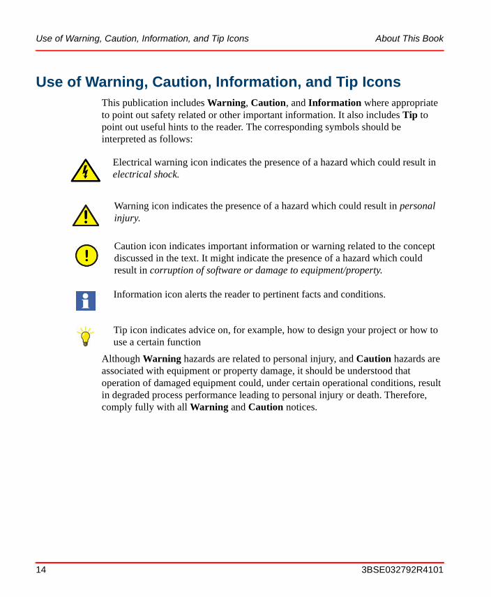
Use of Warning, Caution, Information, and Tip IconsThis publication includes Warning, Caution, and Information where appropriate to point out safety related or other important information. It also includes Tip to point out useful hints to the reader. The corresponding symbols should be interpreted as follows:
Although Warning hazards are related to personal injury, and Caution hazards are associated with equipment or property damage, it should be understood that operation of damaged equipment could, under certain operational conditions, result in degraded process performance leading to personal injury or death. Therefore, comply fully with all Warning and Caution notices.
Electrical warning icon indicates the presence of a hazard which could result in electrical shock.
Warning icon indicates the presence of a hazard which could result in personal injury.
Caution icon indicates important information or warning related to the concept discussed in the text. It might indicate the presence of a hazard which could result in corruption of software or damage to equipment/property.
Information icon alerts the reader to pertinent facts and conditions.
Tip icon indicates advice on, for example, how to design your project or how to use a certain function
14 3BSE032792R4101
About This Book Terminology
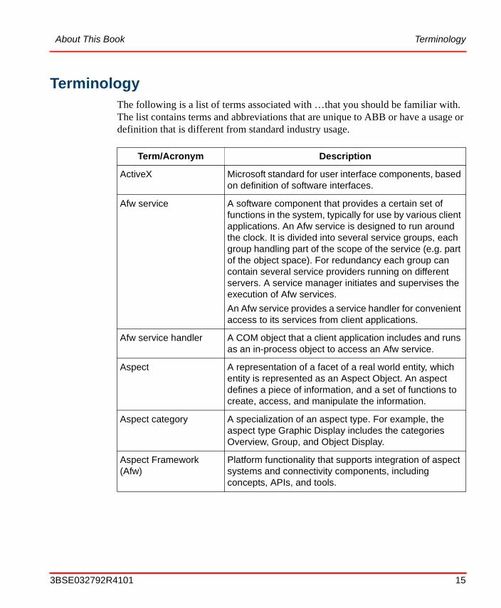
TerminologyThe following is a list of terms associated with …that you should be familiar with. The list contains terms and abbreviations that are unique to ABB or have a usage or definition that is different from standard industry usage.
Term/Acronym Description
ActiveX Microsoft standard for user interface components, based on definition of software interfaces.
Afw service A software component that provides a certain set of functions in the system, typically for use by various client applications. An Afw service is designed to run around the clock. It is divided into several service groups, each group handling part of the scope of the service (e.g. part of the object space). For redundancy each group can contain several service providers running on different servers. A service manager initiates and supervises the execution of Afw services.
An Afw service provides a service handler for convenient access to its services from client applications.
Afw service handler A COM object that a client application includes and runs as an in-process object to access an Afw service.
Aspect A representation of a facet of a real world entity, which entity is represented as an Aspect Object. An aspect defines a piece of information, and a set of functions to create, access, and manipulate the information.
Aspect category A specialization of an aspect type. For example, the aspect type Graphic Display includes the categories Overview, Group, and Object Display.
Aspect Framework (Afw)
Platform functionality that supports integration of aspect systems and connectivity components, including concepts, APIs, and tools.
3BSE032792R4101 15
Terminology About This Book
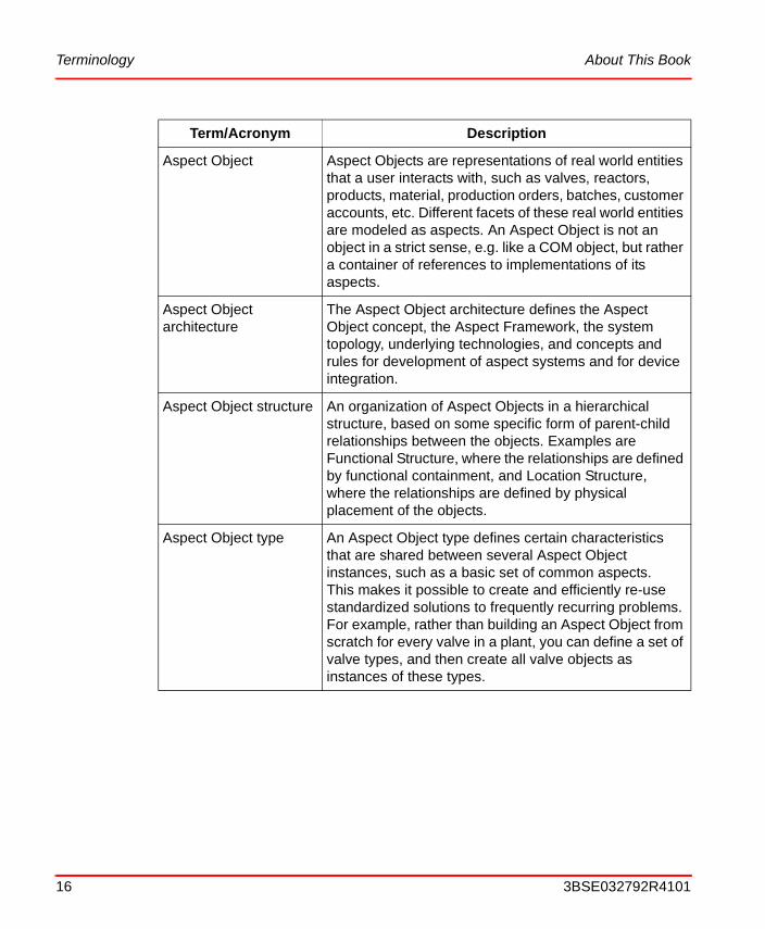
Aspect Object Aspect Objects are representations of real world entities that a user interacts with, such as valves, reactors, products, material, production orders, batches, customer accounts, etc. Different facets of these real world entities are modeled as aspects. An Aspect Object is not an object in a strict sense, e.g. like a COM object, but rather a container of references to implementations of its aspects.
Aspect Object architecture
The Aspect Object architecture defines the Aspect Object concept, the Aspect Framework, the system topology, underlying technologies, and concepts and rules for development of aspect systems and for device integration.
Aspect Object structure An organization of Aspect Objects in a hierarchical structure, based on some specific form of parent-child relationships between the objects. Examples are Functional Structure, where the relationships are defined by functional containment, and Location Structure, where the relationships are defined by physical placement of the objects.
Aspect Object type An Aspect Object type defines certain characteristics that are shared between several Aspect Object instances, such as a basic set of common aspects. This makes it possible to create and efficiently re-use standardized solutions to frequently recurring problems. For example, rather than building an Aspect Object from scratch for every valve in a plant, you can define a set of valve types, and then create all valve objects as instances of these types.
Term/Acronym Description
16 3BSE032792R4101
About This Book Terminology
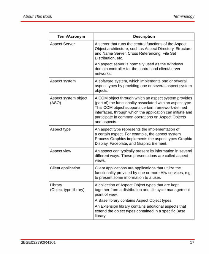
Aspect Server A server that runs the central functions of the Aspect Object architecture, such as Aspect Directory, Structure and Name Server, Cross Referencing, File Set Distribution, etc.
An aspect server is normally used as the Windows domain controller for the control and client/server networks.
Aspect system A software system, which implements one or several aspect types by providing one or several aspect system objects.
Aspect system object (ASO)
A COM object through which an aspect system provides (part of) the functionality associated with an aspect type. This COM object supports certain framework-defined interfaces, through which the application can initiate and participate in common operations on Aspect Objects and aspects.
Aspect type An aspect type represents the implementation of a certain aspect. For example, the aspect system Process Graphics implements the aspect types Graphic Display, Faceplate, and Graphic Element.
Aspect view An aspect can typically present its information in several different ways. These presentations are called aspect views.
Client application Client applications are applications that utilize the functionality provided by one or more Afw services, e.g. to present some information to a user.
Library (Object type library)
A collection of Aspect Object types that are kept together from a distribution and life cycle management point of view.
A Base library contains Aspect Object types.
An Extension library contains additional aspects that extend the object types contained in a specific Base library
Term/Acronym Description
3BSE032792R4101 17

Applicable Specifications About This Book
Applicable SpecificationsThis product meets the requirements specified in EMC Directive 89/336/EEC and in Low Voltage Directive 72/23/EEC.
Server A node that runs one or several Afw Services
Service A software component that provides a certain set of functions in the system, typically for use by various client applications. See also Afw service.
System extension A system extension consists of one or more system applications that are bundled as an extension to one or several existing system products. A system extension can only be installed if (one of) the corresponding system product(s) has been installed previously.
System version A system version defines the collection of specific versions of Industrial IT products, as well as operating system and similar components, which constitute a system offering at a given point in time.
Term/Acronym Description
18 3BSE032792R4101
About This Book Related Documentation
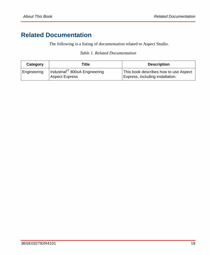
Related DocumentationThe following is a listing of documentation related to Aspect Studio.
Table 1. Related Documentation
Category Title Description
Engineering IndustrialIT 800xA EngineeringAspect Express
This book describes how to use Aspect Express, including installation.
3BSE032792R4101 19
Related Documentation About This Book
20 3BSE032792R4101

Section 1 Introduction
The Aspect StudioTM is designed to run on the Windows XP Professional and Windows 2003 Server platforms. It includes features to cover the complete aspect system software development process - from setting up the aspect development environment for Microsoft Visual Studio to generation of distributable software packages and service packs.
Note that this book is not intended to be the sole source of information for the Aspect Studio. It is therefore recommended that people involved in aspect software development, configuration management, and product management attend the applicable training courses offered by ABB Automation Technologies AB.
Product OverviewThe Aspect Studio is designed to support all the steps needed to create a distributable software product. This means that it helps you set up the development environment you need, to create Visual Source Safe databases, to create templates for Aspect Systems, to fetch baselines from Visual Source Safe, and much more. The Aspect Studio can be used both by software developers and product managers. It has tools that support both specific programming activities and generation of new software versions.
The Aspect Studio tools uses the API's of Microsoft Visual Sourcesafe and Microsoft Visual Studio to accomplish the tasks mentioned above.
Below is an overview description of all the Aspect Studio tools.
3BSE032792R4101 21
Product Scope Section 1 Introduction
Product Scope
The Aspect Studio software package contains mainly the following software tools:
• Environment SetupThe Environment Setup tool helps you set up the required development environment, based on the product you are going to develop, and the IndustrialIT components you want to include in the product.
• Aspect Objects AppWizardThe Aspect Objects AppWizard is used to create C++ templates for all of the most important functions of an aspect system, and thus significantly increase the productivity of C++ aspect system developers.
• The Build Manager contains a list of all activities you will need when you build a product. The list is complete and covers all steps form VSS baseline creation to product packaging and deployment. With the build manager you can:
– select an activity in the list make it execute instantly
– select a sequence of build activities and make them run as a scheduled job
• AutobuildThis tool has the capability to build (compile and link) the s/w of the current product, to build merge modules (MSM) for the Microsoft Installer and to sign components with strong names. All these activities are based on the same set of metadata (the build.abc files) and can be fired interactively or as a scheduled job (i.e. one build, one activation can cover hundreds of visual studio solutions and also other kind of components like VB6 projects, data copying components etc). The autobuild tool is available from the Visual Studio desktop and from the Aspect Studio/Build Manager tool.
• PostScript GeneratorThe PostScript Generator is used to generate postscript files from any plain text files with line number etc..
• Product PackagerYou use the Product Packager to generate software distribution packages. It can also be used to build service packs and extension packs. By installing a service pack, you can correct a software and have it work the same way as if you install a complete new version of the software. By installing an extension pack you can add new functionality to an installed product.
22 3BSE032792R4101
Section 1 Introduction What You Can Do with the Aspect Studio Toolbox
This can be additional end-user functionality e.g. a product option that was released after the product was shipped or it can be additional functions for product maintenance like the PDB files and source code for debugging reasons.
• Product ViewerLets you view details of software installed or MSI setup package, both ABB’s and other vendor’s software packages.
• Aspect ExpressAspect Express is an application development kit that provides functionality which simplifies the creation of Aspect Systems.
The Aspect Express package consists of two main tools:
– Aspect Express Builder A tool for configuration of Aspect Systems.
– Aspect Express Packager The installation and distribution tools for the created Aspect System(s).
What You Can Do with the Aspect Studio Toolbox
The Aspect Studio Menu
You can start up all of the Aspect Studio tools by first clicking on the Start button and then select the tool you are going to use. See Figure 1.
Aspect Express is described in the IndustrialIT 800xA, Engineering, Aspect Express instruction.
3BSE032792R4101 23

What You Can Do with the Aspect Studio Toolbox Section 1 Introduction
Below is an introduction to all of the tools included in the Aspect Studio.
The Environment Setup tool
The Environment Setup tool sets up the development environment you need to build your System Extension, generate a new software version. This means, for example, that the Environment Setup tool sets up all the paths and environment variables that MS Visual Studio requires.
After you have started the Environment Setup tool, you specify the name of the application (product) you are going to develop. This can be the name of a product that is already installed on your system (runtime and SDK), for example Process Portal with Process Portal SDK or 800xA for Advant Master with SDK etc., but you can also choose to start the development of a new application by specifying a name, for example Rollmill, and the tool will create and install a template for you, in this case Rollmill with Rollmill SDK.
Based on the product name you have entered, the Environment Setup tool will set up your development environment regarding the following:
• Directory paths for MS Visual StudioThe directory path settings for MS Visual Studio VC++ projects.
• A directory structureThe Environment Setup tool sets up a directory structure according to the ABB standard structure for IndustrialIT products.
Figure 1. Starting up the Aspect Studio Tools
24 3BSE032792R4101
Section 1 Introduction What You Can Do with the Aspect Studio Toolbox
• Assemblies with strong nameThe tool generates key files to sign assemblies with strong name. It turns verification off for key validation and puts keys in folder structure.
After you have run the Environment Setup tool, you are ready to start developing and building your application.
The Aspect Objects AppWizard
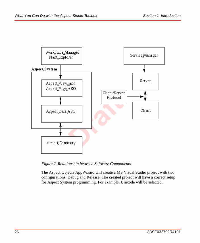
The Aspect Objects AppWizard significantly simplifies creation of Aspect System, System Extension, Service and Test Project applications.By using the Aspect Objects AppWizard, you can create skeletons forAspect Views, Aspect Pages, Aspect Data, Aspect Verbs, Servers, Protocols and Clients. Figure 2 illustrates the relationship between some of the components.
3BSE032792R4101 25
What You Can Do with the Aspect Studio Toolbox Section 1 Introduction
The Aspect Objects AppWizard will create a MS Visual Studio project with two configurations, Debug and Release. The created project will have a correct setupfor Aspect System programming. For example, Unicode will be selected.
Figure 2. Relationship between Software Components
26 3BSE032792R4101
Section 1 Introduction What You Can Do with the Aspect Studio Toolbox
Below is a short introduction to some of the concepts mentioned above:
Aspect Systems
Aspect Systems are the primary way to integrate functionality into the IndustrialIT system. After an Aspect System has been registered in the Aspect Directory, you can create an aspect and operate on an aspect that belongs to the Aspect System.
Much of the flexibility and modularity of the IndustrialIT system derives from the fact that both the Process Portal functionality and additional user functionality are implemented in the same way. Which means that all add-on user functionalities will be very well integrated into the complete system.
System Extensions
A System Extension, or a System Product Extension, consists of one or more applications that are bundled as an extension to one or several existing System Products. Example: 800xA for Advant Master is a system product extension to 800xA System.
The Aspect Studio tools provide support for creation and development of system extensions. Install the “System Product” with its SDK, install Aspect Studio, start up the Environment Setup tool, and enter the name of your System Extension and the disk location where you want it to be installed. Press the OK button, and after a few seconds your System Extension will be prepared. From start, its SDK contains only the source files necessary for installing the product.
Now you can start the development by using the Aspect Objects AppWizard. By using this tool, you can easily add the component that becomes the interface between your System Extension and the System Product. Then you can add one or several Aspect Systems, and you can easily re-build the installation kit by using the Aspect Studio Product Packager. When you install the System Extension on another machine, it will be installed with the interface component, your Aspect Systems and, depending on your choices, with or without the SDK, and with or without the source files.
By using Aspect Studio for creation and development of different System Extensions, they will get a uniform look and feel for developers, system administrators, operators etc., and the build and install definition files will, to a high extent, be automatically generated.
3BSE032792R4101 27

What You Can Do with the Aspect Studio Toolbox Section 1 Introduction
Services
Using the Aspect Objects AppWizard, you can create a template for a Simple Service or a Socket Service. A Simple Service is an executable without any connection to a client, whereas a Socket Service supports a server and a client that communicate with each other using a socket based protocol.
A Socket Service uses Winsocket for the communication between a client and the server. The wizard generates three projects, one Server project, one Client project, and a protocol project that defines the socket protocol used between the client and the server. The procedure you use to create a Socket Service is the same as the procedure for a Simple Service.
Test Project
A Test Project is a project to which you can add test components which fit into ABB’s framework for automated tests. Each part of the 800xA System is tested through such automated tests. When you have created your test project, you can add test components through “New ATL object”.
A test component is a COM object that holds a test suite, that is, a number of test cases. The wizard creates a complete example, containing one test case, to help the programmer to get started.
The Autobuild Tool
The Autobuild tool is available as an add-in to the Microsoft Visual Studio desktop and from the "Build related" dialog of the Aspect Studio Build Manager tool. Developers will use autobuild from Microsoft Visual Studio in their day-to-day work while product build managers will use autobuild from the Build Manager when they are composing batch oriented build jobs containing all activities from baseline creation to product packaging. The tool provides support for:
• Compile & Link Visual Studio projects.
• Create MSM's (Microsoft Installer merge modules).
Test Projects are to be used for API tests only, not for UI (User Interface) tests.
28 3BSE032792R4101
Section 1 Introduction What You Can Do with the Aspect Studio Toolbox
• Installation in to Global Assembly Cache (GAC) or assemblies, and interoperability for use of assemblies in COM. Handles re-signing of assemblies which are set to delay signed.
The Autobuild tool supports building of Visual Basic and Visual Studio .NET projects.
The Build Manager
The main functions of the Build Manager is version control and build management of families of MS Visual Studio components. The Build Manager handles baseline creation and component build in a batch oriented way. You can use the Build Manager user interface to set up the following:
• which VSS (Visual Source Safe) repositories to be involved
• what baseline to be created or used
• which build operations to be activated, and
• in which order the different baseline and build operations shall be activated.
The PostScript Generator
The PostScript Generator is used to generate one or several postscript file(s) from one or several selected file(s). The PostScript Generator can, for example, print C++ and VB files. The PostScript Generator can be configured to include line numbers in the postscript file. The result is then mainly used for code reviews.
The Product Packager
The Product Packager tool supports the following features:
Generate Distribution Packages
The Product packager lets you generate distributions interactively or in batch. The result will be the same, but generating in batch mode lets you generate a product package from a script. Scripts for packaging products can be automatically created by using the Aspect Studio/Build Manager. The Product Packager creates a structure that is complete in the sense that it is ready for installation on a target node by using the Microsoft Windows Installer (MSI).
3BSE032792R4101 29

What You Can Do with the Aspect Studio Toolbox Section 1 Introduction
Install a Distribution Package
A distribution package, available on an installation server or on a CD-ROM, will contain a setup program that handles the installation. After you have started the setup program, dialog boxes will guide you through the complete installation procedure.
Re-install, un-install, and modify a Product Package
Sometimes there can be a need to re-install, un-install, or change a product package. The functionality required for this is provided by the Windows Installer.
The Service Pack Builder
The Service Pack Builder, which is a part of the Product Packager, supports generation of service packs. By installing a service pack, you can correct a software and have it work the same way as if you install a complete new version of the software.
The Extension Pack Builder
The Extension Pack Builder, which is a part of the Product Packager, supports generation of extension packs. By installing an extension pack you can add new functionality to an installed product. This can be additional end-user functionality e.g. a product option that was released after the product was shipped or it can be additional functions for product maintenance like the PDB files and source code for debugging reasons.
The Product Viewer
With the Product Viewer you can inspect not only the ABB software you have installed, but also other vendor’s software, installed with Windows Installer.
30 3BSE032792R4101
Section 1 Introduction What’s New in This Release
Aspect Express
Aspect Express is an application development kit that provides functionality which simplifies the creation of Aspect Systems.
Aspect Express consists of two main tools:
• Aspect Express Builder A tool for configuration of Aspect Systems.
• Aspect Express Packager The installation and distribution tools for the created Aspect System(s).
What’s New in This Release
Please read the release notes for more information about what is new in this release.
Product Release History
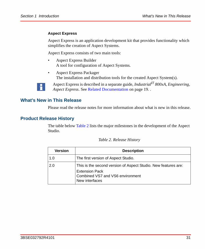
The table below Table 2 lists the major milestones in the development of the Aspect Studio.
Aspect Express is described in a separate guide, IndustrialIT 800xA, Engineering, Aspect Express. See Related Documentation on page 19. .
Table 2. Release History
Version Description
1.0 The first version of Aspect Studio.
2.0 This is the second version of Aspect Studio. New features are:
Extension PackCombined VS7 and VS6 environmentNew interfaces
3BSE032792R4101 31
Product Release History Section 1 Introduction
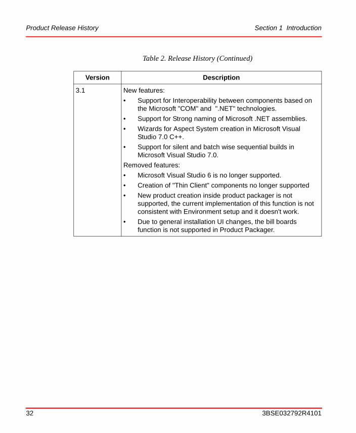
3.1 New features:
• Support for Interoperability between components based on the Microsoft "COM" and ".NET" technologies.
• Support for Strong naming of Microsoft .NET assemblies.
• Wizards for Aspect System creation in Microsoft Visual Studio 7.0 C++.
• Support for silent and batch wise sequential builds in Microsoft Visual Studio 7.0.
Removed features:
• Microsoft Visual Studio 6 is no longer supported.
• Creation of "Thin Client" components no longer supported
• New product creation inside product packager is not supported, the current implementation of this function is not consistent with Environment setup and it doesn't work.
• Due to general installation UI changes, the bill boards function is not supported in Product Packager.
Table 2. Release History (Continued)
Version Description
32 3BSE032792R4101
Section 1 Introduction Product Release History
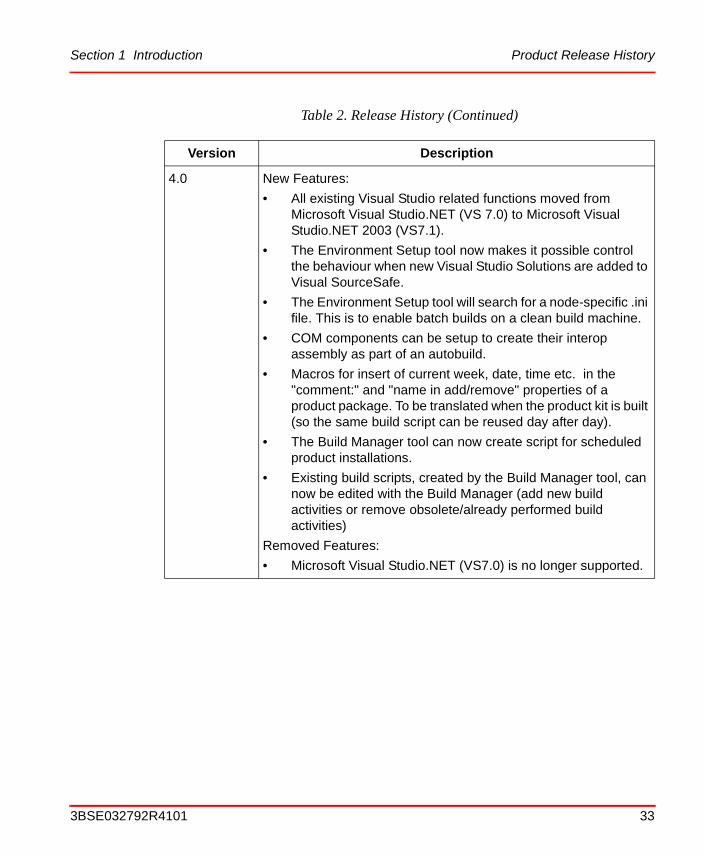
4.0 New Features:
• All existing Visual Studio related functions moved from Microsoft Visual Studio.NET (VS 7.0) to Microsoft Visual Studio.NET 2003 (VS7.1).
• The Environment Setup tool now makes it possible control the behaviour when new Visual Studio Solutions are added to Visual SourceSafe.
• The Environment Setup tool will search for a node-specific .ini file. This is to enable batch builds on a clean build machine.
• COM components can be setup to create their interop assembly as part of an autobuild.
• Macros for insert of current week, date, time etc. in the "comment:" and "name in add/remove" properties of a product package. To be translated when the product kit is built (so the same build script can be reused day after day).
• The Build Manager tool can now create script for scheduled product installations.
• Existing build scripts, created by the Build Manager tool, can now be edited with the Build Manager (add new build activities or remove obsolete/already performed build activities)
Removed Features:
• Microsoft Visual Studio.NET (VS7.0) is no longer supported.
Table 2. Release History (Continued)
Version Description
3BSE032792R4101 33
Prerequisites and Requirements Section 1 Introduction
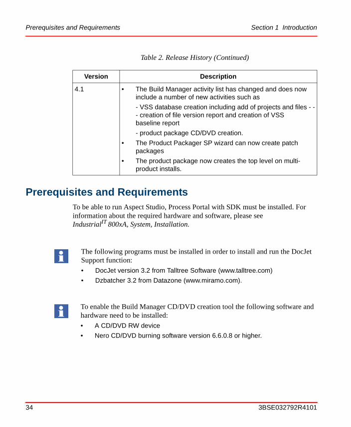
Prerequisites and Requirements
To be able to run Aspect Studio, Process Portal with SDK must be installed. For information about the required hardware and software, please see IndustrialIT 800xA, System, Installation.
4.1 • The Build Manager activity list has changed and does now include a number of new activities such as
- VSS database creation including add of projects and files - -- creation of file version report and creation of VSS baseline report
- product package CD/DVD creation.
• The Product Packager SP wizard can now create patch packages
• The product package now creates the top level on multi-product installs.
The following programs must be installed in order to install and run the DocJet Support function:
• DocJet version 3.2 from Talltree Software (www.talltree.com)
• Dzbatcher 3.2 from Datazone (www.miramo.com).
To enable the Build Manager CD/DVD creation tool the following software and hardware need to be installed:
• A CD/DVD RW device
• Nero CD/DVD burning software version 6.6.0.8 or higher.
Table 2. Release History (Continued)
Version Description
34 3BSE032792R4101
Section 2 Installation
To install the Aspect Studio software package on the target node, perform as follows:
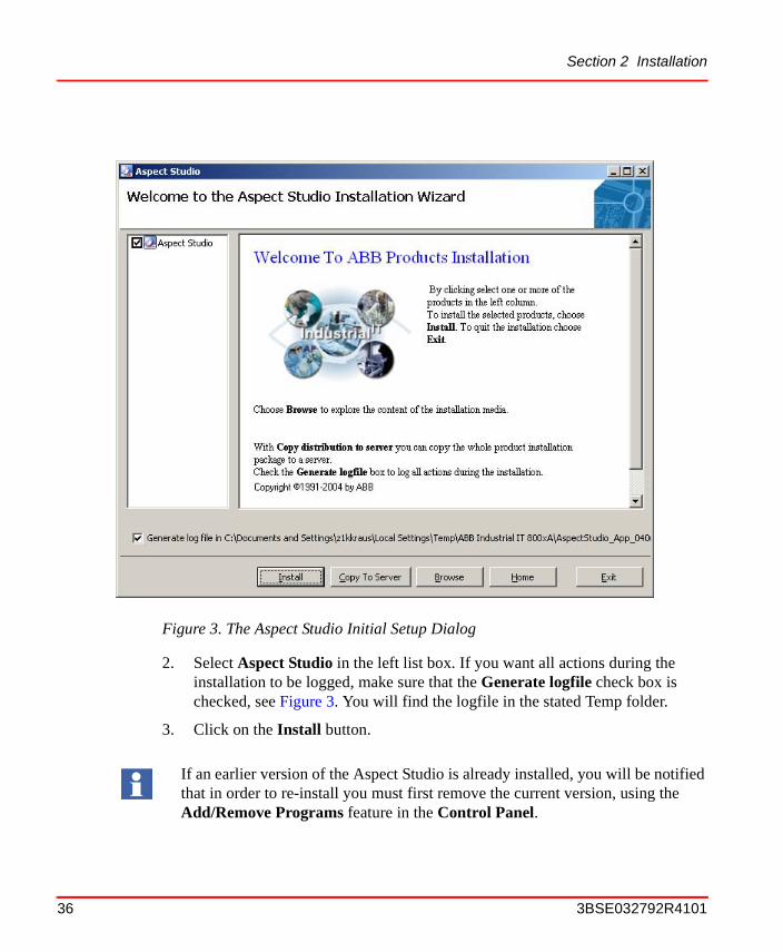
1. If you have the Aspect Studio software package on a CD-ROM, insert the CD into the CD-ROM drive. After a few seconds a setup dialog will appear, see Figure 3. If not, double click on the Setup.exe icon on the CD-ROM.
If the Aspect Studio is stored on a server, find the folder where it is stored, double click on the Setup.exe icon, and the setup dialog will appear.
3BSE032792R4101 35
Section 2 Installation
2. Select Aspect Studio in the left list box. If you want all actions during the installation to be logged, make sure that the Generate logfile check box is checked, see Figure 3. You will find the logfile in the stated Temp folder.
3. Click on the Install button.
Figure 3. The Aspect Studio Initial Setup Dialog
If an earlier version of the Aspect Studio is already installed, you will be notified that in order to re-install you must first remove the current version, using the Add/Remove Programs feature in the Control Panel.
36 3BSE032792R4101
Section 2 Installation
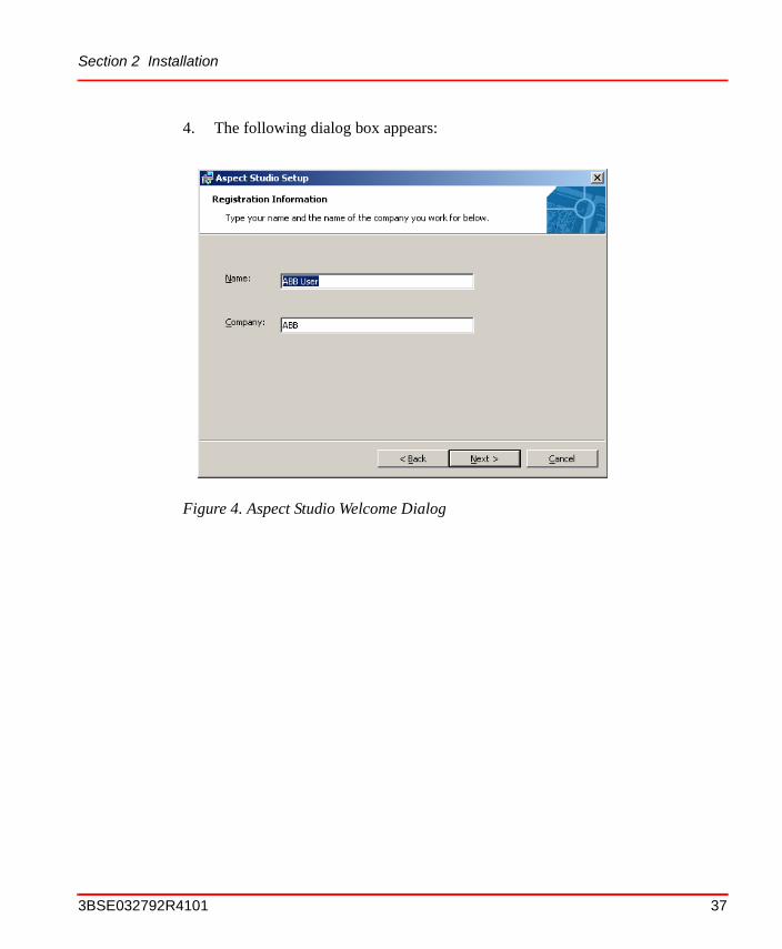
4. The following dialog box appears:
Figure 4. Aspect Studio Welcome Dialog
3BSE032792R4101 37

Section 2 Installation
5. Press Next, read and Accept the license terms, enter name and company, press Next one more time and then the following dialog-box appears:
Figure 5. Dialog Box for Selection of which Aspect Studio Features to Install
The features AppWizard for Visual Studio 7 and Autobuild for Visual Studio 7 will install successfully only if Microsoft Visual Studio.NET 2003 (VS 7.1) is installed on the target host. If you, later on, install Visual Studio.NET 2003 and you want to add these features, run Aspect Studio re-install.
The Feature DocJet Support requires that DocJet and DZbatcher are installed. If these programs are not installed and DocJet Support is chosen to be installed, the installation of Aspect Studio will fail and rollback. The DocJet support is by default not chosen to be installed.
To make use of the Aspect Express feature you must have Microsoft Visual Basic version 6.0 is installed on the target host. If missing and if you, later on, install Microsoft Visual Basic 6.0 and you want to add this feature, run Aspect Studio re-install. The Aspect Express feature is by default not installed.
38 3BSE032792R4101
Section 2 Installation
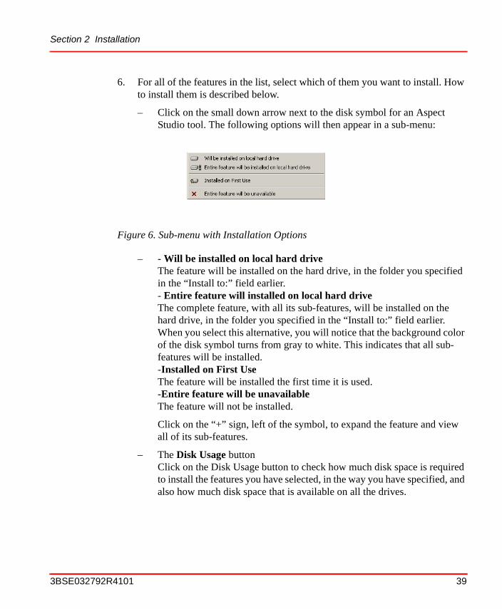
6. For all of the features in the list, select which of them you want to install. How to install them is described below.
– Click on the small down arrow next to the disk symbol for an Aspect Studio tool. The following options will then appear in a sub-menu:
– - Will be installed on local hard driveThe feature will be installed on the hard drive, in the folder you specified in the “Install to:” field earlier.- Entire feature will installed on local hard driveThe complete feature, with all its sub-features, will be installed on the hard drive, in the folder you specified in the “Install to:” field earlier. When you select this alternative, you will notice that the background color of the disk symbol turns from gray to white. This indicates that all sub-features will be installed.-Installed on First UseThe feature will be installed the first time it is used.-Entire feature will be unavailableThe feature will not be installed.
Click on the “+” sign, left of the symbol, to expand the feature and view all of its sub-features.
– The Disk Usage buttonClick on the Disk Usage button to check how much disk space is required to install the features you have selected, in the way you have specified, and also how much disk space that is available on all the drives.
Figure 6. Sub-menu with Installation Options
3BSE032792R4101 39
Reinstall, uninstall and change Section 2 Installation
– The Reset buttonResets your installation set-up (which features and how) to the default values.
– The <Back buttonReturns to the previous dialog box.
– The >Next buttonOpens the next dialog box. That is, the installation proceeds.
Press the Install button.
7. When the installation is successfully completed, a message box telling that “Aspect Studio installed successfully” will pop up. You can then decide whether you want to take a look at the read-me file or not.
Now you are ready to start using the Aspect Studio tools.
Reinstall, uninstall and change
To reinstall, uninstall or change the Aspect Studio installation you can:
a. start up the installation again by clicking on the setup.exe as described above
b. go to the Add or Remove Programs menu, locate the line with Aspect Studio and press the Change button.
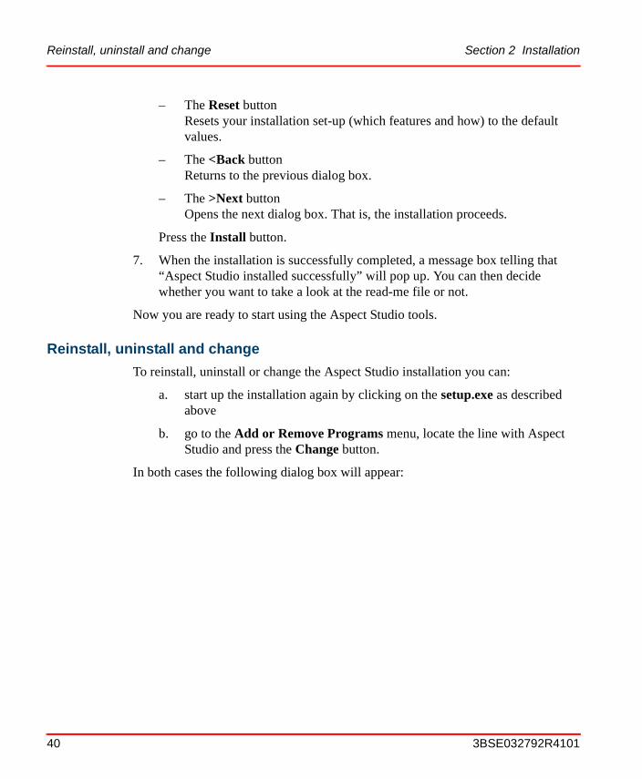
In both cases the following dialog box will appear:
40 3BSE032792R4101
Section 2 Installation Start-up and shut-down Procedures
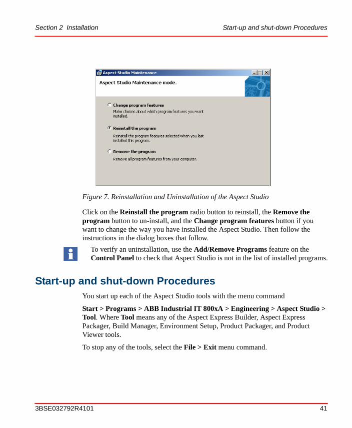
Click on the Reinstall the program radio button to reinstall, the Remove the program button to un-install, and the Change program features button if you want to change the way you have installed the Aspect Studio. Then follow the instructions in the dialog boxes that follow.
Start-up and shut-down ProceduresYou start up each of the Aspect Studio tools with the menu command
Start > Programs > ABB Industrial IT 800xA > Engineering > Aspect Studio > Tool. Where Tool means any of the Aspect Express Builder, Aspect Express Packager, Build Manager, Environment Setup, Product Packager, and Product Viewer tools.
To stop any of the tools, select the File > Exit menu command.
Figure 7. Reinstallation and Uninstallation of the Aspect Studio
To verify an uninstallation, use the Add/Remove Programs feature on the Control Panel to check that Aspect Studio is not in the list of installed programs.
3BSE032792R4101 41
Verification of the Installation Section 2 Installation
Verification of the InstallationTo verify that all of the Aspect Studio tools have been installed, select the menu command:
Start > Programs > ABB Industrial IT 800xA > Engineering > Aspect Studio
You should then see, at maximum, the following options: Aspect Express Builder, Aspect Express Packager, Build Manager, Environment Setup, Postscript Generator, Product Packager, and Product Viewer. Note however, that one or more of these tools can be missing if you choose not to install them, or if you have removed some of them afterwards.
Try to start each of the tools in the menu to verify that the initial dialog box appears properly.
42 3BSE032792R4101
Section 3 Configuration
After installation you can configure Aspect Studio with the Aspect Studio Environment Setup tool.
This is done different depending on the situation as illustrated by the following examples:
Example 1
On your computer you have another Aspect Studio compliant product installed with its SDK (e.g. Process Portal A with Process Portal A SDK).
Now, when you start the Environment Setup tool, the "Process Portal A" product will appear in the list of products. You can then select "Process Portal A" from the list.
By executing the Environment Setup tool you will now setup your computer (Microsoft Visual Studio Cpp directory settings, environment variables and public/private encryption keys etc.) for development of the selected product.
Example 2
You want to configure your computer for developing a new product. You will start the Environment Setup tool and select to create a new product. You can choose to create a new "basic" product or you can, if another Aspect Studio compliant product is installed with its SDK, choose to create a new "based on" product.
By executing Environment Setup tool you will create directory structures, environment setup files etc. for the new product on your computer. By selecting the new product running the Environment Setup tool once more (as illustrated in example 1) you will now setup your computer (Microsoft Visual Studio Cpp directory settings, environment variables and public/private encryption keys etc.) for development of the new product.
3BSE032792R4101 43
Section 3 Configuration
44 3BSE032792R4101
Section 4 Operation
Operating OverviewFor an introduction to the Aspect Studio tools, please see Product Scope on page 22.
To get a quick introduction to using the Aspect Studio tools, for different purposes, you are recommended to read Work Flow Examples on page 47.
The Product StructureThe basic elements of the source code directory tree of an Aspect Studio compliant product are: Functional Subsystems, System Modules and Components. Each level contains a definition file, called a build.abc file, that tells which System Modules or Components (depending on the level) that are stored on the level below the level at hand. Example: A build.abc file for a Functional Subsystem specifies which System Modules that are part of the Functional Subsystem. The build.abc file also contains installation and administrative information. For example, a Component build.abc file contains information about files, short-cuts, system variables and registry entries included. A Microsoft Visual Studio solution (.sln) is typically implemented here as a Component with its different projects (.vcproj, .csproj) as subcomponents.
Note that the functionality of all of the tools in Aspect Studio are based on this structure. The figure below illustrates the relationships between Functional Subsystems, System Modules, Components, and Products. For a detailed description of the build.abc files and other structure aspects, see Appendix A, Build ABC File Configuration.
3BSE032792R4101 45

The Product Structure Section 4 Operation
Figure 8. The Relations between Functional Subsystems (FS x), System Modules (SM x:y), Components (Comp.x:y:z) and Products (Product xxx)
46 3BSE032792R4101
Section 4 Operation Getting Started
Getting Started
Prerequisites
The prerequisites for both of the two work flow examples below is that your PC meets the requirements regarding hardware and installed software as stated in Prerequisites and Requirements on page 34.
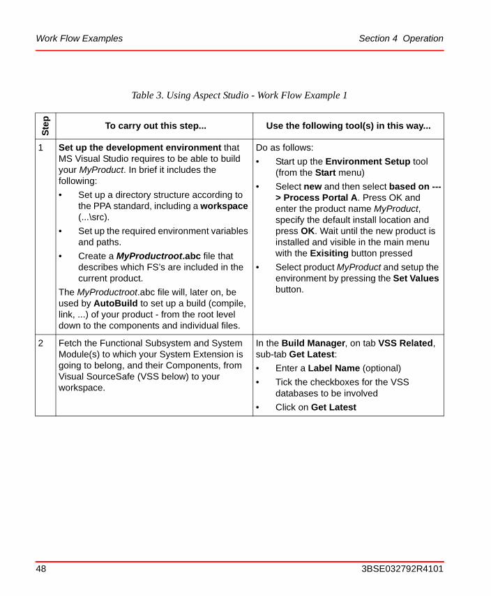
Work Flow ExamplesBelow are two work flow examples that will help you understand what Aspect Studio can do for you and which tools are involved to carry out the different steps. The work flows are described by means of tables with three columns. In the leftmost column is the step number, in the second is a description of what will be achieved by the step, and in the rightmost column you find a brief description of which tools to use and how to use them.
The work flow examples are directed towards two kinds of users: The first towards component developers, and the second towards product or project integrators. In the first work flow example, we will create and add a System Extension component to the product MyProduct. The second work flow example shows how to set up and create a build. All the required main steps are included, but not all details concerning how to carry out the steps are described. For a detailed description of each of the Aspect Studio tools, see respective subsection further down in this section.
Adding a New System Extension Component
This example is directed towards software developers. It shows the required steps to take to create a development environment, add a System Extension component, prepare the required build description (build.abc) files etc., and finally run a test build of the MSM modules.
We assume that the Build Manager operations are run interactively, that is, not as scheduled jobs.
3BSE032792R4101 47
Work Flow Examples Section 4 Operation
Table 3. Using Aspect Studio - Work Flow Example 1
Ste
p
To carry out this step... Use the following tool(s) in this way...
1 Set up the development environment that MS Visual Studio requires to be able to build your MyProduct. In brief it includes the following:
• Set up a directory structure according to the PPA standard, including a workspace (...\src).
• Set up the required environment variables and paths.
• Create a MyProductroot.abc file that describes which FS’s are included in the current product.
The MyProductroot.abc file will, later on, be used by AutoBuild to set up a build (compile, link, ...) of your product - from the root level down to the components and individual files.
Do as follows:
• Start up the Environment Setup tool (from the Start menu)
• Select new and then select based on ---> Process Portal A. Press OK and enter the product name MyProduct, specify the default install location and press OK. Wait until the new product is installed and visible in the main menu with the Exisiting button pressed
• Select product MyProduct and setup the environment by pressing the Set Values button.
2 Fetch the Functional Subsystem and System Module(s) to which your System Extension is going to belong, and their Components, from Visual SourceSafe (VSS below) to your workspace.
In the Build Manager, on tab VSS Related, sub-tab Get Latest:
• Enter a Label Name (optional)
• Tick the checkboxes for the VSS databases to be involved
• Click on Get Latest
48 3BSE032792R4101
Section 4 Operation Work Flow Examples
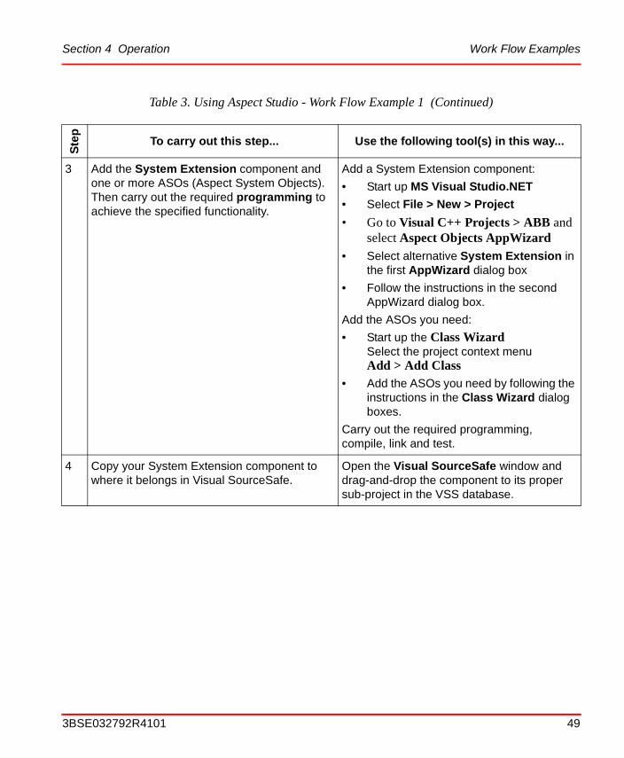
3 Add the System Extension component and one or more ASOs (Aspect System Objects). Then carry out the required programming to achieve the specified functionality.
Add a System Extension component:
• Start up MS Visual Studio.NET
• Select File > New > Project
• Go to Visual C++ Projects > ABB and select Aspect Objects AppWizard
• Select alternative System Extension in the first AppWizard dialog box
• Follow the instructions in the second AppWizard dialog box.
Add the ASOs you need:
• Start up the Class WizardSelect the project context menuAdd > Add Class
• Add the ASOs you need by following the instructions in the Class Wizard dialog boxes.
Carry out the required programming, compile, link and test.
4 Copy your System Extension component to where it belongs in Visual SourceSafe.
Open the Visual SourceSafe window and drag-and-drop the component to its proper sub-project in the VSS database.
Table 3. Using Aspect Studio - Work Flow Example 1 (Continued)
Ste
p
To carry out this step... Use the following tool(s) in this way...
3BSE032792R4101 49
Work Flow Examples Section 4 Operation
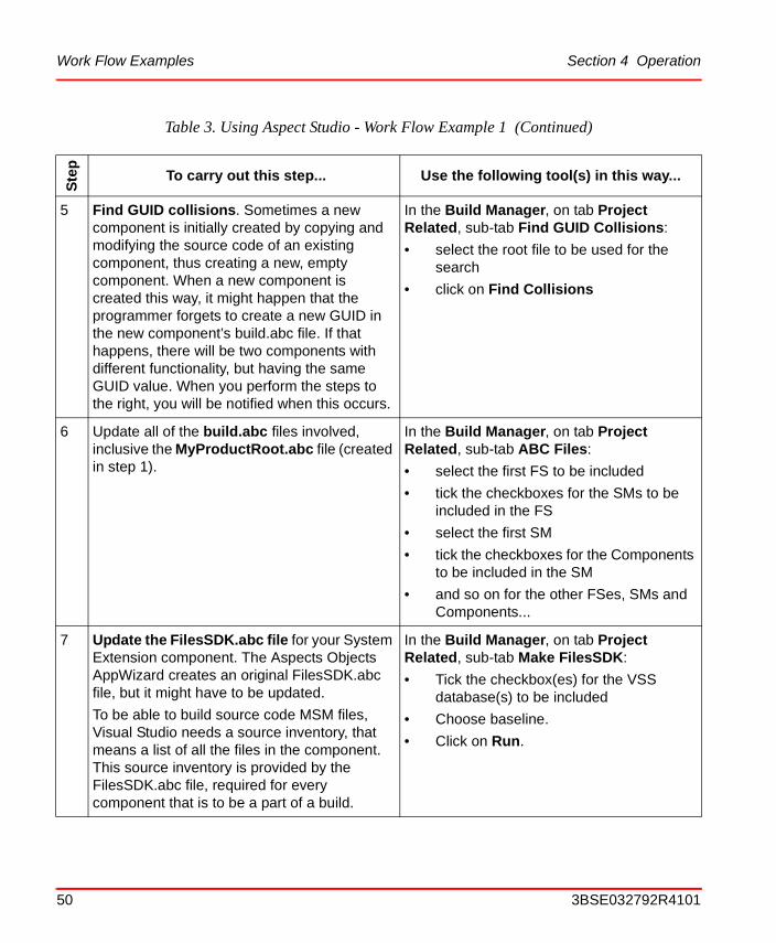
5 Find GUID collisions. Sometimes a new component is initially created by copying and modifying the source code of an existing component, thus creating a new, empty component. When a new component is created this way, it might happen that the programmer forgets to create a new GUID in the new component’s build.abc file. If that happens, there will be two components with different functionality, but having the same GUID value. When you perform the steps to the right, you will be notified when this occurs.
In the Build Manager, on tab Project Related, sub-tab Find GUID Collisions:
• select the root file to be used for the search
• click on Find Collisions
6 Update all of the build.abc files involved, inclusive the MyProductRoot.abc file (created in step 1).
In the Build Manager, on tab Project Related, sub-tab ABC Files:
• select the first FS to be included
• tick the checkboxes for the SMs to be included in the FS
• select the first SM
• tick the checkboxes for the Components to be included in the SM
• and so on for the other FSes, SMs and Components...
7 Update the FilesSDK.abc file for your System Extension component. The Aspects Objects AppWizard creates an original FilesSDK.abc file, but it might have to be updated.
To be able to build source code MSM files, Visual Studio needs a source inventory, that means a list of all the files in the component. This source inventory is provided by the FilesSDK.abc file, required for every component that is to be a part of a build.
In the Build Manager, on tab Project Related, sub-tab Make FilesSDK:
• Tick the checkbox(es) for the VSS database(s) to be included
• Choose baseline.
• Click on Run.
Table 3. Using Aspect Studio - Work Flow Example 1 (Continued)
Ste
p
To carry out this step... Use the following tool(s) in this way...
50 3BSE032792R4101
Section 4 Operation Work Flow Examples
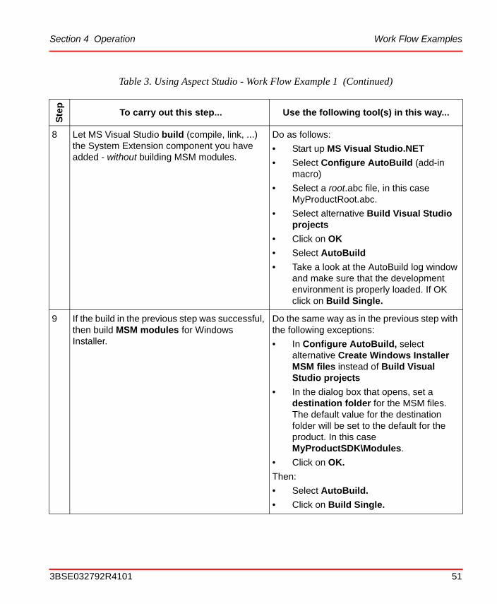
8 Let MS Visual Studio build (compile, link, ...) the System Extension component you have added - without building MSM modules.
Do as follows:
• Start up MS Visual Studio.NET
• Select Configure AutoBuild (add-in macro)
• Select a root.abc file, in this case MyProductRoot.abc.
• Select alternative Build Visual Studio projects
• Click on OK
• Select AutoBuild
• Take a look at the AutoBuild log window and make sure that the development environment is properly loaded. If OK click on Build Single.
9 If the build in the previous step was successful, then build MSM modules for Windows Installer.
Do the same way as in the previous step with the following exceptions:
• In Configure AutoBuild, select alternative Create Windows Installer MSM files instead of Build Visual Studio projects
• In the dialog box that opens, set a destination folder for the MSM files. The default value for the destination folder will be set to the default for the product. In this case MyProductSDK\Modules.
• Click on OK.
Then:
• Select AutoBuild.
• Click on Build Single.
Table 3. Using Aspect Studio - Work Flow Example 1 (Continued)
Ste
p
To carry out this step... Use the following tool(s) in this way...
3BSE032792R4101 51
Build of a Product Version Section 4 Operation
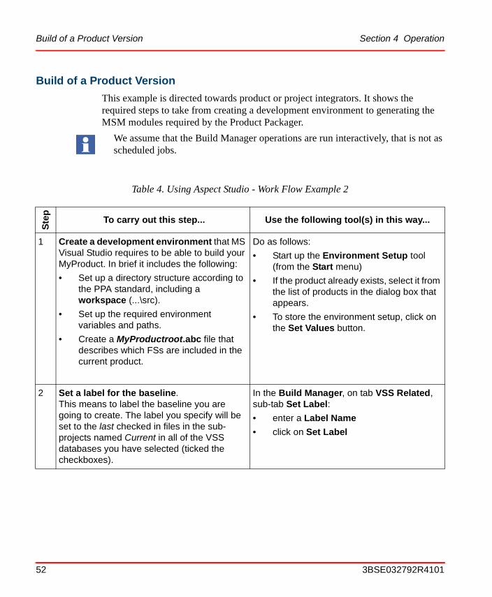
Build of a Product Version
This example is directed towards product or project integrators. It shows the required steps to take from creating a development environment to generating the MSM modules required by the Product Packager.
We assume that the Build Manager operations are run interactively, that is not as scheduled jobs.
Table 4. Using Aspect Studio - Work Flow Example 2
Ste
p
To carry out this step... Use the following tool(s) in this way...
1 Create a development environment that MS Visual Studio requires to be able to build your MyProduct. In brief it includes the following:
• Set up a directory structure according to the PPA standard, including a workspace (...\src).
• Set up the required environment variables and paths.
• Create a MyProductroot.abc file that describes which FSs are included in the current product.
Do as follows:
• Start up the Environment Setup tool (from the Start menu)
• If the product already exists, select it from the list of products in the dialog box that appears.
• To store the environment setup, click on the Set Values button.
2 Set a label for the baseline. This means to label the baseline you are going to create. The label you specify will be set to the last checked in files in the sub-projects named Current in all of the VSS databases you have selected (ticked the checkboxes).
In the Build Manager, on tab VSS Related, sub-tab Set Label:
• enter a Label Name
• click on Set Label
52 3BSE032792R4101
Section 4 Operation Build of a Product Version
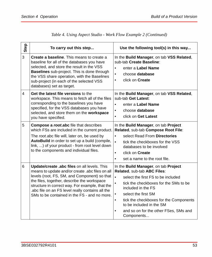
3 Create a baseline. This means to create a baseline for all of the databases you have selected, and store the result in the VSS Baselines sub-project. This is done through the VSS share operation, with the Baselines sub-project (in each of the selected VSS databases) set as target.
In the Build Manager, on tab VSS Related, sub-tab Create Baseline:
• enter a Label Name
• choose database
• click on Create
4 Get the latest file versions to the workspace. This means to fetch all of the files corresponding to the baselines you have specified, for the VSS databases you have selected, and store them on the workspace you have specified.
In the Build Manager, on tab VSS Related, sub-tab Get Latest:
• enter a Label Name
• choose database
• click on Get Latest
5 Compose a root.abc file that describes which FSs are included in the current product.
The root.abc file will, later on, be used by AutoBuild in order to set up a build (compile, link, ...) of your product - from root level down to the components and individual files.
In the Build Manager, on tab Project Related, sub-tab Compose Root File:
• select Read From Directories
• tick the checkboxes for the VSS databases to be involved
• click on Create
• set a name to the root file.
6 Update/create .abc files on all levels. This means to update and/or create .abc files on all levels (root, FS, SM, and Component) so that the files, together, describe the workspace structure in correct way. For example, that the .abc file on an FS level really contains all the SMs to be contained in the FS - and no more.
In the Build Manager, on tab Project Related, sub-tab ABC Files:
• select the first FS to be included
• tick the checkboxes for the SMs to be included in the FS
• select the first SM
• tick the checkboxes for the Components to be included in the SM
• and so on for the other FSes, SMs and Components...
Table 4. Using Aspect Studio - Work Flow Example 2 (Continued)
Ste
p
To carry out this step... Use the following tool(s) in this way...
3BSE032792R4101 53
Build of a Product Version Section 4 Operation
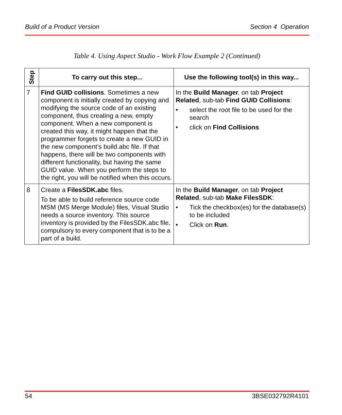
7 Find GUID collisions. Sometimes a new component is initially created by copying and modifying the source code of an existing component, thus creating a new, empty component. When a new component is created this way, it might happen that the programmer forgets to create a new GUID in the new component’s build.abc file. If that happens, there will be two components with different functionality, but having the same GUID value. When you perform the steps to the right, you will be notified when this occurs.
In the Build Manager, on tab Project Related, sub-tab Find GUID Collisions:
• select the root file to be used for the search
• click on Find Collisions
8 Create a FilesSDK.abc files.
To be able to build reference source code MSM (MS Merge Module) files, Visual Studio needs a source inventory. This source inventory is provided by the FilesSDK.abc file, compulsory to every component that is to be a part of a build.
In the Build Manager, on tab Project Related, sub-tab Make FilesSDK:
• Tick the checkbox(es) for the database(s) to be included
• Click on Run.
Table 4. Using Aspect Studio - Work Flow Example 2 (Continued)
Ste
p
To carry out this step... Use the following tool(s) in this way...
54 3BSE032792R4101
Section 4 Operation Build of a Product Version
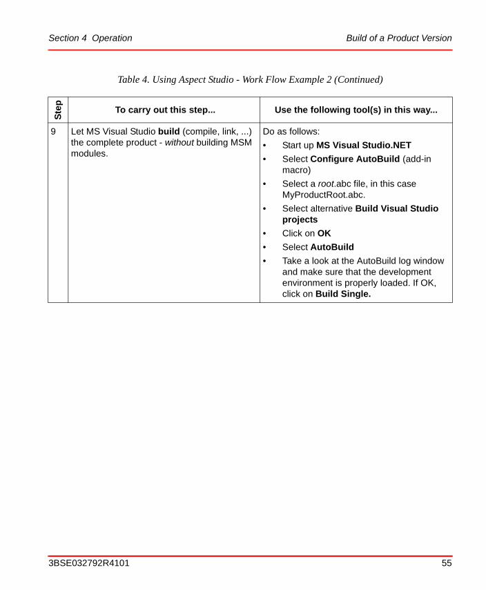
9 Let MS Visual Studio build (compile, link, ...) the complete product - without building MSM modules.
Do as follows:
• Start up MS Visual Studio.NET
• Select Configure AutoBuild (add-in macro)
• Select a root.abc file, in this case MyProductRoot.abc.
• Select alternative Build Visual Studio projects
• Click on OK
• Select AutoBuild
• Take a look at the AutoBuild log window and make sure that the development environment is properly loaded. If OK, click on Build Single.
Table 4. Using Aspect Studio - Work Flow Example 2 (Continued)
Ste
p
To carry out this step... Use the following tool(s) in this way...
3BSE032792R4101 55

Build of a Product Version Section 4 Operation
10 If the build in the previous step was successful, then build MSM modules for Windows Installer.
Do the same way as in the previous step with the following exceptions:
• In Configure AutoBuild, select alternative Create Windows Installer MSM files instead of Build Visual Studio projects
• In the dialog box that opens, set a destination folder for the MSM files
• Click on OK.
Then:
• Select “root” in the build tree view
• Select AutoBuild
• Click on Build Single.
11 Create an installable image. Do as follows:
• Start up the Product Packager
• Open the MyProduct_master.abp file (in ..\Definition Files)
• Select File > Project Settings
• ...see Section 10, The Product Packager for further instructions.
Table 4. Using Aspect Studio - Work Flow Example 2 (Continued)
Ste
p
To carry out this step... Use the following tool(s) in this way...
56 3BSE032792R4101
Section 5 The Environment Setup Tool
The Environment Setup tool is part of the Aspect Studio. Running the Environment Setup tool is the first step in the process of developing an application - no matter if it is the 800xA System basic software you are going to work with or some customer specific application.
What you can do with the Environment Setup toolThe Environment Setup tool sets up the development environment on the node where you perform the setup.
After you have started the Environment Setup tool, the first step is to choose an appropriate product template, in case you are going to create a new product, or select the name of a product, if you are going to work with an existing product. Examples for the latter case could be Process Portal A, or Advant Master with SDK etc. An example of a new product could be “Rollmill”. If it’s a new product, the Environment Setup tool will set up a product “Rollmill” with its software development environment “RollmillSDK”.
Based on the product name you have specified, the Environment Setup tool will set up your development environment regarding the following:
• Directory pathsThe directory path settings for MS Visual Studio VC++ projects. The list of directory paths will also include paths to required 3:rd party products. Which paths to 3:rd party products that are set up, is controlled by the product template you have selected.
• Environment VariablesThe Environment Variables required by MS Visual Studio to access and handle the entities of your product.
3BSE032792R4101 57
Getting Started Section 5 The Environment Setup Tool
• A directory structureThe Environment Setup tool sets up a directory structure according to the ABB standard structure for IndustrialIT products.
• Install the productA product containing the initial data and structures, with the name you have set, will be installed.
• Registry itemsSome values related to the product you specified will be inserted into the Windows Registry.
• Encryption keysA private-public keypair will be created for the product. To be used for strong name signing of components (the keys may later on be replaced by the official keys that are used by your company for all it's products).
After you have run the Environment Setup tool, your system is ready for development of the product you selected.
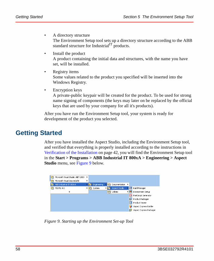
Getting StartedAfter you have installed the Aspect Studio, including the Environment Setup tool, and verified that everything is properly installed according to the instructions in Verification of the Installation on page 42, you will find the Environment Setup tool in the Start > Programs > ABB Industrial IT 800xA > Engineering > Aspect Studio menu, see Figure 9 below.
Figure 9. Starting up the Environment Set-up Tool
58 3BSE032792R4101
Section 5 The Environment Setup Tool Tutorial
Select the Environment Setup item in the menu, and the initial dialog box will appear, and you can start specifying the development framework for the application you are about to develop.
TutorialIn this section you will find a step-by-step example that describes how to set up the development environment for a product called MyProduct using the Environment Setup tool. The prerequisite for this example, is that all of the non-optional software packets according to Prerequisites and Requirements on page 34, have been properly installed.
Perform the following steps to create the development environment:
1. Start up the Environment Setup tool, see Figure 9.
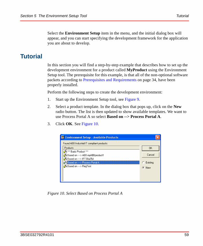
2. Select a product template. In the dialog box that pops up, click on the New radio button. The list is then updated to show available templates. We want to use Process Portal A so select Based on --> Process Portal A.
3. Click OK. See Figure 10.
Figure 10. Select Based on Process Portal A
3BSE032792R4101 59
Tutorial Section 5 The Environment Setup Tool
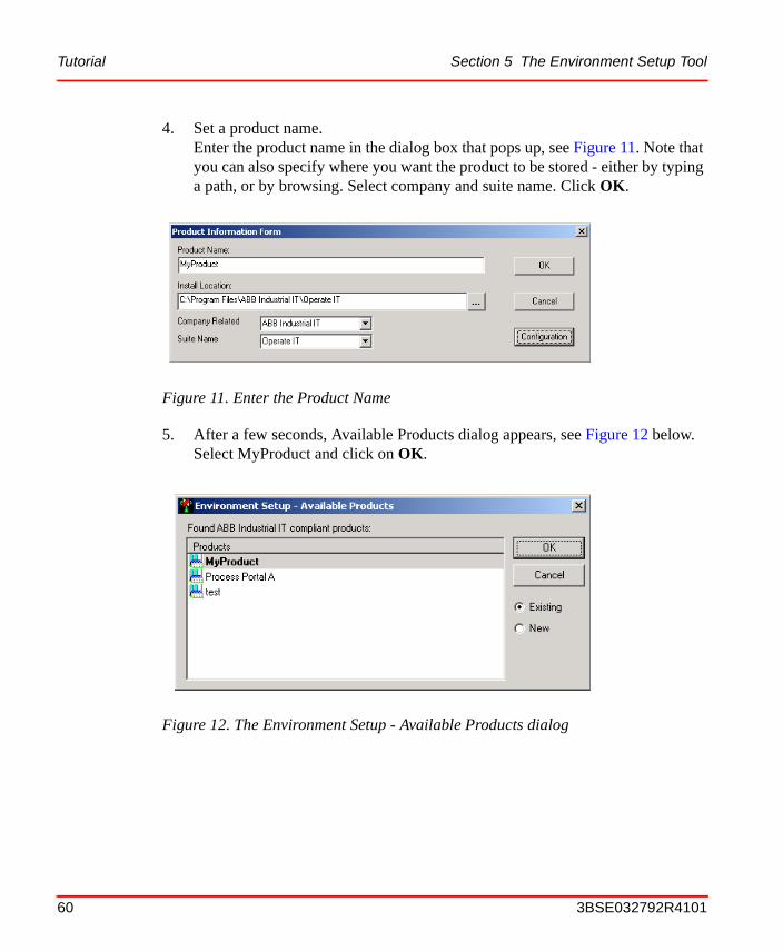
4. Set a product name.Enter the product name in the dialog box that pops up, see Figure 11. Note that you can also specify where you want the product to be stored - either by typing a path, or by browsing. Select company and suite name. Click OK.
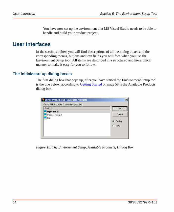
5. After a few seconds, Available Products dialog appears, see Figure 12 below. Select MyProduct and click on OK.
Figure 11. Enter the Product Name
Figure 12. The Environment Setup - Available Products dialog
60 3BSE032792R4101
Section 5 The Environment Setup Tool Tutorial
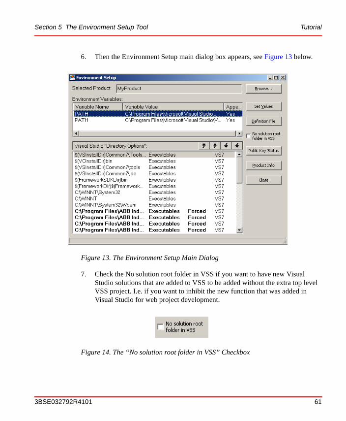
6. Then the Environment Setup main dialog box appears, see Figure 13 below.
7. Check the No solution root folder in VSS if you want to have new Visual Studio solutions that are added to VSS to be added without the extra top level VSS project. I.e. if you want to inhibit the new function that was added in Visual Studio for web project development.
Figure 13. The Environment Setup Main Dialog
Figure 14. The “No solution root folder in VSS” Checkbox
3BSE032792R4101 61
Tutorial Section 5 The Environment Setup Tool
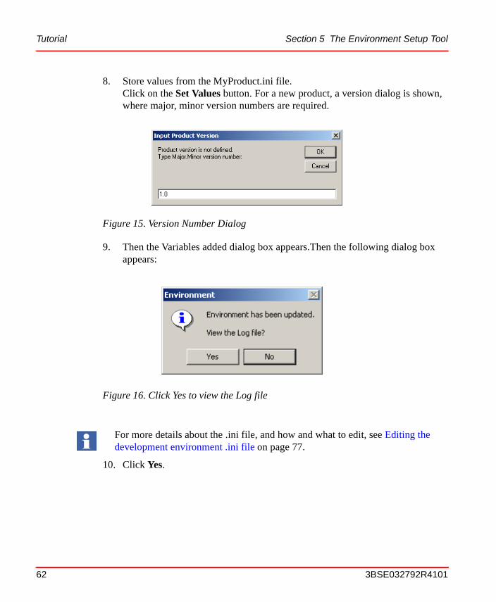
8. Store values from the MyProduct.ini file.Click on the Set Values button. For a new product, a version dialog is shown, where major, minor version numbers are required.
9. Then the Variables added dialog box appears.Then the following dialog box appears:
10. Click Yes.
Figure 15. Version Number Dialog
Figure 16. Click Yes to view the Log file
For more details about the .ini file, and how and what to edit, see Editing the development environment .ini file on page 77.
62 3BSE032792R4101
Section 5 The Environment Setup Tool Tutorial
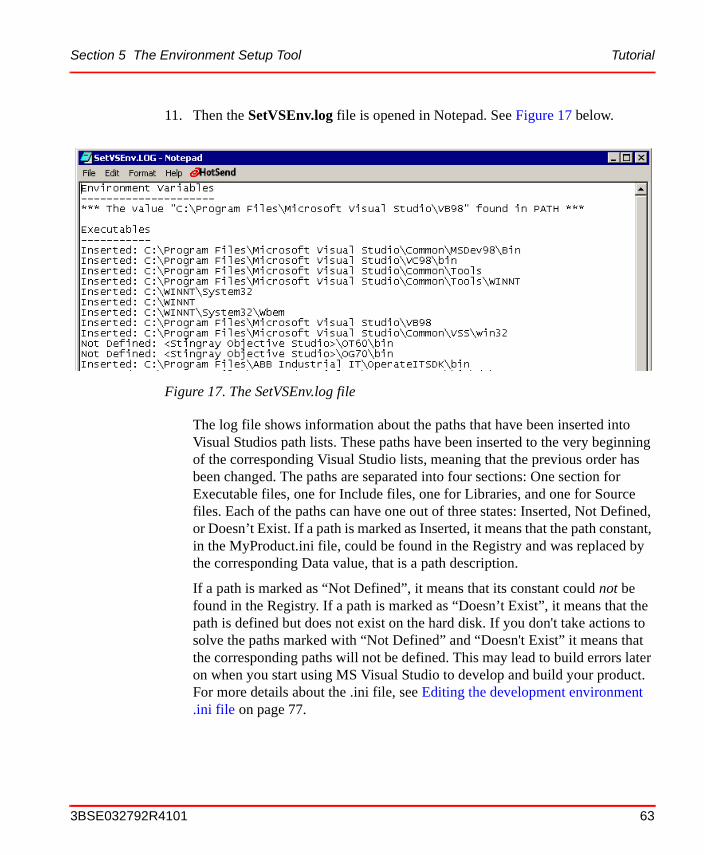
11. Then the SetVSEnv.log file is opened in Notepad. See Figure 17 below.
The log file shows information about the paths that have been inserted into Visual Studios path lists. These paths have been inserted to the very beginning of the corresponding Visual Studio lists, meaning that the previous order has been changed. The paths are separated into four sections: One section for Executable files, one for Include files, one for Libraries, and one for Source files. Each of the paths can have one out of three states: Inserted, Not Defined, or Doesn’t Exist. If a path is marked as Inserted, it means that the path constant, in the MyProduct.ini file, could be found in the Registry and was replaced by the corresponding Data value, that is a path description.
If a path is marked as “Not Defined”, it means that its constant could not be found in the Registry. If a path is marked as “Doesn’t Exist”, it means that the path is defined but does not exist on the hard disk. If you don't take actions to solve the paths marked with “Not Defined” and “Doesn't Exist” it means that the corresponding paths will not be defined. This may lead to build errors later on when you start using MS Visual Studio to develop and build your product. For more details about the .ini file, see Editing the development environment .ini file on page 77.
Figure 17. The SetVSEnv.log file
3BSE032792R4101 63
User Interfaces Section 5 The Environment Setup Tool
You have now set up the environment that MS Visual Studio needs to be able to handle and build your product project.
User InterfacesIn the sections below, you will find descriptions of all the dialog boxes and the corresponding menus, buttons and text fields you will face when you use the Environment Setup tool. All items are described in a structured and hierarchical manner to make it easy for you to follow.
The initial/start up dialog boxes
The first dialog box that pops up, after you have started the Environment Setup tool is the one below, according to Getting Started on page 58 is the Available Products dialog box.
Figure 18. The Environment Setup, Available Products, Dialog Box
64 3BSE032792R4101

Section 5 The Environment Setup Tool The initial/start up dialog boxes
Table 5. Available Products Dialog Box Items
Item Description
Products The currently available ABB IndustrialIT compliant products, that is, the products that are already set up through the Environment Setup tool. If you want to view and/or modify any of these products, select it (MyProduct in the figure) and click on OK.
Existing Click on that button to see all of the available products in the Products list (as shown in the figure).
New Click on this button to see all of the available templates in the Templates list, see Figure 19 below. Use this alternative when you want to create a new product.
Figure 19. The Environment Setup, Available Templates, Dialog Box
3BSE032792R4101 65
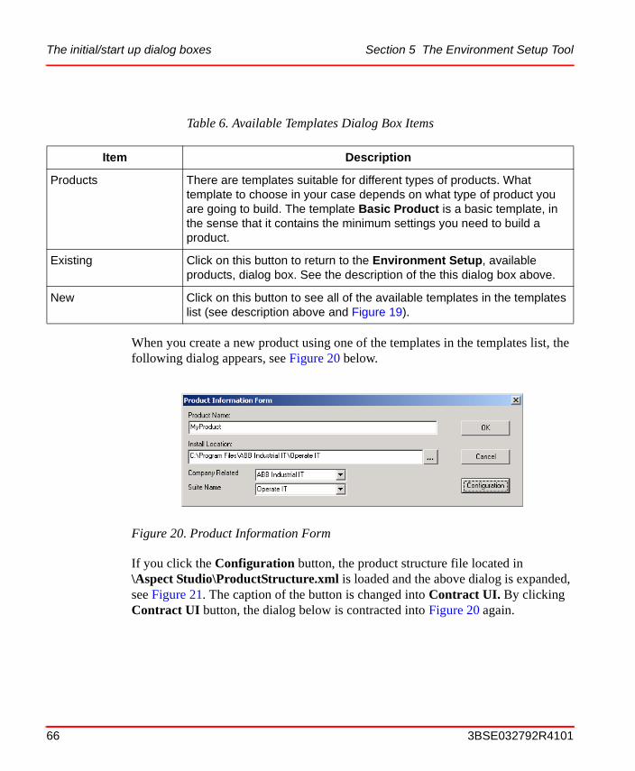
The initial/start up dialog boxes Section 5 The Environment Setup Tool
When you create a new product using one of the templates in the templates list, the following dialog appears, see Figure 20 below.
If you click the Configuration button, the product structure file located in\Aspect Studio\ProductStructure.xml is loaded and the above dialog is expanded, see Figure 21. The caption of the button is changed into Contract UI. By clicking Contract UI button, the dialog below is contracted into Figure 20 again.
Table 6. Available Templates Dialog Box Items
Item Description
Products There are templates suitable for different types of products. What template to choose in your case depends on what type of product you are going to build. The template Basic Product is a basic template, in the sense that it contains the minimum settings you need to build a product.
Existing Click on this button to return to the Environment Setup, available products, dialog box. See the description of the this dialog box above.
New Click on this button to see all of the available templates in the templates list (see description above and Figure 19).
Figure 20. Product Information Form
66 3BSE032792R4101
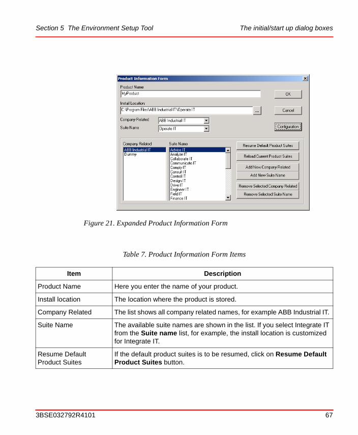
Section 5 The Environment Setup Tool The initial/start up dialog boxes
Figure 21. Expanded Product Information Form
Table 7. Product Information Form Items
Item Description
Product Name Here you enter the name of your product.
Install location The location where the product is stored.
Company Related The list shows all company related names, for example ABB Industrial IT.
Suite Name The available suite names are shown in the list. If you select Integrate IT from the Suite name list, for example, the install location is customized for Integrate IT.
Resume Default Product Suites
If the default product suites is to be resumed, click on Resume Default Product Suites button.
3BSE032792R4101 67

The initial/start up dialog boxes Section 5 The Environment Setup Tool
Reload Current Product Suites
If the product definition file is edited in an external editor, click on Reload Current Product Suites button to repopulate the product definition file into the dialog.
Add New Company Related
By clicking the Add New Company Related button, an input box is shown, where the new company related node is added into the product related product definition file.
Add New Suite Name By clicking the Add New Suite Name button, an input box is shown, where the new suite name is added into the selected company related node, which is then saved in the product related product definition file.
Remove Selected Company Related
By clicking the Remove Selected Company Related button, the selected company related node is to be removed from the product related product definition file.
Remove Selected Suite Name
By clicking the Remove Selected Suite Name button, the selected suite is to be removed from the selected company related node, the product related product definition file is then updated.
Table 7. Product Information Form Items (Continued)
Item Description
68 3BSE032792R4101
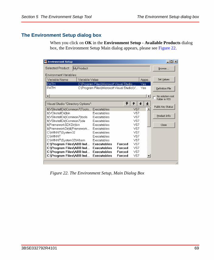
Section 5 The Environment Setup Tool The Environment Setup dialog box
The Environment Setup dialog box
When you click on OK in the Environment Setup - Available Products dialog box, the Environment Setup Main dialog appears, please see Figure 22.
Figure 22. The Environment Setup, Main Dialog Box
3BSE032792R4101 69
The Environment Setup dialog box Section 5 The Environment Setup Tool
Table 8. The Environment Setup, Main Dialog Box Items
Item Description
Selected Product Displays the product name you selected in the Environment Setup, available products, dialog box, Figure 18.
70 3BSE032792R4101
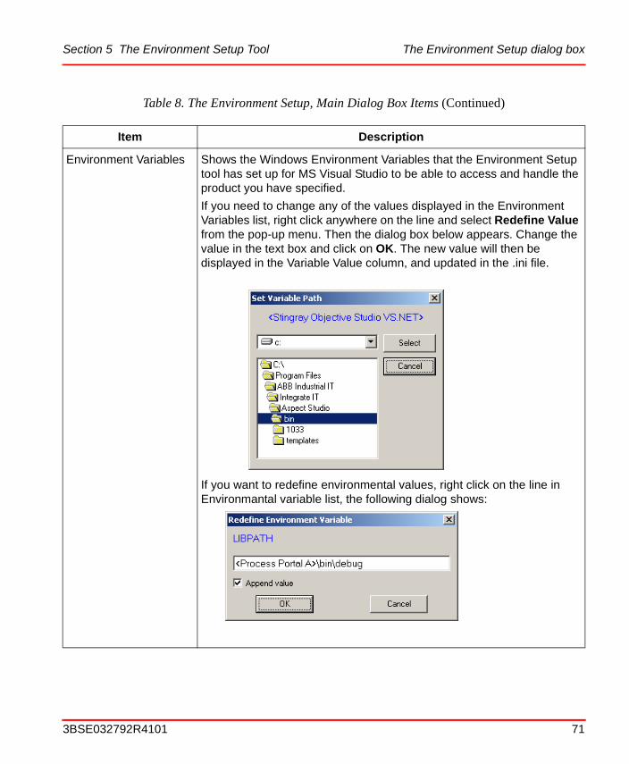
Section 5 The Environment Setup Tool The Environment Setup dialog box
Environment Variables Shows the Windows Environment Variables that the Environment Setup tool has set up for MS Visual Studio to be able to access and handle the product you have specified.
If you need to change any of the values displayed in the Environment Variables list, right click anywhere on the line and select Redefine Value from the pop-up menu. Then the dialog box below appears. Change the value in the text box and click on OK. The new value will then be displayed in the Variable Value column, and updated in the .ini file.
If you want to redefine environmental values, right click on the line in Environmantal variable list, the following dialog shows:
Table 8. The Environment Setup, Main Dialog Box Items (Continued)
Item Description
3BSE032792R4101 71
The Environment Setup dialog box Section 5 The Environment Setup Tool
Environmental Variables(cont.)
If you tick the Append value checkbox, the value will be appended at the end of the list of environment variable names for the current variable (PATH in the figure above).
If you for some reason want to view all of the Environment Variables set up on your system, not only for the product you are working with, then use either Start > Settings > Control Panel > System > tab Advanced > button Environment Variables, or the Set command in the Windows 2000 command window
Table 8. The Environment Setup, Main Dialog Box Items (Continued)
Item Description
72 3BSE032792R4101
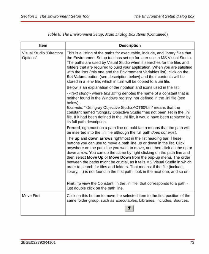
Section 5 The Environment Setup Tool The Environment Setup dialog box
Visual Studio “Directory Options”
This is a listing of the paths for executable, include, and library files that the Environment Setup tool has set up for later use in MS Visual Studio. The paths are used by Visual Studio when it searches for the files and folders that are required to build your application. When you are satisfied with the lists (this one and the Environment Variables list), click on the Set Values button (see description below) and their contents will be stored in a .env file, which in turn will be copied to a .ini file.
Below is an explanation of the notation and icons used in the list:
- <text string> where text string denotes the name of a constant that is neither found in the Windows registry, nor defined in the .ini file (see below). Example: “<Stingray Objective Studio>\OT60\bin” means that the constant named “Stingray Objective Studio “has not been set in the .ini file. If it had been defined in the .ini file, it would have been replaced by its full path description.
Forced, rightmost on a path line (in bold face) means that the path will be inserted into the .ini file although the full path does not exist.
The up and down arrows rightmost in the list heading bar. These buttons you can use to move a path line up or down in the list. Click anywhere on the path line you want to move, and then click on the up or down arrow. You can do the same by right clicking on the path line and then select Move Up or Move Down from the pop-up menu. The order between the paths might be crucial, as it tells MS Visual Studio in which order to search for files and folders. That means: if the file (include, library, ...) is not found in the first path, look in the next one, and so on.
Hint: To view the Constant, in the .ini file, that corresponds to a path - just double click on the path line.
Move First Click on this button to move the selected item to the first position of the same folder group, such as Executables, Libraries, Includes, Sources.
Table 8. The Environment Setup, Main Dialog Box Items (Continued)
Item Description
3BSE032792R4101 73

The Environment Setup dialog box Section 5 The Environment Setup Tool
Move Last Click on this button to move the selected item to the last position of the same folder group, such as Executables, Libraries, Includes, Sources.
Move Up/Down Use these buttons, below, to move a database up or down in the list.
Browse If you click on this button, the Environment Setup, available products, dialog box, shown in Figure 18, will appear. Select another product than the one you are working with at the moment, and its variables and paths will be displayed instead. If you are working with more than one product, this is a convenient way to switch between them.
Set Values When you click on this button, the values you see in the Environment Variables and Visual Studio “Directory Options” lists will be copied to the .ini file that corresponds to the current product. The name of the file will be ProductName.ini, for example MyProduct.ini.
In order to fetch the current values, right click on the Set Values button. Then select from which environment the values are to be fetched from, see figure below.
Initially, when you create your product, the values will be stored in a .env file, the name of which is ProductName.env. But the contents of this file will be copied to the ProductName.ini file. The reason for this is that it shall always be possible to retrieve the original settings.
The .env and .ini files are stored in the product’s SDK folder. For example: C:\Program Files\ABB Industrial IT\MyProductSDK.
When you click on this button, public key verification is also turned off.
Table 8. The Environment Setup, Main Dialog Box Items (Continued)
Item Description
74 3BSE032792R4101
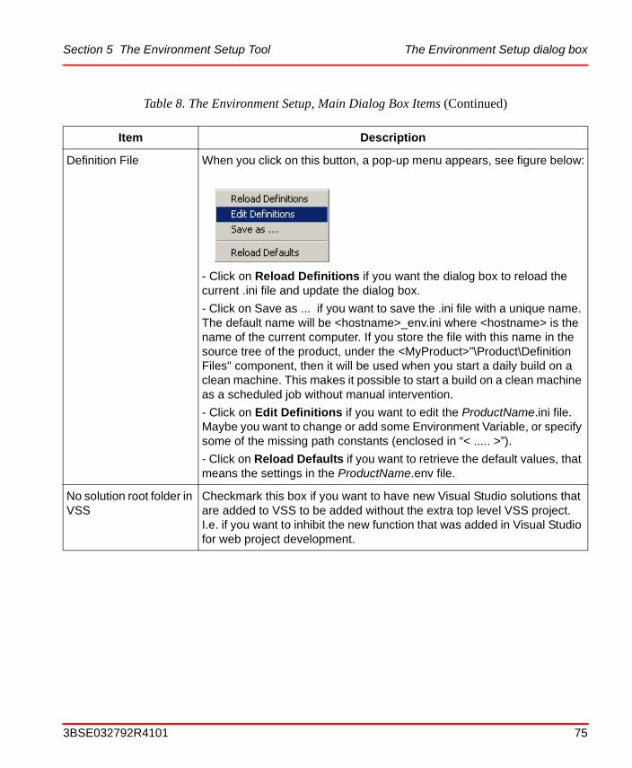
Section 5 The Environment Setup Tool The Environment Setup dialog box
Definition File When you click on this button, a pop-up menu appears, see figure below:
- Click on Reload Definitions if you want the dialog box to reload the current .ini file and update the dialog box.
- Click on Save as ... if you want to save the .ini file with a unique name. The default name will be <hostname>_env.ini where <hostname> is the name of the current computer. If you store the file with this name in the source tree of the product, under the <MyProduct>"\Product\Definition Files" component, then it will be used when you start a daily build on a clean machine. This makes it possible to start a build on a clean machine as a scheduled job without manual intervention.
- Click on Edit Definitions if you want to edit the ProductName.ini file. Maybe you want to change or add some Environment Variable, or specify some of the missing path constants (enclosed in “< ..... >”).
- Click on Reload Defaults if you want to retrieve the default values, that means the settings in the ProductName.env file.
No solution root folder in VSS
Checkmark this box if you want to have new Visual Studio solutions that are added to VSS to be added without the extra top level VSS project. I.e. if you want to inhibit the new function that was added in Visual Studio for web project development.
Table 8. The Environment Setup, Main Dialog Box Items (Continued)
Item Description
3BSE032792R4101 75
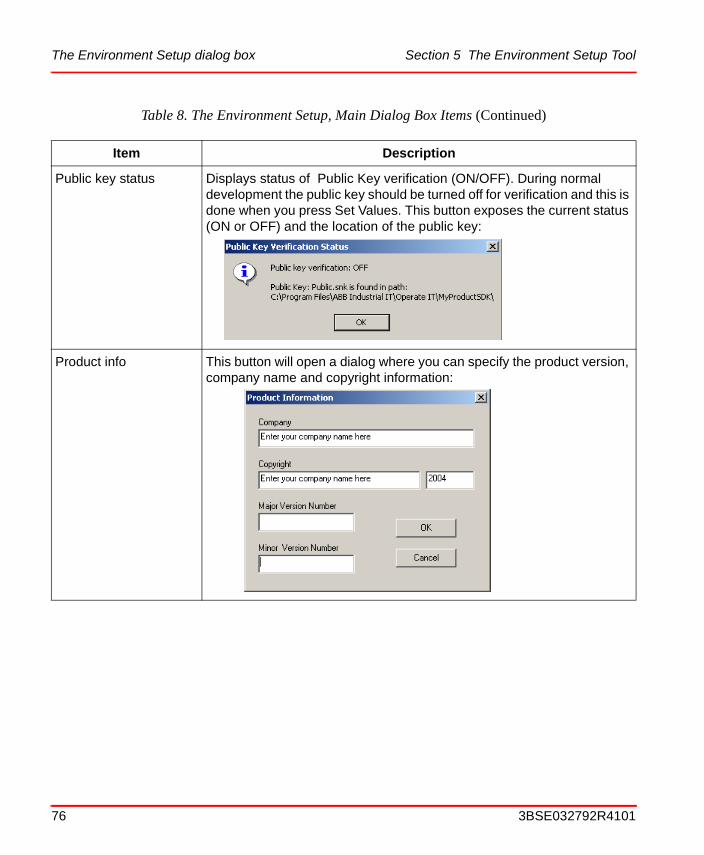
The Environment Setup dialog box Section 5 The Environment Setup Tool
Public key status Displays status of Public Key verification (ON/OFF). During normal development the public key should be turned off for verification and this is done when you press Set Values. This button exposes the current status (ON or OFF) and the location of the public key:
Product info This button will open a dialog where you can specify the product version, company name and copyright information:
Table 8. The Environment Setup, Main Dialog Box Items (Continued)
Item Description
76 3BSE032792R4101
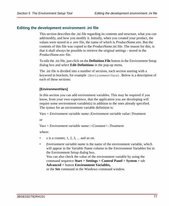
Section 5 The Environment Setup Tool Editing the development environment .ini file
Editing the development environment .ini file
This section describes the .ini file regarding its contents and structure, what you can add/modify, and how you modify it. Initially, when you created your product, the values were stored in a .env file, the name of which is ProductName.env. But the contents of this file was copied to the ProductName.ini file. The reason for this, is that it shall always be possible to retrieve the original settings - stored in the ProductName.env file.
To edit the .ini file, just click on the Definition File button in the Environment Setup dialog box and select Edit Definitions in the pop-up menu.
The .ini file is divided into a number of sections, each section starting with a keyword in brackets, for example [EnvironmentVars]. Below is a description of each of these sections:
[EnvironmentVars]
In this section you can add environment variables. This may be required if you know, from your own experience, that the application you are developing will require some environment variable(s) in addition to the ones already specified.The syntax for an environment variable definition is:
Varx = Environment variable name::Environment variable value::Treatment
or
Varx = Environment variable name::<Constant>::Treatment
where:
• x is a counter, 1, 2, 3, ... and so on.
• Environment variable name is the name of the environment variable, which will appear in the Variable Name column in the Environment Variables list in the Environment Setup dialog box. You can also check the value of the environment variable by using the command sequence Start > Settings > Control Panel > System > tab Advanced > button Environment Variables, or the Set command in the Windows command window.
3BSE032792R4101 77
Editing the development environment .ini file Section 5 The Environment Setup Tool
• Environment variable value is the value that shall be assigned to Environment variable name, that means the value that will appear in the Variable Value column in the Environment Variables list in the Environment Setup dialog box. And also can be checked as described above.
• Constant enclosed in angle-brackets. This constant will, for example in section [FoundInLocalMachine], be set to the name of a product’s (for example Visual Basic’s) parent directory. And the environment variable with the name Environment variable name will then get this value. See also the description of the [Constants] section below.
• Treatment the way the environment variable value shall be inserted to the value list for the environment variable at hand. There are two alternatives:
– APPEND insert the value at the end of the current value list for the environment variable. The values in the list are separated from each other by semicolons.
– PLAIN remove the current values in the list and replace them with Environment variable value.
Example 1: Var1 = PATH::<Microsoft Visual Basic>::APPEND
In this case, “Microsoft Visual Basic” is a constant, to be set to the name of Visual Basic’s parent directory, stored in the Registry. The value of the ProductDir variable in the Registry will, in section [FoundInLocalMachine], be fetched and appended to the PATH environment variable.
Example 2: Var1 = MyEnvVar::QRS789::PLAIN
In this case, a new environment variable, named MyEnvVar, will be created and set to QRS789.
[Constants]
The reason for using constants, is to simplify the specification of all the path names for the executable, include, library, and source files that are specified further down in the .ini file (see description below). Instead of the full path names, the constant names are used.
Be cautious when you use PLAIN, as it will erase all the previous values of the environment variable.
78 3BSE032792R4101
Section 5 The Environment Setup Tool Editing the development environment .ini file
Then - before presentation in the Environment Setup dialog box - these constants are replaced by the corresponding, complete path values found in the Registry. Note that the constants (text strings) declared in this section are only visible and used within the .ini file. Which means that you will not see them in any of the Environment Setup dialog boxes. The constants normally represent parent directories for different products. Such a parent directory in turn, holds main entry information about the product. For example, the ProductDir environment variable value, which is the top level directory path to the product at hand.
The syntax for a constant definition is:
Varx = <Constant>, where x=1, 2, 3, ...and so on.
Example: Var6 = <Microsoft Visual Basic>
In the Registry, the Visual Basic directory path contains the ProductDir variable value at some level, and this value can be, for example:C:\Program Files\Microsoft Visual Studio\VB98. This full description will then be presented by the Environment Setup dialog box, and be accessible to MS Visual Studio.
[FoundInLocalMachine]
In this section, some of the constants declared in the [Constants] section get their values. The values of the constants given in this section will be used when searching in the HKEY_LOCAL_MACHINE Registry folder. The syntax used in this section is:
<Constant> = Registry directory path:Registry value
Example: <Microsoft Visual Basic> = SOFTWARE\Microsoft\ VisualStudio.net\Setup\Microsoft Visual Basic:ProductDir
The Registry value name in the example, that is ProductDir, holds the value of the path to the Visual Basic parent directory, for example: C:\Program Files\Microsoft\Visual Studio\VB98.
This path value, will then be inserted instead of the <Microsoft Visual Basic> constant wherever it is used in the [EnvironmentVars], [Executables], [Includes], [Libraries], and [Sources] sections, see descriptions above and below.
3BSE032792R4101 79

Editing the development environment .ini file Section 5 The Environment Setup Tool
[FoundInCurrentUser]
Same mechanism as for section [FoundInLocalMachine] above, but for values in Registry folder HKEY_CURRENT_USER.
[FoundInWindowsInstaller]
In this section, some of the constants declared in the [Constants] section get their
values. The values of the constants given in this section will be translated by using the Microsoft Installer Application Programmer Interface (API). The syntax used in this section is:
< Constant> = My product name
Example: <Paint Shop> = Paint Shop Pro 7
The windows installer API will return the path to the root where the product "Paint Shop Pr0 7" is installed e.g. C:\Program Files\Jasc Software Inc.
[FoundInABBProducts]
Same mechanism as for section [FoundInWindowsInstaller] above but with the following addition to the syntax:
< Constant> = My product name::option
Example:
<PPA> = Process Portal A::RUNTIME
<PPA SDK> = Process Portal A::SDK
<PPA TEST> = Process Portal A::TEST
The windows installer API will return the path to the root where the product "Process Portal A" is installed. This value is then used for creating the values on the specified constants as follows (example):
<PPA> = C:\Program Files\ABB Industrial IT\Operate IT\Process Portal A
<PPA SDK> = C:\Program Files\ABB Industrial IT\Operate IT\Process Portal ASDK
80 3BSE032792R4101
Section 5 The Environment Setup Tool Editing the development environment .ini file
<PPA TEST> = C:\Program Files\ABB Industrial IT\Operate IT\Process Portal ATEST
[UndefinedInReg]
This is the place where you insert descriptions of Constants which are not stored in the Registry, but which are required to complete one or more path description.
[Executables], [Includes], [Libraries], [Sources] and [Assemblies]
Those sections specify the paths that will appear in the path list in the Environment Setup dialog box, and be accessible from Visual Studio. They will be listed in the same order as they are specified in this section. The syntax is:
Varx = <Constant>\sub-folder 1\sub-folder 2\...::Force or NoForce...
where:
• Constant, described above
• \sub-folder 1\sub-folder 2\..., the folders that will be appended to the “Constant” path.
• Force/NoForce. “Force” means that the path will be inserted into the .ini file even if the path does not exist. “NoForce” means that the path will not be inserted if it does not exist.
Example: Var2 = <Microsoft Visual C++>\bin::NoForce::VS7
If the found Registry value for Microsoft Visual C++’s parent directory is C:\Program Files\Microsoft Visual Studio\VC98
then the path C:\Program Files\Microsoft Visual Studio\VC98\bin
will appear as Executable path description number 2 in the Environment Setup dialog box, and consequently in the .ini file.
[Assemblies]
Visual Studio .NET can be configured to search for managed assemblies (.NET assemblies) in order to resolve dependencies during the build process.
3BSE032792R4101 81
Editing the development environment .ini file Section 5 The Environment Setup Tool
Example:Var1 = <Simple Basic Product>\bin::Force::VS7
Var2 = <Simple Basic Product>\bin\debug::Force::VS7
A path defined in this section will generate a new registry key under the HKLM\Software\Microsoft\.NETFramework\AssemblyFolders key.
[Public Key]
If this section is present it instruct the enviroment setup tool to disable strong name verification for the product when you press Set Values.
Example:Var1 = <Strong Name Public Key>::NoForce::VS7
82 3BSE032792R4101
Section 6 The Aspect Objects AppWizard andthe Class Wizard
What you can do with the Aspect Objects AppWizardThe purpose of the Aspect Objects AppWizard is to simplify the creation of Aspect Systems, System Extensions, Services and Test projects. Then, when you have created an Aspect System Project, you can use the Class Wizard to create templates for the ASOs (Aspect System Objects) you need. That is: Aspect View, Aspect Page, Aspect Data, and Aspect Verb ASOs.
Implementing Aspect Systems is the primary way to integrate functionality into your IndustrialIT system. After you have registered an Aspect System in the Aspect Directory, you can use the Operator Workplace and/or the Plant Explorer to operate on or create aspects which belong to the Aspect System.
A System Extension, or a System Product Extension, consists of one or more applications which are bundled as an extension to one or more existing System Products. Example: The 800xA for Advant Master is a System Extension to 800xA System. By using the Aspect Objects AppWizard, you can build your own System Extensions.
With the Aspect Objects AppWizard, you can also create a template for a Simple Service or a Socket Service. A Simple Service is an executable without any connection to a client, whereas a Socket Service supports both a server and a client that communicate with each other using a socket based protocol.
A Test Project is a project to which you can add test components which fit into ABB’s framework for automated tests. Each part of the 800xA System is tested through such automated tests. When you have created your test project, you can add test components through the Class Wizard. A test component is a COM object that holds a test suite, that is, a number of test cases. The wizard creates a complete example, containing one test case, to help the programmer to get started.
3BSE032792R4101 83

The Aspect Objects AppWizard User Interface Section 6 The Aspect Objects AppWizard and the
The Aspect Objects AppWizard User InterfaceThis section describes how to create an Aspect System, a System Extension, a Simple Service and an Afw Test Project using the Aspect Objects AppWizard.
Prior to running the Aspect Objects AppWizard, the MyProduct environment must be created with the Environment Setup tool, and the ref_src tree must be copied to src by the Build Manager. See Section 5, The Environment Setup Tool and Section 7, The Build Manager.
The AppWizard creates Visual Studio project skeletons. The projects will have a correct setup for Aspect System programming. For example, Unicode will be selected.
After creation of the projects, the directory tree should be similar to Figure 23 below.
Below is a description of the user interfaces (GUIs) you will face when you start up the Aspect Objects AppWizard. Follow the steps below:
1. Start Microsoft Visual Studio.NET.
Figure 23. Example of Directory Tree
84 3BSE032792R4101
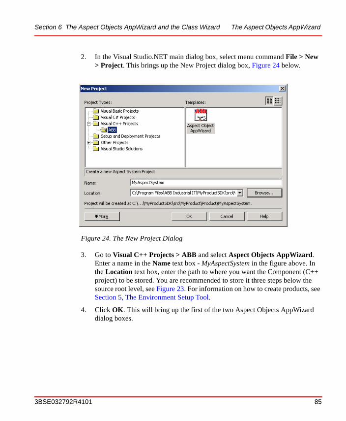
Section 6 The Aspect Objects AppWizard and the Class Wizard The Aspect Objects AppWizard
2. In the Visual Studio.NET main dialog box, select menu command File > New > Project. This brings up the New Project dialog box, Figure 24 below.
3. Go to Visual C++ Projects > ABB and select Aspect Objects AppWizard. Enter a name in the Name text box - MyAspectSystem in the figure above. In the Location text box, enter the path to where you want the Component (C++ project) to be stored. You are recommended to store it three steps below the source root level, see Figure 23. For information on how to create products, see Section 5, The Environment Setup Tool.
4. Click OK. This will bring up the first of the two Aspect Objects AppWizard dialog boxes.
Figure 24. The New Project Dialog
3BSE032792R4101 85
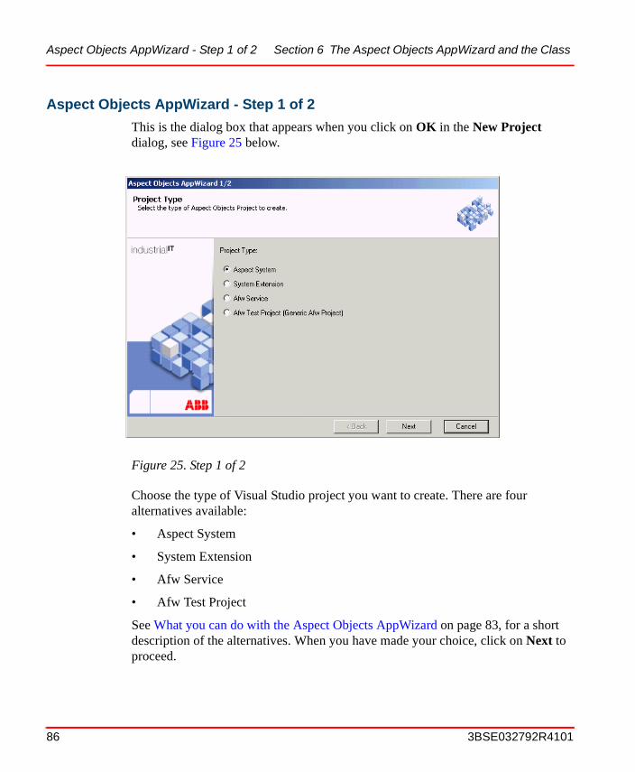
Aspect Objects AppWizard - Step 1 of 2 Section 6 The Aspect Objects AppWizard and the Class
Aspect Objects AppWizard - Step 1 of 2
This is the dialog box that appears when you click on OK in the New Project dialog, see Figure 25 below.
Choose the type of Visual Studio project you want to create. There are four alternatives available:
• Aspect System
• System Extension
• Afw Service
• Afw Test Project
See What you can do with the Aspect Objects AppWizard on page 83, for a short description of the alternatives. When you have made your choice, click on Next to proceed.
Figure 25. Step 1 of 2
86 3BSE032792R4101
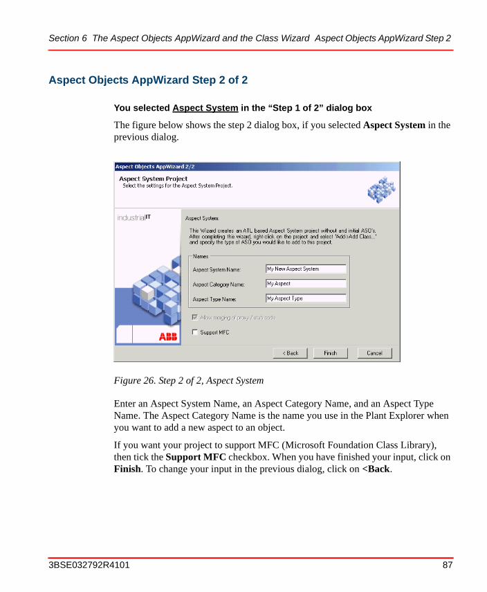
Section 6 The Aspect Objects AppWizard and the Class Wizard Aspect Objects AppWizard Step 2
Aspect Objects AppWizard Step 2 of 2
You selected Aspect System in the “Step 1 of 2” dialog box
The figure below shows the step 2 dialog box, if you selected Aspect System in the previous dialog.
Enter an Aspect System Name, an Aspect Category Name, and an Aspect Type Name. The Aspect Category Name is the name you use in the Plant Explorer when you want to add a new aspect to an object.
If you want your project to support MFC (Microsoft Foundation Class Library), then tick the Support MFC checkbox. When you have finished your input, click on Finish. To change your input in the previous dialog, click on <Back.
Figure 26. Step 2 of 2, Aspect System
3BSE032792R4101 87
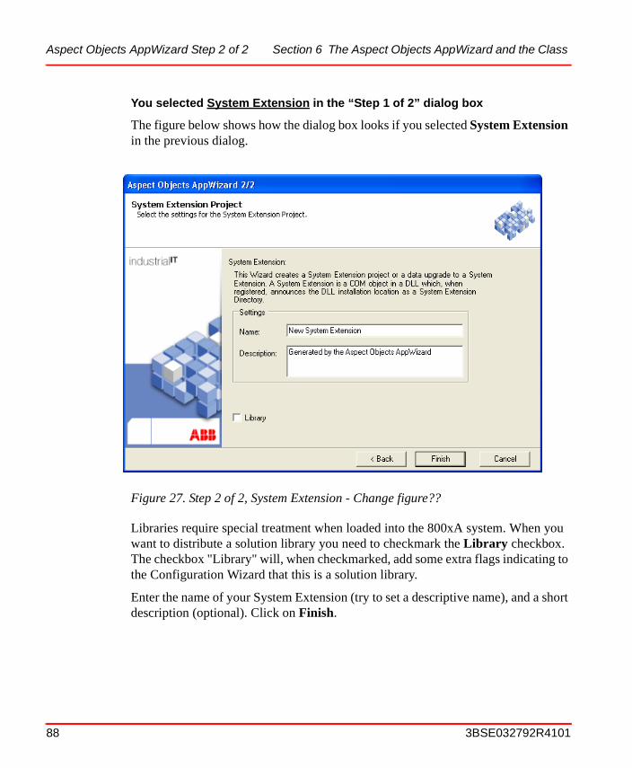
Aspect Objects AppWizard Step 2 of 2 Section 6 The Aspect Objects AppWizard and the Class
You selected System Extension in the “Step 1 of 2” dialog box
The figure below shows how the dialog box looks if you selected System Extension in the previous dialog.
Libraries require special treatment when loaded into the 800xA system. When you want to distribute a solution library you need to checkmark the Library checkbox. The checkbox "Library" will, when checkmarked, add some extra flags indicating to the Configuration Wizard that this is a solution library.
Enter the name of your System Extension (try to set a descriptive name), and a short description (optional). Click on Finish.
Figure 27. Step 2 of 2, System Extension - Change figure??
88 3BSE032792R4101
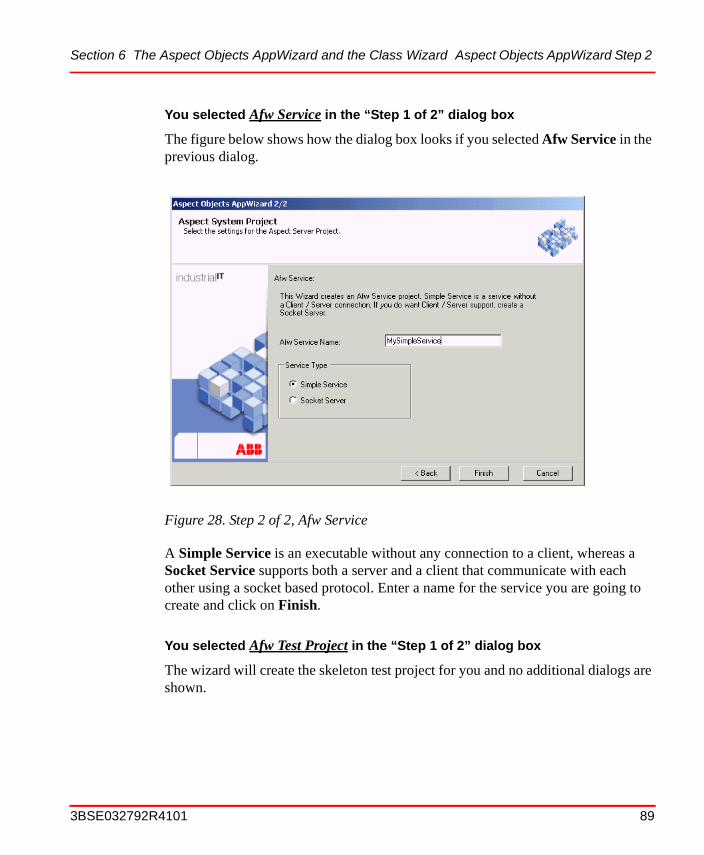
Section 6 The Aspect Objects AppWizard and the Class Wizard Aspect Objects AppWizard Step 2
You selected Afw Service in the “Step 1 of 2” dialog box
The figure below shows how the dialog box looks if you selected Afw Service in the previous dialog.
A Simple Service is an executable without any connection to a client, whereas a Socket Service supports both a server and a client that communicate with each other using a socket based protocol. Enter a name for the service you are going to create and click on Finish.
You selected Afw Test Project in the “Step 1 of 2” dialog box
The wizard will create the skeleton test project for you and no additional dialogs are shown.
Figure 28. Step 2 of 2, Afw Service
3BSE032792R4101 89
What you can do with the Class Wizard Section 6 The Aspect Objects AppWizard and the Class
What you can do with the Class WizardSo far in this section we have discussed the tools you use to create different types of projects - Aspect System Project, Service Project, and so on. Next step is to introduce the Class Wizard. Using this tool, you can create different types of so called ASOs (Aspect System Objects), which together form an Aspect Type. For the ASOs, there are currently a number of Active Template Library (ATL) objects you can choose from:
• Aspect Data ASOThis ASO handles all data storage and most of the semantics for the aspect.
• Aspect View ASOThis ATL object interacts with the Data ASO and implements a view ASO that can be displayed in the workplace. This ASO implements UI functionality of the aspect system.
• Aspect Verb ASOTo be used when adding verb items to the context menus of the workplace. It handles dispatching of verb execution requests to the correct method in the Data ASO. Note that you may not need a separate verb ASO. If that is the case, you can just move the relevant code into the Data ASO.
• Aspect Page ASOThis ATL object is used when building standard configuration (tabbed) dialogs. This includes standardized buttons and behavior for “Apply”, “Cancel” and “Help”.
The Class Wizard User InterfaceBelow is a description of the user interfaces you use to create the different types of the ASOs mentioned above.
90 3BSE032792R4101
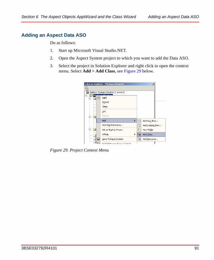
Section 6 The Aspect Objects AppWizard and the Class Wizard Adding an Aspect Data ASO
Adding an Aspect Data ASO
Do as follows:
1. Start up Microsoft Visual Studio.NET.
2. Open the Aspect System project to which you want to add the Data ASO.
3. Select the project in Solution Explorer and right click to open the context menu. Select Add > Add Class, see Figure 29 below.
Figure 29. Project Context Menu
3BSE032792R4101 91
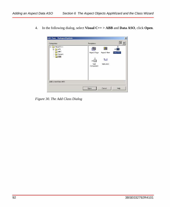
Adding an Aspect Data ASO Section 6 The Aspect Objects AppWizard and the Class Wizard
4. In the following dialog, select Visual C++ > ABB and Data ASO, click Open.
Figure 30. The Add Class Dialog
92 3BSE032792R4101
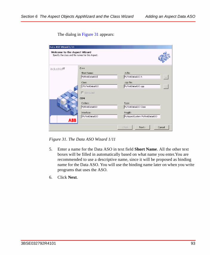
Section 6 The Aspect Objects AppWizard and the Class Wizard Adding an Aspect Data ASO
The dialog in Figure 31 appears:
5. Enter a name for the Data ASO in text field Short Name. All the other text boxes will be filled in automatically based on what name you enter.You are recommended to use a descriptive name, since it will be proposed as binding name for the Data ASO. You will use the binding name later on when you write programs that uses the ASO.
6. Click Next.
Figure 31. The Data ASO Wizard 1/11
3BSE032792R4101 93
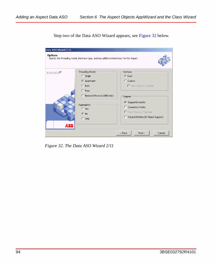
Adding an Aspect Data ASO Section 6 The Aspect Objects AppWizard and the Class Wizard
Step two of the Data ASO Wizard appears, see Figure 32 below.
Figure 32. The Data ASO Wizard 2/11
94 3BSE032792R4101
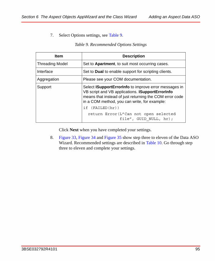
Section 6 The Aspect Objects AppWizard and the Class Wizard Adding an Aspect Data ASO
7. Select Options settings, see Table 9.
Click Next when you have completed your settings.
8. Figure 33, Figure 34 and Figure 35 show step three to eleven of the Data ASO Wizard. Recommended settings are described in Table 10. Go through step three to eleven and complete your settings.
Table 9. Recommended Options Settings
Item Description
Threading Model Set to Apartment, to suit most occurring cases.
Interface Set to Dual to enable support for scripting clients.
Aggregation Please see your COM documentation.
Support Select ISupportErrorInfo to improve error messages in VB script and VB applications. ISupportErrorInfo means that instead of just returning the COM error code in a COM method, you can write, for example:
if (FAILED(hr))
return Error(L”Can not open selected file”, GUID_NULL, hr);
3BSE032792R4101 95
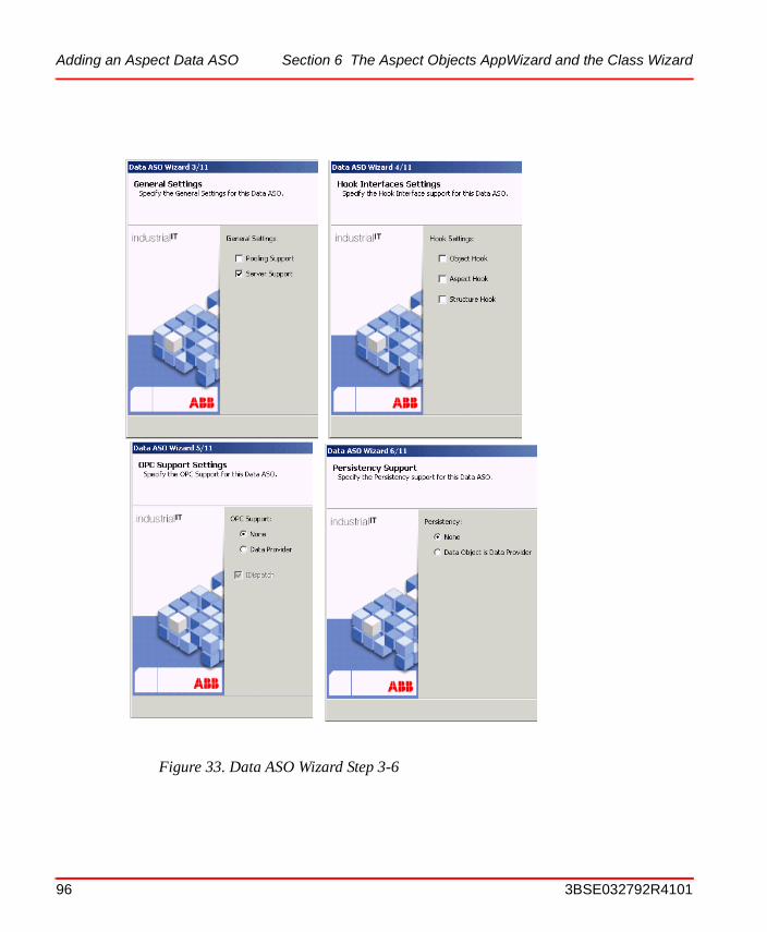
Adding an Aspect Data ASO Section 6 The Aspect Objects AppWizard and the Class Wizard
Figure 33. Data ASO Wizard Step 3-6
96 3BSE032792R4101
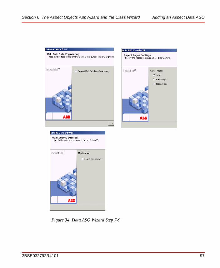
Section 6 The Aspect Objects AppWizard and the Class Wizard Adding an Aspect Data ASO
Figure 34. Data ASO Wizard Step 7-9
3BSE032792R4101 97
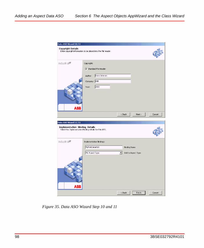
Adding an Aspect Data ASO Section 6 The Aspect Objects AppWizard and the Class Wizard
Figure 35. Data ASO Wizard Step 10 and 11
98 3BSE032792R4101

Section 6 The Aspect Objects AppWizard and the Class Wizard Adding an Aspect Data ASO
Table 10. Recommended Settings Step 3-9
Item Description
General Settings • Pooling SupportThis is an advanced setting. Aspect pooling is aimed to be used in order to minimize the number of CoCreateInstance operations performed on aspect objects. If you specify that your aspect object is to be pooled, then you will be called through the Clear call when the aspect object is put in the pool, and called through Init when it is used again. Using aspect pooling is not recommend unless it is either very costly to create the COM object, or if you use a large number (thousands) of ASOs of this type.
• Server SupportIf you select Server Aspect, you will get an ASO which can run continuously with supervision in the context of a service. Server aspects are “normal” aspects, developed in the same way as any other aspects. The aspect needs to provide one special interface to indicate that it can be executed within a server context. The processes, services, which run the server aspects are called Server Aspect Controllers (SACs).
Hook Settings You can select Hook interfaces for Object Hook, Aspect Hook, and/or Structure Hook if the Aspect System shall perform some action when changes occur, on either the object, the aspect, or the structure. A “change” can be a create, delete, or change of the specific item.
OPC Support Select Data Provider if the Aspect is to be used as a data provider for OPC.
Persistency Select Data Object if you need persistency support.
XML Bulk Data Engineering
Adds skeleton methods for Bulk Data management of the Aspect Data.
Aspect Pages If you want to use one or more aspect pages, then select Single Page or Tabbed Page. For a single custom view, select None.
Note that you must add at least one Aspect Page ATL Object if you select “Single Page” or “Tabbed”. An Aspect Page is a standard page (window) for Aspects, containing an OK, Cancel, and Apply button.
3BSE032792R4101 99
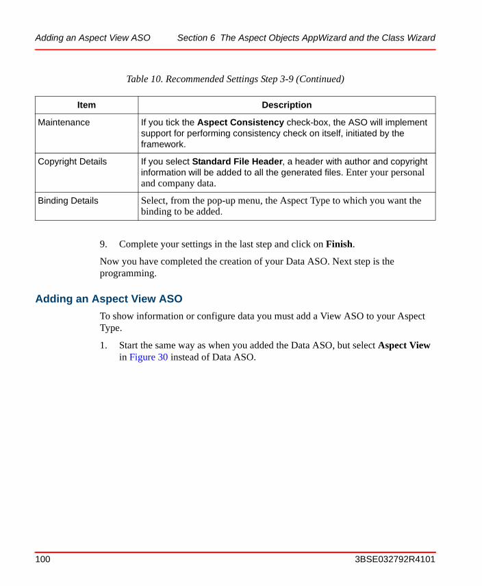
Adding an Aspect View ASO Section 6 The Aspect Objects AppWizard and the Class Wizard
9. Complete your settings in the last step and click on Finish.
Now you have completed the creation of your Data ASO. Next step is the programming.
Adding an Aspect View ASO
To show information or configure data you must add a View ASO to your Aspect Type.
1. Start the same way as when you added the Data ASO, but select Aspect View in Figure 30 instead of Data ASO.
Maintenance If you tick the Aspect Consistency check-box, the ASO will implement support for performing consistency check on itself, initiated by the framework.
Copyright Details If you select Standard File Header, a header with author and copyright information will be added to all the generated files. Enter your personal and company data.
Binding Details Select, from the pop-up menu, the Aspect Type to which you want the binding to be added.
Table 10. Recommended Settings Step 3-9 (Continued)
Item Description
100 3BSE032792R4101
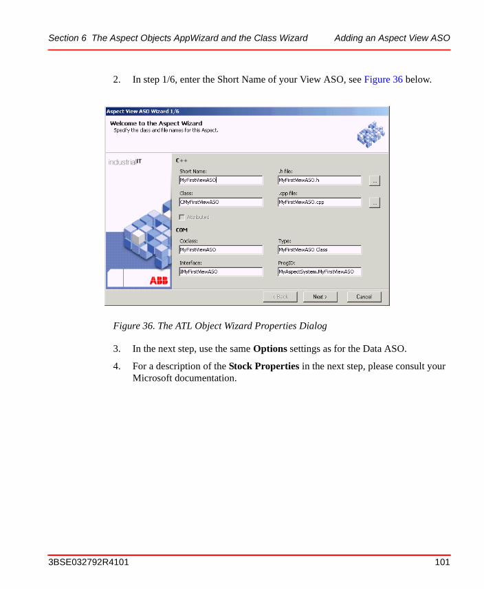
Section 6 The Aspect Objects AppWizard and the Class Wizard Adding an Aspect View ASO
2. In step 1/6, enter the Short Name of your View ASO, see Figure 36 below.
3. In the next step, use the same Options settings as for the Data ASO.
4. For a description of the Stock Properties in the next step, please consult your Microsoft documentation.
Figure 36. The ATL Object Wizard Properties Dialog
3BSE032792R4101 101

Adding an Aspect Page ASO Section 6 The Aspect Objects AppWizard and the Class Wizard
5. You are strongly recommended to select Resize support in the next dialog, see
Figure 37. This because your view will then scale/resize in a proper way when you resize the host window.
6. The remaining two dialogs are identical with the last two dialogs for the Data ASO Wizard.
Adding an Aspect Page ASO
If you selected Single page or Tabbed for the Data ASO, then you must add at least one Aspect page. The dialog boxes for an Aspect page ASO are almost identical to the dialog boxes for an Aspect View ASO. The only difference is that you must set a name to the tab.
Figure 37. The Aspect Page Dialog
102 3BSE032792R4101
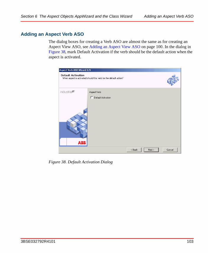
Section 6 The Aspect Objects AppWizard and the Class Wizard Adding an Aspect Verb ASO
Adding an Aspect Verb ASO
The dialog boxes for creating a Verb ASO are almost the same as for creating an Aspect View ASO, see Adding an Aspect View ASO on page 100. In the dialog in Figure 38, mark Default Activation if the verb should be the default action when the aspect is activated.
Figure 38. Default Activation Dialog
3BSE032792R4101 103
Adding an Aspect Verb ASO Section 6 The Aspect Objects AppWizard and the Class Wizard
104 3BSE032792R4101
Section 7 The Build Manager
The Build manager is a part of the Aspect Studio. Running the Build Manager tool is, normally, the second step (after Environment Setup) in the process of building an application package - no matter if it is the 800xA System basic software you are working with or some customer specific application.
During the development process, you will now and then have to return to the Build Manager, such as:
• When the product structure (your source tree) is changed, due to new components being added, and you need to re-configure the build description files (build.abc files), or the source inventory file (FilesSDK.abc).
• Creation of baselines in VSS
• Defining and starting sequential builds of your product.
What you can do with the Build ManagerThe Build Manager is a software development tool, included in the Aspect Studio, which mainly handles version control and build management of families of Microsoft Visual Studio components. The key functionality of the Build Manager is its capability to handle the baseline creation and build of components in a batch oriented way. Matters like:
• Which VSS (Visual SourceSafe) repositories are involved,
• Which baseline is to be created or used,
• Which build operations are to be performed,
• In which order the different baseline and build operations shall be carried out,
can be controlled by the user (typically a product or project integrator or a developer of software components) through the Build Manager's user interface.
3BSE032792R4101 105
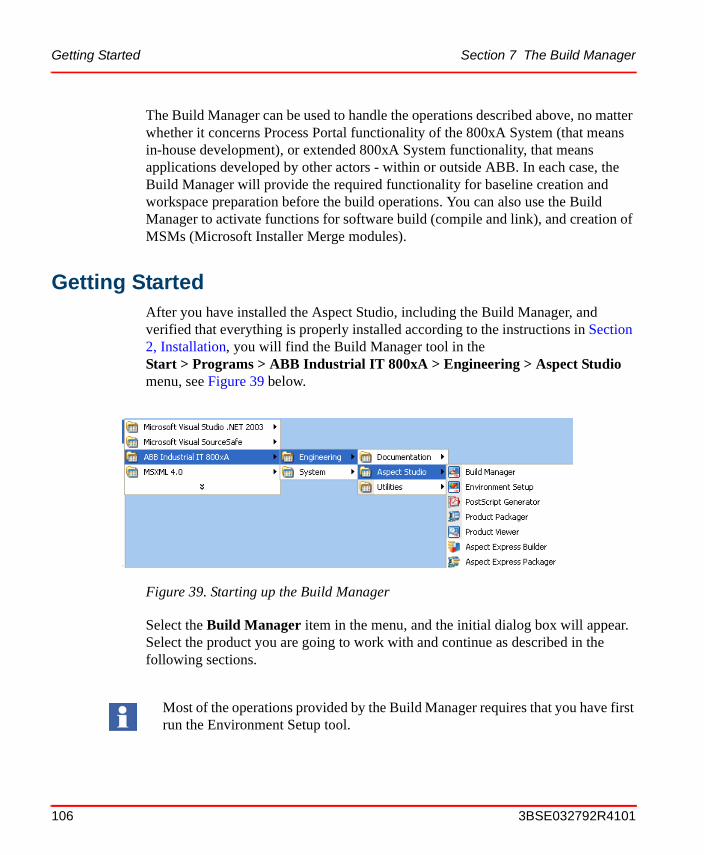
Getting Started Section 7 The Build Manager
The Build Manager can be used to handle the operations described above, no matter whether it concerns Process Portal functionality of the 800xA System (that means in-house development), or extended 800xA System functionality, that means applications developed by other actors - within or outside ABB. In each case, the Build Manager will provide the required functionality for baseline creation and workspace preparation before the build operations. You can also use the Build Manager to activate functions for software build (compile and link), and creation of MSMs (Microsoft Installer Merge modules).
Getting StartedAfter you have installed the Aspect Studio, including the Build Manager, and verified that everything is properly installed according to the instructions in Section 2, Installation, you will find the Build Manager tool in the Start > Programs > ABB Industrial IT 800xA > Engineering > Aspect Studio menu, see Figure 39 below.
Select the Build Manager item in the menu, and the initial dialog box will appear. Select the product you are going to work with and continue as described in the following sections.
Figure 39. Starting up the Build Manager
Most of the operations provided by the Build Manager requires that you have first run the Environment Setup tool.
106 3BSE032792R4101
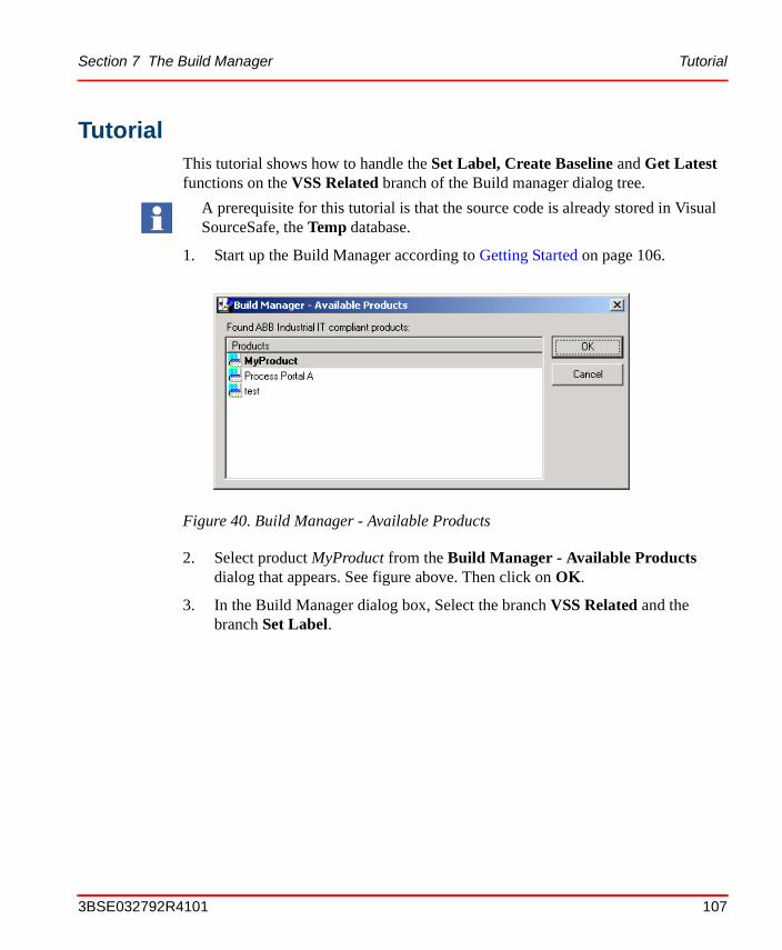
Section 7 The Build Manager Tutorial
TutorialThis tutorial shows how to handle the Set Label, Create Baseline and Get Latest functions on the VSS Related branch of the Build manager dialog tree.
1. Start up the Build Manager according to Getting Started on page 106.
2. Select product MyProduct from the Build Manager - Available Products dialog that appears. See figure above. Then click on OK.
3. In the Build Manager dialog box, Select the branch VSS Related and the branch Set Label.
A prerequisite for this tutorial is that the source code is already stored in Visual SourceSafe, the Temp database.
Figure 40. Build Manager - Available Products
3BSE032792R4101 107
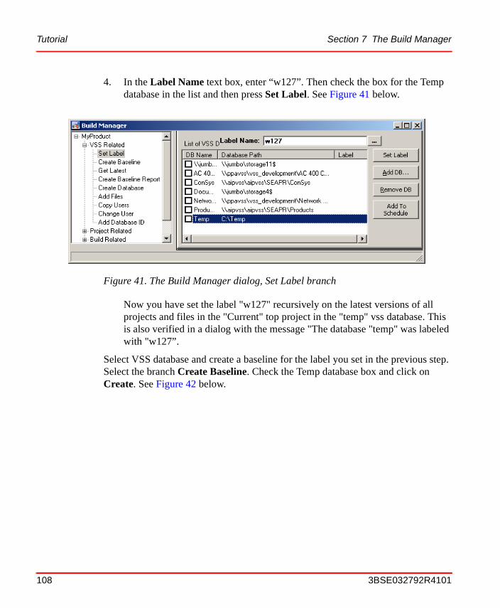
Tutorial Section 7 The Build Manager
4. In the Label Name text box, enter “w127”. Then check the box for the Temp database in the list and then press Set Label. See Figure 41 below.
Now you have set the label "w127" recursively on the latest versions of all projects and files in the "Current" top project in the "temp" vss database. This is also verified in a dialog with the message "The database "temp" was labeled with "w127”.
Select VSS database and create a baseline for the label you set in the previous step. Select the branch Create Baseline. Check the Temp database box and click on Create. See Figure 42 below.
Figure 41. The Build Manager dialog, Set Label branch
108 3BSE032792R4101

Section 7 The Build Manager Tutorial
An Output Message Dialog box appears with the message that the database was shared and pinned, see Figure 43 below.
Figure 42. The Build Manager dialog, Create Baseline branch
Figure 43. Output Message
3BSE032792R4101 109
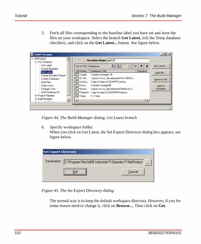
Tutorial Section 7 The Build Manager
5. Fetch all files corresponding to the baseline label you have set and store the files on your workspace. Select the branch Get Latest, tick the Temp database checkbox, and click on the Get Latest... button. See figure below.
6. Specify workspace folder.When you click on Get Latest, the Set Export Directory dialog box appears, see figure below.
The normal way is to keep the default workspace directory. However, if you for some reason need to change it, click on Browse.... Then click on Get.
Figure 44. The Build Manager dialog, Get Latest branch
Figure 45. The Set Export Directory dialog
110 3BSE032792R4101
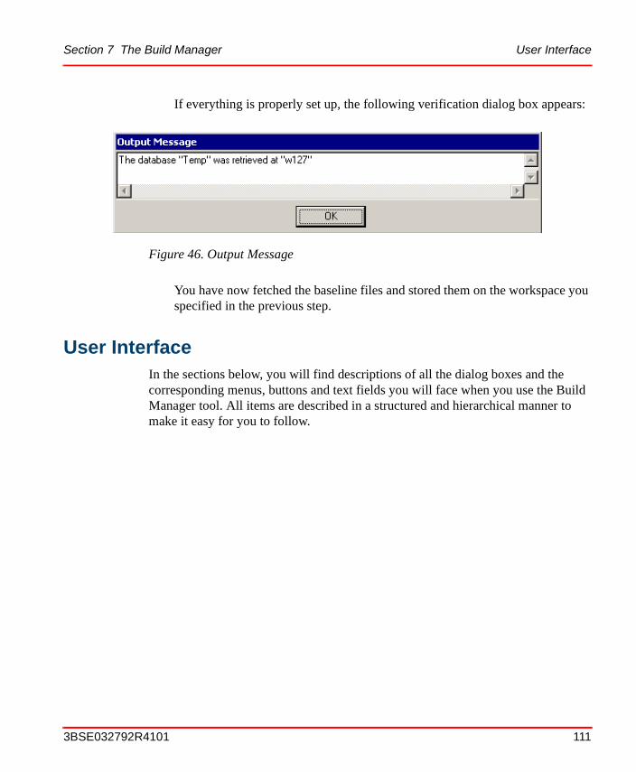
Section 7 The Build Manager User Interface
If everything is properly set up, the following verification dialog box appears:
You have now fetched the baseline files and stored them on the workspace you specified in the previous step.
User InterfaceIn the sections below, you will find descriptions of all the dialog boxes and the corresponding menus, buttons and text fields you will face when you use the Build Manager tool. All items are described in a structured and hierarchical manner to make it easy for you to follow.
Figure 46. Output Message
3BSE032792R4101 111
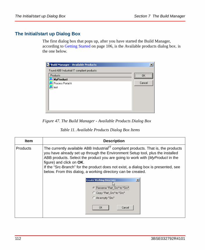
The Initial/start up Dialog Box Section 7 The Build Manager
The Initial/start up Dialog Box
The first dialog box that pops up, after you have started the Build Manager, according to Getting Started on page 106, is the Available products dialog box. is the one below.
Figure 47. The Build Manager - Available Products Dialog Box
Table 11. Available Products Dialog Box Items
Item Description
Products The currently available ABB IndustrialIT compliant products. That is, the products you have already set up through the Environment Setup tool, plus the installed ABB products. Select the product you are going to work with (MyProduct in the figure) and click on OK.If the “Src-Branch” for the product does not exist, a dialog box is presented, see below. From this dialog, a working directory can be created.
112 3BSE032792R4101
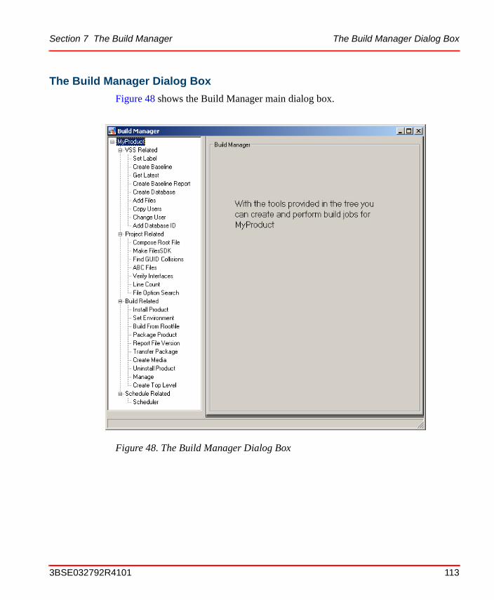
Section 7 The Build Manager The Build Manager Dialog Box
The Build Manager Dialog Box
Figure 48 shows the Build Manager main dialog box.
Figure 48. The Build Manager Dialog Box
3BSE032792R4101 113
The Build Manager Dialog Box Section 7 The Build Manager
The main branches reflects different phases of the software build process, and the sub-branches lets you select different operations/features within those phases. The main branches are the following:
• VSS Related (the one shown in the figure above)Contains Visual SourceSafe related operations. That means operations which in one way or another access and/or affect the VSS database(s) involved in the build process.
• Project RelatedContains functions that are related to your project work. Or, in other words, functions which are related to your workspace, that is, the disk area where the software you are working with is stored.
• Build RelatedContains all activities that you will need in order to make a product installation, a product build and packaging and to transfer the product package (e.g. to the autotest environment on another node).
• Scheduler RelatedUsed when you want to run the build operations you have set up in batch instead of interactive mode.
Below you can find detailed descriptions of these branches, plus the lists, text fields and buttons on the corresponding sub-branches.
114 3BSE032792R4101
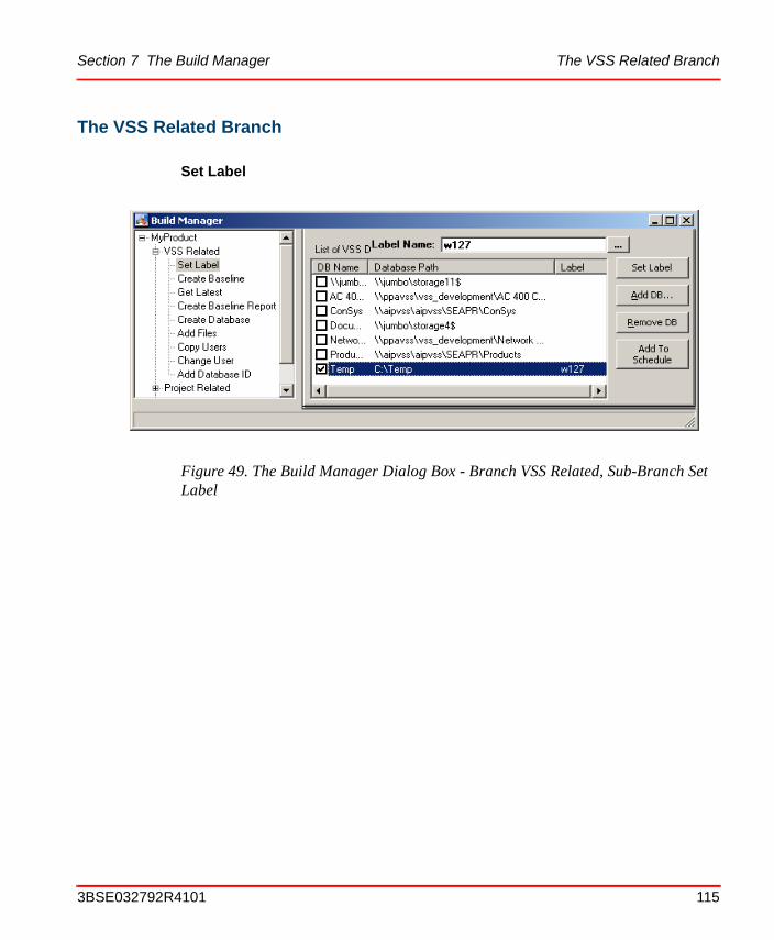
Section 7 The Build Manager The VSS Related Branch
The VSS Related Branch
Set Label
Figure 49. The Build Manager Dialog Box - Branch VSS Related, Sub-Branch Set Label
3BSE032792R4101 115
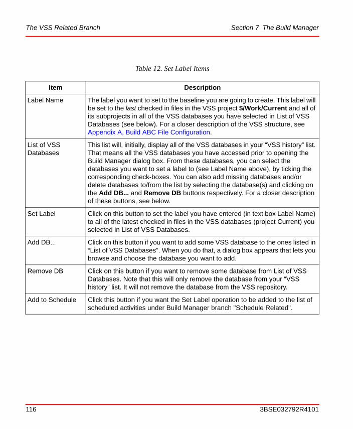
The VSS Related Branch Section 7 The Build Manager
Table 12. Set Label Items
Item Description
Label Name The label you want to set to the baseline you are going to create. This label will be set to the last checked in files in the VSS project $/Work/Current and all of its subprojects in all of the VSS databases you have selected in List of VSS Databases (see below). For a closer description of the VSS structure, see Appendix A, Build ABC File Configuration.
List of VSS Databases
This list will, initially, display all of the VSS databases in your “VSS history” list. That means all the VSS databases you have accessed prior to opening the Build Manager dialog box. From these databases, you can select the databases you want to set a label to (see Label Name above), by ticking the corresponding check-boxes. You can also add missing databases and/or delete databases to/from the list by selecting the database(s) and clicking on the Add DB... and Remove DB buttons respectively. For a closer description of these buttons, see below.
Set Label Click on this button to set the label you have entered (in text box Label Name) to all of the latest checked in files in the VSS databases (project Current) you selected in List of VSS Databases.
Add DB... Click on this button if you want to add some VSS database to the ones listed in “List of VSS Databases”. When you do that, a dialog box appears that lets you browse and choose the database you want to add.
Remove DB Click on this button if you want to remove some database from List of VSS Databases. Note that this will only remove the database from your “VSS history” list. It will not remove the database from the VSS repository.
Add to Schedule Click this button if you want the Set Label operation to be added to the list of scheduled activities under Build Manager branch "Schedule Related".
116 3BSE032792R4101
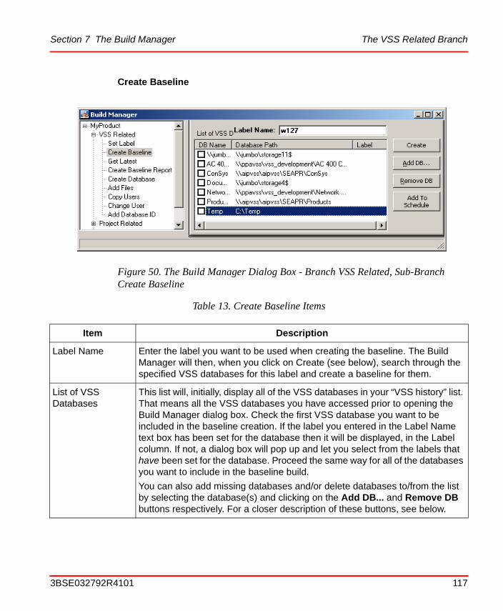
Section 7 The Build Manager The VSS Related Branch
Create Baseline
Figure 50. The Build Manager Dialog Box - Branch VSS Related, Sub-Branch Create Baseline
Table 13. Create Baseline Items
Item Description
Label Name Enter the label you want to be used when creating the baseline. The Build Manager will then, when you click on Create (see below), search through the specified VSS databases for this label and create a baseline for them.
List of VSS Databases
This list will, initially, display all of the VSS databases in your “VSS history” list. That means all the VSS databases you have accessed prior to opening the Build Manager dialog box. Check the first VSS database you want to be included in the baseline creation. If the label you entered in the Label Name text box has been set for the database then it will be displayed, in the Label column. If not, a dialog box will pop up and let you select from the labels that have been set for the database. Proceed the same way for all of the databases you want to include in the baseline build.
You can also add missing databases and/or delete databases to/from the list by selecting the database(s) and clicking on the Add DB... and Remove DB buttons respectively. For a closer description of these buttons, see below.
3BSE032792R4101 117
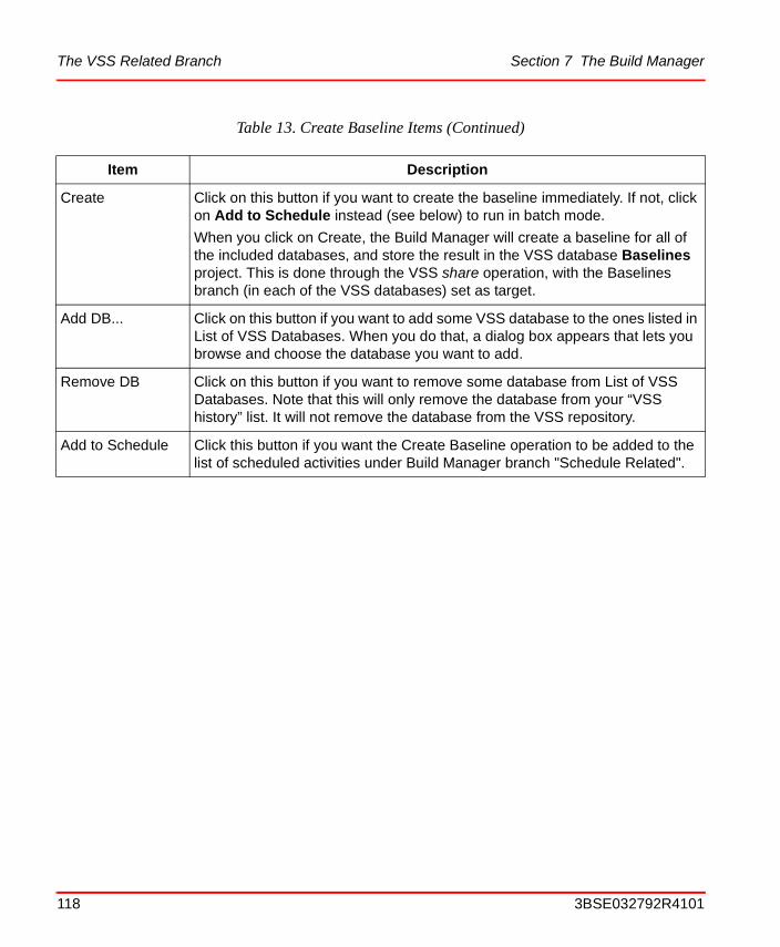
The VSS Related Branch Section 7 The Build Manager
Create Click on this button if you want to create the baseline immediately. If not, click on Add to Schedule instead (see below) to run in batch mode.
When you click on Create, the Build Manager will create a baseline for all of the included databases, and store the result in the VSS database Baselines project. This is done through the VSS share operation, with the Baselines branch (in each of the VSS databases) set as target.
Add DB... Click on this button if you want to add some VSS database to the ones listed in List of VSS Databases. When you do that, a dialog box appears that lets you browse and choose the database you want to add.
Remove DB Click on this button if you want to remove some database from List of VSS Databases. Note that this will only remove the database from your “VSS history” list. It will not remove the database from the VSS repository.
Add to Schedule Click this button if you want the Create Baseline operation to be added to the list of scheduled activities under Build Manager branch "Schedule Related".
Table 13. Create Baseline Items (Continued)
Item Description
118 3BSE032792R4101
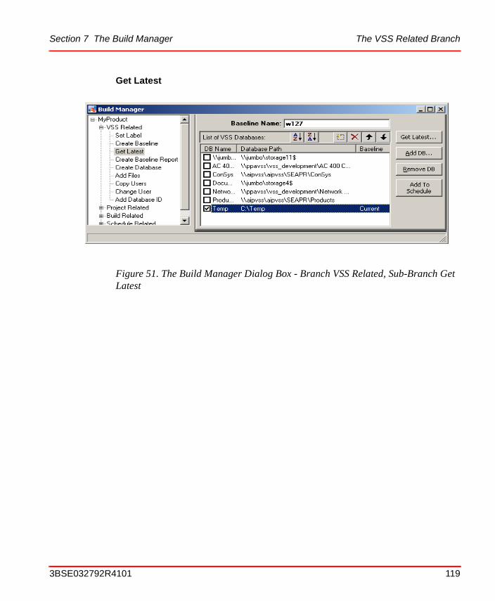
Section 7 The Build Manager The VSS Related Branch
Get Latest
Figure 51. The Build Manager Dialog Box - Branch VSS Related, Sub-Branch Get Latest
3BSE032792R4101 119
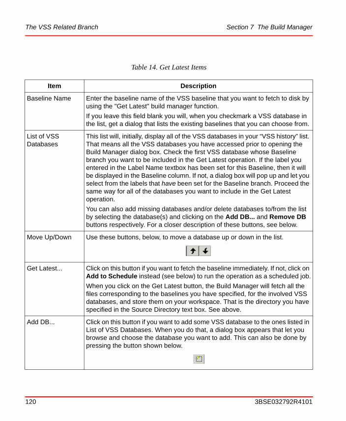
The VSS Related Branch Section 7 The Build Manager
Table 14. Get Latest Items
Item Description
Baseline Name Enter the baseline name of the VSS baseline that you want to fetch to disk by using the "Get Latest" build manager function.
If you leave this field blank you will, when you checkmark a VSS database in the list, get a dialog that lists the existing baselines that you can choose from.
List of VSS Databases
This list will, initially, display all of the VSS databases in your “VSS history” list. That means all the VSS databases you have accessed prior to opening the Build Manager dialog box. Check the first VSS database whose Baseline branch you want to be included in the Get Latest operation. If the label you entered in the Label Name textbox has been set for this Baseline, then it will be displayed in the Baseline column. If not, a dialog box will pop up and let you select from the labels that have been set for the Baseline branch. Proceed the same way for all of the databases you want to include in the Get Latest operation.
You can also add missing databases and/or delete databases to/from the list by selecting the database(s) and clicking on the Add DB... and Remove DB buttons respectively. For a closer description of these buttons, see below.
Move Up/Down Use these buttons, below, to move a database up or down in the list.
Get Latest... Click on this button if you want to fetch the baseline immediately. If not, click on Add to Schedule instead (see below) to run the operation as a scheduled job.
When you click on the Get Latest button, the Build Manager will fetch all the files corresponding to the baselines you have specified, for the involved VSS databases, and store them on your workspace. That is the directory you have specified in the Source Directory text box. See above.
Add DB... Click on this button if you want to add some VSS database to the ones listed in List of VSS Databases. When you do that, a dialog box appears that let you browse and choose the database you want to add. This can also be done by pressing the button shown below.
120 3BSE032792R4101
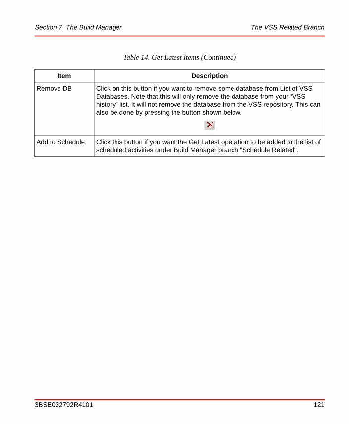
Section 7 The Build Manager The VSS Related Branch
Remove DB Click on this button if you want to remove some database from List of VSS Databases. Note that this will only remove the database from your “VSS history” list. It will not remove the database from the VSS repository. This can also be done by pressing the button shown below.
Add to Schedule Click this button if you want the Get Latest operation to be added to the list of scheduled activities under Build Manager branch "Schedule Related".
Table 14. Get Latest Items (Continued)
Item Description
3BSE032792R4101 121

The VSS Related Branch Section 7 The Build Manager
Create Baseline Report
Figure 52. The Build Manager dialog box - Branch VSS Related, Sub-Branch Create Baseline Report
Table 15. Create Baseline Report Items
Item Description
Output Path and File Name This is where you specify the destination directory and file name on the report that will be created.
The default file type is .csv since the created report is a semicolon separated list. This is a format that is readable in a simple text editor such as Microsoft Notepad and can also be opened in Microsoft Excel.
Create When you click on this button you will start the baseline report creation. When the report creation is done you will get a message.
122 3BSE032792R4101
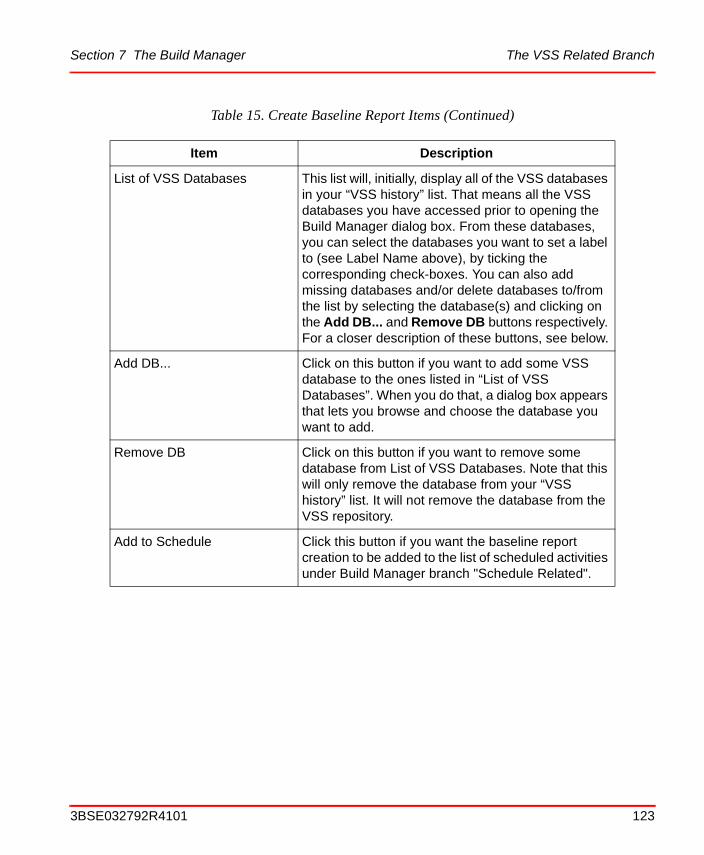
Section 7 The Build Manager The VSS Related Branch
List of VSS Databases This list will, initially, display all of the VSS databases in your “VSS history” list. That means all the VSS databases you have accessed prior to opening the Build Manager dialog box. From these databases, you can select the databases you want to set a label to (see Label Name above), by ticking the corresponding check-boxes. You can also add missing databases and/or delete databases to/from the list by selecting the database(s) and clicking on the Add DB... and Remove DB buttons respectively. For a closer description of these buttons, see below.
Add DB... Click on this button if you want to add some VSS database to the ones listed in “List of VSS Databases”. When you do that, a dialog box appears that lets you browse and choose the database you want to add.
Remove DB Click on this button if you want to remove some database from List of VSS Databases. Note that this will only remove the database from your “VSS history” list. It will not remove the database from the VSS repository.
Add to Schedule Click this button if you want the baseline report creation to be added to the list of scheduled activities under Build Manager branch "Schedule Related".
Table 15. Create Baseline Report Items (Continued)
Item Description
3BSE032792R4101 123
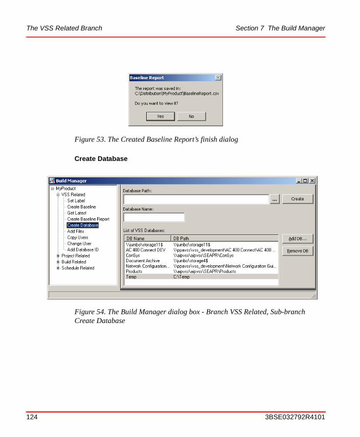
The VSS Related Branch Section 7 The Build Manager
Create Database
Figure 53. The Created Baseline Report’s finish dialog
Figure 54. The Build Manager dialog box - Branch VSS Related, Sub-branch Create Database
124 3BSE032792R4101
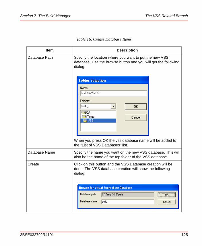
Section 7 The Build Manager The VSS Related Branch
Table 16. Create Database Items
Item Description
Database Path Specify the location where you want to put the new VSS database. Use the browse button and you will get the following dialog:
When you press OK the vss database name will be added to the "List of VSS Databases" list.
Database Name Specify the name you want on the new VSS database. This will also be the name of the top folder of the VSS database.
Create Click on this button and the VSS Database creation will be done. The VSS database creation will show the following dialog:
3BSE032792R4101 125
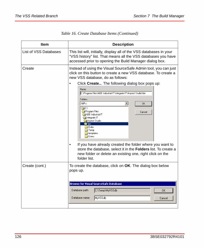
The VSS Related Branch Section 7 The Build Manager
List of VSS Databases This list will, initially, display all of the VSS databases in your “VSS history” list. That means all the VSS databases you have accessed prior to opening the Build Manager dialog box.
Create Instead of using the Visual SourceSafe Admin tool, you can just click on this button to create a new VSS database. To create a new VSS database, do as follows:
• Click Create... The following dialog box pops up:
• If you have already created the folder where you want to store the database, select it in the Folders list. To create a new folder or delete an existing one, right click on the folder list.
Create (cont.) To create the database, click on OK. The dialog box below pops up.
Table 16. Create Database Items (Continued)
Item Description
126 3BSE032792R4101
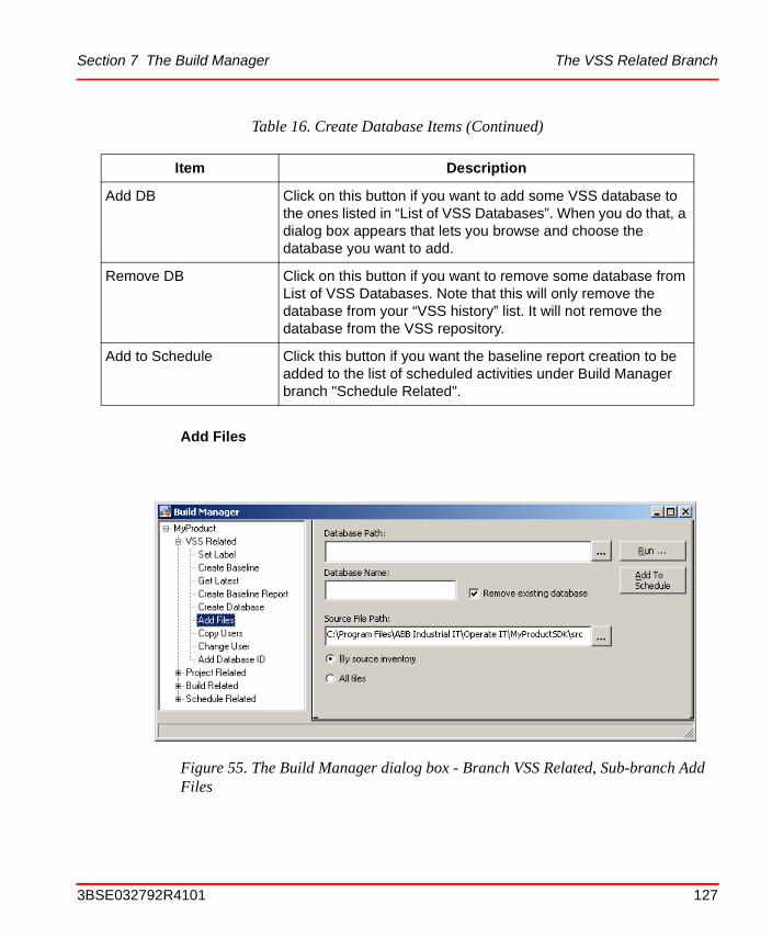
Section 7 The Build Manager The VSS Related Branch
Add Files
Add DB Click on this button if you want to add some VSS database to the ones listed in “List of VSS Databases”. When you do that, a dialog box appears that lets you browse and choose the database you want to add.
Remove DB Click on this button if you want to remove some database from List of VSS Databases. Note that this will only remove the database from your “VSS history” list. It will not remove the database from the VSS repository.
Add to Schedule Click this button if you want the baseline report creation to be added to the list of scheduled activities under Build Manager branch "Schedule Related".
Figure 55. The Build Manager dialog box - Branch VSS Related, Sub-branch Add Files
Table 16. Create Database Items (Continued)
Item Description
3BSE032792R4101 127
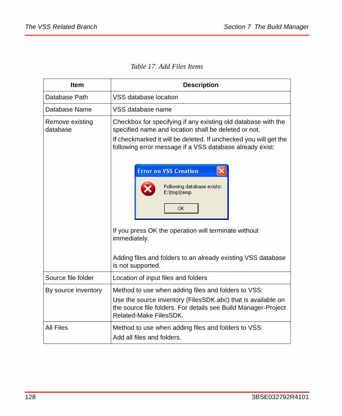
The VSS Related Branch Section 7 The Build Manager
Table 17. Add Files Items
Item Description
Database Path VSS database location
Database Name VSS database name
Remove existing database
Checkbox for specifying if any existing old database with the specified name and location shall be deleted or not.
If checkmarked it will be deleted. If unchecked you will get the following error message if a VSS database already exist:
If you press OK the operation will terminate without immediately.
Adding files and folders to an already existing VSS database is not supported.
Source file folder Location of input files and folders
By source inventory Method to use when adding files and folders to VSS:
Use the source inventory (FilesSDK.abc) that is available on the source file folders. For details see Build Manager-Project Related-Make FilesSDK.
All Files Method to use when adding files and folders to VSS:
Add all files and folders.
128 3BSE032792R4101
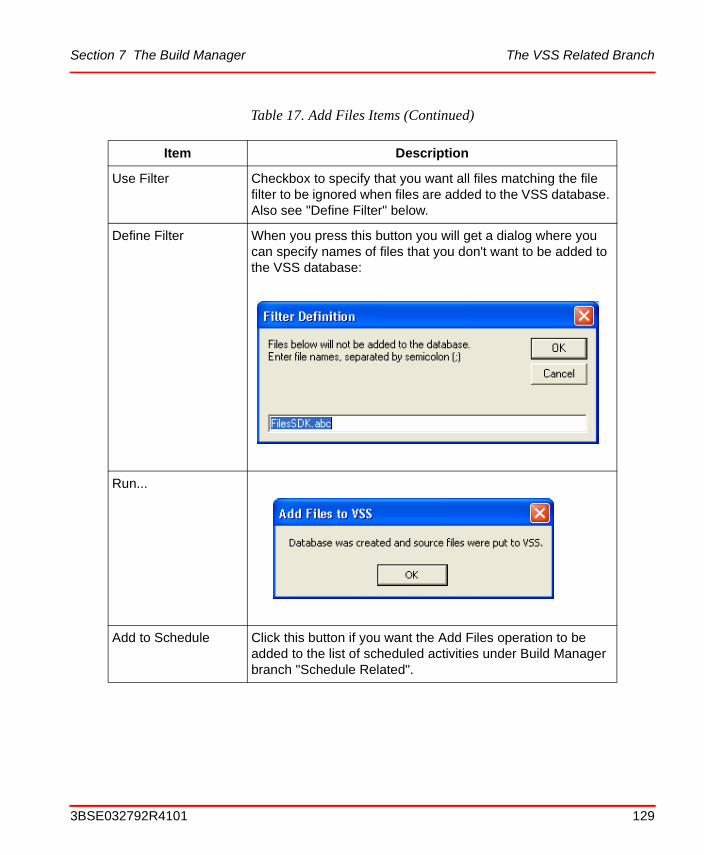
Section 7 The Build Manager The VSS Related Branch
Use Filter Checkbox to specify that you want all files matching the file filter to be ignored when files are added to the VSS database. Also see "Define Filter" below.
Define Filter When you press this button you will get a dialog where you can specify names of files that you don't want to be added to the VSS database:
Run...
Add to Schedule Click this button if you want the Add Files operation to be added to the list of scheduled activities under Build Manager branch "Schedule Related".
Table 17. Add Files Items (Continued)
Item Description
3BSE032792R4101 129
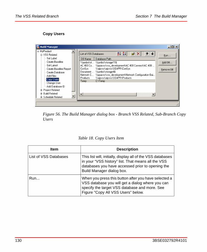
The VSS Related Branch Section 7 The Build Manager
Copy Users
Figure 56. The Build Manager dialog box - Branch VSS Related, Sub-Branch Copy Users
Table 18. Copy Users Item
Item Description
List of VSS Databases This list will, initially, display all of the VSS databases in your “VSS history” list. That means all the VSS databases you have accessed prior to opening the Build Manager dialog box.
Run... When you press this button after you have selected a VSS database you will get a dialog where you can specify the target VSS database and more. See Figure "Copy All VSS Users" below.
130 3BSE032792R4101
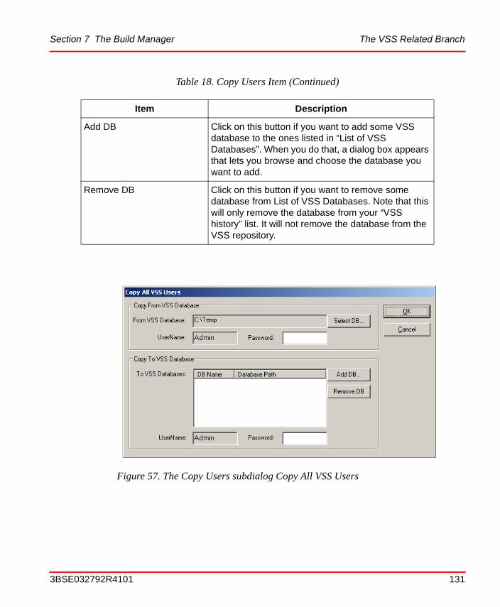
Section 7 The Build Manager The VSS Related Branch
Add DB Click on this button if you want to add some VSS database to the ones listed in “List of VSS Databases”. When you do that, a dialog box appears that lets you browse and choose the database you want to add.
Remove DB Click on this button if you want to remove some database from List of VSS Databases. Note that this will only remove the database from your “VSS history” list. It will not remove the database from the VSS repository.
Figure 57. The Copy Users subdialog Copy All VSS Users
Table 18. Copy Users Item (Continued)
Item Description
3BSE032792R4101 131
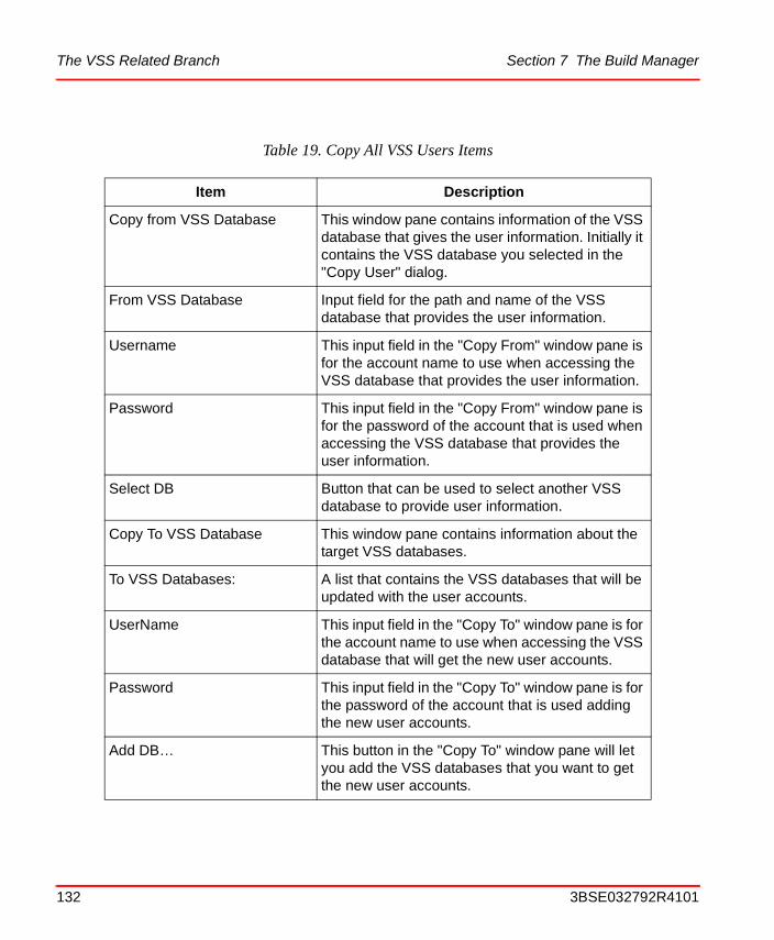
The VSS Related Branch Section 7 The Build Manager
Table 19. Copy All VSS Users Items
Item Description
Copy from VSS Database This window pane contains information of the VSS database that gives the user information. Initially it contains the VSS database you selected in the "Copy User" dialog.
From VSS Database Input field for the path and name of the VSS database that provides the user information.
Username This input field in the "Copy From" window pane is for the account name to use when accessing the VSS database that provides the user information.
Password This input field in the "Copy From" window pane is for the password of the account that is used when accessing the VSS database that provides the user information.
Select DB Button that can be used to select another VSS database to provide user information.
Copy To VSS Database This window pane contains information about the target VSS databases.
To VSS Databases: A list that contains the VSS databases that will be updated with the user accounts.
UserName This input field in the "Copy To" window pane is for the account name to use when accessing the VSS database that will get the new user accounts.
Password This input field in the "Copy To" window pane is for the password of the account that is used adding the new user accounts.
Add DB… This button in the "Copy To" window pane will let you add the VSS databases that you want to get the new user accounts.
132 3BSE032792R4101
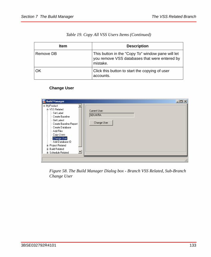
Section 7 The Build Manager The VSS Related Branch
Change User
Remove DB This button in the "Copy To" window pane will let you remove VSS databases that were entered by mistake.
OK Click this button to start the copying of user accounts.
Figure 58. The Build Manager Dialog box - Branch VSS Related, Sub-Branch Change User
Table 19. Copy All VSS Users Items (Continued)
Item Description
3BSE032792R4101 133

The VSS Related Branch Section 7 The Build Manager
Table 20. Change User Item
Item Description
Current User This field contains the VSS user name that is currently used by the Build Manager when performing VSS operations. The default user is the user name of the user currently logged in to Windows.
Change User When you press this button you will get a dialog where you can specify the VSS user name and password that you want the build manager to use when accessing VSS databases:
134 3BSE032792R4101
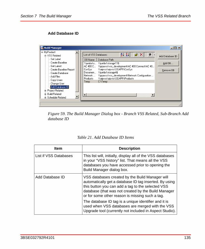
Section 7 The Build Manager The VSS Related Branch
Add Database ID
Figure 59. The Build Manager Dialog box - Branch VSS Related, Sub-Branch Add database ID
Table 21. Add Database ID Items
Item Description
List if VSS Databases This list will, initially, display all of the VSS databases in your “VSS history” list. That means all the VSS databases you have accessed prior to opening the Build Manager dialog box.
Add Database ID VSS databases created by the Build Manager will automatically get a database ID tag inserted. By using this button you can add a tag to the selected VSS database (that was not created by the Build Manager or for some other reason is missing such a tag.
The database ID tag is a unique identifier and it is used when VSS databases are merged with the VSS Upgrade tool (currently not included in Aspect Studio).
3BSE032792R4101 135
The Project Related Branch Section 7 The Build Manager
The Project Related Branch
The “Project Related” operations of the Build Manager perform tasks that are necessary for a successful execution of the Visual Studio autobuild.
Add DB... Click on this button if you want to add some VSS database to the ones listed in “List of VSS Databases”. When you do that, a dialog box appears that lets you browse and choose the database you want to add.
Remove DB Click on this button if you want to remove some database from List of VSS Databases. Note that this will only remove the database from your “VSS history” list. It will not remove the database from the VSS repository.
Table 21. Add Database ID Items (Continued)
Item Description
136 3BSE032792R4101
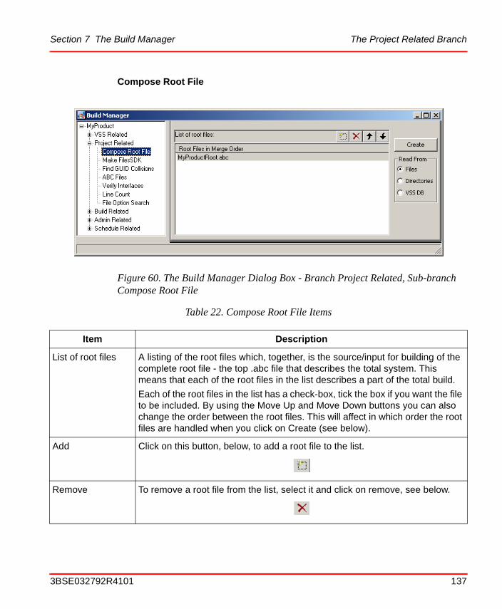
Section 7 The Build Manager The Project Related Branch
Compose Root File
Figure 60. The Build Manager Dialog Box - Branch Project Related, Sub-branch Compose Root File
Table 22. Compose Root File Items
Item Description
List of root files A listing of the root files which, together, is the source/input for building of the complete root file - the top .abc file that describes the total system. This means that each of the root files in the list describes a part of the total build.
Each of the root files in the list has a check-box, tick the box if you want the file to be included. By using the Move Up and Move Down buttons you can also change the order between the root files. This will affect in which order the root files are handled when you click on Create (see below).
Add Click on this button, below, to add a root file to the list.
Remove To remove a root file from the list, select it and click on remove, see below.
3BSE032792R4101 137
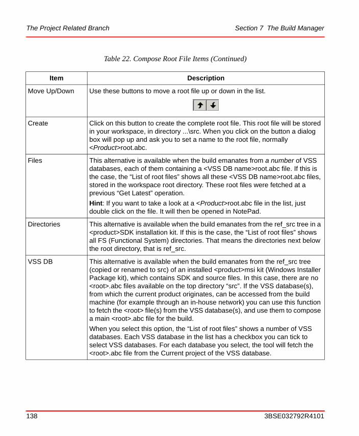
The Project Related Branch Section 7 The Build Manager
Move Up/Down Use these buttons to move a root file up or down in the list.
Create Click on this button to create the complete root file. This root file will be stored in your workspace, in directory ...\src. When you click on the button a dialog box will pop up and ask you to set a name to the root file, normally <Product>root.abc.
Files This alternative is available when the build emanates from a number of VSS databases, each of them containing a <VSS DB name>root.abc file. If this is the case, the “List of root files” shows all these <VSS DB name>root.abc files, stored in the workspace root directory. These root files were fetched at a previous “Get Latest” operation.
Hint: If you want to take a look at a <Product>root.abc file in the list, just double click on the file. It will then be opened in NotePad.
Directories This alternative is available when the build emanates from the ref_src tree in a <product>SDK installation kit. If this is the case, the “List of root files” shows all FS (Functional System) directories. That means the directories next below the root directory, that is ref_src.
VSS DB This alternative is available when the build emanates from the ref_src tree (copied or renamed to src) of an installed <product>msi kit (Windows Installer Package kit), which contains SDK and source files. In this case, there are no <root>.abc files available on the top directory “src”. If the VSS database(s), from which the current product originates, can be accessed from the build machine (for example through an in-house network) you can use this function to fetch the <root> file(s) from the VSS database(s), and use them to compose a main <root>.abc file for the build.
When you select this option, the “List of root files” shows a number of VSS databases. Each VSS database in the list has a checkbox you can tick to select VSS databases. For each database you select, the tool will fetch the <root>.abc file from the Current project of the VSS database.
Table 22. Compose Root File Items (Continued)
Item Description
138 3BSE032792R4101
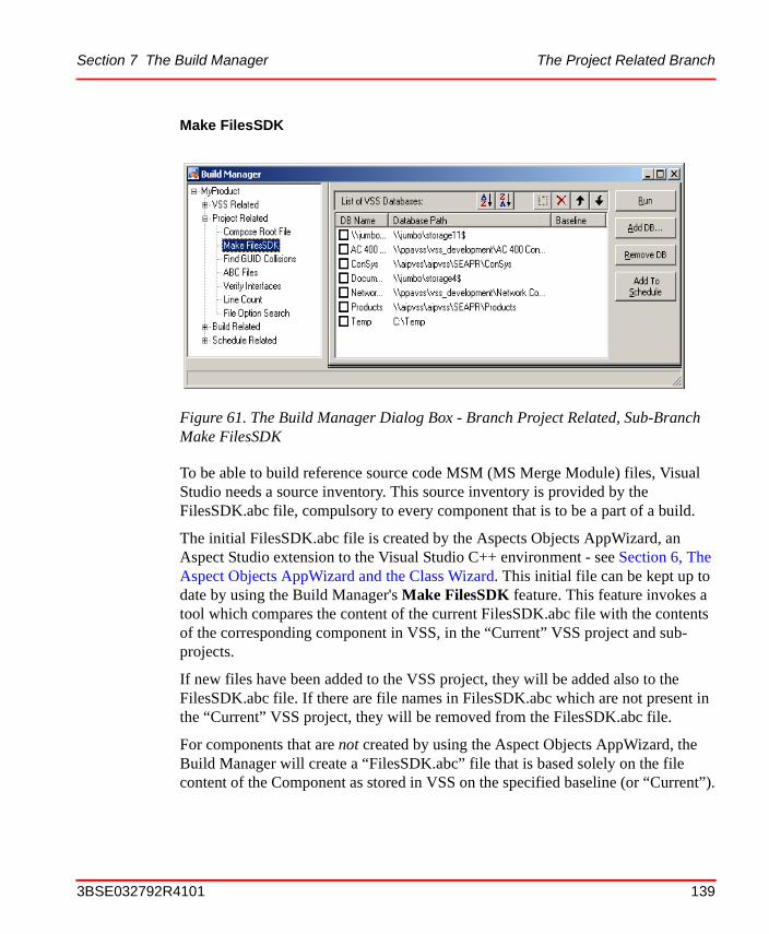
Section 7 The Build Manager The Project Related Branch
Make FilesSDK
To be able to build reference source code MSM (MS Merge Module) files, Visual Studio needs a source inventory. This source inventory is provided by the FilesSDK.abc file, compulsory to every component that is to be a part of a build.
The initial FilesSDK.abc file is created by the Aspects Objects AppWizard, an Aspect Studio extension to the Visual Studio C++ environment - see Section 6, The Aspect Objects AppWizard and the Class Wizard. This initial file can be kept up to date by using the Build Manager's Make FilesSDK feature. This feature invokes a tool which compares the content of the current FilesSDK.abc file with the contents of the corresponding component in VSS, in the “Current” VSS project and sub-projects.
If new files have been added to the VSS project, they will be added also to the FilesSDK.abc file. If there are file names in FilesSDK.abc which are not present in the “Current” VSS project, they will be removed from the FilesSDK.abc file.
For components that are not created by using the Aspect Objects AppWizard, the Build Manager will create a “FilesSDK.abc” file that is based solely on the file content of the Component as stored in VSS on the specified baseline (or “Current”).
Figure 61. The Build Manager Dialog Box - Branch Project Related, Sub-Branch Make FilesSDK
3BSE032792R4101 139

The Project Related Branch Section 7 The Build Manager
Table 23. Make FilesSDK Items
Item Description
List of VSS Databases
This list will, initially, display all of the VSS databases in your “VSS history” list. That means all the VSS databases you have accessed prior to opening the Build Manager dialog box. When you tick the checkbox corresponding to one of the VSS databases in the list, then some initial checks will be carried out:
• Is there a <VSS DB>root.abc file stored on the workspace root?
• Is the content of the selected VSS database - that is what has been fetched at the Get Latest operation -available in the workspace?
If the answer to both of the questions is “yes”, then you are allowed to tick the checkbox (the tick mark will remain). If not, you will get a message telling you that the requirements for an update of the FilesSDK.abc file are not met.
Run Click on this button to update the FilesSDK.abc file. After completing the update, a log file will shown.
Add DB... Add a VSS database to List of VSS databases. This can also be done by pressing the button shown below.
Remove DB Remove a VSS database from List of VSS databases. This can also be done by pressing the button shown below.
Move Up/Down Use these buttons to move a database up or down in the list.
Add to Schedule Click this button if you want the Make FilesSDK operation to be added to the list of scheduled activities under Build Manager branch “Schedule Related”.
140 3BSE032792R4101
Section 7 The Build Manager The Project Related Branch
Find GUID Collisions
The Product Packager, another tool included in the Aspect Studio and described later in this guide, assembles components into MSI (MS Installer) product kits. Each of the components in a product must be assigned a unique identifier which is used to identify the components when the product is installed, uninstalled, and when a Service Pack for the product is installed. A component’s GUID is specified in the component’s build.abc file. Example (extract from a component build.abc file):
GUID: 3253CB25-D6F9-11d2-A15B-00104BAF7099
Sometimes a new component is initially created by copying and modifying the source code of an existing component, thus creating a new, empty component. When a new component is created this way, it might happen that the programmer forgets to create a new GUID in the new component’s build.abc file. If that happens, there will be two components with different functionality, but having the same GUID value.
To detect such collisions within a project with, maybe, hundreds of components is a tedious and cumbersome work. To help the developers carry out this work, the Build Manager provides a tool to find and present such collisions - the Find GUID Collisions tool.
Figure 62. The Build Manager Dialog Box - Branch Project Related, Sub-Branch Find GUID Collisions
3BSE032792R4101 141

The Project Related Branch Section 7 The Build Manager
When you activate this tool, it will present a dialog box in which you can specify a <root>.abc file. The tool will then search through the build structure defined by the <root>.abc file - from top to bottom - in order to find and check all component build.abc files. All the GUIDs that are found will be checked for duplicates. When a duplicate is found, you will get an error message with information about path and filename to the files that contain the duplicated GUID.
This test is also automatically done by the Product Packager before build of a distribution.
Table 24. Find GUID Collisions Items
Item Description
Choose Root Files to use for the search
Tick the root .abc files you want to be used as the top files in the search for collisions. The Find GUID Collisions tool will then, based on the root .abc file, find the included FSs, then the SMs, and finally the Components.
Hint: If you want to take a look at a <Product>root.abc file in the list, just double click on the file. It will then be opened in NotePad.
List of Files with GUID Collisions
The search result. A closer description of the result is presented in the log file created during the search.
Find Collisions Click on this button to start the search for collisions.
Save to File Click on this button if you want to save the search result in a log file.
142 3BSE032792R4101

Section 7 The Build Manager The Project Related Branch
ABC Files
The source code directory tree of an Aspect Studio compliant product contains typically a number of Functional Subsystems (FS), each with a number of System Modules (SM), each containing a number of components. To build the complete structure with “Autobuild” add-in of Visual Studio requires that each level of the structure describes what comes beneath. This description is done in files called “build.abc”.
Figure 63. The Build Manager Dialog Box - Branch Project Related, Sub-Branch ABC Files
3BSE032792R4101 143
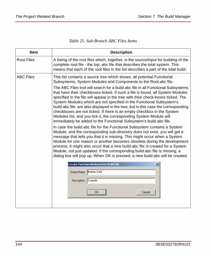
The Project Related Branch Section 7 The Build Manager
Table 25. Sub-Branch ABC Files Items
Item Description
Root Files A listing of the root files which, together, is the source/input for building of the complete root file - the top .abc file that describes the total system. This means that each of the root files in the list describes a part of the total build.
ABC Files This list contains a source tree which shows, all potential Functional Subsystems, System Modules and Components to the Root.abc file.
The ABC Files tool will search for a build.abc file in all Functional Subsystems that have their checkboxes ticked. If such a file is found, all System Modules specified in the file will appear in the tree with their check-boxes ticked. The System Modules which are not specified in the Functional Subsystem’s build.abc file, are also displayed in the tree, but in this case the corresponding checkboxes are not ticked. If there is an empty checkbox in the System Modules list, and you tick it, the corresponding System Module will immediately be added to the Functional Subsystem’s build.abc file.
In case the build.abc file for the Functional Subsystem contains a System Module, and the corresponding sub-directory does not exist, you will get a message that tells you that it is missing. This might occur when a System Module for one reason or another becomes obsolete during the development process. It might also occur that a new build.abc file is created for a System Module, not just updated. If the corresponding build.abc file is missing, a dialog box will pop up. When OK is pressed, a new build.abc will be created.
144 3BSE032792R4101
Section 7 The Build Manager The Project Related Branch
ABC Files (cont.)
The handling of the System Modules and Components is analogous to the handling of the Functional Subsystems list.
Hint: If you want to take a look at a System Module’s updated build.abc file, just double click on that System Module in the list.
Hint: To open the Component’s Build File Definition, just double click on the Component in the list (please see The Component Build File Definition on page 147 for more information).
For more details, see also Appendix A, Build ABC File Configuration.
View If View is checked, no changes can be made to the structure.
Edit If Edit is checked, you can check/uncheck and move items in the ABC Files list. The build.abc files will be updated.
Table 25. Sub-Branch ABC Files Items (Continued)
Item Description
3BSE032792R4101 145
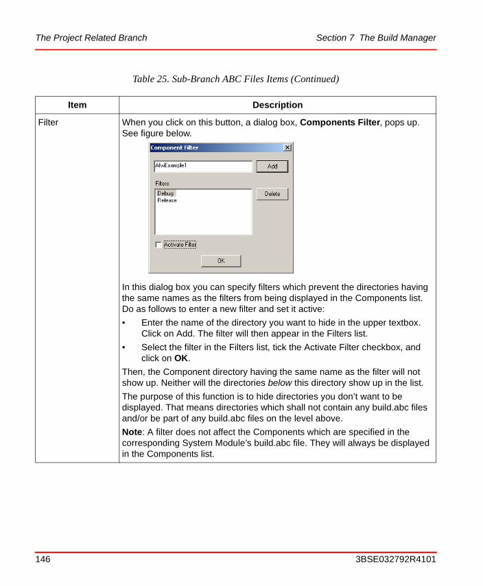
The Project Related Branch Section 7 The Build Manager
Filter When you click on this button, a dialog box, Components Filter, pops up. See figure below.
In this dialog box you can specify filters which prevent the directories having the same names as the filters from being displayed in the Components list. Do as follows to enter a new filter and set it active:
• Enter the name of the directory you want to hide in the upper textbox. Click on Add. The filter will then appear in the Filters list.
• Select the filter in the Filters list, tick the Activate Filter checkbox, and click on OK.
Then, the Component directory having the same name as the filter will not show up. Neither will the directories below this directory show up in the list.
The purpose of this function is to hide directories you don’t want to be displayed. That means directories which shall not contain any build.abc files and/or be part of any build.abc files on the level above.
Note: A filter does not affect the Components which are specified in the corresponding System Module’s build.abc file. They will always be displayed in the Components list.
Table 25. Sub-Branch ABC Files Items (Continued)
Item Description
146 3BSE032792R4101
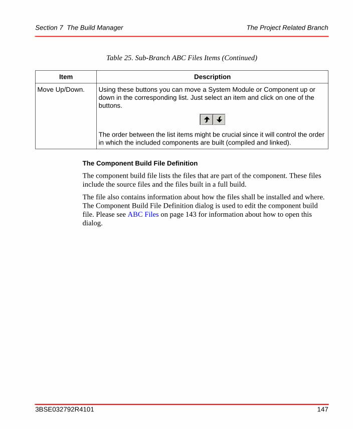
Section 7 The Build Manager The Project Related Branch
The Component Build File Definition
The component build file lists the files that are part of the component. These files include the source files and the files built in a full build.
The file also contains information about how the files shall be installed and where. The Component Build File Definition dialog is used to edit the component build file. Please see ABC Files on page 143 for information about how to open this dialog.
Move Up/Down. Using these buttons you can move a System Module or Component up or down in the corresponding list. Just select an item and click on one of the buttons.
The order between the list items might be crucial since it will control the order in which the included components are built (compiled and linked).
Table 25. Sub-Branch ABC Files Items (Continued)
Item Description
3BSE032792R4101 147
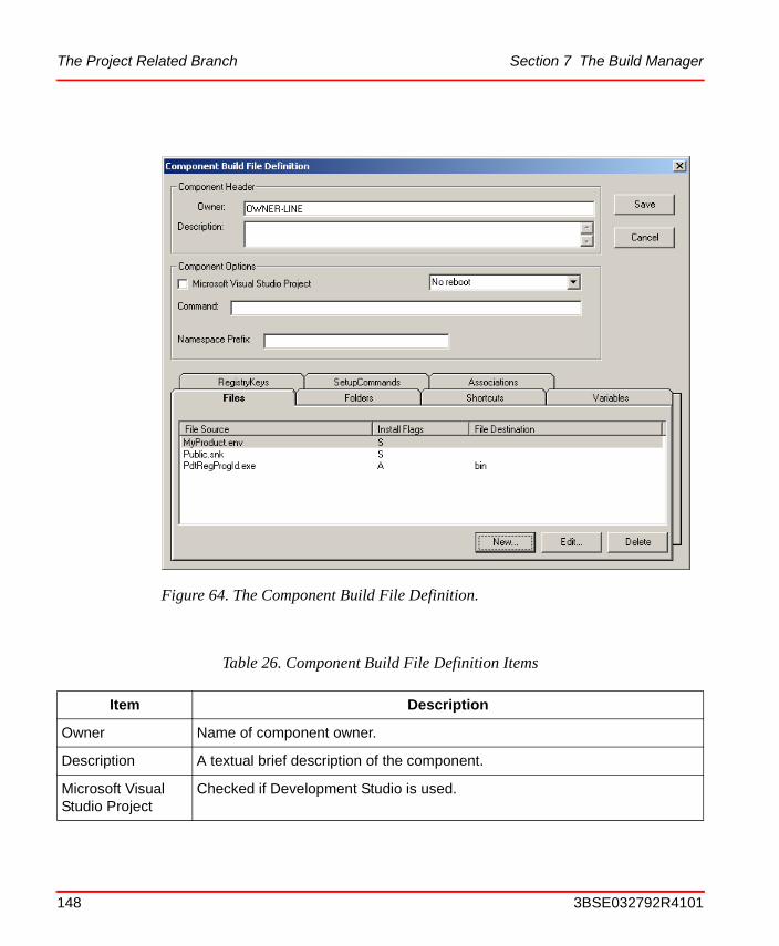
The Project Related Branch Section 7 The Build Manager
Figure 64. The Component Build File Definition.
Table 26. Component Build File Definition Items
Item Description
Owner Name of component owner.
Description A textual brief description of the component.
Microsoft Visual Studio Project
Checked if Development Studio is used.
148 3BSE032792R4101
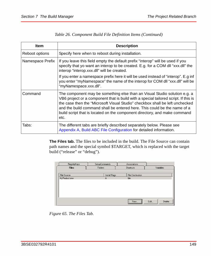
Section 7 The Build Manager The Project Related Branch
The Files tab. The files to be included in the build. The File Source can contain path names and the special symbol $TARGET, which is replaced with the target build (“release” or “debug”).
Reboot options Specify here when to reboot during installation.
Namespace Prefix If you leave this field empty the default prefix “interop” will be used if you specify that yo want an interop to be created. E.g. for a COM dll “xxx.dll” the interop “interop.xxx.dll” will be created.
If you enter a namespace prefix here it will be used instead of “interop”. E.g inf you enter “myNamespace” the name of the interop for COM dll “xxx.dll” will be “myNamespace.xxx.dll”.
Command The component may be something else than an Visual Studio solution e.g. a VB6 project or a component that is build with a special tailored script. If this is the case then the “Microsoft Visual Studio” checkbox shall be left unchecked and the build command shall be entered here. This could be the name of a build script that is located on the component directory, and make command etc.
Tabs: The different tabs are briefly described separately below. Please see Appendix A, Build ABC File Configuration for detailed information.
Figure 65. The Files Tab.
Table 26. Component Build File Definition Items (Continued)
Item Description
3BSE032792R4101 149
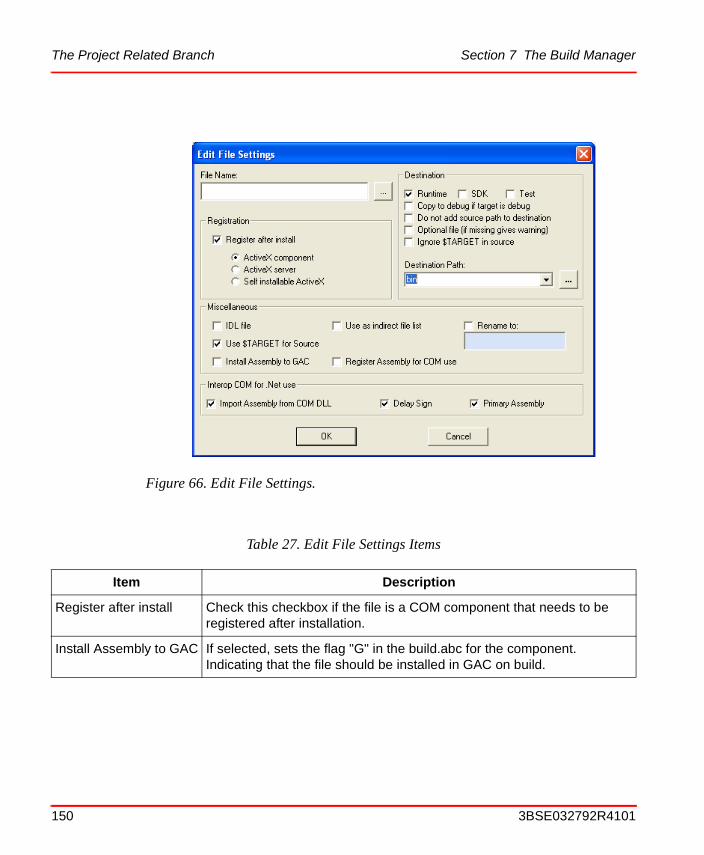
The Project Related Branch Section 7 The Build Manager
Figure 66. Edit File Settings.
Table 27. Edit File Settings Items
Item Description
Register after install Check this checkbox if the file is a COM component that needs to be registered after installation.
Install Assembly to GAC If selected, sets the flag "G" in the build.abc for the component. Indicating that the file should be installed in GAC on build.
150 3BSE032792R4101
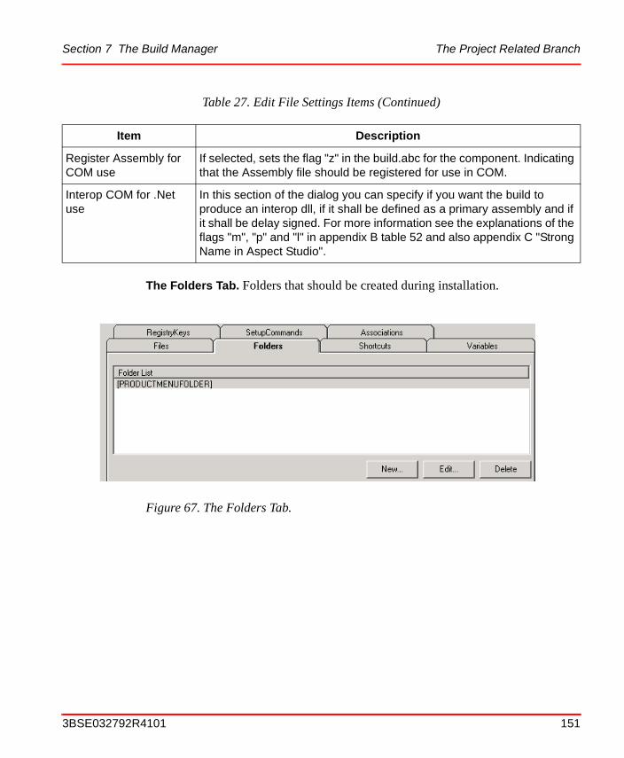
Section 7 The Build Manager The Project Related Branch
The Folders Tab. Folders that should be created during installation.
Register Assembly for COM use
If selected, sets the flag "z" in the build.abc for the component. Indicating that the Assembly file should be registered for use in COM.
Interop COM for .Net use
In this section of the dialog you can specify if you want the build to produce an interop dll, if it shall be defined as a primary assembly and if it shall be delay signed. For more information see the explanations of the flags "m", "p" and "l" in appendix B table 52 and also appendix C "Strong Name in Aspect Studio".
Figure 67. The Folders Tab.
Table 27. Edit File Settings Items (Continued)
Item Description
3BSE032792R4101 151
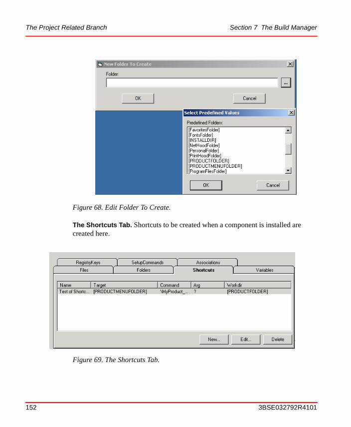
The Project Related Branch Section 7 The Build Manager
The Shortcuts Tab. Shortcuts to be created when a component is installed are created here.
Figure 68. Edit Folder To Create.
Figure 69. The Shortcuts Tab.
152 3BSE032792R4101
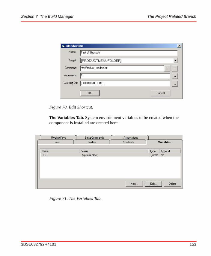
Section 7 The Build Manager The Project Related Branch
The Variables Tab. System environment variables to be created when the component is installed are created here.
Figure 70. Edit Shortcut.
Figure 71. The Variables Tab.
3BSE032792R4101 153
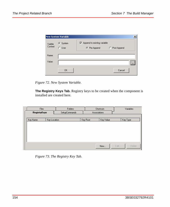
The Project Related Branch Section 7 The Build Manager
The Registry Keys Tab. Registry keys to be created when the component is installed are created here.
Figure 72. New System Variable.
Figure 73. The Registry Key Tab.
154 3BSE032792R4101
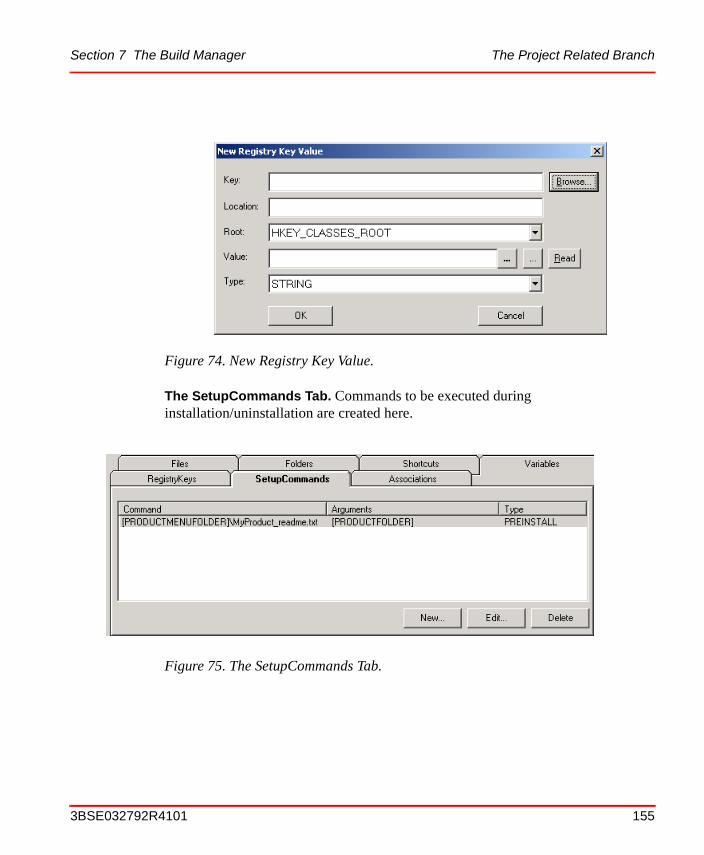
Section 7 The Build Manager The Project Related Branch
The SetupCommands Tab. Commands to be executed during installation/uninstallation are created here.
Figure 74. New Registry Key Value.
Figure 75. The SetupCommands Tab.
3BSE032792R4101 155
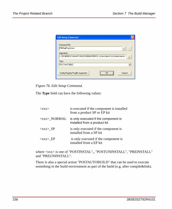
The Project Related Branch Section 7 The Build Manager
The Type field can have the following values:
where <xxx> is one of "POSTINSTAL",, "POSTUNINSTALL", "PREINSTALL" and "PREUNINSTALL".
There is also a special action "POSTAUTOBUILD" that can be used to execute something in the build environment as part of the build (e.g. after compile&link).
Figure 76. Edit Setup Command.
<xxx> is executed if the component is installed from a product SP or EP kit
<xxx>_NORMAL is only executed if the component is installed from a product kit
<xxx>_SP is only executed if the component is installed from a SP kit
<xxx>_EP is only executed if the component is installed from a EP kit
156 3BSE032792R4101

Section 7 The Build Manager The Project Related Branch
Then Config Registry ProgID Arguments is clicked, the following dialog appears, see Figure 77.
When Create New Category is selected the diagram shown in Figure 78 is displayed.
Figure 77. Config Registry ProgID Arguments Dialog
Figure 78. New Setup Command
3BSE032792R4101 157
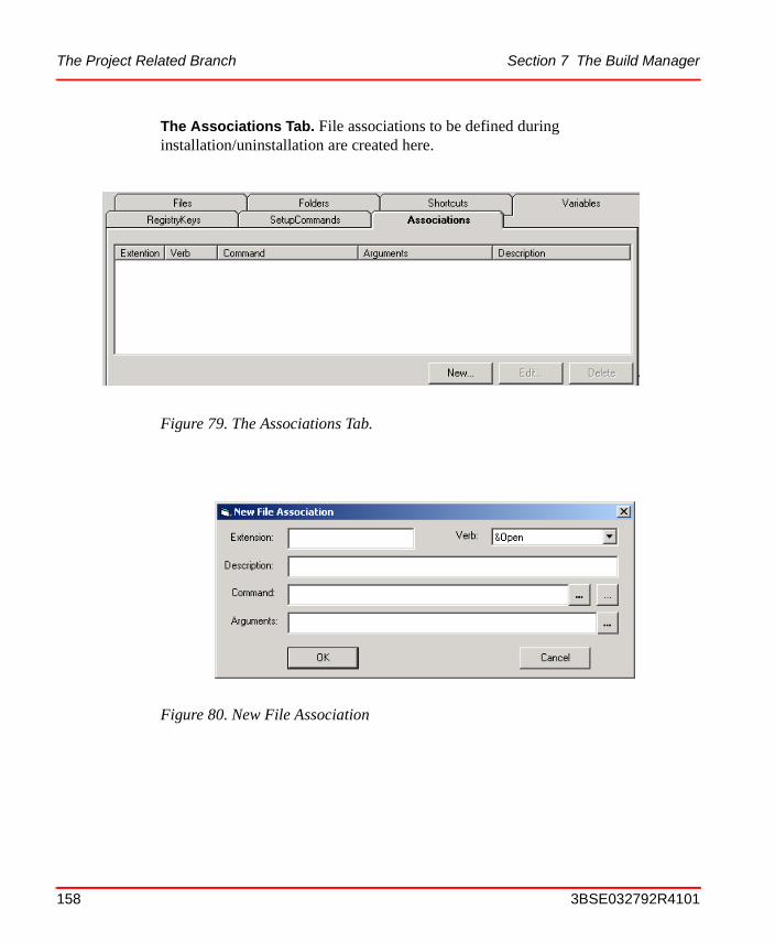
The Project Related Branch Section 7 The Build Manager
The Associations Tab. File associations to be defined during installation/uninstallation are created here.
Figure 79. The Associations Tab.
Figure 80. New File Association
158 3BSE032792R4101
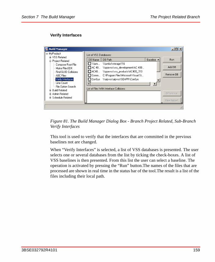
Section 7 The Build Manager The Project Related Branch
Verify Interfaces
This tool is used to verify that the interfaces that are committed in the previous baselines not are changed.
When “Verify Interfaces” is selected, a list of VSS databases is presented. The user selects one or several databases from the list by ticking the check-boxes. A list of VSS baselines is then presented. From this list the user can select a baseline. The operation is activated by pressing the “Run” button.The names of the files that are processed are shown in real time in the status bar of the tool.The result is a list of the files including their local path.
Figure 81. The Build Manager Dialog Box - Branch Project Related, Sub-Branch Verify Interfaces
3BSE032792R4101 159
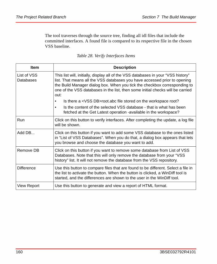
The Project Related Branch Section 7 The Build Manager
The tool traverses through the source tree, finding all idl files that include the committed interfaces. A found file is compared to its respective file in the chosen VSS baseline.
Table 28. Verify Interfaces Items
Item Description
List of VSS Databases
This list will, initially, display all of the VSS databases in your “VSS history” list. That means all the VSS databases you have accessed prior to opening the Build Manager dialog box. When you tick the checkbox corresponding to one of the VSS databases in the list, then some initial checks will be carried out:
• Is there a <VSS DB>root.abc file stored on the workspace root?
• Is the content of the selected VSS database - that is what has been fetched at the Get Latest operation -available in the workspace?
Run Click on this button to verify interfaces. After completing the update, a log file will be shown.
Add DB... Click on this button if you want to add some VSS database to the ones listed in “List of VSS Databases”. When you do that, a dialog box appears that lets you browse and choose the database you want to add.
Remove DB Click on this button if you want to remove some database from List of VSS Databases. Note that this will only remove the database from your “VSS history” list. It will not remove the database from the VSS repository.
Difference Use this button to compare files that are found to be different. Select a file in the list to activate the button. When the button is clicked, a WinDiff tool is started, and the differences are shown to the user in the WinDiff tool.
View Report Use this button to generate and view a report of HTML format.
160 3BSE032792R4101
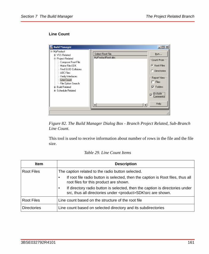
Section 7 The Build Manager The Project Related Branch
Line Count
This tool is used to receive information about number of rows in the file and the file size.
Figure 82. The Build Manager Dialog Box - Branch Project Related, Sub-Branch Line Count.
Table 29. Line Count Items
Item Description
Root Files The caption related to the radio button selected.
• If root file radio button is selected, then the caption is Root files, thus all root files for this product are shown.
• If directory radio button is selected, then the caption is directories under src, thus all directories under <product>SDK\src are shown.
Root Files Line count based on the structure of the root file
Directories Line count based on selected directory and its subdirectories
3BSE032792R4101 161
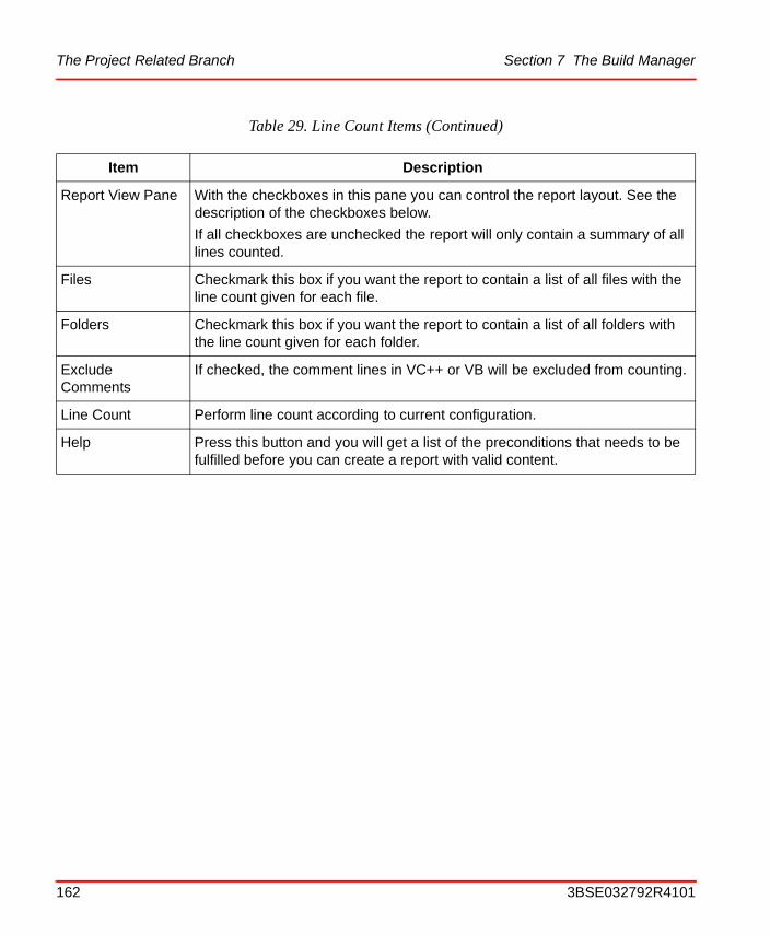
The Project Related Branch Section 7 The Build Manager
Report View Pane With the checkboxes in this pane you can control the report layout. See the description of the checkboxes below.
If all checkboxes are unchecked the report will only contain a summary of all lines counted.
Files Checkmark this box if you want the report to contain a list of all files with the line count given for each file.
Folders Checkmark this box if you want the report to contain a list of all folders with the line count given for each folder.
Exclude Comments
If checked, the comment lines in VC++ or VB will be excluded from counting.
Line Count Perform line count according to current configuration.
Help Press this button and you will get a list of the preconditions that needs to be fulfilled before you can create a report with valid content.
Table 29. Line Count Items (Continued)
Item Description
162 3BSE032792R4101

Section 7 The Build Manager The Project Related Branch
File Option Search
The term “File Options” refers to the handling options that can be set in a.abc file on the Component level. Those options describe how the files that are parts of the component shall be handled at installation of the Component.
Figure 83. The Build Manager Dialog Box - Branch Project Related, Sub-Branch File Option Search.
3BSE032792R4101 163
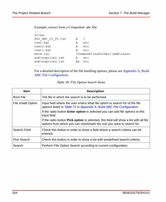
The Project Related Branch Section 7 The Build Manager
Example, extract from a Component .abc file:....Files:FS2_SM1_C1_F1.txt A ?test.bat A etctest2.bat A etctest3.bat A etcmove.txt [CommonFilesFolder]\ABB\rnxvcsub\noption1.txt A etcsub\noption2.txt An etc....
For a detailed description of the file handling options, please see Appendix A, Build ABC File Configuration.
Table 30. File Option Search Items
Item Description
Root File The file in which the search is to be performed.
File Install Option Input field where the user enters what file option to search for of the file options listed in Table 72 in Appendix A, Build ABC File Configuration.
If the radio button Enter option is selected you can add file options to this input field.
If the radio button Pick option is selected, this field will show a list with all file options from which you can checkmark the one you want to search for.
Search Field Check this button in order to show a field where a search criteria can be entered.
Pick Search Check this button in order to show a list with predefined search-criteria.
Search Perform File Option Search according to current configuration.
164 3BSE032792R4101

Section 7 The Build Manager The Build Related Branch
The Build Related Branch
Here you can specify build activities such as install (the initial template) product, setup the development environment for the product, build (compile and link) the product, create Microsoft Installer merge modules (MSM), create the product package and transfer the package to a network share. An important feature available for all these activities is that you can define that they shall be added to a schedule for later activation. By using the Build Managers "Schedule Related" functions, described in a later section of this document, you can compose scripts that you can add to the Windows scheduler to be run during night etc. The different "Build Related” dialogs are described in detail below.
Open ABC file When a search for a file option finds one or more build.abc files that contains the specified option, they will be presented in the listbox below this button. Select a file and press Open ABC file and the selected build.abc file will be opened in the notepad editor.
Goto Folder When a search for a file option finds one or more build.abc files that contains the specified option they will be presented in the listbox below this button. Select a file and press Goto Folder and the folder that contains the selected build.abc file will be opened in Windows Explorer.
Table 30. File Option Search Items (Continued)
Item Description
3BSE032792R4101 165
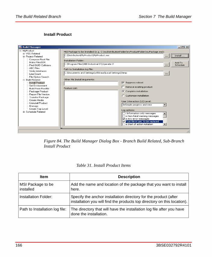
The Build Related Branch Section 7 The Build Manager
Install Product
Figure 84. The Build Manager Dialog Box - Branch Build Related, Sub-Branch Install Product
Table 31. Install Product Items
Item Description
MSI Package to be installed
Add the name and location of the package that you want to install here.
Installation Folder: Specify the anchor installation directory for the product (after installation you will find the products top directory on this location).
Path to Installation log file: The directory that will have the installation log file after you have done the installation.
166 3BSE032792R4101
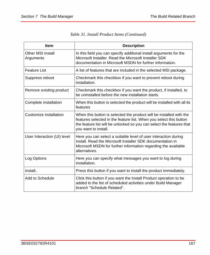
Section 7 The Build Manager The Build Related Branch
Other MSI Install Arguments
In this field you can specify additional install arguments for the Microsoft Installer. Read the Microsoft Installer SDK documentation in Microsoft MSDN for further information.
Feature List A list of features that are included in the selected MSI package.
Suppress reboot Checkmark this checkbox if you want to prevent reboot during installation.
Remove existing product Checkmark this checkbox if you want the product, if installed, to be uninstalled before the new installation starts.
Complete installation When this button is selected the product will be installed with all its features
Customize installation When this button is selected the product will be installed with the features selected in the feature list. When you select this button the feature list will be unlocked so you can select the features that you want to install.
User Interaction (UI) level Here you can select a suitable level of user interaction during install. Read the Microsoft Installer SDK documentation in Microsoft MSDN for further information regarding the available alternatives.
Log Options Here you can specify what messages you want to log during installation.
Install.. Press this button if you want to install the product immediately.
Add to Schedule Click this button if you want the Install Product operation to be added to the list of scheduled activities under Build Manager branch "Schedule Related".
Table 31. Install Product Items (Continued)
Item Description
3BSE032792R4101 167

The Build Related Branch Section 7 The Build Manager
Set Environment
Figure 85. The Build ManagerDialog Box - Branch Build Related, Sub-Branch Set Environment
Table 32. Set Environment Items
Item Description
Current Values When selected, current values of path variables and environmental variables are fetched from Visual Studio and displayed in the list box.
The contents in the listbox can be copied into the clipboard or into Notepad. This is done by right clicking on the text displayed in the list box. A context menu is then presented, see figure below.
168 3BSE032792R4101
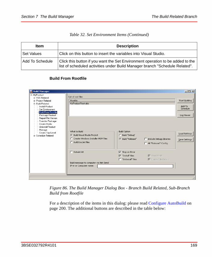
Section 7 The Build Manager The Build Related Branch
Build From Rootfile
For a description of the items in this dialog: please read Configure AutoBuild on page 200. The additional buttons are described in the table below:
Set Values Click on this button to insert the variables into Visual Studio.
Add To Schedule Click this button if you want the Set Environment operation to be added to the list of scheduled activities under Build Manager branch "Schedule Related".
Figure 86. The Build Manager Dialog Box - Branch Build Related, Sub-Branch Build from Rootfile
Table 32. Set Environment Items (Continued)
Item Description
3BSE032792R4101 169
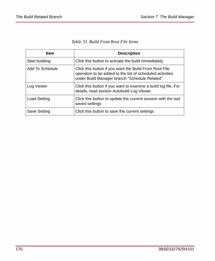
The Build Related Branch Section 7 The Build Manager
Table 33. Build From Root File Items
Item Description
Start building Click this button to activate the build immediately.
Add To Schedule Click this button if you want the Build From Root File operation to be added to the list of scheduled activities under Build Manager branch "Schedule Related".
Log Viewer Click this button if you want to examine a build log file. For details, read section Autobuild Log Viewer.
Load Setting Click this button to update the current session with the last saved settings
Save Setting Click this button to save the current settings
170 3BSE032792R4101
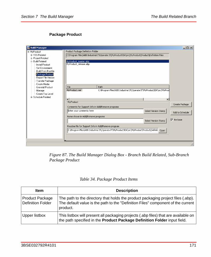
Section 7 The Build Manager The Build Related Branch
Package Product
Figure 87. The Build Manager Dialog Box - Branch Build Related, Sub-Branch Package Product
Table 34. Package Product Items
Item Description
Product Package Definition Folder
The path to the directory that holds the product packaging project files (.abp). The default value is the path to the "Definition Files" component of the current product.
Upper listbox This listbox will present all packaging projects (.abp files) that are available on the path specified in the Product Package Definition Folder input field.
3BSE032792R4101 171
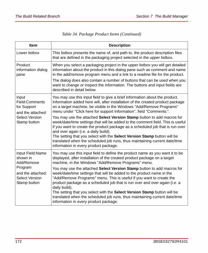
The Build Related Branch Section 7 The Build Manager
Lower listbox This listbox presents the name of, and path to, the product description files that are defined in the packaging project selected in the upper listbox.
Product information dialog pane
When you select a packaging project in the upper listbox you will get detailed information about the product in this dialog pane such as comment and name in the add/remove program menu and a link to a readme file for the product.
The dialog does also contain a number of buttons that can be used when you want to change or inspect the information. The buttons and input fields are described in detail below.
Input Field:Comments for Support
and the attached: Select Version Stamp button
You may use this input field to give a brief information about the product. Information added here will, after installation of the created product package on a target machine, be visible in the Windows "Add/Remove Programs" menu under "Click here for support Information", field "Comments:".
You may use the attached Select Version Stamp button to add macros for week/date/time settings that will be added to the comment field. This is useful if you want to create the product package as a scheduled job that is run over and over again (i.e. a daily build). The setting that you select with the Select Version Stamp button will be translated when the scheduled job runs, thus maintaining current date/time information in every product package.
Input Field:Name shown in Add/Remove Program
and the attached: Select Version Stamp button
You may use this input field to define the product name as you want it to be displayed, after installation of the created product package on a target machine, in the Windows "Add/Remove Programs" menu.
You may use the attached Select Version Stamp button to add macros for week/date/time settings that will be added to the product name in the "Add/Remove Programs" menu. This is useful if you want to create the product package as a scheduled job that is run over and over again (i.e. a daily build). The setting that you select with the Select Version Stamp button will be translated when the scheduled job runs, thus maintaining current date/time information in every product package.
Table 34. Package Product Items (Continued)
Item Description
172 3BSE032792R4101
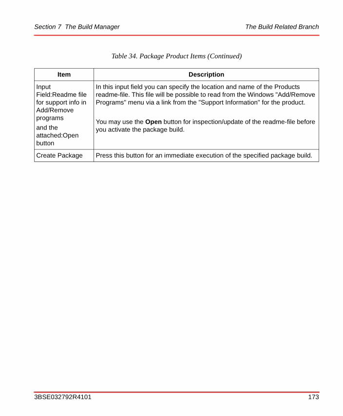
Section 7 The Build Manager The Build Related Branch
Input Field:Readme file for support info in Add/Remove programs
and the attached:Open button
In this input field you can specify the location and name of the Products readme-file. This file will be possible to read from the Windows "Add/Remove Programs" menu via a link from the "Support Information" for the product.
You may use the Open button for inspection/update of the readme-file before you activate the package build.
Create Package Press this button for an immediate execution of the specified package build.
Table 34. Package Product Items (Continued)
Item Description
3BSE032792R4101 173
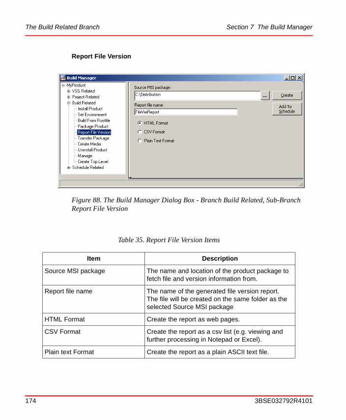
The Build Related Branch Section 7 The Build Manager
Report File Version
Figure 88. The Build Manager Dialog Box - Branch Build Related, Sub-Branch Report File Version
Table 35. Report File Version Items
Item Description
Source MSI package The name and location of the product package to fetch file and version information from.
Report file name The name of the generated file version report. The file will be created on the same folder as the selected Source MSI package
HTML Format Create the report as web pages.
CSV Format Create the report as a csv list (e.g. viewing and further processing in Notepad or Excel).
Plain text Format Create the report as a plain ASCII text file.
174 3BSE032792R4101
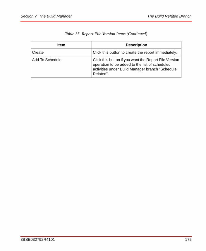
Section 7 The Build Manager The Build Related Branch
Create Click this button to create the report immediately.
Add To Schedule Click this button if you want the Report File Version operation to be added to the list of scheduled activities under Build Manager branch "Schedule Related".
Table 35. Report File Version Items (Continued)
Item Description
3BSE032792R4101 175
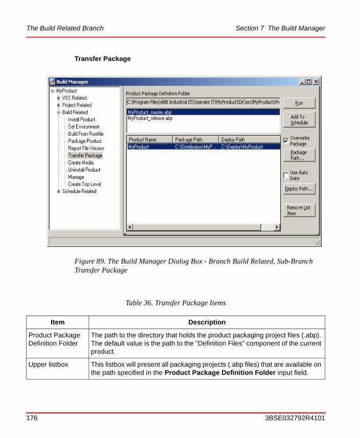
The Build Related Branch Section 7 The Build Manager
Transfer Package
Figure 89. The Build Manager Dialog Box - Branch Build Related, Sub-Branch Transfer Package
Table 36. Transfer Package Items
Item Description
Product Package Definition Folder
The path to the directory that holds the product packaging project files (.abp). The default value is the path to the "Definition Files" component of the current product.
Upper listbox This listbox will present all packaging projects (.abp files) that are available on the path specified in the Product Package Definition Folder input field.
176 3BSE032792R4101
Section 7 The Build Manager The Build Related Branch
Create Media
This function requires that a CD/DVD burning device is installed and that Nero burning software is installed. If not you will get the message shown in the figure below:
Lower listbox This listbox presents the Product Name, Package Path and Deploy Path of the selected packaging project.
Where:Product Name is the name of the product that will be transferred.Package Path is the location of the distribution package that will be transferred.Deploy Path is the path to where the package will be transferred.
Run... Press this button for an immediate execution of the specified package transfer.
Add to Schedule Click this button if you want the Transfer Package operation to be added to the list of scheduled activities under Build Manager branch "Schedule Related".
Overwrite Product Package
Check this checkbox if you want any existing old version of the package on the target path to be deleted before a new transfer starts.
Use Auto Date Check this checkbox if you want the current date to be added as an extra directory level to the Deploy Path.
Table 36. Transfer Package Items (Continued)
Item Description
3BSE032792R4101 177

The Build Related Branch Section 7 The Build Manager
But if the PC is equipped with the required CD/DVD burning tools the dialog will open with the full layout as shown in the figure below.
Figure 90. Create Media - no CD/DVD burning tools on the PC
Figure 91. The Build Manager Dialog Box - Branch Build Related, Sub-Branch Create Media
178 3BSE032792R4101
Section 7 The Build Manager The Build Related Branch
Table 37. Create Media Items
Item Description
Select Burn Root Folder In this window pane you will specify:
• The path to the top level folder that contains the folders and files you want to burn
• A selection of folders (i.e you can unselect some of the folders under the top folder). You can unselect all folders by clicking the button "Unselect All".
Please note the first list entry "Include files in burn folder". This is checkmarked by default and will make sure that all files on top levels are included. Uncheck this list entry if you want the media to contain only the selected subfolders and their content.
There is also a size bar that shows how much space will be left on the target CD/DVD ROM. The content of the size bar can be updated by clicking the "Refresh Size Bar" button.
CD/DVD Volume Label Specify the label you want on the created CV/DVD ROM
Media Type Specify the type of output media by selecting one of the types available in the list.
Burning Speed Select burning speed from the list.
Available Burning Devices Select the burner you want to use for the media creation
Simulate Burning First Checkmark this if you want the burning process to perform a simulation
Burn with Verification Checkmark this if you want the burning process to perform a media verification
3BSE032792R4101 179
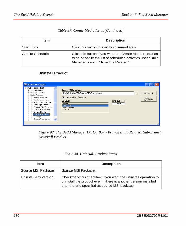
The Build Related Branch Section 7 The Build Manager
Uninstall Product
Start Burn Click this button to start burn immediately
Add To Schedule Click this button if you want the Create Media operation to be added to the list of scheduled activities under Build Manager branch "Schedule Related".
Figure 92. The Build Manager Dialog Box - Branch Build Related, Sub-Branch Uninstall Product
Table 38. Uninstall Product Items
Item Descrpition
Source MSI Package Source MSI Package.
Uninstall any version Checkmark this checkbox if you want the uninstall operation to uninstall the product even if there is another version installed than the one specified as source MSI package
Table 37. Create Media Items (Continued)
Item Description
180 3BSE032792R4101
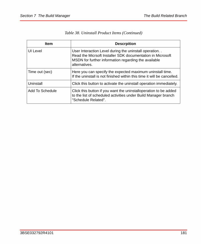
Section 7 The Build Manager The Build Related Branch
UI Level User Interaction Level during the uninstall operation. . Read the Micrsoft Installer SDK documentation in Microsoft MSDN for further information regarding the available alternatives.
Time out (sec) Here you can specify the expected maximum uninstall time. If the uninstall is not finished within this time it will be cancelled.
Uninstall Click this button to activate the uninstall operation immediately.
Add To Schedule Click this button if you want the uninstalloperation to be added to the list of scheduled activities under Build Manager branch "Schedule Related".
Table 38. Uninstall Product Items (Continued)
Item Descrpition
3BSE032792R4101 181
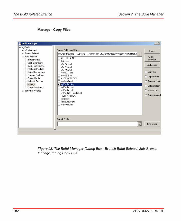
The Build Related Branch Section 7 The Build Manager
Manage - Copy Files
Figure 93. The Build Manager Dialog Box - Branch Build Related, Sub-Branch Manage, dialog Copy File
182 3BSE032792R4101
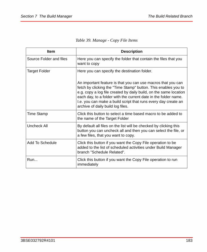
Section 7 The Build Manager The Build Related Branch
Table 39. Manage - Copy File Items
Item Description
Source Folder and files Here you can specify the folder that contain the files that you want to copy
Target Folder Here you can specify the destination folder.
An important feature is that you can use macros that you can fetch by clicking the "Time Stamp" button. This enables you to e.g. copy a log file created by daily build, on the same location each day, to a folder with the current date in the folder name. I.e. you can make a build script that runs every day create an archive of daily build log files.
Time Stamp Click this button to select a time based macro to be added to the name of the Target Folder
Uncheck All By default all files on the list will be checked by clicking this button you can uncheck all and then you can select the file, or a few files, that you want to copy.
Add To Schedule Click this button if you want the Copy File operation to be added to the list of scheduled activities under Build Manager branch "Schedule Related".
Run... Click this button if you want the Copy File operation to run immediately
3BSE032792R4101 183
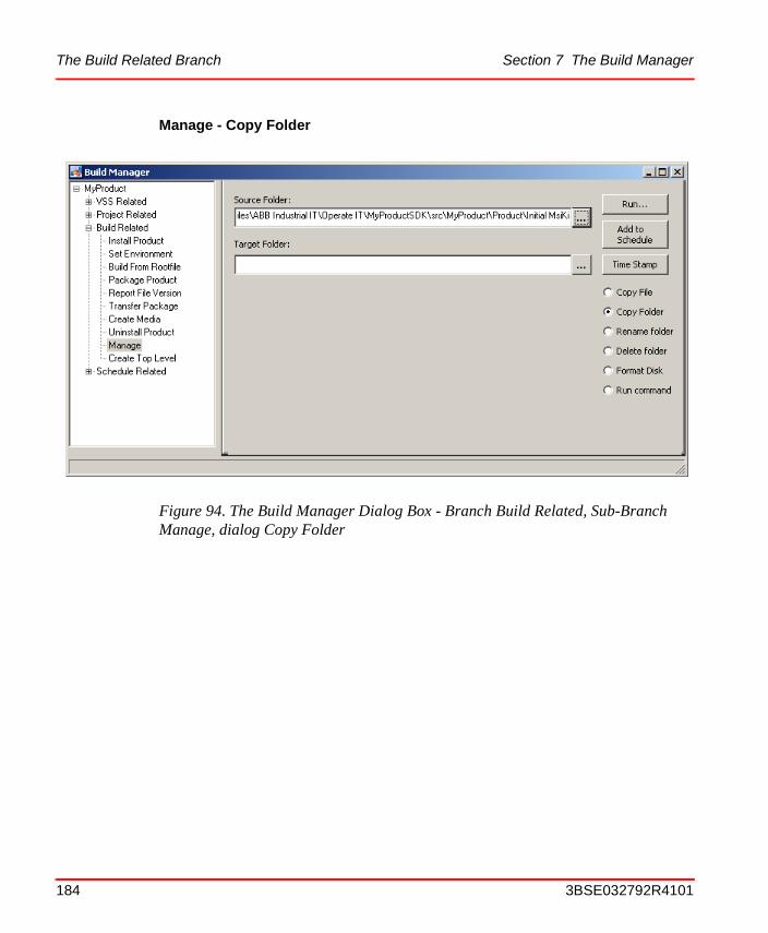
The Build Related Branch Section 7 The Build Manager
Manage - Copy Folder
Figure 94. The Build Manager Dialog Box - Branch Build Related, Sub-Branch Manage, dialog Copy Folder
184 3BSE032792R4101

Section 7 The Build Manager The Build Related Branch
Table 40. Manage - Copy Folder Items
Item Description
Source Folder Here you can specify the folder that you want to copy
Target Folder Here you can specify the destination folder.
An important feature is that you can use macros that you can fetch by clicking the "Time Stamp" button". This enables you to e.g. copy a folder created by daily build, on the same location each day, to a folder with the current date in the folder name.
Time Stamp Click this button to select a time based macro to be added to the name of the Target Folder.
Uncheck All By default all files on the list will be checked by clicking this button you can uncheck all and then you can select the file, or a few files, that you want to copy.
Add To Schedule Click this button if you want the Copy Folder operation to be added to the list of scheduled activities under Build Manager branch "Schedule Related".
Run... Click this button if you want the Copy Folder operation to run immediately.
3BSE032792R4101 185
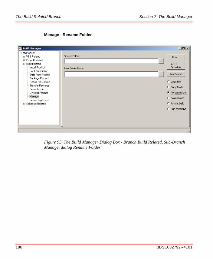
The Build Related Branch Section 7 The Build Manager
Menage - Rename Folder
Figure 95. The Build Manager Dialog Box - Branch Build Related, Sub-Branch Manage, dialog Rename Folder
186 3BSE032792R4101
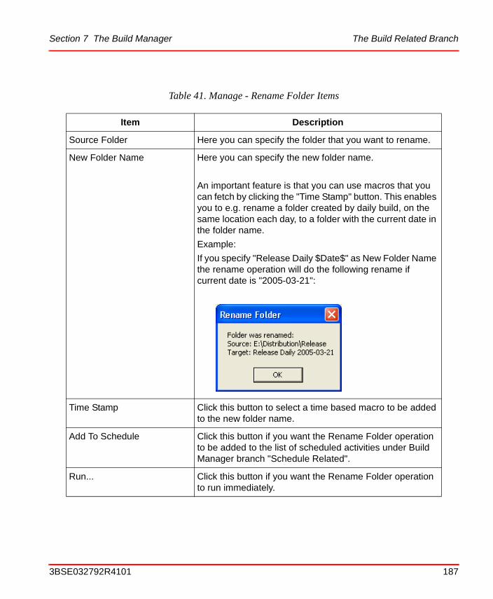
Section 7 The Build Manager The Build Related Branch
Table 41. Manage - Rename Folder Items
Item Description
Source Folder Here you can specify the folder that you want to rename.
New Folder Name Here you can specify the new folder name.
An important feature is that you can use macros that you can fetch by clicking the "Time Stamp" button. This enables you to e.g. rename a folder created by daily build, on the same location each day, to a folder with the current date in the folder name.
Example:
If you specify "Release Daily $Date$" as New Folder Name the rename operation will do the following rename if current date is "2005-03-21":
Time Stamp Click this button to select a time based macro to be added to the new folder name.
Add To Schedule Click this button if you want the Rename Folder operation to be added to the list of scheduled activities under Build Manager branch "Schedule Related".
Run... Click this button if you want the Rename Folder operation to run immediately.
3BSE032792R4101 187
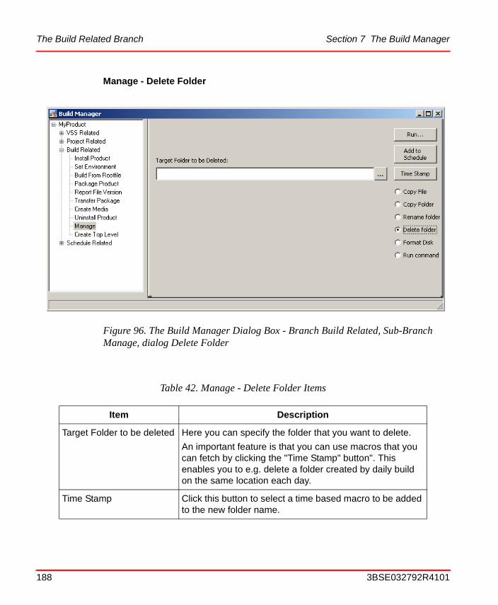
The Build Related Branch Section 7 The Build Manager
Manage - Delete Folder
Figure 96. The Build Manager Dialog Box - Branch Build Related, Sub-Branch Manage, dialog Delete Folder
Table 42. Manage - Delete Folder Items
Item Description
Target Folder to be deleted Here you can specify the folder that you want to delete.
An important feature is that you can use macros that you can fetch by clicking the "Time Stamp" button". This enables you to e.g. delete a folder created by daily build on the same location each day.
Time Stamp Click this button to select a time based macro to be added to the new folder name.
188 3BSE032792R4101
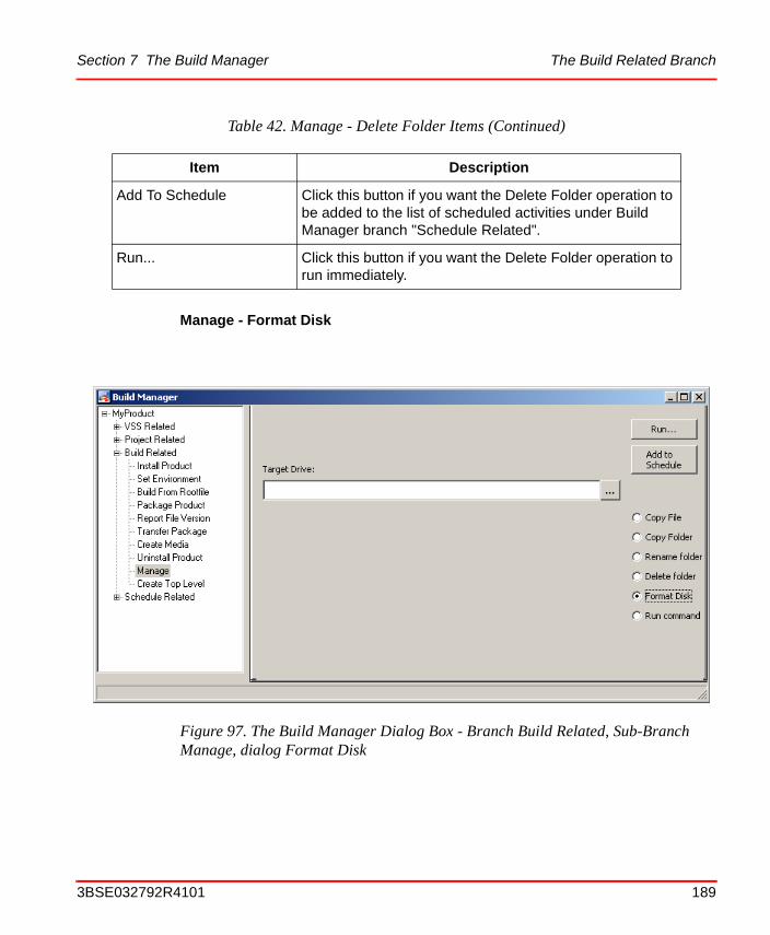
Section 7 The Build Manager The Build Related Branch
Manage - Format Disk
Add To Schedule Click this button if you want the Delete Folder operation to be added to the list of scheduled activities under Build Manager branch "Schedule Related".
Run... Click this button if you want the Delete Folder operation to run immediately.
Figure 97. The Build Manager Dialog Box - Branch Build Related, Sub-Branch Manage, dialog Format Disk
Table 42. Manage - Delete Folder Items (Continued)
Item Description
3BSE032792R4101 189

The Build Related Branch Section 7 The Build Manager
Table 43. Manage - Format Disk Items
Item Description
Target Drive Here you can specify the device that you want to format.
Add To Schedule Click this button if you want the Delete Format Disk operation to be added to the list of scheduled activities under Build Manager branch "Schedule Related".
Please Note! Disk formatting is a critical operation and will require a user acknowledgement even when scheduled (run as part of e.g. a daily build job).
If possible, and if you don't want your script to be interrupted e.g. in the middle of a daily build job, you must structure your scheduled job to have disk formatting in the beginning or at the end.
Run... Click this button if you want the Format Disk operation to run immediately.
190 3BSE032792R4101
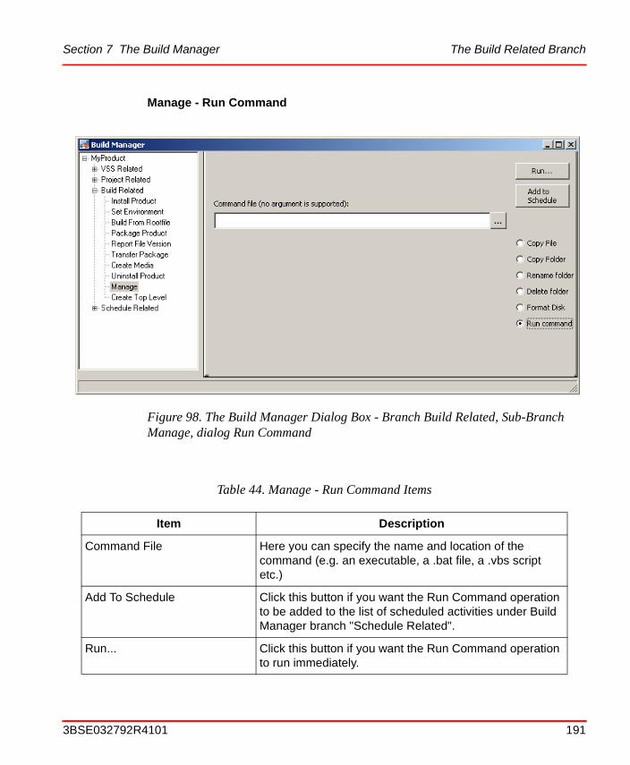
Section 7 The Build Manager The Build Related Branch
Manage - Run Command
Figure 98. The Build Manager Dialog Box - Branch Build Related, Sub-Branch Manage, dialog Run Command
Table 44. Manage - Run Command Items
Item Description
Command File Here you can specify the name and location of the command (e.g. an executable, a .bat file, a .vbs script etc.)
Add To Schedule Click this button if you want the Run Command operation to be added to the list of scheduled activities under Build Manager branch "Schedule Related".
Run... Click this button if you want the Run Command operation to run immediately.
3BSE032792R4101 191

The Build Related Branch Section 7 The Build Manager
Create Top Level
Figure 99. The Build Manager Dialog Box - Branch Build Related, Sub-Branch Create Top Level
192 3BSE032792R4101
Section 7 The Build Manager The Schedule Related Branch
The Schedule Related Branch
For larger products it might take quite some time to perform all the build activities, as they will access large data areas in VSS and on the disk workspace. Furthermore, the different Build Manager tools must be executed in a certain order within a project. You must, for example, create a VSS baseline before you can fetch the project from the VSS database to your workspace, and you must compile and link all components before you can build the MSMs.
In order to shorten the time a project integrator has to spend waiting for activation of the next step, the Build Manager provides a Scheduler tool.
When the user creates a baseline, fetches the baseline, and starts the build operation he can, instead of activating each step one at a time, specify that he wants each activity to be scheduled for later execution, in batch or interactive mode. What happens then, is that instead of activating the corresponding tools immediately, the Build Manager records each activity in a Visual Basic script for later run.
When the user has specified all the required build activities, he can activate the Scheduler tool. The Scheduler will then present a list of all jobs that has been set up (that is all VB scripts). Then the user can sort the jobs in the list in the order he wants the operations to be executed by using the Move Up and Move Down buttons.
Table 45. Create Top Level Items
Item Description
Package distribution root folder The anchor directory of your product distributions.
Edit Top Level When you press this button the autorun.inf editor will open and it will show the current top level with all products. For details see Customize the Autoplay Dialog on page 262. If a top level is missing when you press the button it will be created and populated with all products that are found beneath the specified package distribution root folder.
Add to Schedule Click this button if you want the top level creation to be added to the list of scheduled activities under Build Manager branch "Schedule Related".
3BSE032792R4101 193
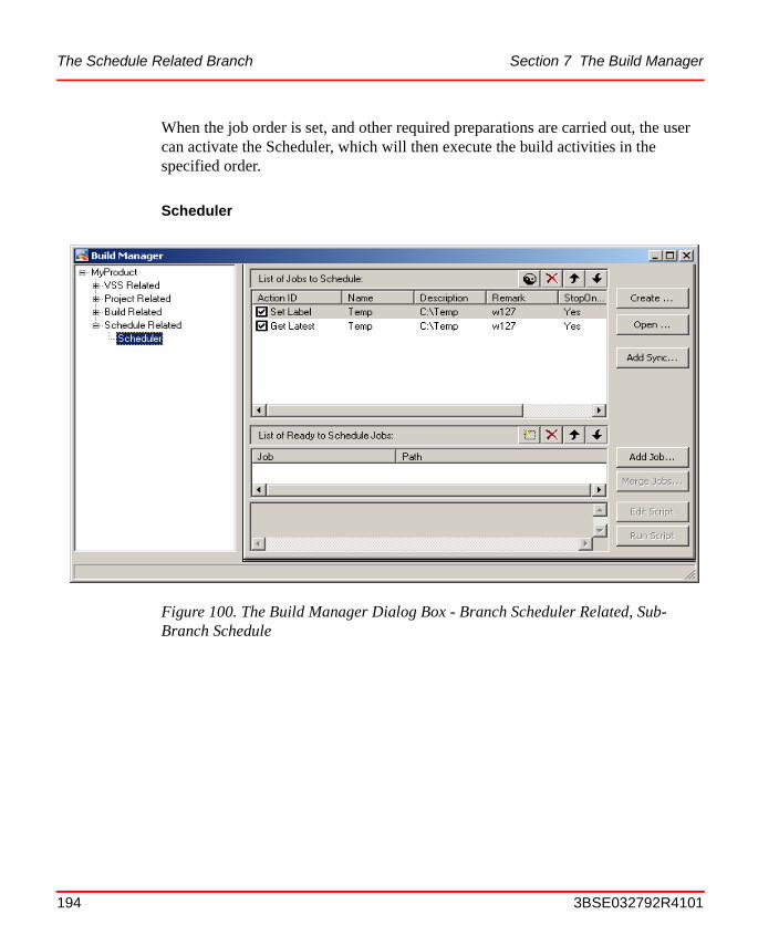
The Schedule Related Branch Section 7 The Build Manager
When the job order is set, and other required preparations are carried out, the user can activate the Scheduler, which will then execute the build activities in the specified order.
Scheduler
Figure 100. The Build Manager Dialog Box - Branch Scheduler Related, Sub-Branch Schedule
194 3BSE032792R4101
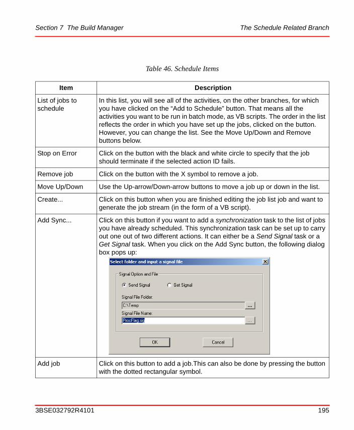
Section 7 The Build Manager The Schedule Related Branch
Table 46. Schedule Items
Item Description
List of jobs to schedule
In this list, you will see all of the activities, on the other branches, for which you have clicked on the “Add to Schedule” button. That means all the activities you want to be run in batch mode, as VB scripts. The order in the list reflects the order in which you have set up the jobs, clicked on the button. However, you can change the list. See the Move Up/Down and Remove buttons below.
Stop on Error Click on the button with the black and white circle to specify that the job should terminate if the selected action ID fails.
Remove job Click on the button with the X symbol to remove a job.
Move Up/Down Use the Up-arrow/Down-arrow buttons to move a job up or down in the list.
Create... Click on this button when you are finished editing the job list job and want to generate the job stream (in the form of a VB script).
Add Sync... Click on this button if you want to add a synchronization task to the list of jobs you have already scheduled. This synchronization task can be set up to carry out one out of two different actions. It can either be a Send Signal task or a Get Signal task. When you click on the Add Sync button, the following dialog box pops up:
Add job Click on this button to add a job.This can also be done by pressing the button with the dotted rectangular symbol.
3BSE032792R4101 195
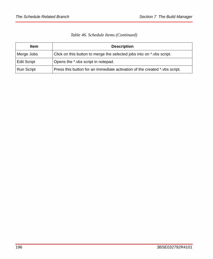
The Schedule Related Branch Section 7 The Build Manager
Merge Jobs Click on this button to merge the selected jobs into on *.vbs script.
Edit Script Opens the *.vbs script in notepad.
Run Script Press this button for an immediate activation of the created *.vbs script.
Table 46. Schedule Items (Continued)
Item Description
196 3BSE032792R4101
Section 8 The AutoBuild Tool
AutoBuild is to be set up as an add-in module to MS Visual Studio, see Setting up the AutoBuild Add-ins on page 198
AutoBuild simplifies the build process by providing dialogs, opened in MS Visual Studio, which are adapted to the Aspect Studio/PPA environment. In other words, AutoBuild is an adapter which transforms the Aspect Studio/PPA environment concepts to the MS Visual Studio environment, thus relieving the user from the need to enter the corresponding commands to MS Visual Studio.
There are three dialogs for accessing AutoBuild:
• Configure AutoBuild
• AutoBuild
• Quick Build
For a detailed description of these interfaces, see Configure AutoBuild on page 200 and Run AutoBuild on page 207.
3BSE032792R4101 197
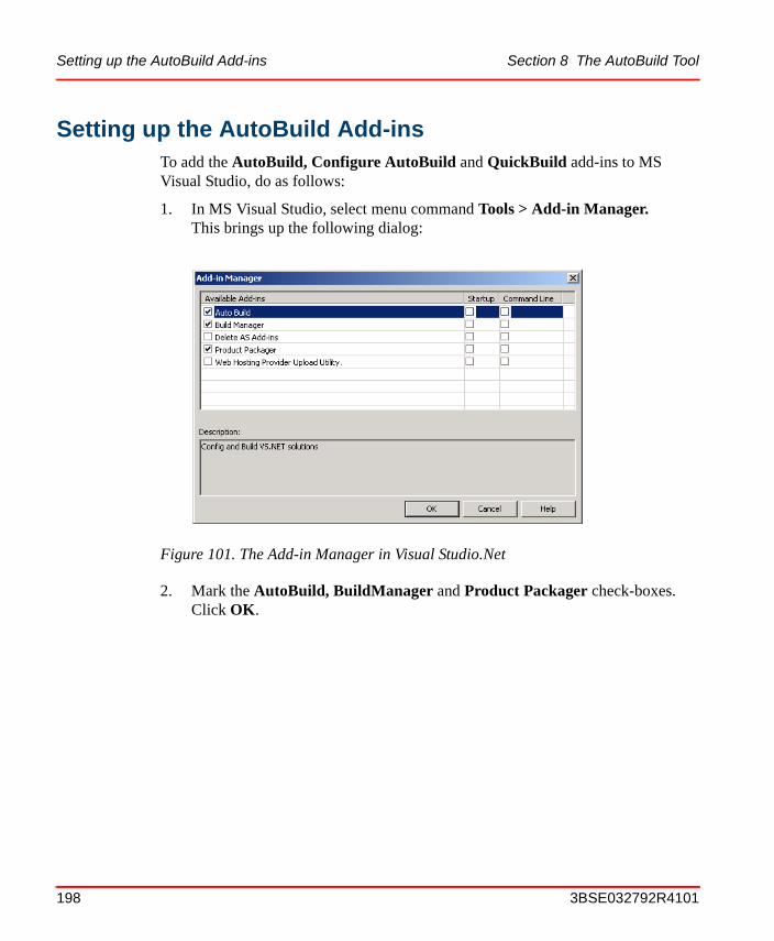
Setting up the AutoBuild Add-ins Section 8 The AutoBuild Tool
Setting up the AutoBuild Add-insTo add the AutoBuild, Configure AutoBuild and QuickBuild add-ins to MS Visual Studio, do as follows:
1. In MS Visual Studio, select menu command Tools > Add-in Manager.This brings up the following dialog:
2. Mark the AutoBuild, BuildManager and Product Packager check-boxes. Click OK.
Figure 101. The Add-in Manager in Visual Studio.Net
198 3BSE032792R4101
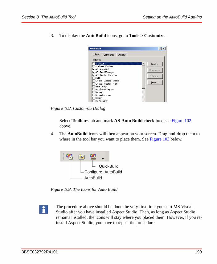
Section 8 The AutoBuild Tool Setting up the AutoBuild Add-ins
3. To display the AutoBuild icons, go to Tools > Customize.
Select Toolbars tab and mark AS-Auto Build check-box, see Figure 102 above.
4. The AutoBuild icons will then appear on your screen. Drag-and-drop them to where in the tool bar you want to place them. See Figure 103 below.
Figure 102. Customize Dialog
Figure 103. The Icons for Auto Build
The procedure above should be done the very first time you start MS Visual Studio after you have installed Aspect Studio. Then, as long as Aspect Studio remains installed, the icons will stay where you placed them. However, if you re-install Aspect Studio, you have to repeat the procedure.
Configure AutoBuild
AutoBuild
QuickBuild
3BSE032792R4101 199

Configure AutoBuild Section 8 The AutoBuild Tool
Configure AutoBuild
Build Visual Studio Projects
When you click on the Configure AutoBuild icon and then on the Build Visual Studio Projects radio button, the settings for the Build function appears, see Figure 104.
Figure 104. The Configuring AutoBuild Dialog
200 3BSE032792R4101
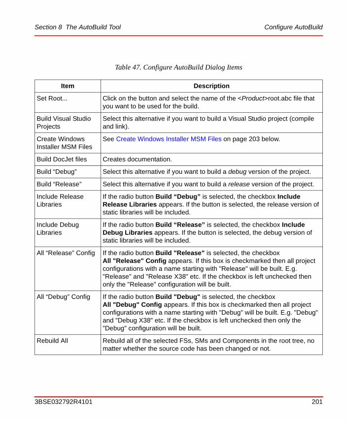
Section 8 The AutoBuild Tool Configure AutoBuild
Table 47. Configure AutoBuild Dialog Items
Item Description
Set Root... Click on the button and select the name of the <Product>root.abc file that you want to be used for the build.
Build Visual Studio Projects
Select this alternative if you want to build a Visual Studio project (compile and link).
Create Windows Installer MSM Files
See Create Windows Installer MSM Files on page 203 below.
Build DocJet files Creates documentation.
Build “Debug” Select this alternative if you want to build a debug version of the project.
Build “Release” Select this alternative if you want to build a release version of the project.
Include Release Libraries
If the radio button Build “Debug” is selected, the checkbox Include Release Libraries appears. If the button is selected, the release version of static libraries will be included.
Include Debug Libraries
If the radio button Build “Release” is selected, the checkbox Include Debug Libraries appears. If the button is selected, the debug version of static libraries will be included.
All “Release” Config If the radio button Build "Release" is selected, the checkboxAll "Release" Config appears. If this box is checkmarked then all project configurations with a name starting with "Release" will be built. E.g. "Release" and "Release X38" etc. If the checkbox is left unchecked then only the "Release" configuration will be built.
All “Debug” Config If the radio button Build "Debug" is selected, the checkboxAll "Debug" Config appears. If this box is checkmarked then all project configurations with a name starting with "Debug" will be built. E.g. "Debug" and "Debug X38" etc. If the checkbox is left unchecked then only the "Debug" configuration will be built.
Rebuild All Rebuild all of the selected FSs, SMs and Components in the root tree, no matter whether the source code has been changed or not.
3BSE032792R4101 201
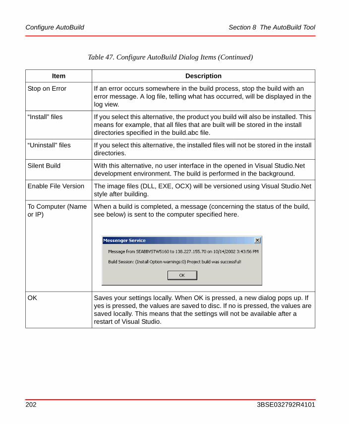
Configure AutoBuild Section 8 The AutoBuild Tool
Stop on Error If an error occurs somewhere in the build process, stop the build with an error message. A log file, telling what has occurred, will be displayed in the log view.
“Install” files If you select this alternative, the product you build will also be installed. This means for example, that all files that are built will be stored in the install directories specified in the build.abc file.
“Uninstall” files If you select this alternative, the installed files will not be stored in the install directories.
Silent Build With this alternative, no user interface in the opened in Visual Studio.Net development environment. The build is performed in the background.
Enable File Version The image files (DLL, EXE, OCX) will be versioned using Visual Studio.Net style after building.
To Computer (Name or IP)
When a build is completed, a message (concerning the status of the build, see below) is sent to the computer specified here.
OK Saves your settings locally. When OK is pressed, a new dialog pops up. If yes is pressed, the values are saved to disc. If no is pressed, the values are saved locally. This means that the settings will not be available after a restart of Visual Studio.
Table 47. Configure AutoBuild Dialog Items (Continued)
Item Description
202 3BSE032792R4101
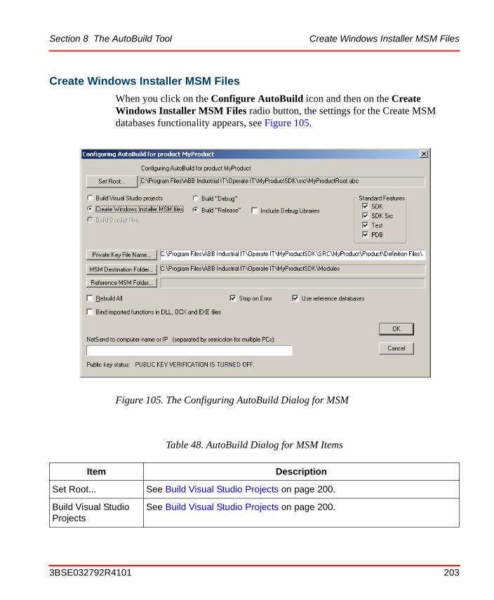
Section 8 The AutoBuild Tool Create Windows Installer MSM Files
Create Windows Installer MSM Files
When you click on the Configure AutoBuild icon and then on the Create Windows Installer MSM Files radio button, the settings for the Create MSM databases functionality appears, see Figure 105.
Figure 105. The Configuring AutoBuild Dialog for MSM
Table 48. AutoBuild Dialog for MSM Items
Item Description
Set Root... See Build Visual Studio Projects on page 200.
Build Visual Studio Projects
See Build Visual Studio Projects on page 200.
3BSE032792R4101 203
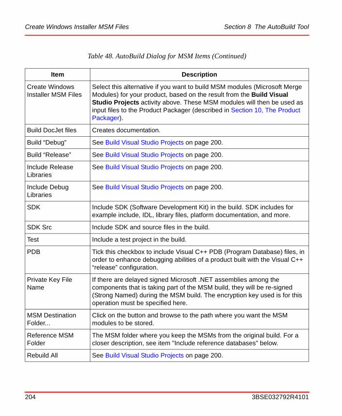
Create Windows Installer MSM Files Section 8 The AutoBuild Tool
Create Windows Installer MSM Files
Select this alternative if you want to build MSM modules (Microsoft Merge Modules) for your product, based on the result from the Build Visual Studio Projects activity above. These MSM modules will then be used as input files to the Product Packager (described in Section 10, The Product Packager).
Build DocJet files Creates documentation.
Build “Debug” See Build Visual Studio Projects on page 200.
Build “Release” See Build Visual Studio Projects on page 200.
Include Release Libraries
See Build Visual Studio Projects on page 200.
Include Debug Libraries
See Build Visual Studio Projects on page 200.
SDK Include SDK (Software Development Kit) in the build. SDK includes for example include, IDL, library files, platform documentation, and more.
SDK Src Include SDK and source files in the build.
Test Include a test project in the build.
PDB Tick this checkbox to include Visual C++ PDB (Program Database) files, in order to enhance debugging abilities of a product built with the Visual C++ “release” configuration.
Private Key File Name
If there are delayed signed Microsoft .NET assemblies among the components that is taking part of the MSM build, they will be re-signed (Strong Named) during the MSM build. The encryption key used is for this operation must be specified here.
MSM Destination Folder...
Click on the button and browse to the path where you want the MSM modules to be stored.
Reference MSM Folder
The MSM folder where you keep the MSMs from the original build. For a closer description, see item "Include reference databases" below.
Rebuild All See Build Visual Studio Projects on page 200.
Table 48. AutoBuild Dialog for MSM Items (Continued)
Item Description
204 3BSE032792R4101

Section 8 The AutoBuild Tool Create Windows Installer MSM Files
Stop on Error See Build Visual Studio Projects on page 200.
Use reference databases
Tick this checkbox when you are going to create MSMs for a Service Pack. When you tick this box, a new button labeled Reference MSM Folder... pops up. Click on that button to specify the MSM folder where you keep the MSMs from the original (full) product package build. Normally this is a folder on a CD which contains a full build (a MASTER) of the product for which you are going to create the Service Pack. That is a build in which you, in the Product Packager, selected to include all categories of MSMs.
To tick the Use reference databases checkbox and to specify a Reference MSM Folder is important when you create MSMs for a Service Pack. By using this information, the MSM builder will be able to recognize and reuse component IDs.
This feature should always be selected to avoid getting a number of components containing the same files (component GUIDs will be re-generated each time the MSM is rebuilt if no ref. MSM is specified). Performance will also increase as an MSM will only be rebuilt if its content has changed.
Bind imported functions in DLL, OCX and EXE files
This function uses the MS installer function. This is used for performance reasons.
Table 48. AutoBuild Dialog for MSM Items (Continued)
Item Description
3BSE032792R4101 205
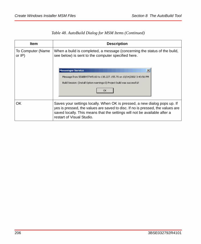
Create Windows Installer MSM Files Section 8 The AutoBuild Tool
To Computer (Name or IP)
When a build is completed, a message (concerning the status of the build, see below) is sent to the computer specified here.
OK Saves your settings locally. When OK is pressed, a new dialog pops up. If yes is pressed, the values are saved to disc. If no is pressed, the values are saved locally. This means that the settings will not be available after a restart of Visual Studio.
Table 48. AutoBuild Dialog for MSM Items (Continued)
Item Description
206 3BSE032792R4101
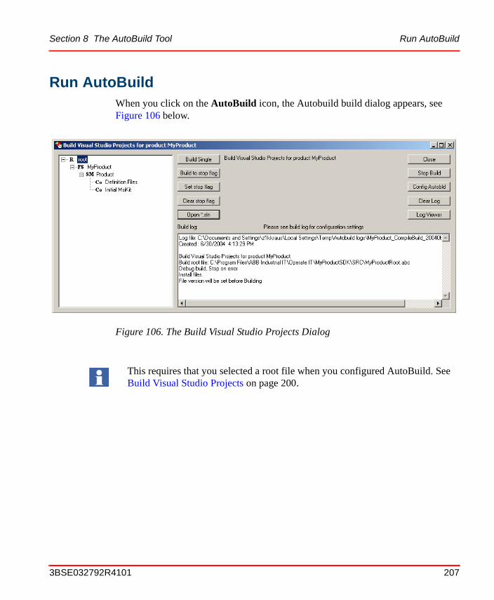
Section 8 The AutoBuild Tool Run AutoBuild
Run AutoBuildWhen you click on the AutoBuild icon, the Autobuild build dialog appears, see Figure 106 below.
Figure 106. The Build Visual Studio Projects Dialog
This requires that you selected a root file when you configured AutoBuild. See Build Visual Studio Projects on page 200.
3BSE032792R4101 207
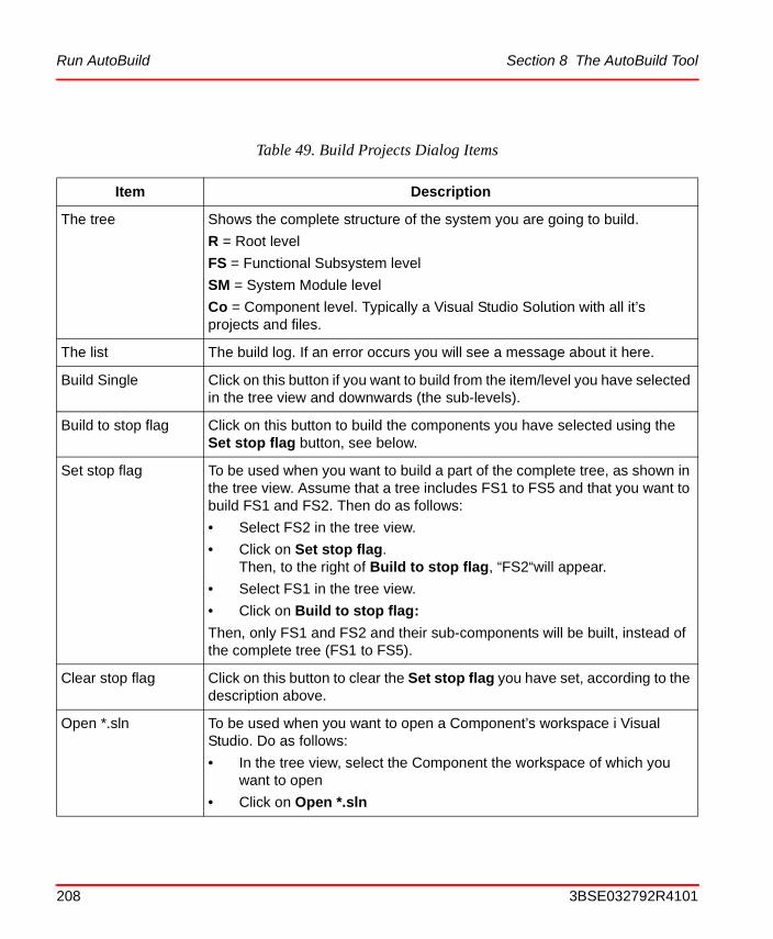
Run AutoBuild Section 8 The AutoBuild Tool
Table 49. Build Projects Dialog Items
Item Description
The tree Shows the complete structure of the system you are going to build.
R = Root level
FS = Functional Subsystem level
SM = System Module level
Co = Component level. Typically a Visual Studio Solution with all it’s projects and files.
The list The build log. If an error occurs you will see a message about it here.
Build Single Click on this button if you want to build from the item/level you have selected in the tree view and downwards (the sub-levels).
Build to stop flag Click on this button to build the components you have selected using the Set stop flag button, see below.
Set stop flag To be used when you want to build a part of the complete tree, as shown in the tree view. Assume that a tree includes FS1 to FS5 and that you want to build FS1 and FS2. Then do as follows:
• Select FS2 in the tree view.
• Click on Set stop flag.Then, to the right of Build to stop flag, “FS2“will appear.
• Select FS1 in the tree view.
• Click on Build to stop flag:
Then, only FS1 and FS2 and their sub-components will be built, instead of the complete tree (FS1 to FS5).
Clear stop flag Click on this button to clear the Set stop flag you have set, according to the description above.
Open *.sln To be used when you want to open a Component’s workspace i Visual Studio. Do as follows:
• In the tree view, select the Component the workspace of which you want to open
• Click on Open *.sln
208 3BSE032792R4101
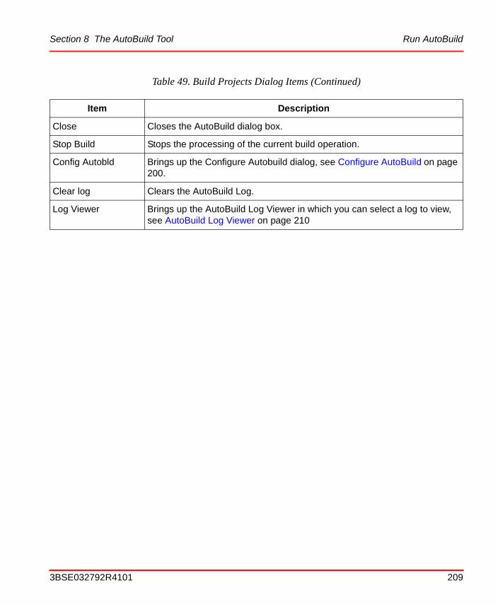
Section 8 The AutoBuild Tool Run AutoBuild
Close Closes the AutoBuild dialog box.
Stop Build Stops the processing of the current build operation.
Config Autobld Brings up the Configure Autobuild dialog, see Configure AutoBuild on page 200.
Clear log Clears the AutoBuild Log.
Log Viewer Brings up the AutoBuild Log Viewer in which you can select a log to view, see AutoBuild Log Viewer on page 210
Table 49. Build Projects Dialog Items (Continued)
Item Description
3BSE032792R4101 209
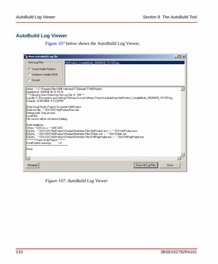
AutoBuild Log Viewer Section 8 The AutoBuild Tool
AutoBuild Log Viewer
Figure 107 below shows the AutoBuild Log Viewer.
Figure 107. AutoBuild Log Viewer
210 3BSE032792R4101

Section 8 The AutoBuild Tool QuickBuild
QuickBuildQuickBuild builds the current opened solution, in Visual Studio.Net, without loading the whole build tree. The effectivity of compile/link and install is increased.
Table 50. AutoBuild Log Viewer Items
Item Description
View Log Files Here you select the type of project corresponding to AutoBuild dialog.
Top list A list of the existing log files. Double click on a log file to show the log file in details.
Bottom window Shows the log file selected in the top list. If the log file is larger than 64K, it is divided into multiple pages. Following browsing buttons are shown.
Notepad By clicking on this button the selected log file will be opened in the notepad editor (so you can search for build errors etc.).
Show All Log Files By clicking this button all log files are displayed in Windows Explorer. There you can delete unwanted log files.
3BSE032792R4101 211
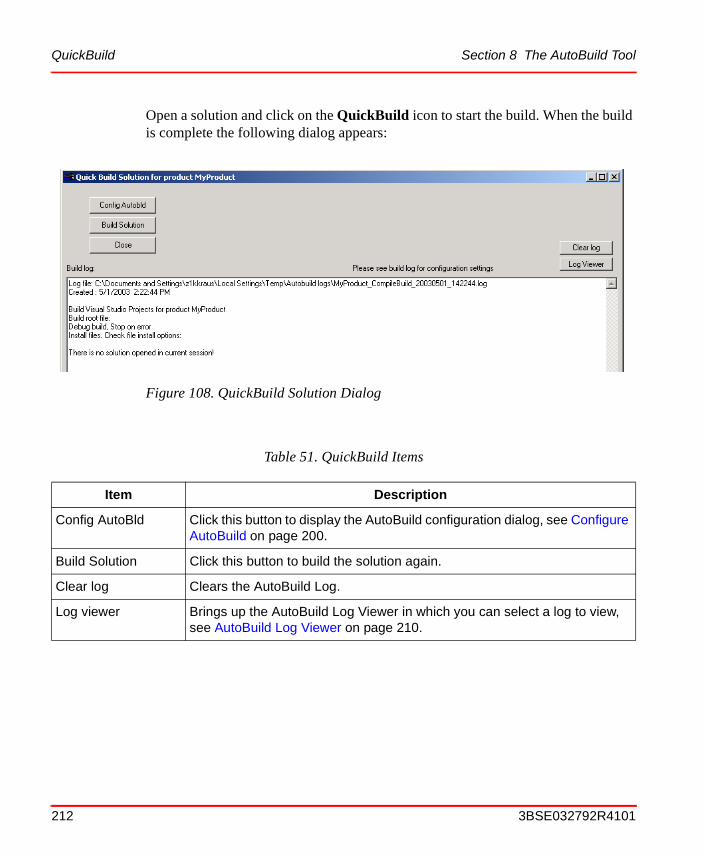
QuickBuild Section 8 The AutoBuild Tool
Open a solution and click on the QuickBuild icon to start the build. When the build is complete the following dialog appears:
Figure 108. QuickBuild Solution Dialog
Table 51. QuickBuild Items
Item Description
Config AutoBld Click this button to display the AutoBuild configuration dialog, see Configure AutoBuild on page 200.
Build Solution Click this button to build the solution again.
Clear log Clears the AutoBuild Log.
Log viewer Brings up the AutoBuild Log Viewer in which you can select a log to view, see AutoBuild Log Viewer on page 210.
212 3BSE032792R4101
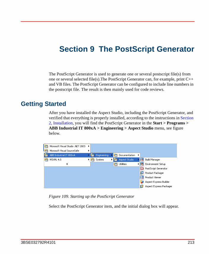
Section 9 The PostScript Generator
The PostScript Generator is used to generate one or several postscript file(s) from one or several selected file(s).The PostScript Generator can, for example, print C++ and VB files. The PostScript Generator can be configured to include line numbers in the postscript file. The result is then mainly used for code reviews.
Getting StartedAfter you have installed the Aspect Studio, including the PostScript Generator, and verified that everything is properly installed, according to the instructions in Section 2, Installation, you will find the PostScript Generator in the Start > Programs > ABB Industrial IT 800xA > Engineering > Aspect Studio menu, see figure below.
Select the PostScript Generator item, and the initial dialog box will appear.
Figure 109. Starting up the PostScript Generator
3BSE032792R4101 213
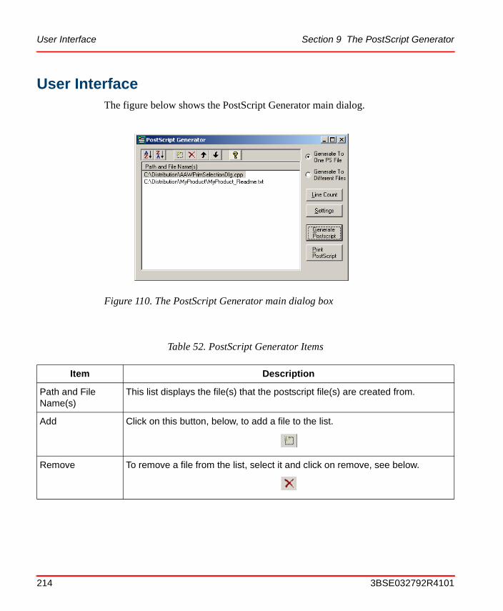
User Interface Section 9 The PostScript Generator
User InterfaceThe figure below shows the PostScript Generator main dialog.
Figure 110. The PostScript Generator main dialog box
Table 52. PostScript Generator Items
Item Description
Path and File Name(s)
This list displays the file(s) that the postscript file(s) are created from.
Add Click on this button, below, to add a file to the list.
Remove To remove a file from the list, select it and click on remove, see below.
214 3BSE032792R4101
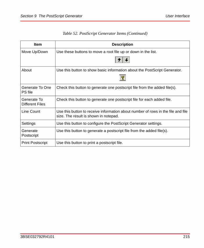
Section 9 The PostScript Generator User Interface
Move Up/Down Use these buttons to move a root file up or down in the list.
About Use this button to show basic information about the PostScript Generator.
Generate To One PS file
Check this button to generate one postscript file from the added file(s).
Generate To Different Files
Check this button to generate one postscript file for each added file.
Line Count Use this button to receive information about number of rows in the file and file size. The result is shown in notepad.
Settings Use this button to configure the PostScript Generator settings.
Generate Postscript
Use this button to generate a postscript file from the added file(s).
Print Postscript Use this button to print a postscript file.
Table 52. PostScript Generator Items (Continued)
Item Description
3BSE032792R4101 215
User Interface Section 9 The PostScript Generator
216 3BSE032792R4101
Section 10 The Product Packager
What You Can Do with the Product PackagerThe Product Packager includes tools for creation and handling of MSI compliant product distributions. Using the Product Packager for all Windows 2000, XP and Windows 2003 server based products means that there will be a consistent handling of all products, thus making the process more safe and efficient.
This is a summary of what you can do:
• Create MSI compliant product software packages.
• Create MSI compliant service packs.
• Create MSI compliant patch packs.
• Create MSI compliant extension packs.
Since the created software packages are MSI compliant, the Microsoft Windows Installer can be used to install the packages, and to remove/change the features of already installed software packages.
Setting of version on Service Packs and Patches
During a products life time it is important that it can be updated with install packages containing single minor updates (patches), a group of minor updates (rollups) and enhancements (Service Packs). It is also important that patches, rollups and Service Packs can be installed at different customer sites at a point in time suitable for the customer. These requirements leads to a complex maintenance scenario where different Service Pack levels of the product needs to be maintained with patches in parallel.
To make it possible to handle this situation, the Product Packager supports the following scheme for the setting of product version:
3BSE032792R4101 217
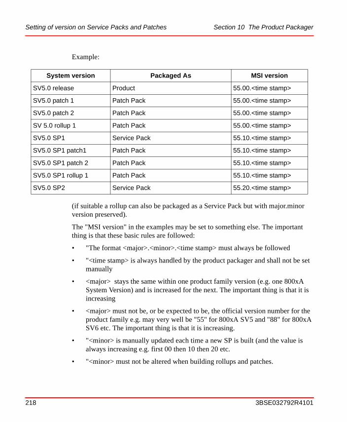
Setting of version on Service Packs and Patches Section 10 The Product Packager
Example:
(if suitable a rollup can also be packaged as a Service Pack but with major.minor version preserved).
The "MSI version" in the examples may be set to something else. The important thing is that these basic rules are followed:
• "The format <major>.<minor>.<time stamp> must always be followed
• "<time stamp> is always handled by the product packager and shall not be set manually
• <major> stays the same within one product family version (e.g. one 800xA System Version) and is increased for the next. The important thing is that it is increasing
• <major> must not be, or be expected to be, the official version number for the product family e.g. may very well be "55" for 800xA SV5 and "88" for 800xA SV6 etc. The important thing is that it is increasing.
• "<minor> is manually updated each time a new SP is built (and the value is always increasing e.g. first 00 then 10 then 20 etc.
• "<minor> must not be altered when building rollups and patches.
System version Packaged As MSI version
SV5.0 release Product 55.00.<time stamp>
SV5.0 patch 1 Patch Pack 55.00.<time stamp>
SV5.0 patch 2 Patch Pack 55.00.<time stamp>
SV 5.0 rollup 1 Patch Pack 55.00.<time stamp>
SV5.0 SP1 Service Pack 55.10.<time stamp>
SV5.0 SP1 patch1 Patch Pack 55.10.<time stamp>
SV5.0 SP1 patch 2 Patch Pack 55.10.<time stamp>
SV5.0 SP1 rollup 1 Patch Pack 55.10.<time stamp>
SV5.0 SP2 Service Pack 55.20.<time stamp>
218 3BSE032792R4101
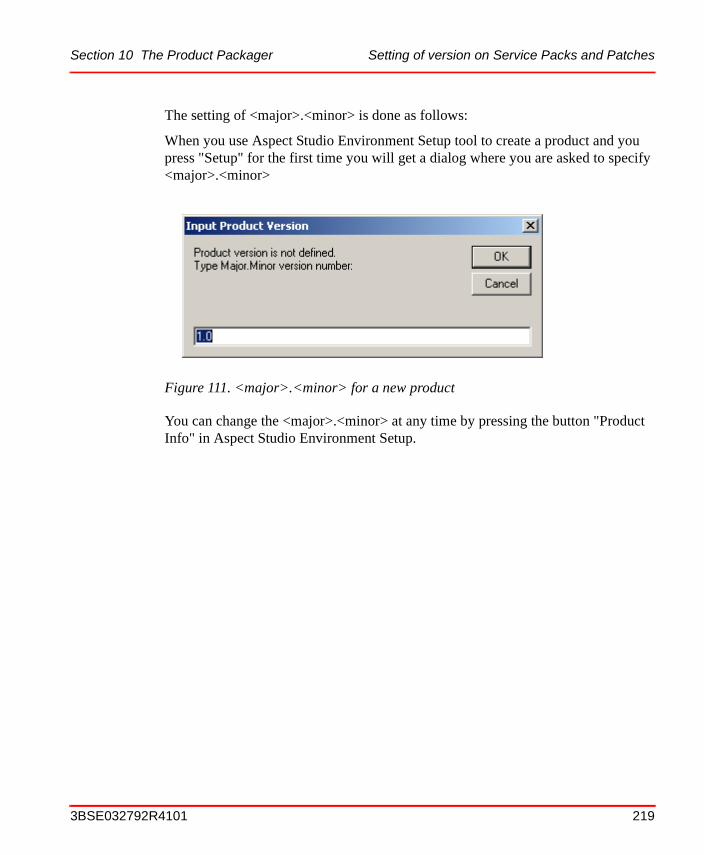
Section 10 The Product Packager Setting of version on Service Packs and Patches
The setting of <major>.<minor> is done as follows:
When you use Aspect Studio Environment Setup tool to create a product and you press "Setup" for the first time you will get a dialog where you are asked to specify <major>.<minor>
You can change the <major>.<minor> at any time by pressing the button "Product Info" in Aspect Studio Environment Setup.
Figure 111. <major>.<minor> for a new product
3BSE032792R4101 219
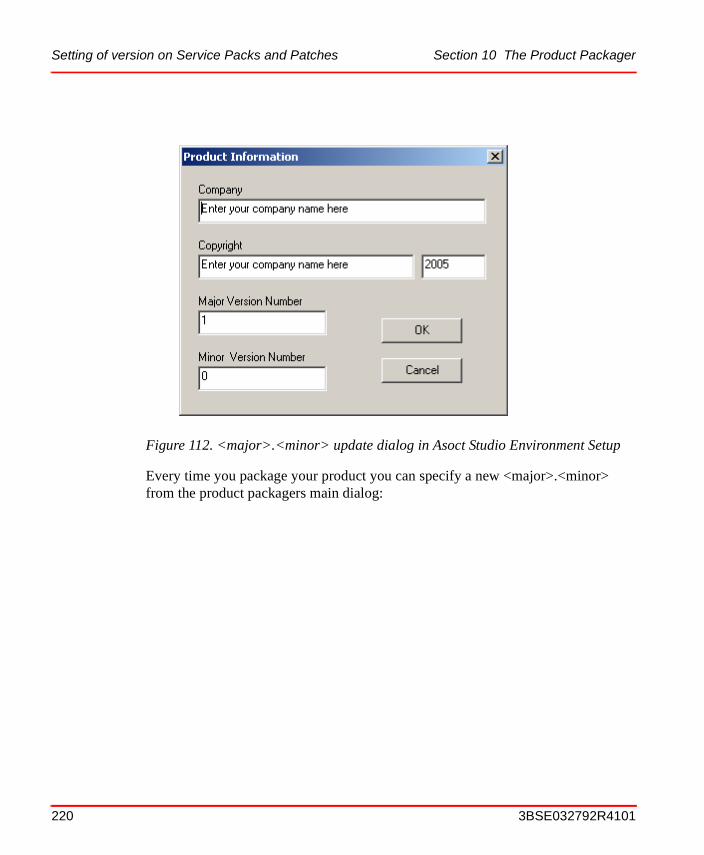
Setting of version on Service Packs and Patches Section 10 The Product Packager
Every time you package your product you can specify a new <major>.<minor> from the product packagers main dialog:
Figure 112. <major>.<minor> update dialog in Asoct Studio Environment Setup
220 3BSE032792R4101
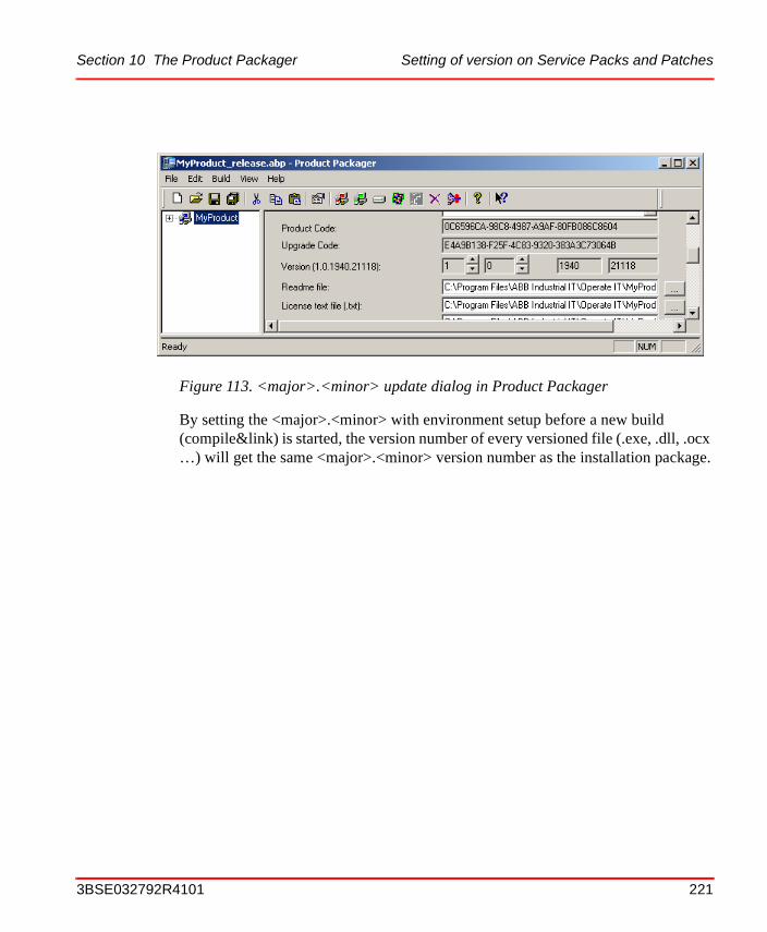
Section 10 The Product Packager Setting of version on Service Packs and Patches
By setting the <major>.<minor> with environment setup before a new build (compile&link) is started, the version number of every versioned file (.exe, .dll, .ocx …) will get the same <major>.<minor> version number as the installation package.
Figure 113. <major>.<minor> update dialog in Product Packager
3BSE032792R4101 221
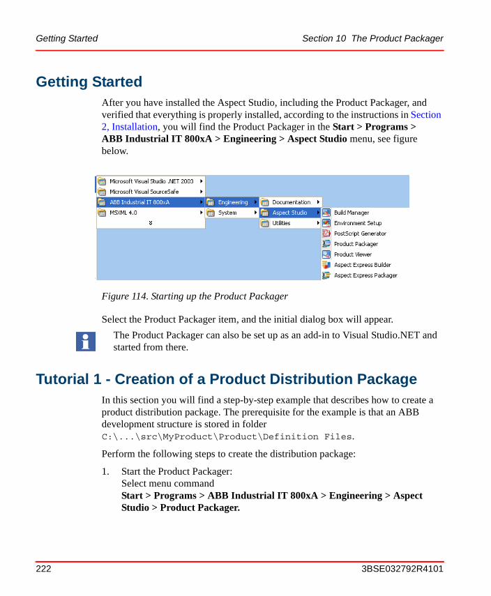
Getting Started Section 10 The Product Packager
Getting StartedAfter you have installed the Aspect Studio, including the Product Packager, and verified that everything is properly installed, according to the instructions in Section 2, Installation, you will find the Product Packager in the Start > Programs > ABB Industrial IT 800xA > Engineering > Aspect Studio menu, see figure below.
Select the Product Packager item, and the initial dialog box will appear.
Tutorial 1 - Creation of a Product Distribution PackageIn this section you will find a step-by-step example that describes how to create a product distribution package. The prerequisite for the example is that an ABB development structure is stored in folder C:\...\src\MyProduct\Product\Definition Files.
Perform the following steps to create the distribution package:
1. Start the Product Packager:Select menu commandStart > Programs > ABB Industrial IT 800xA > Engineering > Aspect Studio > Product Packager.
Figure 114. Starting up the Product Packager
The Product Packager can also be set up as an add-in to Visual Studio.NET and started from there.
222 3BSE032792R4101
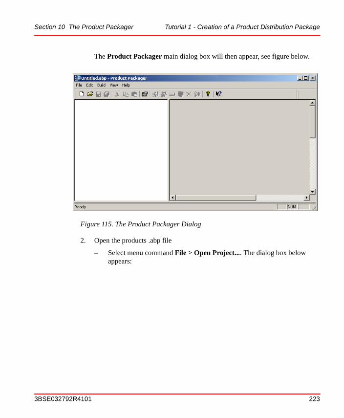
Section 10 The Product Packager Tutorial 1 - Creation of a Product Distribution Package
The Product Packager main dialog box will then appear, see figure below.
2. Open the products .abp file
– Select menu command File > Open Project.... The dialog box below appears:
Figure 115. The Product Packager Dialog
3BSE032792R4101 223
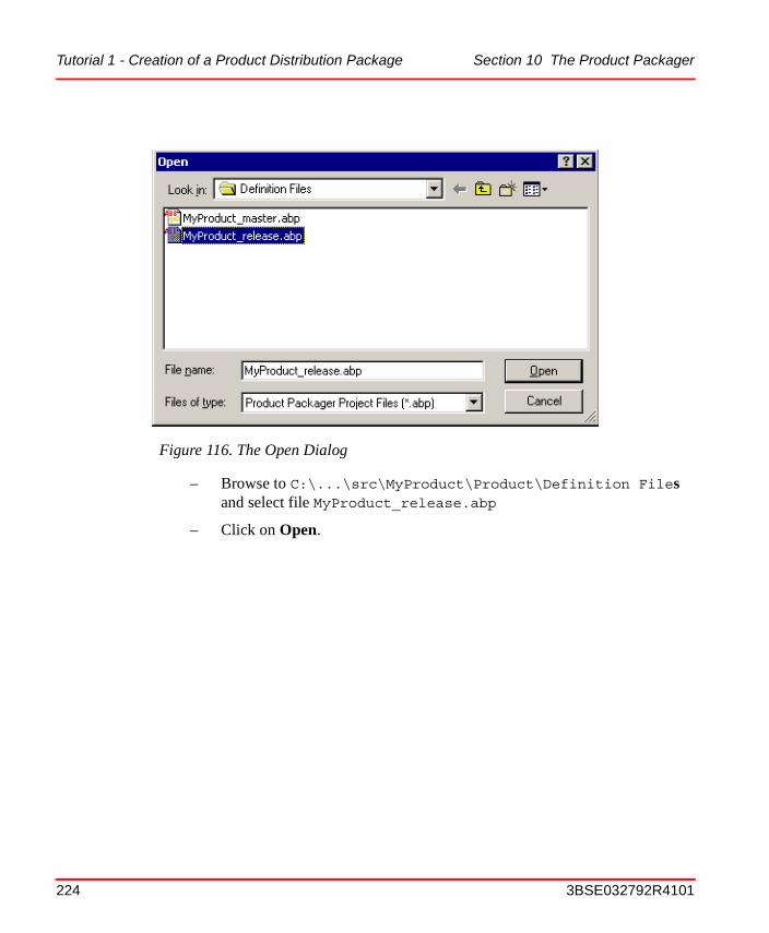
Tutorial 1 - Creation of a Product Distribution Package Section 10 The Product Packager
– Browse to C:\...\src\MyProduct\Product\Definition Files and select file MyProduct_release.abp
– Click on Open.
Figure 116. The Open Dialog
224 3BSE032792R4101
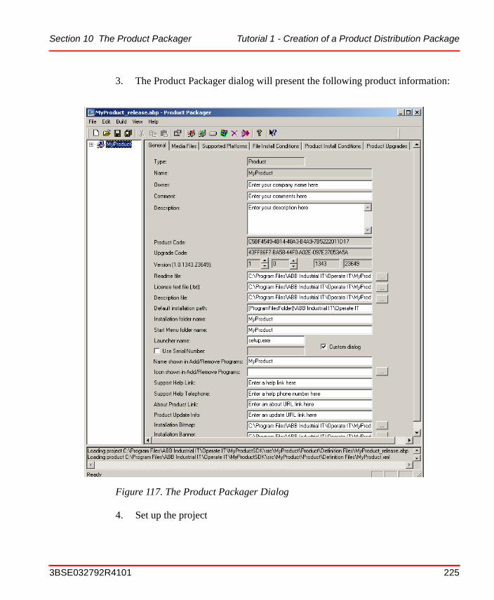
Section 10 The Product Packager Tutorial 1 - Creation of a Product Distribution Package
3. The Product Packager dialog will present the following product information:
4. Set up the project
Figure 117. The Product Packager Dialog
3BSE032792R4101 225
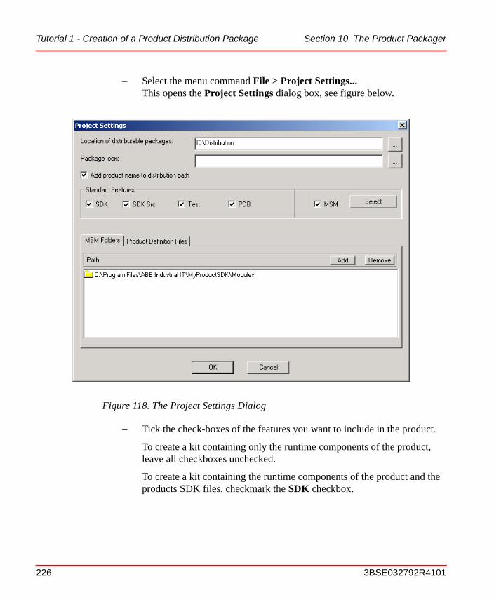
Tutorial 1 - Creation of a Product Distribution Package Section 10 The Product Packager
– Select the menu command File > Project Settings...This opens the Project Settings dialog box, see figure below.
– Tick the check-boxes of the features you want to include in the product.
To create a kit containing only the runtime components of the product, leave all checkboxes unchecked.
To create a kit containing the runtime components of the product and the products SDK files, checkmark the SDK checkbox.
Figure 118. The Project Settings Dialog
226 3BSE032792R4101
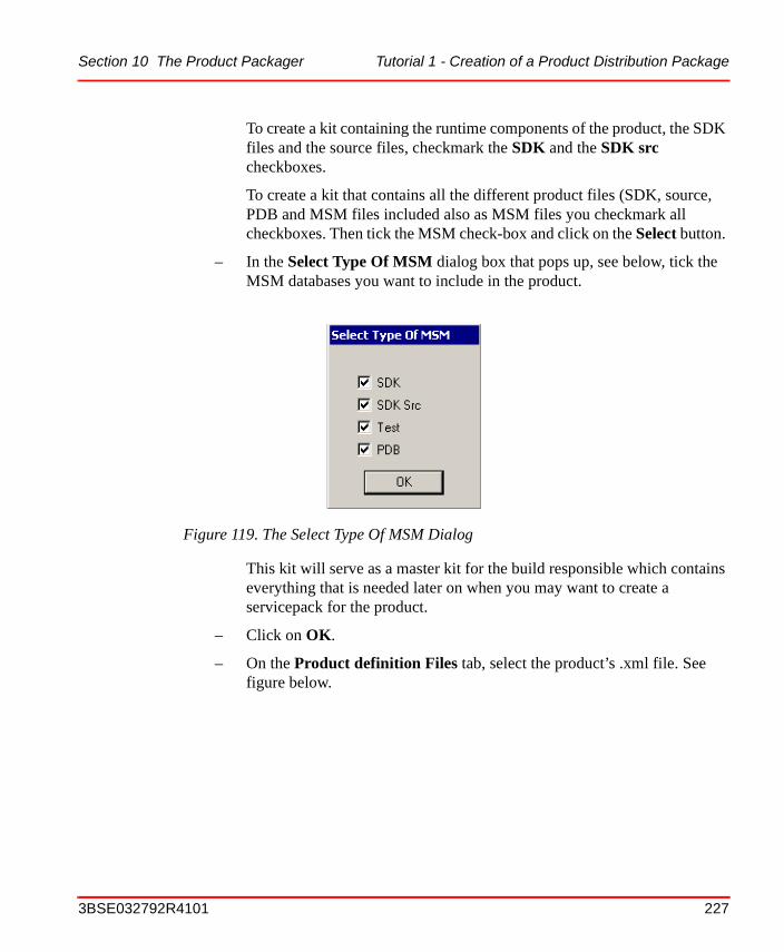
Section 10 The Product Packager Tutorial 1 - Creation of a Product Distribution Package
To create a kit containing the runtime components of the product, the SDK files and the source files, checkmark the SDK and the SDK src checkboxes.
To create a kit that contains all the different product files (SDK, source, PDB and MSM files included also as MSM files you checkmark all checkboxes. Then tick the MSM check-box and click on the Select button.
– In the Select Type Of MSM dialog box that pops up, see below, tick the MSM databases you want to include in the product.
This kit will serve as a master kit for the build responsible which contains everything that is needed later on when you may want to create a servicepack for the product.
– Click on OK.
– On the Product definition Files tab, select the product’s .xml file. See figure below.
Figure 119. The Select Type Of MSM Dialog
3BSE032792R4101 227
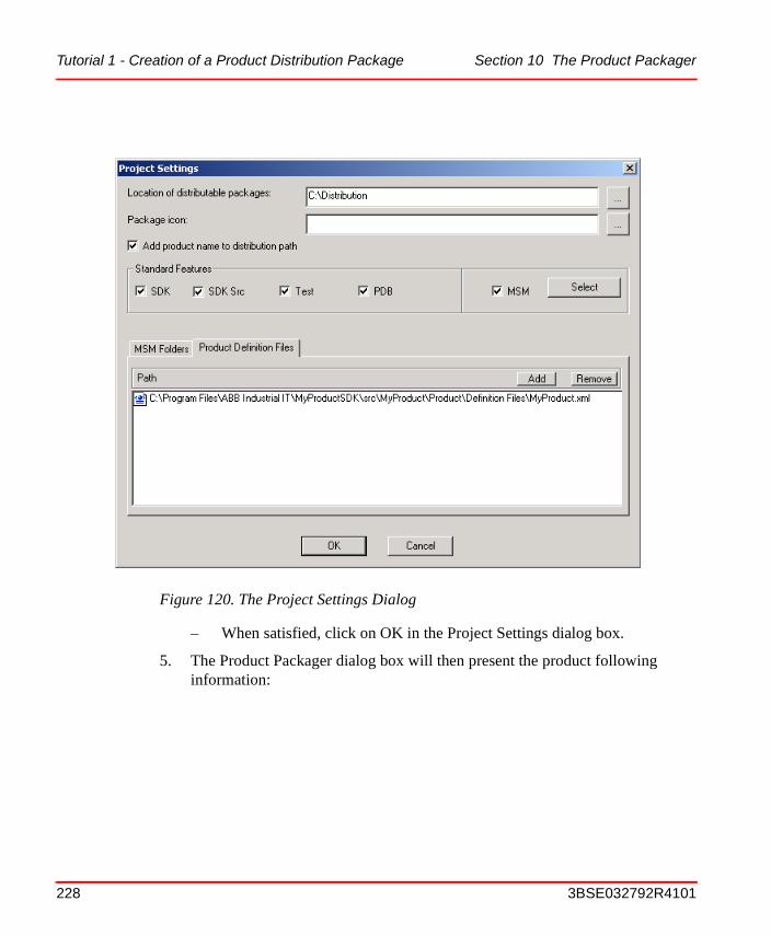
Tutorial 1 - Creation of a Product Distribution Package Section 10 The Product Packager
– When satisfied, click on OK in the Project Settings dialog box.
5. The Product Packager dialog box will then present the product following information:
Figure 120. The Project Settings Dialog
228 3BSE032792R4101

Section 10 The Product Packager Tutorial 1 - Creation of a Product Distribution Package
In the tree view you will see all functions (MSMs) until now have been added to the product structure. This is illustrated with the "MyProduct_Product" branch in the figure. For an instruction on how to add new functions, see Step 6 below.
Figure 121. The Product Packager Dialog
3BSE032792R4101 229
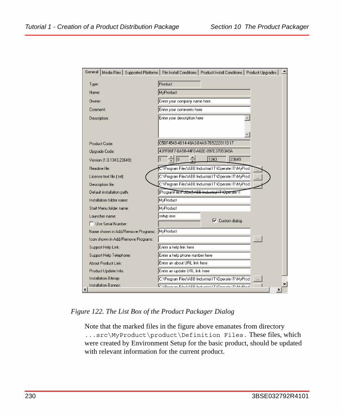
Tutorial 1 - Creation of a Product Distribution Package Section 10 The Product Packager
Note that the marked files in the figure above emanates from directory ...src\MyProduct\product\Definition Files. These files, which were created by Environment Setup for the basic product, should be updated with relevant information for the current product.
Figure 122. The List Box of the Product Packager Dialog
230 3BSE032792R4101
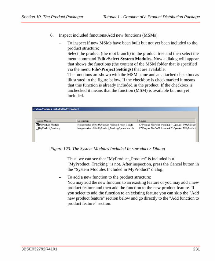
Section 10 The Product Packager Tutorial 1 - Creation of a Product Distribution Package
6. Inspect included functions/Add new functions (MSMs)
– To inspect if new MSMs have been built but not yet been included to the product structure:Select the product (the root branch) in the product tree and then select the menu command Edit>Select System Modules. Now a dialog will appear that shows the functions (the content of the MSM folder that is specified via the menu File>Project Settings) that are available.The functions are shown with the MSM name and an attached checkbox as illustrated in the figure below. If the checkbox is checkmarked it means that this function is already included in the product. If the checkbox is unchecked it means that the function (MSM) is available but not yet included.
Thus, we can see that "MyProduct_Product" is included but "MyProduct_Tracking" is not. After inspection, press the Cancel button in the "System Modules Included in MyProduct" dialog.
– To add a new function to the product structure:You may add the new function to an existing feature or you may add a new product feature and then add the function to the new product feature. If you select to add the function to an existing feature you can skip the "Add new product feature" section below and go directly to the "Add function to product feature" section.
Figure 123. The System Modules Included In <product> Dialog
3BSE032792R4101 231

Tutorial 1 - Creation of a Product Distribution Package Section 10 The Product Packager
Add new product featureSelect the product (the root branch) in the product tree or select the parent feature if you want to create a sub-feature. Then select the menu command Edit>New Feature... Give a name and owner to the new feature dialog that pops up.
Press the OK button and the new feature will be added to the product tree.
Add function to product featureSelect the feature in the product tree that you want the new function (MSM) to be added to. Then select the menu command Edit>Select System Modules. Now you can checkmark the new function "MyProduct_Tracking" and when you press the OK button the new function will be added to the product feature as illustrated below.
Figure 124. New Feature Dialog
Figure 125. MyProduct_Tracking was added to the Liquid Flow Product Feature
232 3BSE032792R4101
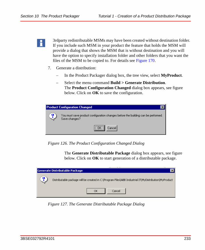
Section 10 The Product Packager Tutorial 1 - Creation of a Product Distribution Package
7. Generate a distribution:
– In the Product Packager dialog box, the tree view, select MyProduct.
– Select the menu command Build > Generate Distribution.The Product Configuration Changed dialog box appears, see figure below. Click on OK to save the configuration.
The Generate Distributable Package dialog box appears, see figure below. Click on OK to start generation of a distributable package.
3rdparty redistributable MSMs may have been created without destination folder. If you include such MSM in your product the feature that holds the MSM will provide a dialog that shows the MSM that is without destination and you will have the option to specify installation folder and other folders that you want the files of the MSM to be copied to. For details see Figure 170.
Figure 126. The Product Configuration Changed Dialog
Figure 127. The Generate Distributable Package Dialog
3BSE032792R4101 233
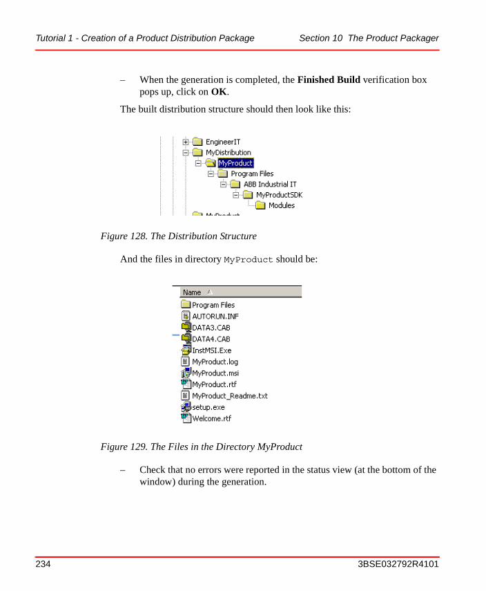
Tutorial 1 - Creation of a Product Distribution Package Section 10 The Product Packager
– When the generation is completed, the Finished Build verification box pops up, click on OK.
The built distribution structure should then look like this:
And the files in directory MyProduct should be:
– Check that no errors were reported in the status view (at the bottom of the window) during the generation.
Figure 128. The Distribution Structure
Figure 129. The Files in the Directory MyProduct
234 3BSE032792R4101
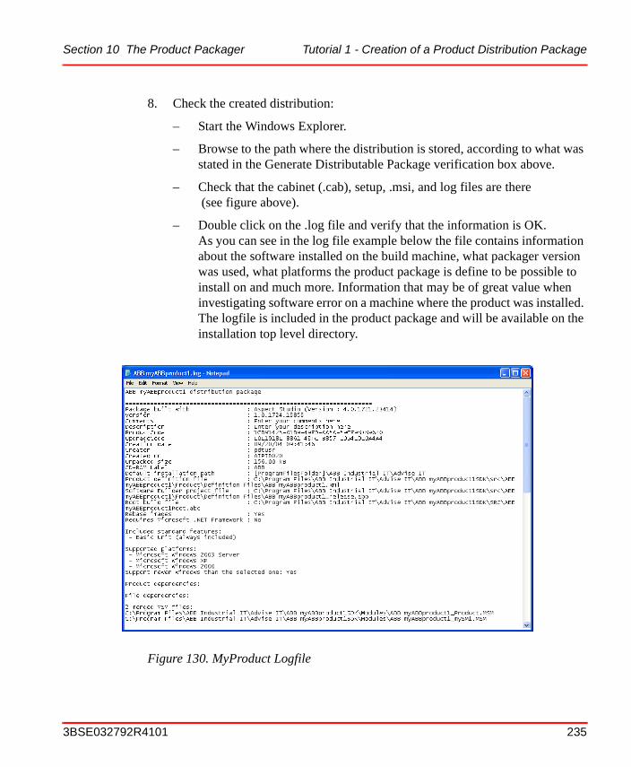
Section 10 The Product Packager Tutorial 1 - Creation of a Product Distribution Package
8. Check the created distribution:
– Start the Windows Explorer.
– Browse to the path where the distribution is stored, according to what was stated in the Generate Distributable Package verification box above.
– Check that the cabinet (.cab), setup, .msi, and log files are there (see figure above).
– Double click on the .log file and verify that the information is OK. As you can see in the log file example below the file contains information about the software installed on the build machine, what packager version was used, what platforms the product package is define to be possible to install on and much more. Information that may be of great value when investigating software error on a machine where the product was installed. The logfile is included in the product package and will be available on the installation top level directory.
Figure 130. MyProduct Logfile
3BSE032792R4101 235

Tutorial 1 - Creation of a Product Distribution Package Section 10 The Product Packager
9. Save the Product Packager settings for later use:
– Select the menu command File > Save Project As...The Save As dialog box appears, see figure below.
Browse to the MyProduct folder.
– Enter file name MyProduct_release.abp, or select it if it’s already there.
– Click on Save.If the file already exists, a confirmation box appears that asks whether you want to overwrite the file or not.
10. Store the distribution on a suitable media (normally a CD-ROM) or on an Internet web site.
Figure 131. The Save As Dialog
236 3BSE032792R4101
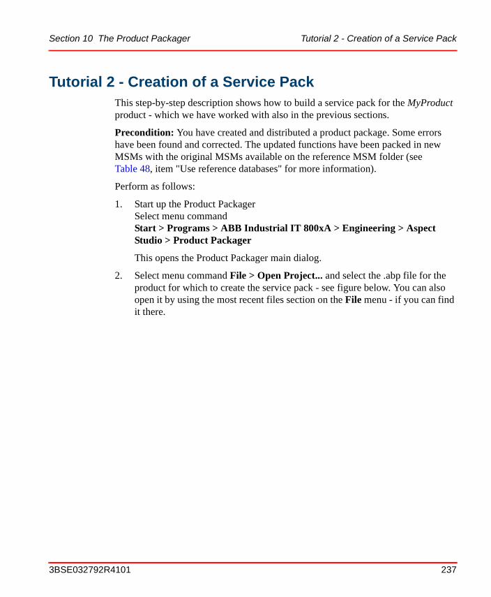
Section 10 The Product Packager Tutorial 2 - Creation of a Service Pack
Tutorial 2 - Creation of a Service PackThis step-by-step description shows how to build a service pack for the MyProduct product - which we have worked with also in the previous sections.
Precondition: You have created and distributed a product package. Some errors have been found and corrected. The updated functions have been packed in new MSMs with the original MSMs available on the reference MSM folder (see Table 48, item "Use reference databases" for more information).
Perform as follows:
1. Start up the Product PackagerSelect menu command Start > Programs > ABB Industrial IT 800xA > Engineering > Aspect Studio > Product Packager
This opens the Product Packager main dialog.
2. Select menu command File > Open Project... and select the .abp file for the product for which to create the service pack - see figure below. You can also open it by using the most recent files section on the File menu - if you can find it there.
3BSE032792R4101 237
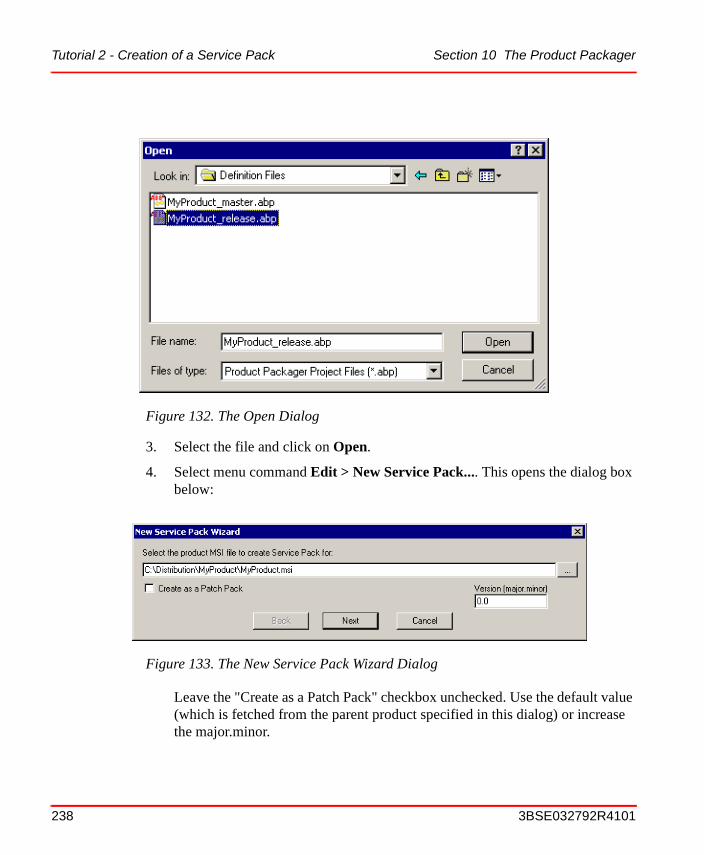
Tutorial 2 - Creation of a Service Pack Section 10 The Product Packager
3. Select the file and click on Open.
4. Select menu command Edit > New Service Pack.... This opens the dialog box below:
Leave the "Create as a Patch Pack" checkbox unchecked. Use the default value (which is fetched from the parent product specified in this dialog) or increase the major.minor.
Figure 132. The Open Dialog
Figure 133. The New Service Pack Wizard Dialog
238 3BSE032792R4101
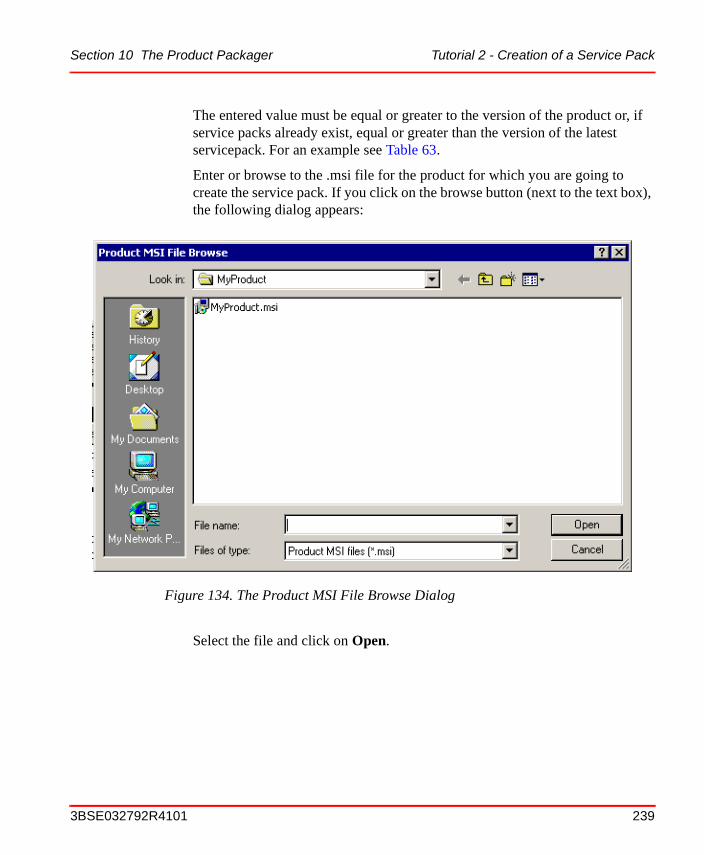
Section 10 The Product Packager Tutorial 2 - Creation of a Service Pack
The entered value must be equal or greater to the version of the product or, if service packs already exist, equal or greater than the version of the latest servicepack. For an example see Table 63.
Enter or browse to the .msi file for the product for which you are going to create the service pack. If you click on the browse button (next to the text box), the following dialog appears:
Select the file and click on Open.
Figure 134. The Product MSI File Browse Dialog
3BSE032792R4101 239

Tutorial 2 - Creation of a Service Pack Section 10 The Product Packager
5. The Name and Owner dialog box appears.Then the following dialog box appears:
The Name text box will be automatically filled in, you can however change the name if you want. In the Owner text box, fill in your name. Then click on Next. If you want to change what you entered on the previous dialog(s), click on Back.
6. When you click on Next, you have to specify the destination path for the Definition file. the following dialog box appears:
Figure 135. Set Name and Owner of Service Pack
Figure 136. Select Destination for the Service Pack Destination File
240 3BSE032792R4101
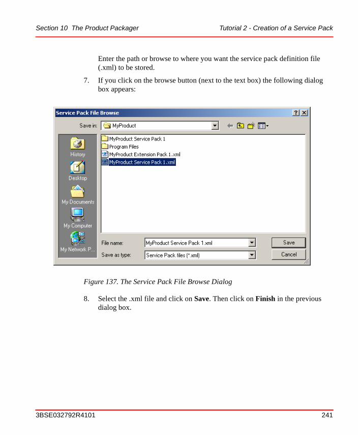
Section 10 The Product Packager Tutorial 2 - Creation of a Service Pack
Enter the path or browse to where you want the service pack definition file (.xml) to be stored.
7. If you click on the browse button (next to the text box) the following dialog box appears:
8. Select the .xml file and click on Save. Then click on Finish in the previous dialog box.
Figure 137. The Service Pack File Browse Dialog
3BSE032792R4101 241
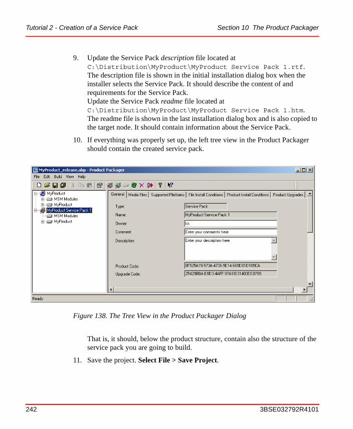
Tutorial 2 - Creation of a Service Pack Section 10 The Product Packager
9. Update the Service Pack description file located at C:\Distribution\MyProduct\MyProduct Service Pack 1.rtf. The description file is shown in the initial installation dialog box when the installer selects the Service Pack. It should describe the content of and requirements for the Service Pack.Update the Service Pack readme file located at C:\Distribution\MyProduct\MyProduct Service Pack 1.htm. The readme file is shown in the last installation dialog box and is also copied to the target node. It should contain information about the Service Pack.
10. If everything was properly set up, the left tree view in the Product Packager should contain the created service pack.
That is, it should, below the product structure, contain also the structure of the service pack you are going to build.
11. Save the project. Select File > Save Project.
Figure 138. The Tree View in the Product Packager Dialog
242 3BSE032792R4101
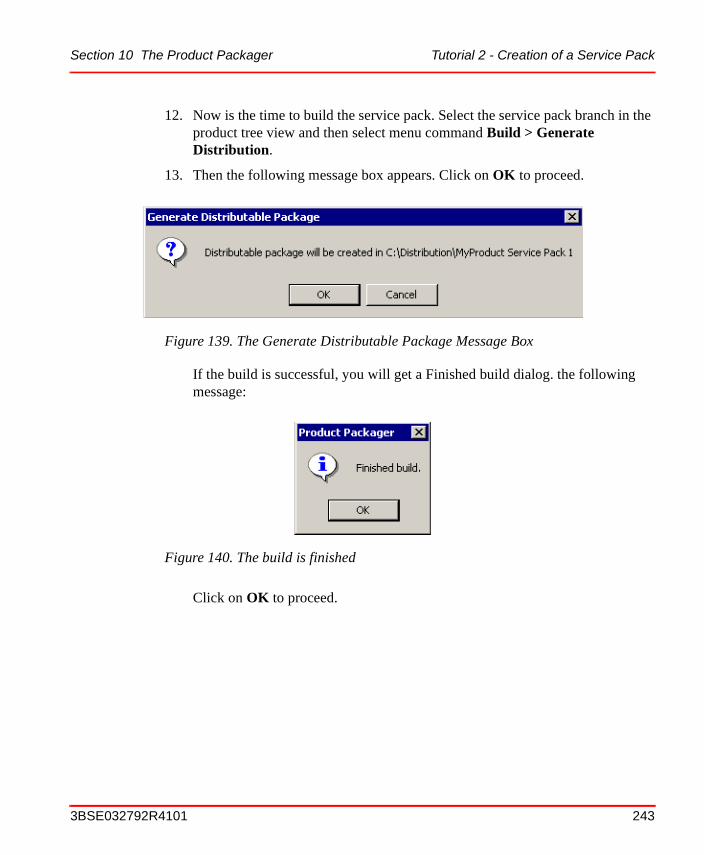
Section 10 The Product Packager Tutorial 2 - Creation of a Service Pack
12. Now is the time to build the service pack. Select the service pack branch in the product tree view and then select menu command Build > Generate Distribution.
13. Then the following message box appears. Click on OK to proceed.
If the build is successful, you will get a Finished build dialog. the following message:
Click on OK to proceed.
Figure 139. The Generate Distributable Package Message Box
Figure 140. The build is finished
3BSE032792R4101 243

Tutorial 2 - Creation of a Service Pack Section 10 The Product Packager
14. Select File > Exit. If you didn’t save the project earlier you will get a Save project question.
To avoid this message, select File > Save Project before File > Exit.
If you now, after having finished the service pack build, open Windows Explorer you should see the following folder and files created for your service pack.
Open the .log file to verify that no severe errors have occurred.
Figure 141. Click Yes to save changes
Figure 142. The Windows Explorer
244 3BSE032792R4101
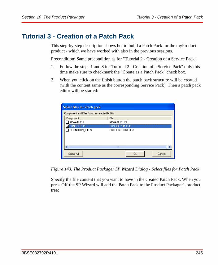
Section 10 The Product Packager Tutorial 3 - Creation of a Patch Pack
Tutorial 3 - Creation of a Patch PackThis step-by-step description shows hot to build a Patch Pack for the myProduct product - which we have worked with also in the previous sessions.
Precondition: Same precondition as for "Tutorial 2 - Creation of a Service Pack".
1. Follow the steps 1 and 8 in "Tutorial 2 - Creation of a Service Pack" only this time make sure to checkmark the "Create as a Patch Pack" check box.
2. When you click on the finish button the patch pack structure will be created (with the content same as the corresponding Service Pack). Then a patch pack editor will be started:
Specify the file content that you want to have in the created Patch Pack. When you press OK the SP Wizard will add the Patch Pack to the Product Packager's product tree:
Figure 143. The Product Packager SP Wizard Dialog - Select files for Patch Pack
3BSE032792R4101 245
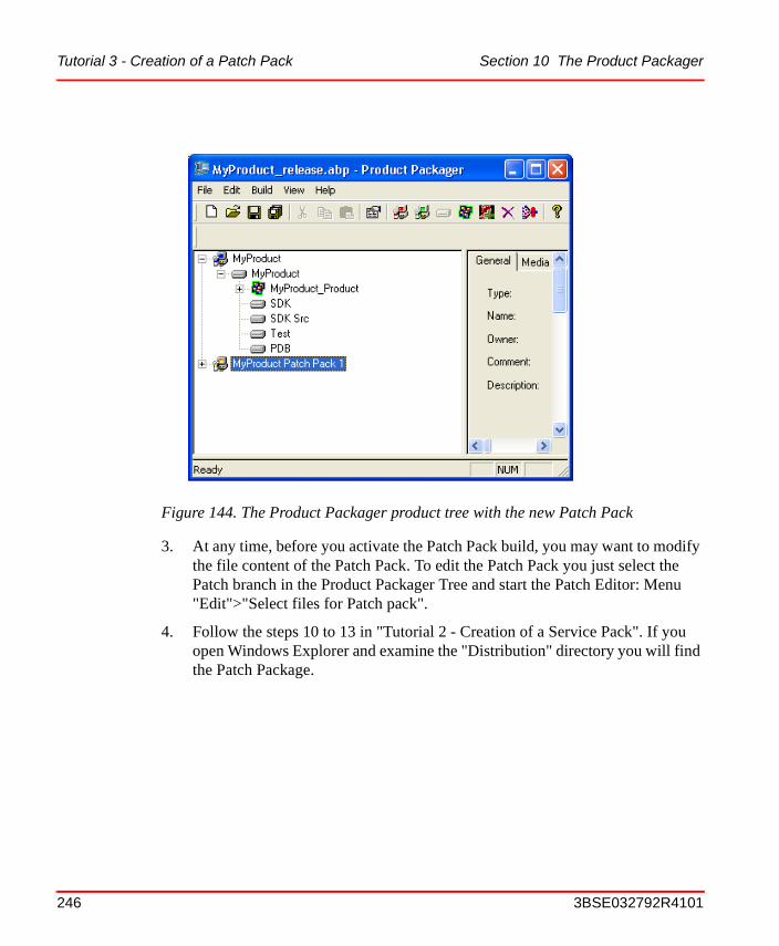
Tutorial 3 - Creation of a Patch Pack Section 10 The Product Packager
3. At any time, before you activate the Patch Pack build, you may want to modify
the file content of the Patch Pack. To edit the Patch Pack you just select the Patch branch in the Product Packager Tree and start the Patch Editor: Menu "Edit">"Select files for Patch pack".
4. Follow the steps 10 to 13 in "Tutorial 2 - Creation of a Service Pack". If you open Windows Explorer and examine the "Distribution" directory you will find the Patch Package.
Figure 144. The Product Packager product tree with the new Patch Pack
246 3BSE032792R4101
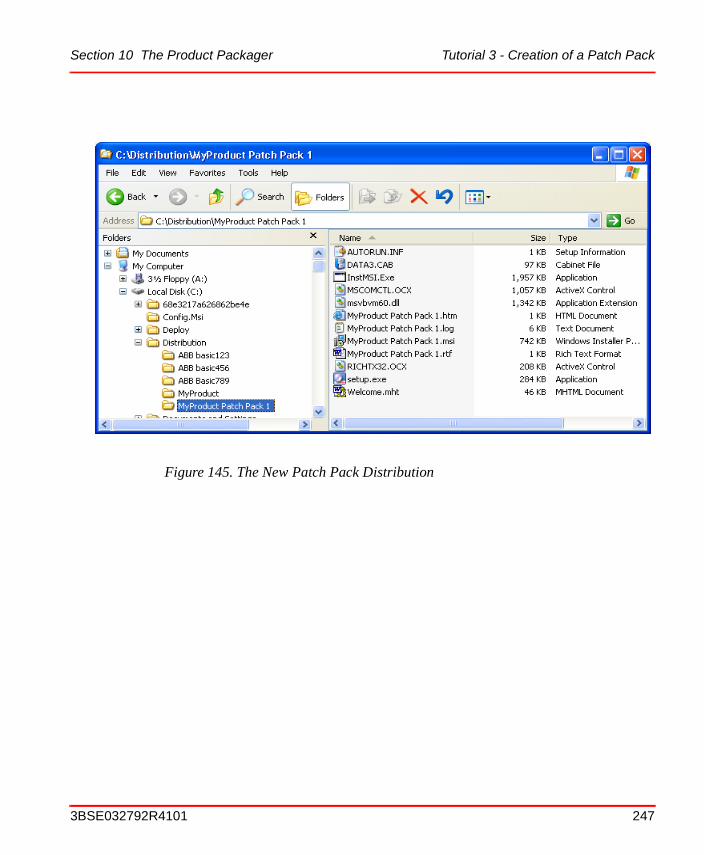
Section 10 The Product Packager Tutorial 3 - Creation of a Patch Pack
Figure 145. The New Patch Pack Distribution
3BSE032792R4101 247
Tutorial 4 - Creation of an Extension Pack Section 10 The Product Packager
Tutorial 4 - Creation of an Extension PackThis step-by-step description shows how to build an extension pack for the MyProduct product - which we have worked with also in the previous sections.
Precondition:
You have created and distributed a product package. Now you want to create and distribute additional functions and there are mainly two different cases when you want to do this:
Case 1:
You want to package development items like the products software development kit (SDK), the products source code (SDK src), the products test tools (TEST) or the products program database files (PDB) to a installable package that is possible to install as an add-on on the computers that has the original product installed (the runtime).
Case 2:
You want to package a new end-user function (a function that was not included in the original package e.g. light sensor control s/w) to a installable package that is possible to install as an add-on on the computers that has the original product installed (the runtime).
In both cases you must have the add-on functionality available on the products MSM folder.
Perform as follows:
1. Start up the Product PackagerSelect menu command Start > Programs > ABB Industrial IT 800xA > Engineering > Aspect Studio > Product Packager
This opens the Product Packager main dialog.
Remember that the development items listed below also can, if you prefer to have them in the same product package as the runtime components, be packaged as product features. See Tutorial 1 - Creation of a Product Distribution Package on page 222.
248 3BSE032792R4101
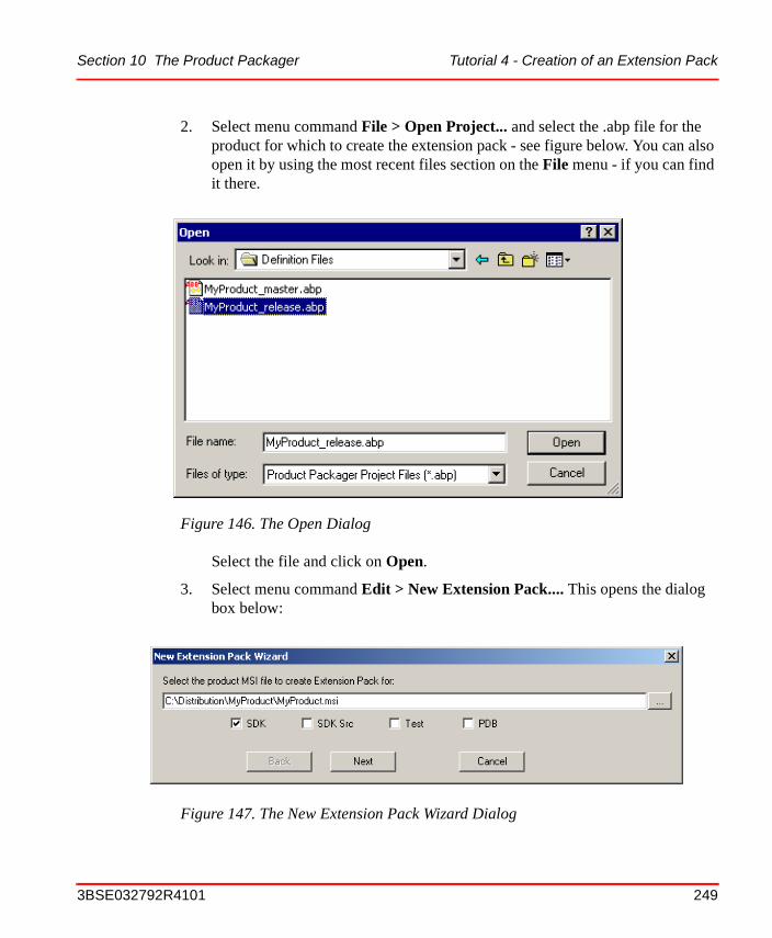
Section 10 The Product Packager Tutorial 4 - Creation of an Extension Pack
2. Select menu command File > Open Project... and select the .abp file for the product for which to create the extension pack - see figure below. You can also open it by using the most recent files section on the File menu - if you can find it there.
Select the file and click on Open.
3. Select menu command Edit > New Extension Pack.... This opens the dialog box below:
Figure 146. The Open Dialog
Figure 147. The New Extension Pack Wizard Dialog
3BSE032792R4101 249
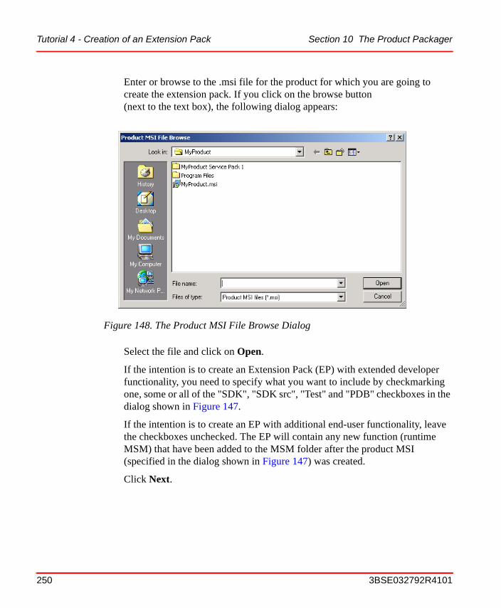
Tutorial 4 - Creation of an Extension Pack Section 10 The Product Packager
Enter or browse to the .msi file for the product for which you are going to create the extension pack. If you click on the browse button (next to the text box), the following dialog appears:
Select the file and click on Open.
If the intention is to create an Extension Pack (EP) with extended developer functionality, you need to specify what you want to include by checkmarking one, some or all of the "SDK", "SDK src", "Test" and "PDB" checkboxes in the dialog shown in Figure 147.
If the intention is to create an EP with additional end-user functionality, leave the checkboxes unchecked. The EP will contain any new function (runtime MSM) that have been added to the MSM folder after the product MSI (specified in the dialog shown in Figure 147) was created.
Click Next.
Figure 148. The Product MSI File Browse Dialog
250 3BSE032792R4101
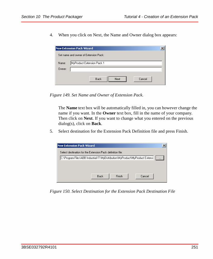
Section 10 The Product Packager Tutorial 4 - Creation of an Extension Pack
4. When you click on Next, the Name and Owner dialog box appears:
The Name text box will be automatically filled in, you can however change the name if you want. In the Owner text box, fill in the name of your company. Then click on Next. If you want to change what you entered on the previous dialog(s), click on Back.
5. Select destination for the Extension Pack Definition file and press Finish.
Figure 149. Set Name and Owner of Extension Pack.
Figure 150. Select Destination for the Extension Pack Destination File
3BSE032792R4101 251
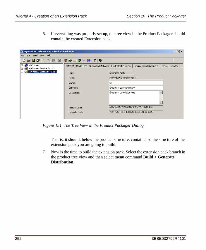
Tutorial 4 - Creation of an Extension Pack Section 10 The Product Packager
6. If everything was properly set up, the tree view in the Product Packager should contain the created Extension pack.
That is, it should, below the product structure, contain also the structure of the extension pack you are going to build.
7. Now is the time to build the extension pack. Select the extension pack branch in the product tree view and then select menu command Build > Generate Distribution.
Figure 151. The Tree View in the Product Packager Dialog
252 3BSE032792R4101

Section 10 The Product Packager Tutorial 4 - Creation of an Extension Pack
8. Then a Generate Distributable package dialog the following message box appears. Click on OK to proceed.
If the build is successful, you will get a Finished build dialog
9. Click on OK to proceed.
10. If you now select File > Exit, you will get a Save project question:
To avoid this message, select File > Save Project before File > Exit.
Figure 152. The Generate Distributable Package Message Box
Figure 153. The Build is Finished
Figure 154. Decide if you will save changes
3BSE032792R4101 253
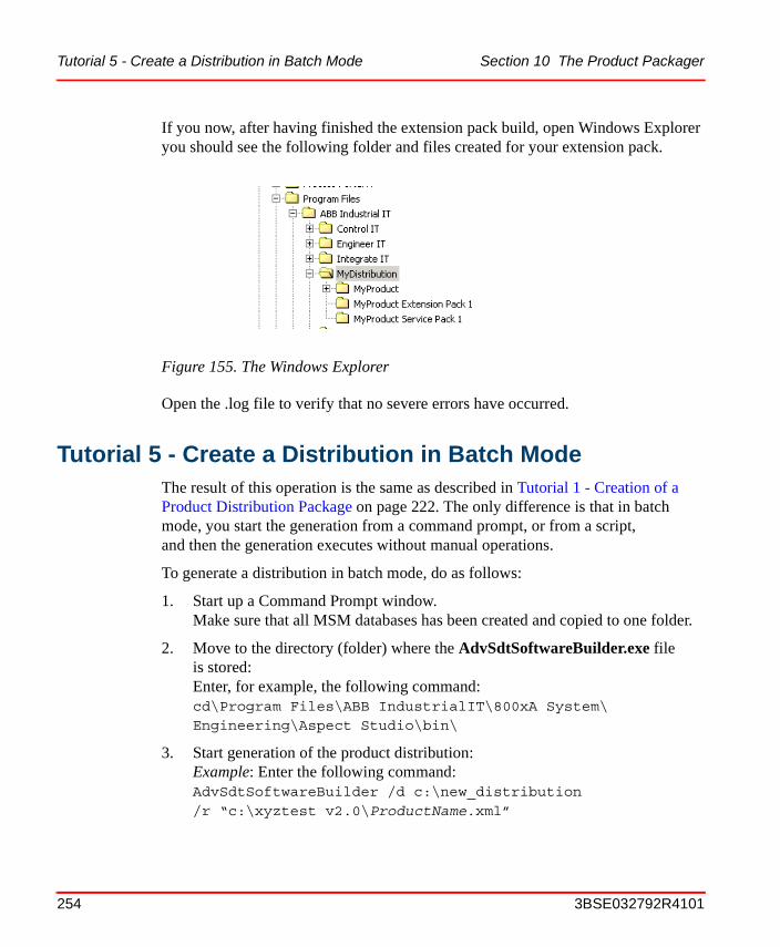
Tutorial 5 - Create a Distribution in Batch Mode Section 10 The Product Packager
If you now, after having finished the extension pack build, open Windows Explorer you should see the following folder and files created for your extension pack.
Open the .log file to verify that no severe errors have occurred.
Tutorial 5 - Create a Distribution in Batch ModeThe result of this operation is the same as described in Tutorial 1 - Creation of a Product Distribution Package on page 222. The only difference is that in batch mode, you start the generation from a command prompt, or from a script, and then the generation executes without manual operations.
To generate a distribution in batch mode, do as follows:
1. Start up a Command Prompt window.Make sure that all MSM databases has been created and copied to one folder.
2. Move to the directory (folder) where the AdvSdtSoftwareBuilder.exe file is stored:Enter, for example, the following command: cd\Program Files\ABB IndustrialIT\800xA System\Engineering\Aspect Studio\bin\
3. Start generation of the product distribution:Example: Enter the following command:AdvSdtSoftwareBuilder /d c:\new_distribution /r “c:\xyztest v2.0\ProductName.xml”
Figure 155. The Windows Explorer
254 3BSE032792R4101

Section 10 The Product Packager Procedures
/m c:\distribution\Modules /c NWhere the parameter following after- /d is the destination folder, that is where the distribution will be stored,- /r is the path to the product .xml - /m is the path to the MSM folder where all MSM databases for the product is stored, and- /c informs AdvSdtSoftwareBuilder whether the destination folder shall be cleared or not before storing the new distribution.
Use quotes (“) when there is one or more spaces in a path description. If not, the program will interpret the space(s) as a delimiter for a new parameter.
To get help about the distribution create command, enter commandAdvSdtSoftwareBuilder ? A list that explains the /d, /r,/m,and /c parameters will the be displayed.
4. Verify the generation of the product distribution:
– Start the Windows 2000 Explorer
– Browse to the C:\Temp folder.
– Double click on the AdvSdtSoftwareBuilder.log file icon.
– A text file window appears, telling you about the outcome of the product distribution generation.
ProceduresIn this section you will find the recommended operating procedures for the different features included in the Product Packager. The procedures describe all the steps required, but not necessary all details about all the operations required in each step. To learn more about that, see Tutorial 1 - Creation of a Product Distribution Package on page 222, and User Interfaces on page 268.
The content of each System Module (including its components) is defined in Windows Installer MSM databases. The MSM databases can either be created with the AutoBuild tool, or with the AdvSdtMSMBuilder command.
3BSE032792R4101 255
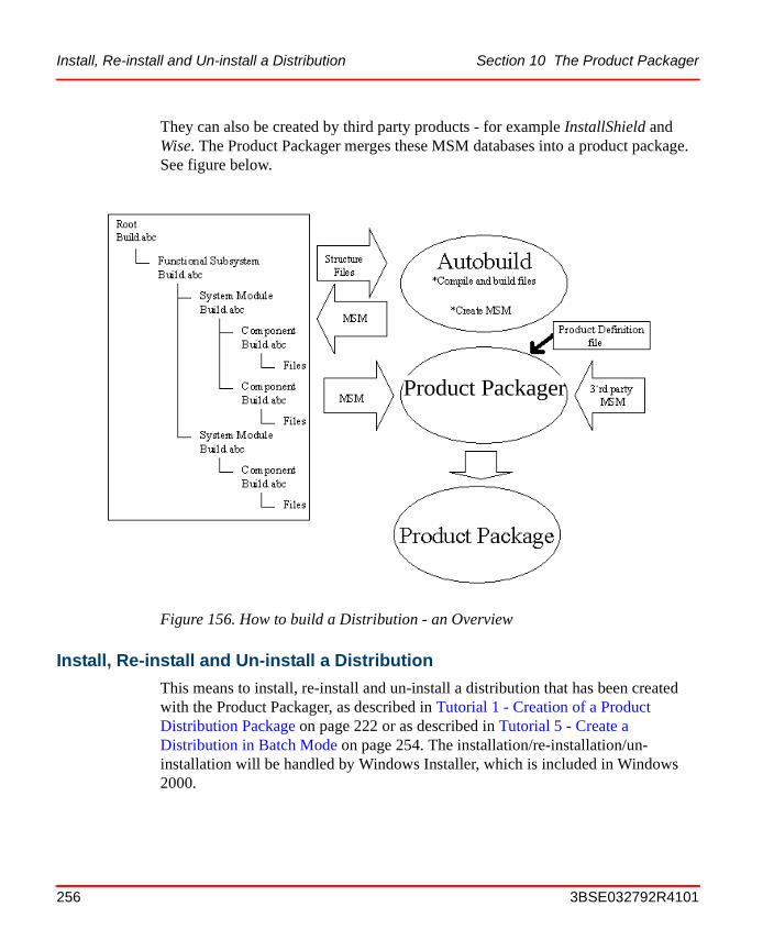
Install, Re-install and Un-install a Distribution Section 10 The Product Packager
They can also be created by third party products - for example InstallShield and Wise. The Product Packager merges these MSM databases into a product package. See figure below.
Install, Re-install and Un-install a Distribution
This means to install, re-install and un-install a distribution that has been created with the Product Packager, as described in Tutorial 1 - Creation of a Product Distribution Package on page 222 or as described in Tutorial 5 - Create a Distribution in Batch Mode on page 254. The installation/re-installation/un-installation will be handled by Windows Installer, which is included in Windows 2000.
Figure 156. How to build a Distribution - an Overview
Product Packager
256 3BSE032792R4101
Section 10 The Product Packager Installation through Internet
If you want to install, re-install or un-install a distribution, perform the following steps:
1. To install a product distribution, locate and double click on the Setup.exe icon for the product distribution. To re-install/un-install, open the Add/Remove program icon in the Control Panel. Select the product distribution you want to re-install/un-install, and then click on the Add/Remove button.
2. Follow the instructions in the dialog boxes that follow.You will, for example, be asked whether you want to change, re-install or un-install. Choose the option you want.
Installation through Internet
It is possible to install a product distribution that is accessible through a URL. This can be done by using:
• The command prompt. Select the menu command Start > Run.... Then enter cmd in the dialog that opens.At the prompter in the command window, enter commandmsiexec /i http://server/share/package.msi
3BSE032792R4101 257
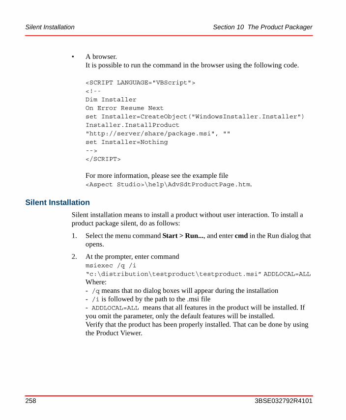
Silent Installation Section 10 The Product Packager
• A browser. It is possible to run the command in the browser using the following code.
<SCRIPT LANGUAGE="VBScript"> <!-- Dim InstallerOn Error Resume Nextset Installer=CreateObject("WindowsInstaller.Installer")Installer.InstallProduct "http://server/share/package.msi", ""set Installer=Nothing--></SCRIPT>
For more information, please see the example file <Aspect Studio>\help\AdvSdtProductPage.htm.
Silent Installation
Silent installation means to install a product without user interaction. To install a product package silent, do as follows:
1. Select the menu command Start > Run..., and enter cmd in the Run dialog that opens.
2. At the prompter, enter commandmsiexec /q /i “c:\distribution\testproduct\testproduct.msi” ADDLOCAL=ALL Where:- /q means that no dialog boxes will appear during the installation- /i is followed by the path to the .msi file- ADDLOCAL=ALL means that all features in the product will be installed. If you omit the parameter, only the default features will be installed.Verify that the product has been properly installed. That can be done by using the Product Viewer.
258 3BSE032792R4101

Section 10 The Product Packager Create a Service Pack
Create a Service Pack
See Tutorial 2 - Creation of a Service Pack on page 237. That section contains sufficient information for how to build a service pack.
Install a Service Pack
How to install a service pack is shown by installing the service pack that was created in Tutorial 2 - Creation of a Service Pack on page 237. Do as follows:
1. Double click on the Setup.exe file stored on the service pack distribution media. This is normally a CD-ROM, but you may also have downloaded the service pack from an Internet site, or you may install it from a server node. This opens the Product Installation dialog:
Figure 157. The Product Installation Dialog
3BSE032792R4101 259
Create an Extension Pack Section 10 The Product Packager
2. Select the product you want to install, MyProduct Service Pack 1 in this case. If you want a log file, tick the Generate Logfile check-box. Then click on Install.
3. To complete the service pack installation - just follow the instructions in the dialog boxes that follows.
Create an Extension Pack
See Tutorial 4 - Creation of an Extension Pack on page 248. That section contains sufficient information for how to build a extension pack.
Install an Extension Pack
How to install an extension pack is shown by installing the extension pack that was created in Tutorial 4 - Creation of an Extension Pack on page 248. Do as follows:
1. Double click on the Setup.exe file stored on the extension pack distribution media. This is normally a CD-ROM, but you may also have downloaded the service pack from an Internet site, or you may install it from a server node. This opens the Product Installation dialog:
260 3BSE032792R4101
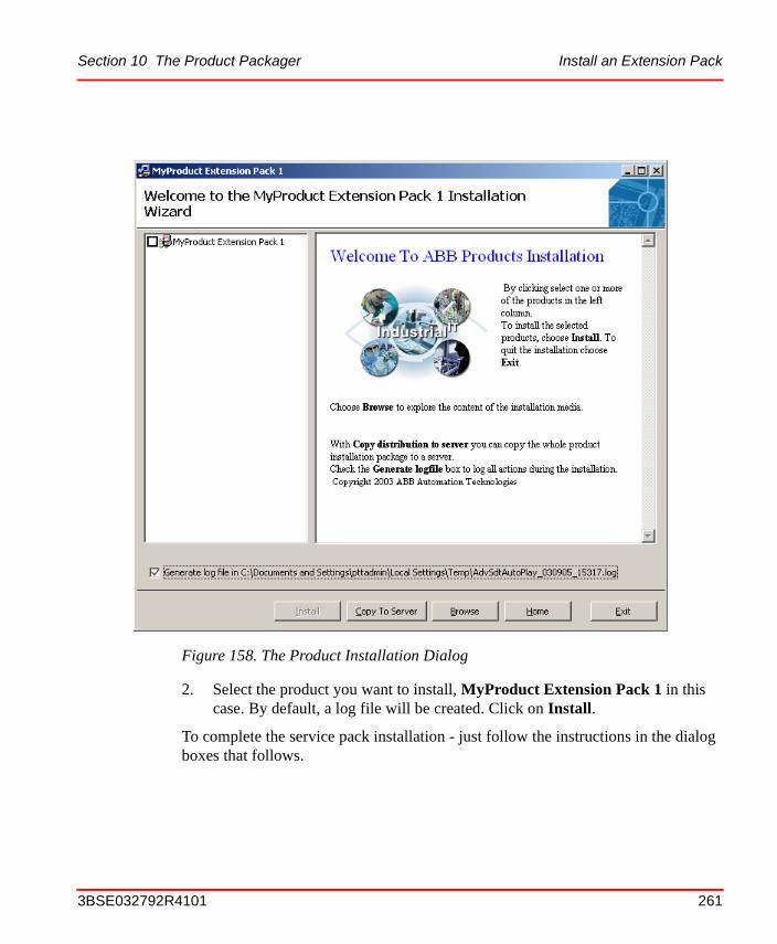
Section 10 The Product Packager Install an Extension Pack
2. Select the product you want to install, MyProduct Extension Pack 1 in this case. By default, a log file will be created. Click on Install.
To complete the service pack installation - just follow the instructions in the dialog boxes that follows.
Figure 158. The Product Installation Dialog
3BSE032792R4101 261
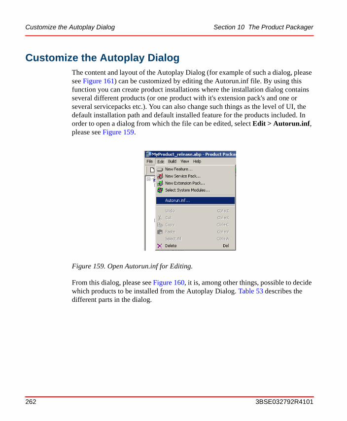
Customize the Autoplay Dialog Section 10 The Product Packager
Customize the Autoplay DialogThe content and layout of the Autoplay Dialog (for example of such a dialog, please see Figure 161) can be customized by editing the Autorun.inf file. By using this function you can create product installations where the installation dialog contains several different products (or one product with it's extension pack's and one or several servicepacks etc.). You can also change such things as the level of UI, the default installation path and default installed feature for the products included. In order to open a dialog from which the file can be edited, select Edit > Autorun.inf, please see Figure 159.
From this dialog, please see Figure 160, it is, among other things, possible to decide which products to be installed from the Autoplay Dialog. Table 53 describes the different parts in the dialog.
Figure 159. Open Autorun.inf for Editing.
262 3BSE032792R4101
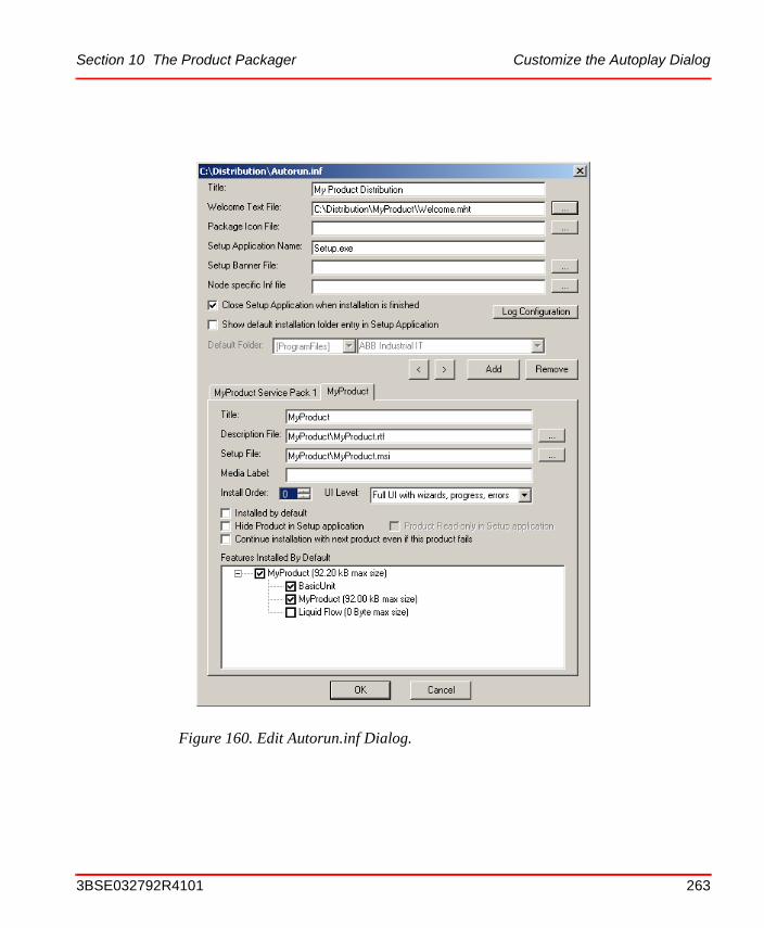
Section 10 The Product Packager Customize the Autoplay Dialog
Figure 160. Edit Autorun.inf Dialog.
3BSE032792R4101 263
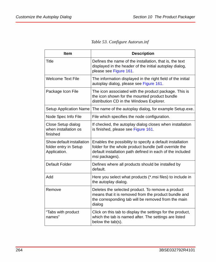
Customize the Autoplay Dialog Section 10 The Product Packager
Table 53. Configure Autorun.inf
Item Description
Title Defines the name of the installation, that is, the text displayed in the header of the initial autoplay dialog, please see Figure 161.
Welcome Text File The information displayed in the right field of the initial autoplay dialog, please see Figure 161.
Package Icon File The icon associated with the product package. This is the icon shown for the mounted product bundle distribution CD in the Windows Explorer.
Setup Application Name The name of the autoplay dialog, for example Setup.exe.
Node Spec Info File File which specifies the node configuration.
Close Setup dialog when installation os finished
If checked, the autoplay dialog closes when installation is finished, please see Figure 161.
Show default installation folder entry in Setup Application.
Enables the possibility to specify a default installation folder for the whole product bundle (will override the default installation path defined in each of the included msi packages).
Default Folder Defines where all products should be installed by default.
Add Here you select what products (*.msi files) to include in the autoplay dialog.
Remove Deletes the selected product. To remove a product means that it is removed from the product bundle and the corresponding tab will be removed from the main dialog
“Tabs with product names”
Click on this tab to display the settings for the product, which the tab is named after. The settings are listed below the tab(s).
264 3BSE032792R4101
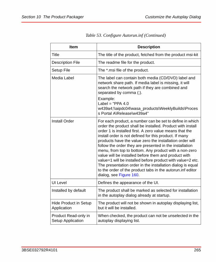
Section 10 The Product Packager Customize the Autoplay Dialog
Title The title of the product, fetched from the product msi-kit
Description File The readme file for the product.
Setup File The *.msi file of the product.
Media Label The label can contain both media (CD/DVD) label and network share path. If media label is missing, it will search the network path if they are combined and separated by comma (;).
Example: Label = "PPA 4.0 w439a4;\\aipdc04\wasa_products\WeeklyBuilds\Process Portal A\Release\w439a4"
Install Order For each product, a number can be set to define in which order the product shall be installed. Product with install order 1 is installed first. A zero value means that the install order is not defined for this product. If many products have the value zero the installation order will follow the order they are presented in the installation menu, from top to bottom. Any product with a non-zero value will be installed before them and product with value=1 will be installed before product with value=2 etc. The presentation order in the installation dialog is equal to the order of the product tabs in the autorun.inf editor dialog, see Figure 160.
UI Level Defines the appearance of the UI.
Installed by default The product shall be marked as selected for installation in the autoplay dialog already at startup.
Hide Product in Setup Application
The product will not be shown in autoplay displaying list, but it will be installed.
Product Read-only in Setup Application
When checked, the product can not be unselected in the autoplay displaying list.
Table 53. Configure Autorun.inf (Continued)
Item Description
3BSE032792R4101 265
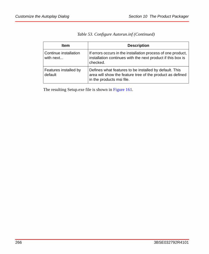
Customize the Autoplay Dialog Section 10 The Product Packager
The resulting Setup.exe file is shown in Figure 161.
Continue installation with next...
If errors occurs in the installation process of one product, installation continues with the next product if this box is checked.
Features installed by default
Defines what features to be installed by default. This area will show the feature tree of the product as defined in the products msi file.
Table 53. Configure Autorun.inf (Continued)
Item Description
266 3BSE032792R4101
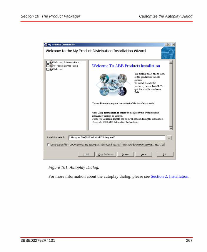
Section 10 The Product Packager Customize the Autoplay Dialog
For more information about the autoplay dialog, please see Section 2, Installation.
Figure 161. Autoplay Dialog.
3BSE032792R4101 267
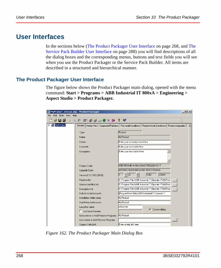
User Interfaces Section 10 The Product Packager
User InterfacesIn the sections below (The Product Packager User Interface on page 268, and The Service Pack Builder User Interface on page 288) you will find descriptions of all the dialog boxes and the corresponding menus, buttons and text fields you will see when you use the Product Packager or the Service Pack Builder. All items are described in a structured and hierarchical manner.
The Product Packager User Interface
The figure below shows the Product Packager main dialog, opened with the menu command: Start > Programs > ABB Industrial IT 800xA > Engineering > Aspect Studio > Product Packager.
Figure 162. The Product Packager Main Dialog Box
268 3BSE032792R4101

Section 10 The Product Packager The Product Packager User Interface
Table 54. Product Packager Menu Bar Options
Menu Item Description
File New Project... Create a new project. You can also click on the corresponding button in the tool bar.
Open Project... Open an existing, earlier saved project. You can also use the corresponding button in the tool bar.
Save Project... Save the current project, the one you have configured. You can also use the corresponding button in the tool bar.
Save Project As...
Save the current project and set a new name to it.
Save Product Files...
Saves all product definition files (.xml files), see Figure 164.
Project Settings...
Opens the Project Settings dialog box. In that dialog box you can, for example, specify in which folder the distribution shall be stored and which default features and MSM databases the package should contain. For details, see Figure 163.
List of the most recent projects
Shows the most recent projects you have worked with. Click on a project to open it.
Properties... Lets you select properties for the Product Packager. For details, see Figure 166.
Edit New Feature... Creates a new Feature in the selected Product or Feature. For details, see Figure 167.
New Service Pack
Select this option if you want to create a new service pack.
New Extension Pack
Select this option if you want to create a new extension pack.
Select System Modules...
Add System Modules to the selected Feature. For details, see Figure 168.
3BSE032792R4101 269

The Product Packager User Interface Section 10 The Product Packager
Edit(cont.)
Autorun.inf The autorun.inf file is the input to the AdvSdtAutoPlay dialog.
Undo Undo the last action.
Cut Cut the selection and put it on the Clipboard.
Copy Copy the selection and put it on the Clipboard.
Paste Insert Clipboard contents.
Select All Select the entire text.
Delete Delete the selected Product, Feature or System module in the left tree view.
Build Generate Distribution
Generates a product distribution and stores it in the folder you set in the Project Settings dialog box, see figure below. You can also use the corresponding button in the tool bar.
View Toolbar Set whether you want to show or hide the tool bar, below the menu bar.
Status bar Set whether you want to show or hide the status bar, at the bottom of the display.
Refresh Reads and presents new, updated information for the dialog box.
Clear Status Display
Clear the status window, at the bottom of the display.
Save Status Display to File...
Opens a Select File dialog box which lets you set where (in which file) to store the information displayed in the status window.
Help About Product Packager
Used to show basic information for the Product Packager.
Contents Used to start the on-line help.
Table 54. Product Packager Menu Bar Options (Continued)
Menu Item Description
270 3BSE032792R4101
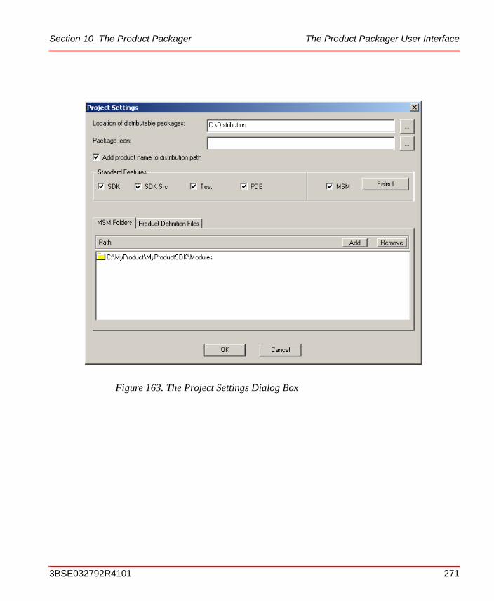
Section 10 The Product Packager The Product Packager User Interface
Figure 163. The Project Settings Dialog Box
3BSE032792R4101 271
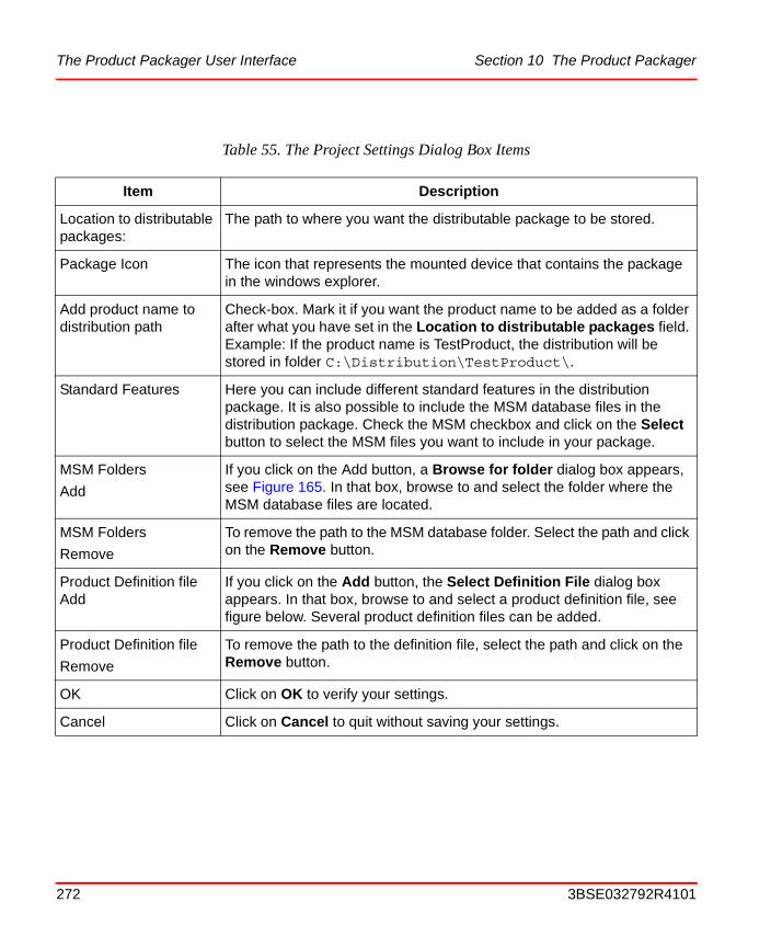
The Product Packager User Interface Section 10 The Product Packager
Table 55. The Project Settings Dialog Box Items
Item Description
Location to distributable packages:
The path to where you want the distributable package to be stored.
Package Icon The icon that represents the mounted device that contains the package in the windows explorer.
Add product name to distribution path
Check-box. Mark it if you want the product name to be added as a folder after what you have set in the Location to distributable packages field. Example: If the product name is TestProduct, the distribution will be stored in folder C:\Distribution\TestProduct\.
Standard Features Here you can include different standard features in the distribution package. It is also possible to include the MSM database files in the distribution package. Check the MSM checkbox and click on the Select button to select the MSM files you want to include in your package.
MSM Folders
Add
If you click on the Add button, a Browse for folder dialog box appears, see Figure 165. In that box, browse to and select the folder where the MSM database files are located.
MSM Folders
Remove
To remove the path to the MSM database folder. Select the path and click on the Remove button.
Product Definition file Add
If you click on the Add button, the Select Definition File dialog box appears. In that box, browse to and select a product definition file, see figure below. Several product definition files can be added.
Product Definition file
Remove
To remove the path to the definition file, select the path and click on the Remove button.
OK Click on OK to verify your settings.
Cancel Click on Cancel to quit without saving your settings.
272 3BSE032792R4101
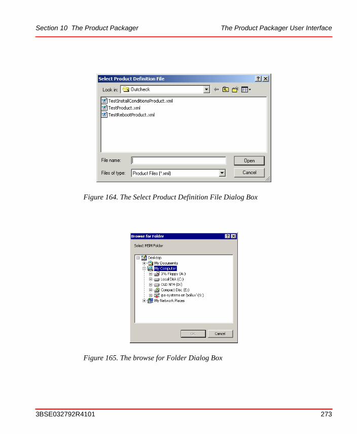
Section 10 The Product Packager The Product Packager User Interface
Figure 164. The Select Product Definition File Dialog Box
Figure 165. The browse for Folder Dialog Box
3BSE032792R4101 273
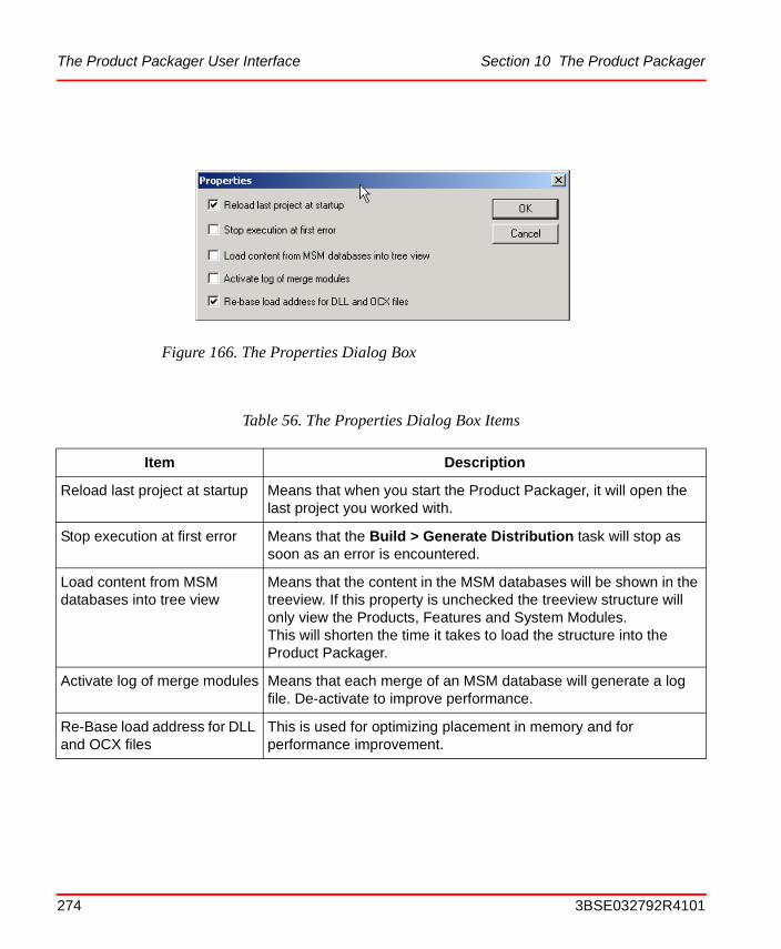
The Product Packager User Interface Section 10 The Product Packager
Figure 166. The Properties Dialog Box
Table 56. The Properties Dialog Box Items
Item Description
Reload last project at startup Means that when you start the Product Packager, it will open the last project you worked with.
Stop execution at first error Means that the Build > Generate Distribution task will stop as soon as an error is encountered.
Load content from MSM databases into tree view
Means that the content in the MSM databases will be shown in the treeview. If this property is unchecked the treeview structure will only view the Products, Features and System Modules. This will shorten the time it takes to load the structure into the Product Packager.
Activate log of merge modules Means that each merge of an MSM database will generate a log file. De-activate to improve performance.
Re-Base load address for DLL and OCX files
This is used for optimizing placement in memory and for performance improvement.
274 3BSE032792R4101
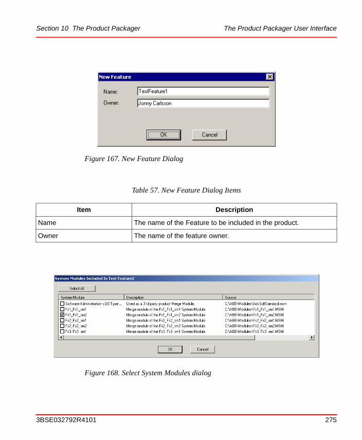
Section 10 The Product Packager The Product Packager User Interface
Figure 167. New Feature Dialog
Table 57. New Feature Dialog Items
Item Description
Name The name of the Feature to be included in the product.
Owner The name of the feature owner.
Figure 168. Select System Modules dialog
3BSE032792R4101 275

The Product Packager User Interface Section 10 The Product Packager
If you choose a “product” in the tree, you can use this dialog to show which System Modules (MSM) are currently contained in the product. You will then get an overview, and you can easily detect if there are MSMs (new System Modules) in the MSM folder which have not yet been included in the product package (means that they have been added after the previous build). The dialog is read-only, and you must select an existing feature, or create one, if you want to add the new MSM (System Module).
The left upper view. Shows the product trees. That is, from the top, the Products, Features, System Modules, and Components. If the “Load content from MSM databases into tree view“ is not checked in the properties dialog box only Products, Features and System Modules are shown.
The right upper view. This view sets the configuration properties for the item that you have selected in the left treeview. When a product is selected six tabs, marked: General, Billboards, Supported Platforms, File Install Conditions, Product Install Conditions, and Product Upgrades will appear.
276 3BSE032792R4101
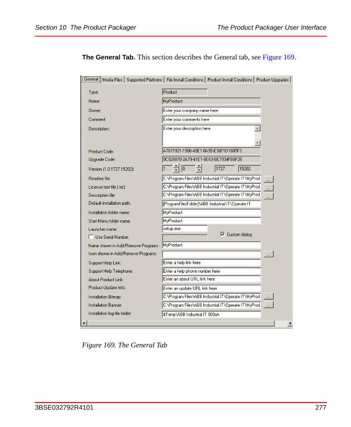
Section 10 The Product Packager The Product Packager User Interface
The General Tab. This section describes the General tab, see Figure 169.
Figure 169. The General Tab
3BSE032792R4101 277

The Product Packager User Interface Section 10 The Product Packager
Table 58. General Tab Items
Item Description
Type Specify if the selected item is a Root-, Product-, Feature-, System Module- or Component-item.
Name The name of the selected product.
Owner The name of the product owner.
Comment A short comment about the product. This option is only available if the selected item is a product, and can then be edited by the user.
Description A brief textual description of the selected item. It can be changed by the user if the selected item is a product or a feature.
Product Code A GUID that identifies the product. This code can not be changed in the Product Packager.
Upgrade Code A GUID that is used to search for related installed versions of a product and should be affected by the upgrade. This code can not be changed in the Product Packager.
Version The version number of the product. It can not be changed in the Product Packager
Readme file The path to the product Readmefile. The Readmefile can be in any format that is supported by Windows Explorer, for example .HTML.
License textfile The path to the license text file. It will be displayed during the installation of the generated product package. It must be ASCII file. (.txt)
Description file The path to a file that contains a description of the selected product. It will be displayed during the installation of the package. The file format supported is.RTF and.TXT. Required when creating a distribution.
Default installation path This option specifies the default installation path. It will be used during the package installation, if the user doesn’t specify any path. Required when creating a distribution.
278 3BSE032792R4101
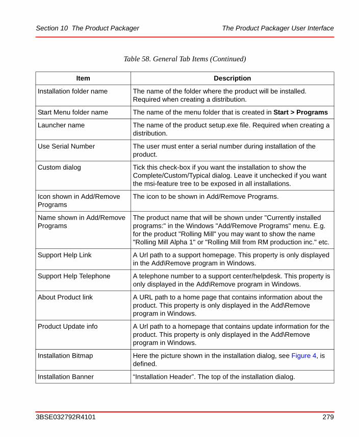
Section 10 The Product Packager The Product Packager User Interface
Installation folder name The name of the folder where the product will be installed. Required when creating a distribution.
Start Menu folder name The name of the menu folder that is created in Start > Programs
Launcher name The name of the product setup.exe file. Required when creating a distribution.
Use Serial Number The user must enter a serial number during installation of the product.
Custom dialog Tick this check-box if you want the installation to show the Complete/Custom/Typical dialog. Leave it unchecked if you want the msi-feature tree to be exposed in all installations.
Icon shown in Add/Remove Programs
The icon to be shown in Add/Remove Programs.
Name shown in Add/Remove Programs
The product name that will be shown under "Currently installed programs:" in the Windows "Add/Remove Programs" menu. E.g. for the product "Rolling Mill" you may want to show the name "Rolling Mill Alpha 1" or "Rolling Mill from RM production inc." etc.
Support Help Link A Url path to a support homepage. This property is only displayed in the Add\Remove program in Windows.
Support Help Telephone A telephone number to a support center/helpdesk. This property is only displayed in the Add\Remove program in Windows.
About Product link A URL path to a home page that contains information about the product. This property is only displayed in the Add\Remove program in Windows.
Product Update info A Url path to a homepage that contains update information for the product. This property is only displayed in the Add\Remove program in Windows.
Installation Bitmap Here the picture shown in the installation dialog, see Figure 4, is defined.
Installation Banner “Installation Header”. The top of the installation dialog.
Table 58. General Tab Items (Continued)
Item Description
3BSE032792R4101 279
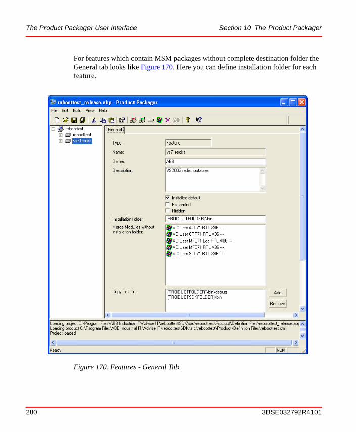
The Product Packager User Interface Section 10 The Product Packager
For features which contain MSM packages without complete destination folder the General tab looks like Figure 170. Here you can define installation folder for each feature.
Figure 170. Features - General Tab
280 3BSE032792R4101
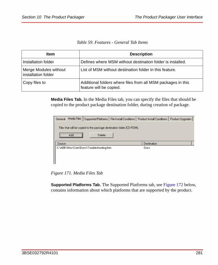
Section 10 The Product Packager The Product Packager User Interface
Media Files Tab. In the Media Files tab, you can specify the files that should be copied to the product package destination folder, during creation of package.
Supported Platforms Tab. The Supported Platforms tab, see Figure 172 below, contains information about which platforms that are supported by the product.
Table 59. Features - General Tab Items
Item Description
Installation folder Defines where MSM without destination folder is installed.
Merge Modules without installation folder
List of MSM without destination folder in this feature.
Copy files to Additional folders where files from all MSM packages in this feature will be copied.
Figure 171. Media Files Tab
3BSE032792R4101 281
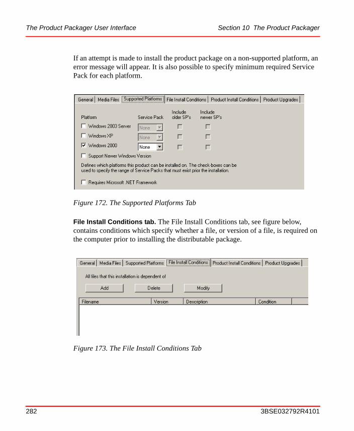
The Product Packager User Interface Section 10 The Product Packager
If an attempt is made to install the product package on a non-supported platform, an error message will appear. It is also possible to specify minimum required Service Pack for each platform.
File Install Conditions tab. The File Install Conditions tab, see figure below, contains conditions which specify whether a file, or version of a file, is required on the computer prior to installing the distributable package.
Figure 172. The Supported Platforms Tab
Figure 173. The File Install Conditions Tab
282 3BSE032792R4101
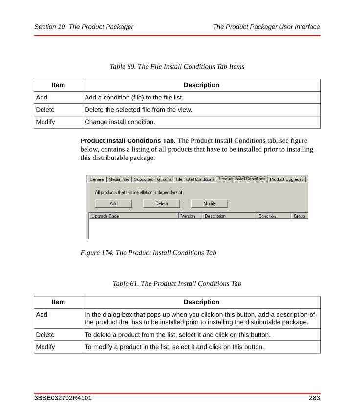
Section 10 The Product Packager The Product Packager User Interface
Product Install Conditions Tab. The Product Install Conditions tab, see figure below, contains a listing of all products that have to be installed prior to installing this distributable package.
Table 60. The File Install Conditions Tab Items
Item Description
Add Add a condition (file) to the file list.
Delete Delete the selected file from the view.
Modify Change install condition.
Figure 174. The Product Install Conditions Tab
Table 61. The Product Install Conditions Tab
Item Description
Add In the dialog box that pops up when you click on this button, add a description of the product that has to be installed prior to installing the distributable package.
Delete To delete a product from the list, select it and click on this button.
Modify To modify a product in the list, select it and click on this button.
3BSE032792R4101 283
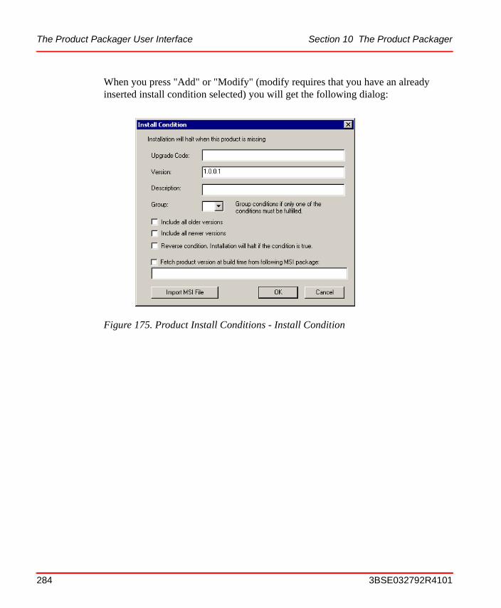
The Product Packager User Interface Section 10 The Product Packager
When you press "Add" or "Modify" (modify requires that you have an already inserted install condition selected) you will get the following dialog:
Figure 175. Product Install Conditions - Install Condition
284 3BSE032792R4101
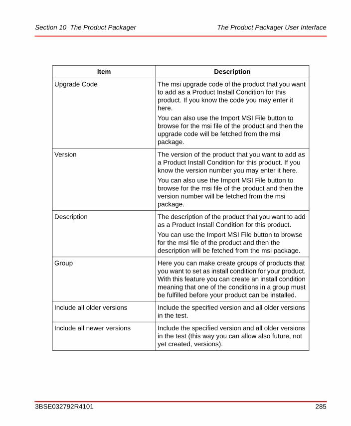
Section 10 The Product Packager The Product Packager User Interface
Item Description
Upgrade Code The msi upgrade code of the product that you want to add as a Product Install Condition for this product. If you know the code you may enter it here.
You can also use the Import MSI File button to browse for the msi file of the product and then the upgrade code will be fetched from the msi package.
Version The version of the product that you want to add as a Product Install Condition for this product. If you know the version number you may enter it here.
You can also use the Import MSI File button to browse for the msi file of the product and then the version number will be fetched from the msi package.
Description The description of the product that you want to add as a Product Install Condition for this product.
You can use the Import MSI File button to browse for the msi file of the product and then the description will be fetched from the msi package.
Group Here you can make create groups of products that you want to set as install condition for your product. With this feature you can create an install condition meaning that one of the conditions in a group must be fulfilled before your product can be installed.
Include all older versions Include the specified version and all older versions in the test.
Include all newer versions Include the specified version and all older versions in the test (this way you can allow also future, not yet created, versions).
3BSE032792R4101 285
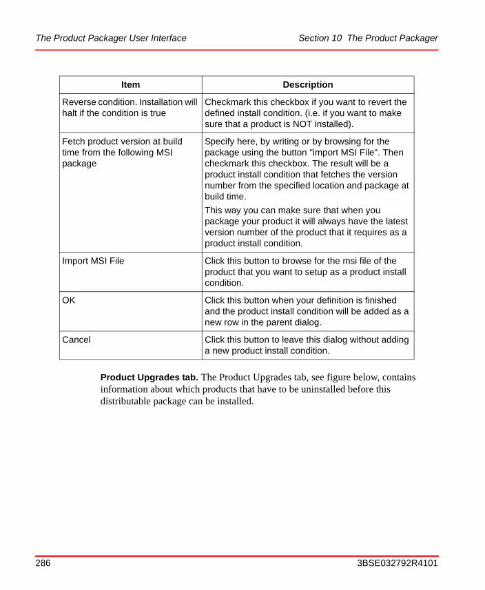
The Product Packager User Interface Section 10 The Product Packager
Product Upgrades tab. The Product Upgrades tab, see figure below, contains information about which products that have to be uninstalled before this distributable package can be installed.
Reverse condition. Installation will halt if the condition is true
Checkmark this checkbox if you want to revert the defined install condition. (i.e. if you want to make sure that a product is NOT installed).
Fetch product version at build time from the following MSI package
Specify here, by writing or by browsing for the package using the button "import MSI File". Then checkmark this checkbox. The result will be a product install condition that fetches the version number from the specified location and package at build time.
This way you can make sure that when you package your product it will always have the latest version number of the product that it requires as a product install condition.
Import MSI File Click this button to browse for the msi file of the product that you want to setup as a product install condition.
OK Click this button when your definition is finished and the product install condition will be added as a new row in the parent dialog.
Cancel Click this button to leave this dialog without adding a new product install condition.
Item Description
286 3BSE032792R4101

Section 10 The Product Packager The Product Packager User Interface
During the installation of the distributable package, the specified products will be uninstalled automatically. The view contains paths to the products .MSI files.
The status view. When you start a function, for example Build > Generate Distribution, error and/or success messages will be displayed in the status view, at the bottom of the window.
Figure 176. The Product Upgrades Tab
Table 62. The Product Upgrades Tab
Item Description
Add Add a path to the .msi file of the Product that has to be un-installed before the distributable package could be installed.
Delete Delete the selected product path from the view.
3BSE032792R4101 287
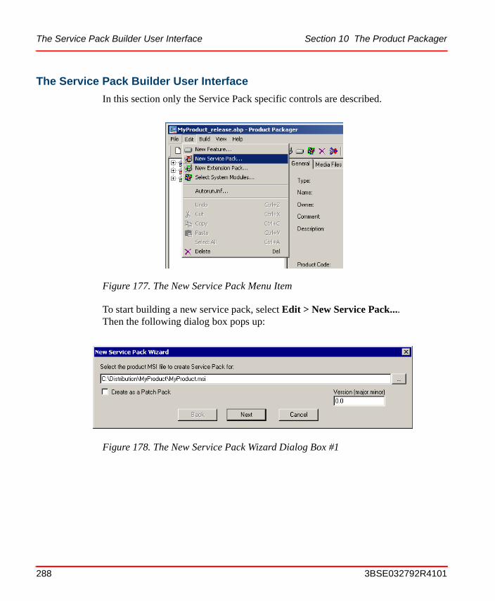
The Service Pack Builder User Interface Section 10 The Product Packager
The Service Pack Builder User Interface
In this section only the Service Pack specific controls are described.
To start building a new service pack, select Edit > New Service Pack.... Then the following dialog box pops up:
Figure 177. The New Service Pack Menu Item
Figure 178. The New Service Pack Wizard Dialog Box #1
288 3BSE032792R4101
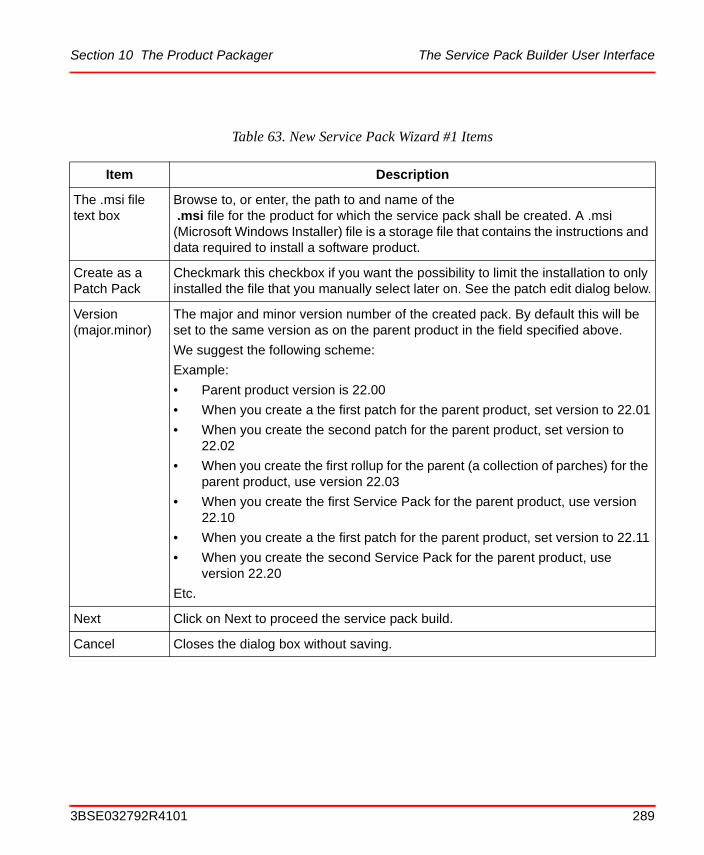
Section 10 The Product Packager The Service Pack Builder User Interface
Table 63. New Service Pack Wizard #1 Items
Item Description
The .msi file text box
Browse to, or enter, the path to and name of the .msi file for the product for which the service pack shall be created. A .msi (Microsoft Windows Installer) file is a storage file that contains the instructions and data required to install a software product.
Create as a Patch Pack
Checkmark this checkbox if you want the possibility to limit the installation to only installed the file that you manually select later on. See the patch edit dialog below.
Version (major.minor)
The major and minor version number of the created pack. By default this will be set to the same version as on the parent product in the field specified above.
We suggest the following scheme:
Example:
• Parent product version is 22.00
• When you create a the first patch for the parent product, set version to 22.01
• When you create the second patch for the parent product, set version to 22.02
• When you create the first rollup for the parent (a collection of parches) for the parent product, use version 22.03
• When you create the first Service Pack for the parent product, use version 22.10
• When you create a the first patch for the parent product, set version to 22.11
• When you create the second Service Pack for the parent product, use version 22.20
Etc.
Next Click on Next to proceed the service pack build.
Cancel Closes the dialog box without saving.
3BSE032792R4101 289
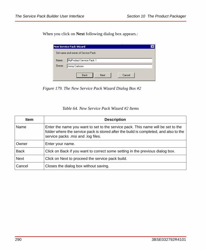
The Service Pack Builder User Interface Section 10 The Product Packager
When you click on Next following dialog box appears.:
Figure 179. The New Service Pack Wizard Dialog Box #2
Table 64. New Service Pack Wizard #2 Items
Item Description
Name Enter the name you want to set to the service pack. This name will be set to the folder where the service pack is stored after the build is completed, and also to the service packs .msi and .log files.
Owner Enter your name.
Back Click on Back if you want to correct some setting in the previous dialog box.
Next Click on Next to proceed the service pack build.
Cancel Closes the dialog box without saving.
290 3BSE032792R4101
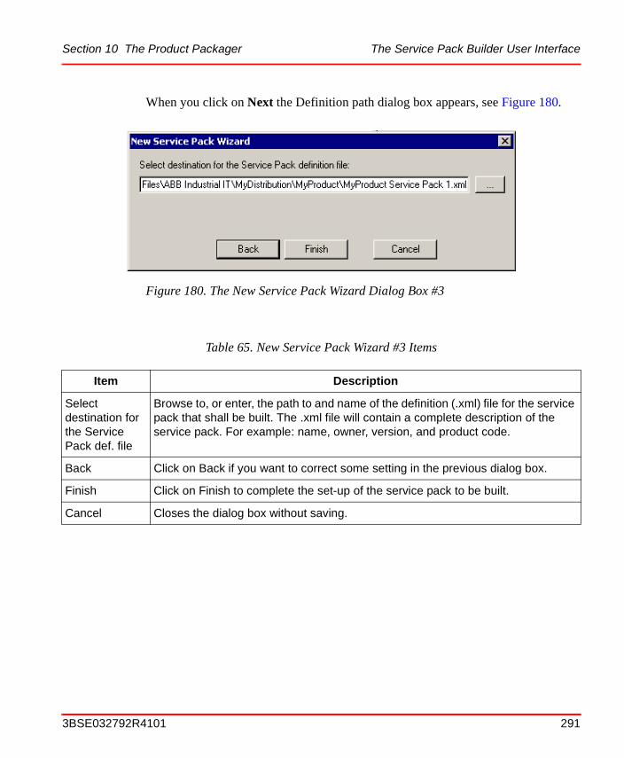
Section 10 The Product Packager The Service Pack Builder User Interface
When you click on Next the Definition path dialog box appears, see Figure 180.
Figure 180. The New Service Pack Wizard Dialog Box #3
Table 65. New Service Pack Wizard #3 Items
Item Description
Select destination for the Service Pack def. file
Browse to, or enter, the path to and name of the definition (.xml) file for the service pack that shall be built. The .xml file will contain a complete description of the service pack. For example: name, owner, version, and product code.
Back Click on Back if you want to correct some setting in the previous dialog box.
Finish Click on Finish to complete the set-up of the service pack to be built.
Cancel Closes the dialog box without saving.
3BSE032792R4101 291

The Extension Pack Builder User Interface Section 10 The Product Packager
When you click on Finish, the service pack will appear in the left tree view in the Product Packager dialog:.
To build the service pack, select Build > Generate Distribution. The complete service pack, ready for distribution, will then be built and stored in folder MyProduct Service Pack 1, under the distribution folder specified for the product:
The Extension Pack Builder User Interface
Please see Tutorial 4 - Creation of an Extension Pack on page 248 for information about the Extension Pack Builder user interface.
Figure 181. The Service Pack in the Product Tree View
Figure 182. The Service Pack Distribution Folder
292 3BSE032792R4101
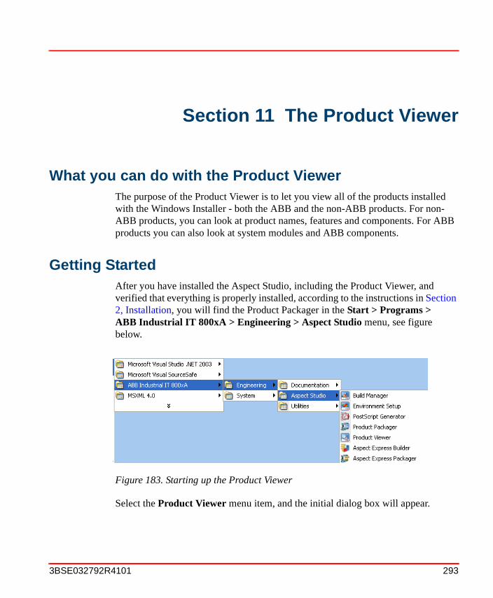
Section 11 The Product Viewer
What you can do with the Product ViewerThe purpose of the Product Viewer is to let you view all of the products installed with the Windows Installer - both the ABB and the non-ABB products. For non-ABB products, you can look at product names, features and components. For ABB products you can also look at system modules and ABB components.
Getting StartedAfter you have installed the Aspect Studio, including the Product Viewer, and verified that everything is properly installed, according to the instructions in Section 2, Installation, you will find the Product Packager in the Start > Programs > ABB Industrial IT 800xA > Engineering > Aspect Studio menu, see figure below.
Select the Product Viewer menu item, and the initial dialog box will appear.
Figure 183. Starting up the Product Viewer
3BSE032792R4101 293
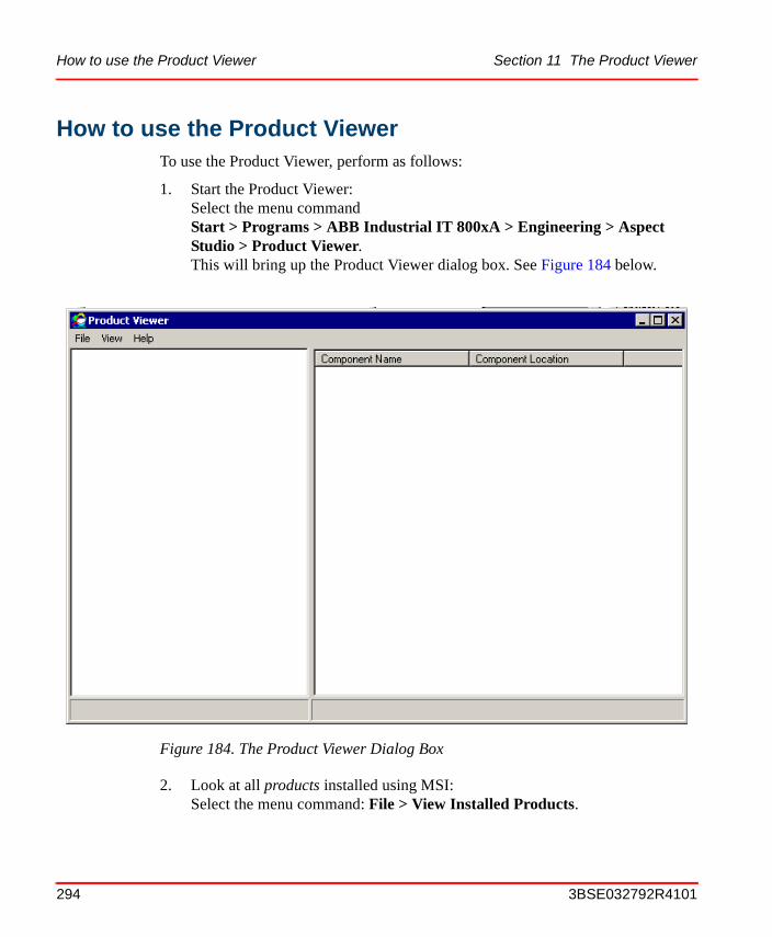
How to use the Product Viewer Section 11 The Product Viewer
How to use the Product ViewerTo use the Product Viewer, perform as follows:
1. Start the Product Viewer:Select the menu commandStart > Programs > ABB Industrial IT 800xA > Engineering > Aspect Studio > Product Viewer.This will bring up the Product Viewer dialog box. See Figure 184 below.
2. Look at all products installed using MSI:Select the menu command: File > View Installed Products.
Figure 184. The Product Viewer Dialog Box
294 3BSE032792R4101
Section 11 The Product Viewer Product Viewer User Interface
3. Look at all components in a specific product:Click on the product of interest, in the left list box. Then all of the product components will appear in the right list box.
4. Look at the properties for a specific product:
– Right click on the product, in the left list box
– Select Properties...
– A message box with three tabs, General, File List, and Patches appears.
Note that you can also achieve this by first selecting the product, and then use the menu command: View > Properties > Product Properties....
On the Patches tab it is possible to view the description text for each installed patch. To view the text double-click on the patch name.
5. Look at the properties for a specific component:
– Right click on the component (in the right list box).
– Select Properties...
– A message box with three tabs, General, File List, and Patches appears.
Note that you can also achieve this by first selecting the component, and then use the menu command: View > Properties > Component Properties....
6. Set preferences:
– Select the menu command: View > Preferences...The Preferences dialog box appears.
– Check the settings you want.
Product Viewer User InterfaceThe figure below shows the Product Viewer entry dialog, opened with the menu command: Start > Programs > ABB Industrial IT 800xA > Engineering > Aspect Studio > Product Viewer.
3BSE032792R4101 295
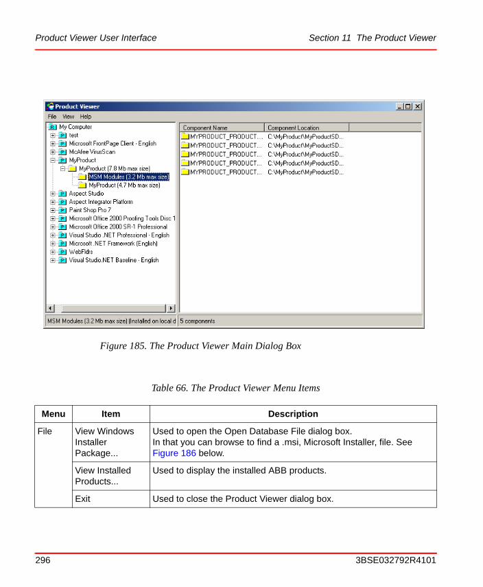
Product Viewer User Interface Section 11 The Product Viewer
Figure 185. The Product Viewer Main Dialog Box
Table 66. The Product Viewer Menu Items
Menu Item Description
File View Windows Installer Package...
Used to open the Open Database File dialog box. In that you can browse to find a .msi, Microsoft Installer, file. See Figure 186 below.
View Installed Products...
Used to display the installed ABB products.
Exit Used to close the Product Viewer dialog box.
296 3BSE032792R4101
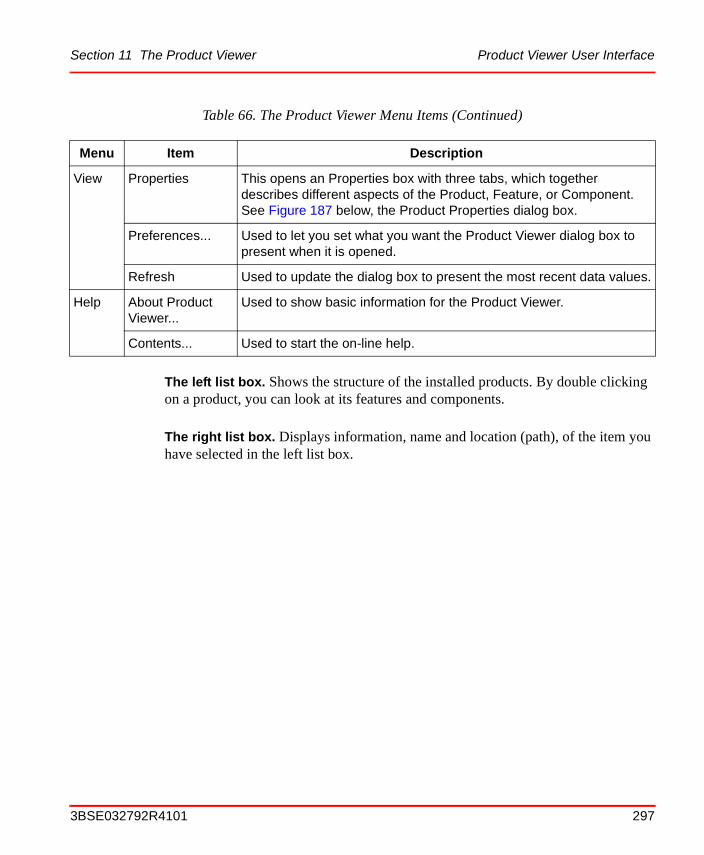
Section 11 The Product Viewer Product Viewer User Interface
The left list box. Shows the structure of the installed products. By double clicking on a product, you can look at its features and components.
The right list box. Displays information, name and location (path), of the item you have selected in the left list box.
View Properties This opens an Properties box with three tabs, which together describes different aspects of the Product, Feature, or Component. See Figure 187 below, the Product Properties dialog box.
Preferences... Used to let you set what you want the Product Viewer dialog box to present when it is opened.
Refresh Used to update the dialog box to present the most recent data values.
Help About Product Viewer...
Used to show basic information for the Product Viewer.
Contents... Used to start the on-line help.
Table 66. The Product Viewer Menu Items (Continued)
Menu Item Description
3BSE032792R4101 297
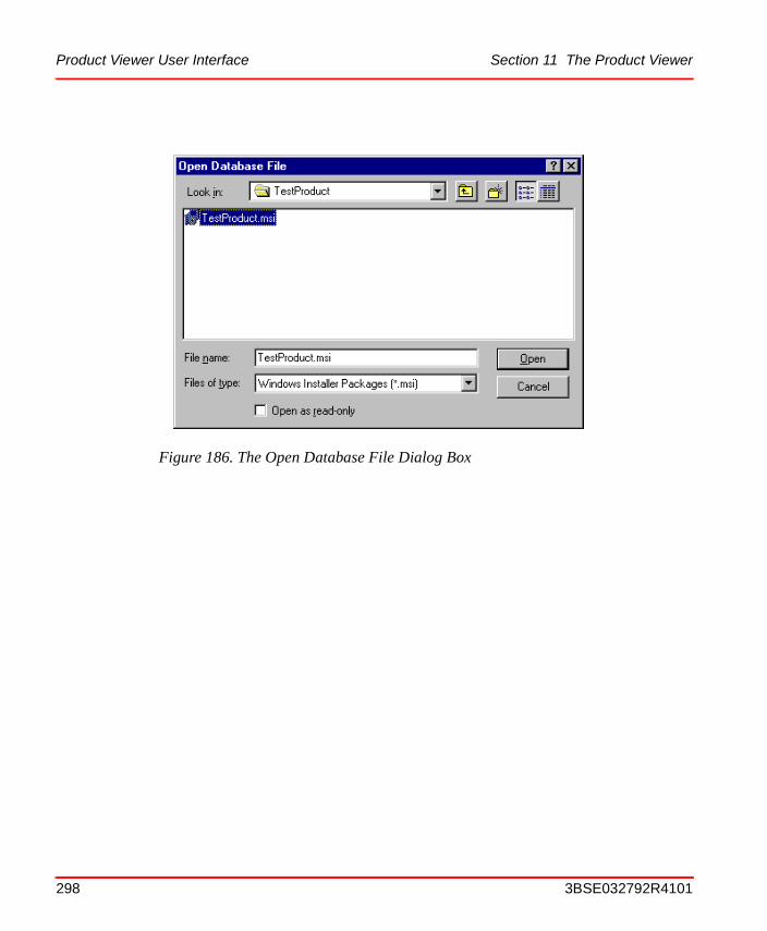
Product Viewer User Interface Section 11 The Product Viewer
Figure 186. The Open Database File Dialog Box
298 3BSE032792R4101

Section 11 The Product Viewer Product Viewer User Interface
Figure 187. The Product Properties Dialog Box - General Tab
3BSE032792R4101 299
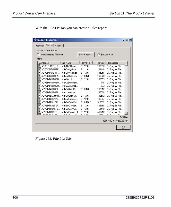
Product Viewer User Interface Section 11 The Product Viewer
With the File List tab you can create a Files report.
Figure 188. File List Tab
300 3BSE032792R4101

Section 11 The Product Viewer Product Viewer User Interface
Keep the Exclude Path checkbox checked if you don’t want the file paths specified in the report. Include file path for file report generation will take more time. Click on the Files Report button and the following dialog opens:
Figure 189. Files Report Dialog
Table 67. New Product Dialog Items
Item Description
Report to The report can be displayed in Microsoft Excel, Notepad or copy to clipboard. Select one of the radio buttons to choose the report target.
All files Mark this radio button if you want to show all files.
Versioned Files Only Mark this radio button if you just want to see the versioned image files, such as DLL, EXE or OCX.
Display Selected Files Mark this radio button if you want to display a certain type of files, an editing box lets you define the file name or types.
OK Click OK to display the result.
Hide Click Hide button to close the dialog.
3BSE032792R4101 301
Product Viewer User Interface Section 11 The Product Viewer
302 3BSE032792R4101
Section 12 Maintenance
Preventive MaintenanceNo specific maintenance procedures are required for the Aspect Studio software-package.
Error Messages
Error Messages from the Product Packager
In the Product Packager status window
Message: Error: MsiOpenDatabase (C:\Program files\ABB Industrial IT\800xA System\Engineering\Aspect Studio\Test.MSM) failed - (C:\Distribution\Aspect Studio\Aspect Studio.msi) ERROR_OPEN_FAILED = The system cannot open the device or file specified
Reason/action: Means that the specified file, Test.MSM, can not be found. Check if it exists, in the specified folder, and that you are authorized to access it.
An error/mistake that gives no message
Suppose you modify, for example, a system module or a component, then create a new distributable packet, and the modification does not seem to be in effect in the new packet. Then a reason might be that you have forgotten to re-build the MSM databases after you modified, and before you built the new packet.
3BSE032792R4101 303

Error Messages Section 12 Maintenance
304 3BSE032792R4101

Appendix A Build ABC File Configuration
Functional Overview
General
An ABC file configuration consists of the build files that describe how to build a product including both the compile and link and the build of Microsoft Merge Modules (MSMs). These build files correspond to Functional Subsystems, System Modules and Components. The system also uses an overall build file called a root file that specifies the Functional Subsystems to be built.
The development structure used to develop the ABB Automation software is illustrated in the figure below.
Note that the structure contains four levels, the root level, the functional subsystem level, the system module level and the component level.
When the system is built it will generate product composition information consisting of a system module listing (including dependencies) and four ‘loadable’ product categories.
Figure 190. Example of a Build Tree
Root
FS1
FS2SM1
Comp1
3BSE032792R4101 305
The Development Structure Appendix A Build ABC File Configuration
The build files, which is the basis for this system module, are described in The Build Files on page 307.
Two categories of users are identified in the system. The product integrators who builds a full system, and the developers who works within a specific functional subsystem. The latter category of users are typically assigned to work within one particular system module.
The Development Structure
The development structure consists of four levels. The first, upper, three levels of the development structure are strict, i.e. the children of the root level are always functional subsystem etc. The fourth level, the component level, allows a free form. That is, the different components of a system module can be placed in an arbitrary tree structure placed under the system module. Some conventions to control how the component level is structured are described later in this document.
The root level, called Root in figure Figure 190, is given a name that corresponds to the build that is described by the tree.
VSS (Visual SourceSafe) is used to revision handle the software (and the documents). In VSS, a project structure is used (above what is illustrated in Figure 190). The root of the VSS project structure is named ‘$’. Under the root, there are three projects, Work, Baselines and Releases.
The Work project contains the main development tracks. The Work structure can contain other projects (roots) as your system continues to evolve.
The Baselines project contains branched versions of the main development tracks. Typically the software is branched something like every week and the roots for a particular baseline is normally named something like w911 (week 1999/11).
The branched projects are typically not branched in VSS terminology, they represents pinned versions of main development tracks but could, when desired, be real branches.
The Release project contains releases and release candidates (i.e. branches that are getting close to a release). It is recommended that all releases are given meaningful names, for example Automation1.0-Alpha3.
306 3BSE032792R4101
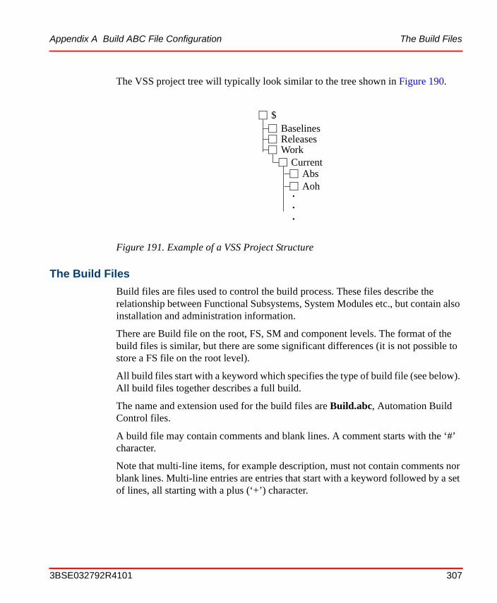
Appendix A Build ABC File Configuration The Build Files
The VSS project tree will typically look similar to the tree shown in Figure 190.
The Build Files
Build files are files used to control the build process. These files describe the relationship between Functional Subsystems, System Modules etc., but contain also installation and administration information.
There are Build file on the root, FS, SM and component levels. The format of the build files is similar, but there are some significant differences (it is not possible to store a FS file on the root level).
All build files start with a keyword which specifies the type of build file (see below). All build files together describes a full build.
The name and extension used for the build files are Build.abc, Automation Build Control files.
A build file may contain comments and blank lines. A comment starts with the ‘#’ character.
Note that multi-line items, for example description, must not contain comments nor blank lines. Multi-line entries are entries that start with a keyword followed by a set of lines, all starting with a plus (‘+’) character.
Figure 191. Example of a VSS Project Structure
BaselinesReleasesWork
Abs
$
Current
Aoh...
3BSE032792R4101 307
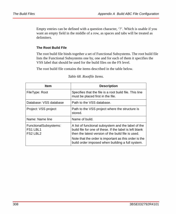
The Build Files Appendix A Build ABC File Configuration
Empty entries can be defined with a question character, ‘?’. Which is usable if you want an empty field in the middle of a row, as spaces and tabs will be treated as delimiters.
The Root Build File
The root build file binds together a set of Functional Subsystems. The root build file lists the Functional Subsystems one by, one and for each of them it specifies the VSS label that should be used for the build files on the FS level.
The root build file contains the items described in the table below.
Table 68. Rootfile Items.
Item Description
FileType: Root Specifies that the file is a root build file. This line must be placed first in the file.
Database: VSS database Path to the VSS database.
Project: VSS project Path to the VSS project where the structure is stored.
Name: Name line Name of build.
FunctionalSubsystems:FS1 LBL1FS2 LBL2
A list of functional subsystem and the label of the build file for one of these. If the label is left blank then the latest version of the build file is used.
Note that the order is important as this order is the build order imposed when building a full system.
308 3BSE032792R4101
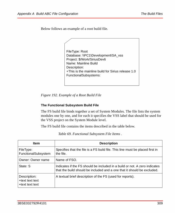
Appendix A Build ABC File Configuration The Build Files
Below follows an example of a root build file.
The Functional Subsystem Build File
The FS build file binds together a set of System Modules. The file lists the system modules one by one, and for each it specifies the VSS label that should be used for the VSS project on the System Module level.
The FS build file contains the items described in the table below.
Figure 192. Example of a Root Build File
Table 69. Functional Subsystem File Items .
Item Description
FileType: FunctionalSubsystem
Specifies that the file is a FS build file. This line must be placed first in the file.
Owner: Owner name Name of FSO.
State: S Indicates if the FS should be included in a build or not. A zero indicates that the build should be included and a one that it should be excluded.
Description:+text text text+text text text
A textual brief description of the FS (used for reports).
FileType: RootDatabase: \\PC1\Development\SA_vssProject: $/Work/SiriusDev6Name: Mainline BuildDescription:+This is the mainline build for Sirius release 1.0FunctionalSubsystems:
3BSE032792R4101 309
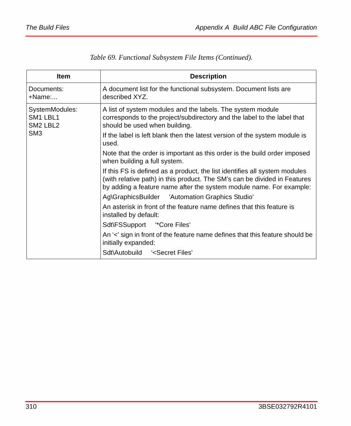
The Build Files Appendix A Build ABC File Configuration
Documents:+Name:...
A document list for the functional subsystem. Document lists are described XYZ.
SystemModules:SM1 LBL1SM2 LBL2SM3
A list of system modules and the labels. The system module corresponds to the project/subdirectory and the label to the label that should be used when building.
If the label is left blank then the latest version of the system module is used.
Note that the order is important as this order is the build order imposed when building a full system.
If this FS is defined as a product, the list identifies all system modules (with relative path) in this product. The SM’s can be divided in Features by adding a feature name after the system module name. For example:
Ag\GraphicsBuilder 'Automation Graphics Studio'
An asterisk in front of the feature name defines that this feature is installed by default:
Sdt\FSSupport '*Core Files'
An ‘<’ sign in front of the feature name defines that this feature should be initially expanded:
Sdt\Autobuild '<Secret Files'
Table 69. Functional Subsystem File Items (Continued).
Item Description
310 3BSE032792R4101

Appendix A Build ABC File Configuration The Build Files
Below follows an example of a functional subsystem build file.
The System Module Build File
The System Module build file lists the components the are part of a System Module. The file also contains some additional information.
Figure 193. Example of a Functional Subsystem Build File
FileType: FunctionalSubsystemOwner: Ingeborg CarlssonState: 0Description:+Automation Graphics Functional SubsystemDocuments:#+DocName:Number:Title:Resp:Remain:Prio:Due:Ready:Comment#+DocName:Number:Title:Resp:Remain:Prio:Due:Ready:CommentSystemModules:#SM1 LABEL1
# no label means “latest version”
GraphicsCommonGraphicsViewerGraphicsDialogGraphicsBuilderDoc
3BSE032792R4101 311
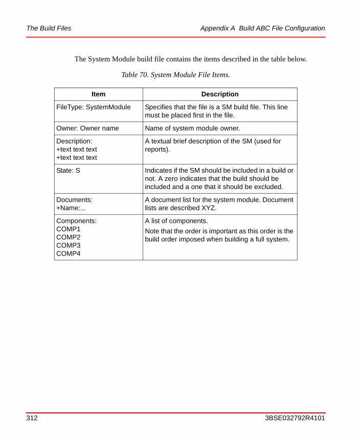
The Build Files Appendix A Build ABC File Configuration
The System Module build file contains the items described in the table below.
Table 70. System Module File Items.
Item Description
FileType: SystemModule Specifies that the file is a SM build file. This line must be placed first in the file.
Owner: Owner name Name of system module owner.
Description:+text text text+text text text
A textual brief description of the SM (used for reports).
State: S Indicates if the SM should be included in a build or not. A zero indicates that the build should be included and a one that it should be excluded.
Documents:+Name:...
A document list for the system module. Document lists are described XYZ.
Components:COMP1COMP2COMP3COMP4
A list of components.
Note that the order is important as this order is the build order imposed when building a full system.
312 3BSE032792R4101

Appendix A Build ABC File Configuration The Build Files
Below is an example of a System Module build file.
The Component Build File
The component build file lists the files the are part of the component. These files include the source files and the files built in a full build. The file also contains information about how the files shall be installed and where.
Figure 194. Example of a System Module Build File
FileType: SystemModuleOwner: Johan S Andersson/LKAState: 0VersionId: 100Description:+COM library to access build filesDocuments:#+DocName:Number:Title:Resp:Remain:Prio:Due:Ready:CommentComponents:AdvSdtFSSupportAdvSdtToolAdvSdtBuildFilesAdvSdtRTFReportAdvSdtRebaseDoc
3BSE032792R4101 313
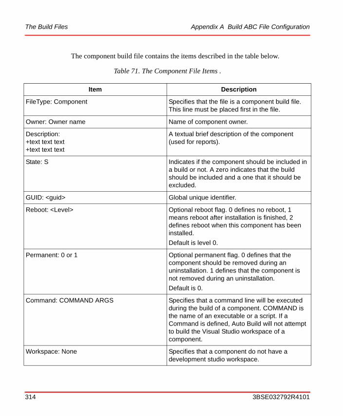
The Build Files Appendix A Build ABC File Configuration
The component build file contains the items described in the table below.
Table 71. The Component File Items .
Item Description
FileType: Component Specifies that the file is a component build file. This line must be placed first in the file.
Owner: Owner name Name of component owner.
Description:+text text text+text text text
A textual brief description of the component (used for reports).
State: S Indicates if the component should be included in a build or not. A zero indicates that the build should be included and a one that it should be excluded.
GUID: <guid> Global unique identifier.
Reboot: <Level> Optional reboot flag. 0 defines no reboot, 1 means reboot after installation is finished, 2 defines reboot when this component has been installed.
Default is level 0.
Permanent: 0 or 1 Optional permanent flag. 0 defines that the component should be removed during an uninstallation. 1 defines that the component is not removed during an uninstallation.
Default is 0.
Command: COMMAND ARGS Specifies that a command line will be executed during the build of a component. COMMAND is the name of an executable or a script. If a Command is defined, Auto Build will not attempt to build the Visual Studio workspace of a component.
Workspace: None Specifies that a component do not have a development studio workspace.
314 3BSE032792R4101
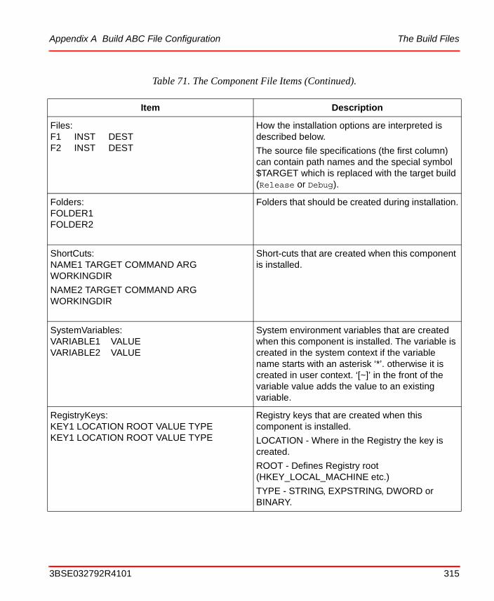
Appendix A Build ABC File Configuration The Build Files
Files:F1 INST DESTF2 INST DEST
How the installation options are interpreted is described below.
The source file specifications (the first column) can contain path names and the special symbol $TARGET which is replaced with the target build (Release or Debug).
Folders:FOLDER1FOLDER2
Folders that should be created during installation.
ShortCuts:NAME1 TARGET COMMAND ARG WORKINGDIR
NAME2 TARGET COMMAND ARG WORKINGDIR
Short-cuts that are created when this component is installed.
SystemVariables:VARIABLE1 VALUEVARIABLE2 VALUE
System environment variables that are created when this component is installed. The variable is created in the system context if the variable name starts with an asterisk ‘*’. otherwise it is created in user context. ‘[~]’ in the front of the variable value adds the value to an existing variable.
RegistryKeys:KEY1 LOCATION ROOT VALUE TYPEKEY1 LOCATION ROOT VALUE TYPE
Registry keys that are created when this component is installed.
LOCATION - Where in the Registry the key is created.
ROOT - Defines Registry root (HKEY_LOCAL_MACHINE etc.)
TYPE - STRING, EXPSTRING, DWORD or BINARY.
Table 71. The Component File Items (Continued).
Item Description
3BSE032792R4101 315
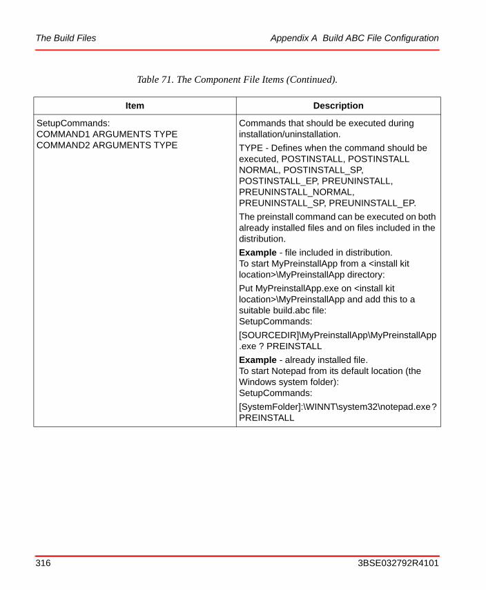
The Build Files Appendix A Build ABC File Configuration
SetupCommands:COMMAND1 ARGUMENTS TYPECOMMAND2 ARGUMENTS TYPE
Commands that should be executed during installation/uninstallation.
TYPE - Defines when the command should be executed, POSTINSTALL, POSTINSTALL NORMAL, POSTINSTALL_SP, POSTINSTALL_EP, PREUNINSTALL, PREUNINSTALL_NORMAL, PREUNINSTALL_SP, PREUNINSTALL_EP.
The preinstall command can be executed on both already installed files and on files included in the distribution.
Example - file included in distribution.To start MyPreinstallApp from a <install kit location>\MyPreinstallApp directory:
Put MyPreinstallApp.exe on <install kit location>\MyPreinstallApp and add this to a suitable build.abc file: SetupCommands:
[SOURCEDIR]\MyPreinstallApp\MyPreinstallApp.exe ? PREINSTALL
Example - already installed file.To start Notepad from its default location (the Windows system folder):SetupCommands:
[SystemFolder]:\WINNT\system32\notepad.exe ? PREINSTALL
Table 71. The Component File Items (Continued).
Item Description
316 3BSE032792R4101
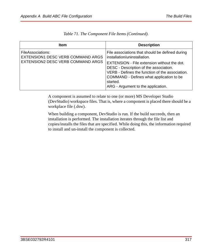
Appendix A Build ABC File Configuration The Build Files
A component is assumed to relate to one (or more) MS Developer Studio (DevStudio) workspace files. That is, where a component is placed there should be a workplace file (.dsw).
When building a component, DevStudio is run. If the build succeeds, then an installation is performed. The installation iterates through the file list and copies/installs the files that are specified. While doing this, the information required to install and un-install the component is collected.
FileAssociations:EXTENSION1 DESC VERB COMMAND ARGSEXTENSION2 DESC VERB COMMAND ARGS
File associations that should be defined during installation/uninstallation.
EXTENSION - File extension without the dot.DESC - Description of the association.VERB - Defines the function of the association.COMMAND - Defines what application to be started.ARG - Argument to the application.
Table 71. The Component File Items (Continued).
Item Description
3BSE032792R4101 317
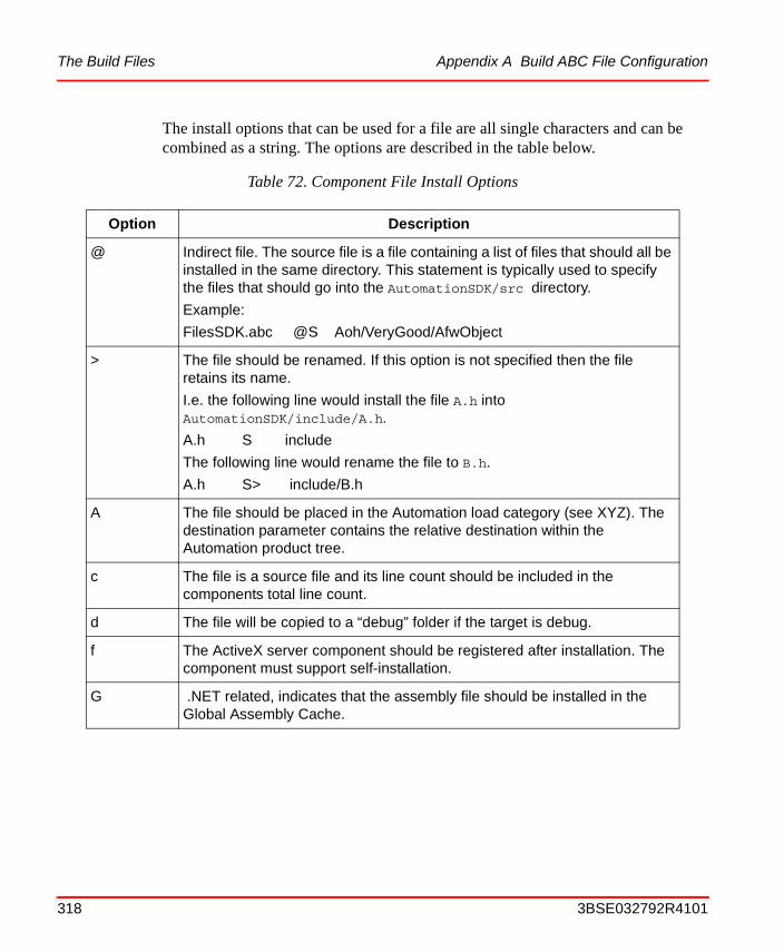
The Build Files Appendix A Build ABC File Configuration
The install options that can be used for a file are all single characters and can be combined as a string. The options are described in the table below.
Table 72. Component File Install Options
Option Description
@ Indirect file. The source file is a file containing a list of files that should all be installed in the same directory. This statement is typically used to specify the files that should go into the AutomationSDK/src directory.
Example:
FilesSDK.abc @S Aoh/VeryGood/AfwObject
> The file should be renamed. If this option is not specified then the file retains its name.
I.e. the following line would install the file A.h into AutomationSDK/include/A.h.
A.h S include
The following line would rename the file to B.h.
A.h S> include/B.h
A The file should be placed in the Automation load category (see XYZ). The destination parameter contains the relative destination within the Automation product tree.
c The file is a source file and its line count should be included in the components total line count.
d The file will be copied to a “debug” folder if the target is debug.
f The ActiveX server component should be registered after installation. The component must support self-installation.
G .NET related, indicates that the assembly file should be installed in the Global Assembly Cache.
318 3BSE032792R4101
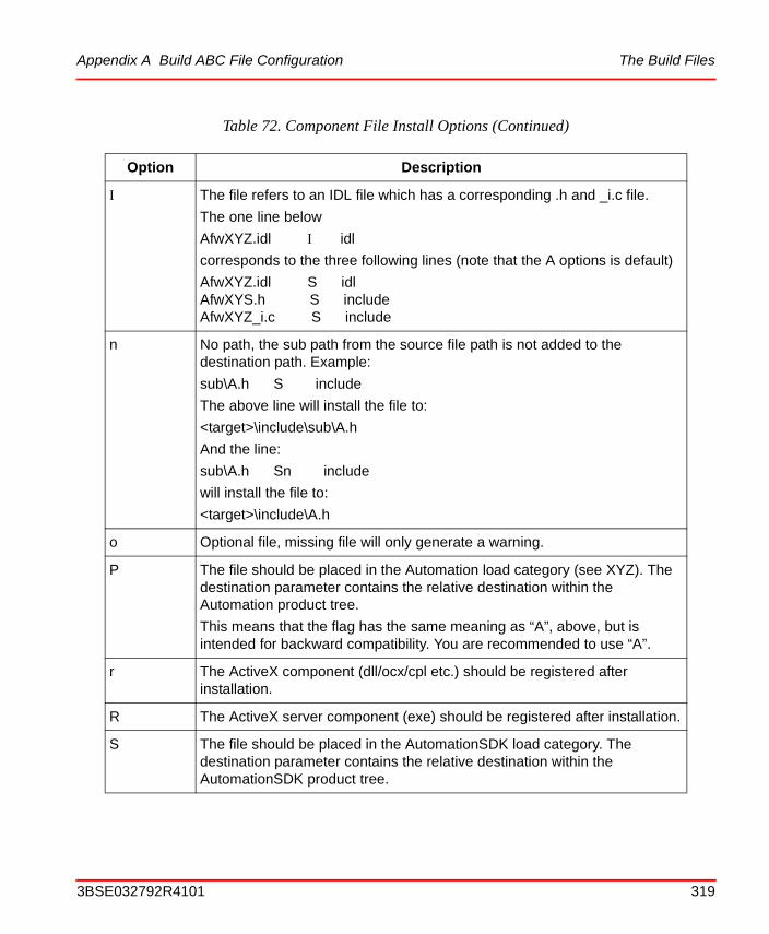
Appendix A Build ABC File Configuration The Build Files
I The file refers to an IDL file which has a corresponding .h and _i.c file.
The one line below
AfwXYZ.idl I idl
corresponds to the three following lines (note that the A options is default)
AfwXYZ.idl S idlAfwXYS.h S includeAfwXYZ_i.c S include
n No path, the sub path from the source file path is not added to the destination path. Example:
sub\A.h S include
The above line will install the file to:
<target>\include\sub\A.h
And the line:
sub\A.h Sn include
will install the file to:
<target>\include\A.h
o Optional file, missing file will only generate a warning.
P The file should be placed in the Automation load category (see XYZ). The destination parameter contains the relative destination within the Automation product tree.
This means that the flag has the same meaning as “A”, above, but is intended for backward compatibility. You are recommended to use “A”.
r The ActiveX component (dll/ocx/cpl etc.) should be registered after installation.
R The ActiveX server component (exe) should be registered after installation.
S The file should be placed in the AutomationSDK load category. The destination parameter contains the relative destination within the AutomationSDK product tree.
Table 72. Component File Install Options (Continued)
Option Description
3BSE032792R4101 319
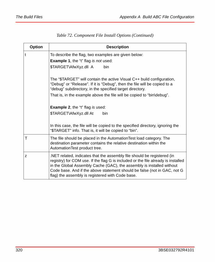
The Build Files Appendix A Build ABC File Configuration
t To describe the flag, two examples are given below:
Example 1, the “t” flag is not used:
$TARGET\AfwXyz.dll A bin
The “$TARGET” will contain the active Visual C++ build configuration, “Debug” or “Release”. If it is “Debug”, then the file will be copied to a “debug” subdirectory, in the specified target directory.
That is, in the example above the file will be copied to “bin\debug”.
Example 2, the “t” flag is used:
$TARGET\AfwXyz.dll At bin
In this case, the file will be copied to the specified directory, ignoring the “$TARGET” info. That is, it will be copied to “bin”.
T The file should be placed in the AutomationTest load category. The destination parameter contains the relative destination within the AutomationTest product tree.
z .NET related, indicates that the assembly file should be registered (in registry) for COM use. If the flag G is included or the file already is installed in the Global Assembly Cache (GAC), the assembly is installed without Code base. And if the above statement should be false (not in GAC, not G flag) the assembly is registered with Code base.
Table 72. Component File Install Options (Continued)
Option Description
320 3BSE032792R4101
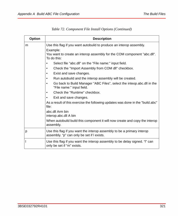
Appendix A Build ABC File Configuration The Build Files
m Use this flag if you want autobuild to produce an interop assembly.
Example:You want to create an interop assembly for the COM component "abc.dll". To do this:
• Select file "abc.dll" on the "File name:" input field.
• Check the "Import Assembly from COM dll" checkbox.
• Exist and save changes.
• Run autobuild and the interop assembly will be created.
• Go back to Build Manager "ABC Files", select the inteop.abc.dll in the "File name:" input field.
• Check the "Runtime" checkbox.
• Exit and save changes.
As a result of this exercise the following updates was done in the "build.abc" file:
abc.dll Arm bininterop.abc.dll A bin
When autobuild build this component it will now create and copy the interop assembly.
p Use this flag if you want the interop assembly to be a primary interop assembly. “p” can only be set if l exists.
l Use this flag if you want the interop assembly to be delay signed. “l” can only be set if “m” exists.
Table 72. Component File Install Options (Continued)
Option Description
3BSE032792R4101 321
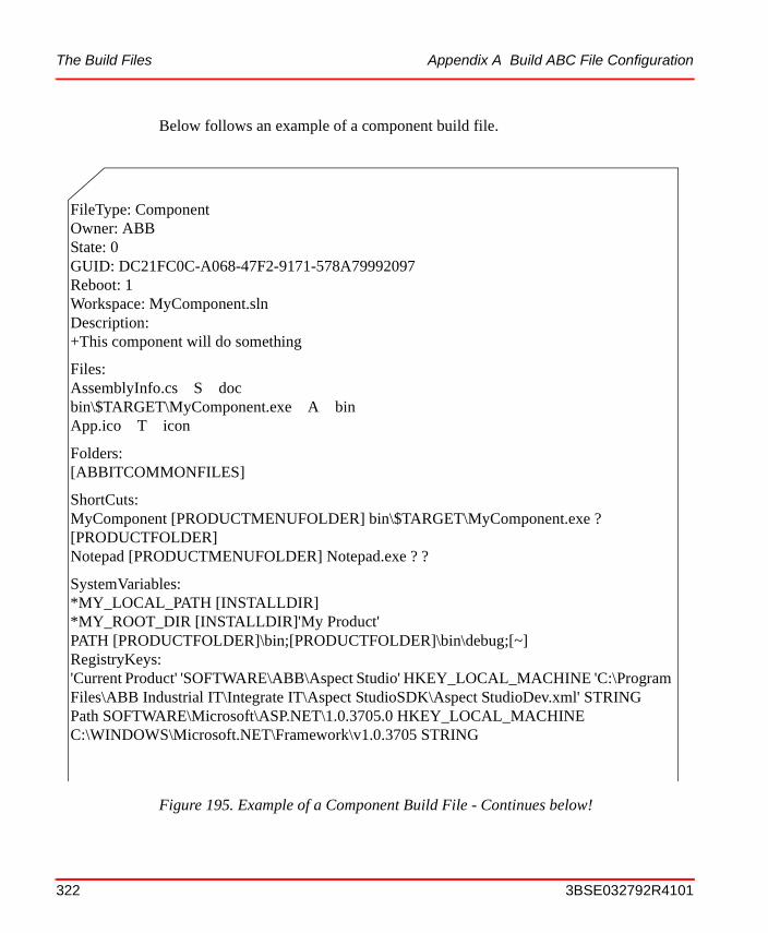
The Build Files Appendix A Build ABC File Configuration
Below follows an example of a component build file.
Figure 195. Example of a Component Build File - Continues below!
FileType: ComponentOwner: ABBState: 0GUID: DC21FC0C-A068-47F2-9171-578A79992097Reboot: 1Workspace: MyComponent.slnDescription: +This component will do something
Files:AssemblyInfo.cs S docbin\$TARGET\MyComponent.exe A binApp.ico T icon
Folders:[ABBITCOMMONFILES]
ShortCuts:MyComponent [PRODUCTMENUFOLDER] bin\$TARGET\MyComponent.exe ? [PRODUCTFOLDER]Notepad [PRODUCTMENUFOLDER] Notepad.exe ? ?
SystemVariables:*MY_LOCAL_PATH [INSTALLDIR]*MY_ROOT_DIR [INSTALLDIR]'My Product'PATH [PRODUCTFOLDER]\bin;[PRODUCTFOLDER]\bin\debug;[~]RegistryKeys:'Current Product' 'SOFTWARE\ABB\Aspect Studio' HKEY_LOCAL_MACHINE 'C:\Program Files\ABB Industrial IT\Integrate IT\Aspect StudioSDK\Aspect StudioDev.xml' STRINGPath SOFTWARE\Microsoft\ASP.NET\1.0.3705.0 HKEY_LOCAL_MACHINE C:\WINDOWS\Microsoft.NET\Framework\v1.0.3705 STRING
322 3BSE032792R4101
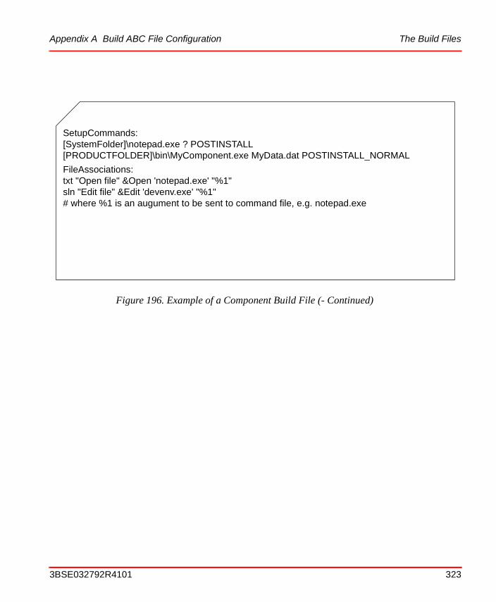
Appendix A Build ABC File Configuration The Build Files
Figure 196. Example of a Component Build File (- Continued)
SetupCommands:[SystemFolder]\notepad.exe ? POSTINSTALL[PRODUCTFOLDER]\bin\MyComponent.exe MyData.dat POSTINSTALL_NORMAL
FileAssociations:txt "Open file" &Open 'notepad.exe' "%1"sln "Edit file" &Edit 'devenv.exe' "%1"# where %1 is an augument to be sent to command file, e.g. notepad.exe
3BSE032792R4101 323
The Build Files Appendix A Build ABC File Configuration
324 3BSE032792R4101
Appendix B Strong Name in Aspect Studio
Assemblies are a fundamental part of programming with the .NET Framework. The implementation of supporting these techniques in the Aspect Studio (AS) tools is thus necessary. Support on Interoperability and Strong Name in Aspect Studio plays an essential part in building and distributing .NET based applications.
Strong Name and Interoperability
Strong Name
An assembly can be referenced by more then one application. This type of assemblies is referred as Shared Assemblies. In the concept of Shared Assemblies, strong name plays an important part, where a strong (shared) name is a simple text name accompanied by a version number, a public key, and a culture. If the intention is to share an assembly among several applications it's recommended to install the assembly in the global assembly cache (GAC). The GAC stores assemblies specifically designated to be shared by several applications on the computer. An assembly installed in the GAC must also have a strong name.
A shared assembly must therefore be signed with a strong name, which requires a public/private key pair. This public and private cryptographic key pair are used during compilation to create a strong-named assembly. You wouldn't create a new key pair with every assembly, but you'd have one in the company or for each product so the key uniquely identifies your product/company's assemblies.
The private key of a company should be safely stored. Just a few security people should typically have access to it. That's why the signature of an assembly can be added at a later time, such as before distribution. We use the term re-signing delay signed assemblies, where the assemblies are compiled with the correct private key pair when development is done and product is ready for shipping.
3BSE032792R4101 325
Interoperability Appendix B Strong Name in Aspect Studio
As a result a developer doesn't have access to the key pair but might also need to share assemblies by adding it to the GAC or by simply sharing it among applications. This problem is solved by using the Public keys. By delay signing your assemblies with your public key the problem is locally solved, this requires that the verification of a certain public key is turned off, when that is done the developer can do everything which can be done on a fully signed assembly.
Interoperability
Interoperability means overriding the bridge between the COM world and the .NET Framework. When using assemblies from COM it's necessary to add some data about the assembly in the registry. This is encapsulated in the AS tools, and is done via the Auto Builder, using flags in the build.abc file of the component. If the assembly isn't installed in the GAC or isn't intended to be installed (if build.abc file doesn't have an "add to GAC" flag) the assembly is automatically registered with code base; if the assembly is to be added to GAC, it's registered without code base.
Strong Name Requirements
The use of Strong Name requires:
• Creation of a Key Pair where a public key is extracted from.
• Verification turn-off for the local machine.
• A re-sign of delay signed assemblies.
• Add assembly to GAC.
• Register assembly to be used in COM.
• Remove assembly from GAC.
• Unregister assembly which is used in COM.
Strong Name and Interoperability in the Aspect Studio Tools
Now that we have some knowledge about the concepts of .Net assembly, we need to know how or where these functions are implemented in Aspect Studio.
326 3BSE032792R4101
Appendix B Strong Name in Aspect Studio Environment Setup Tool
To demonstrate these functions, a tutorial is developed and will guide you to go through the related tools, after tutorial, you will know the how to use strong name related functions in aspect studio.
Environment Setup Tool
When a new product is created using Environment Setup tool, a set of keys for the product will be automatically generated, i.e., a private key with a name of "KeyPair.snk" and a public key with a name of "Public.snk". Both private key and public key are placed in the folder: "\<ProductName>SDK\src\<ProductName>\Definition Files". The FileSDK.abc file in the folder is automatically updated with the addition of these two key files.
A copy of public key file: "Public.snk" is placed under "\<ProductName>SDK\" folder, in order to make a relative path consistent for all assemblies of the product, which needs delay signing.
1. Create a new product. Select a "basic product" template.
2. When creation is done set values for the new product.
3. Make sure that the keys exist in the location described above.
4. Set values.
5. Click on the Public Key Status to see if the public key verification was turned off.
Build Manager Tool
The Build Manager is primarily (regarding the use of strong name) used for editing build.abc files. To illustrate the use of the BM we need to set up projects to the product.
1. Create new folder (\src\FS\SM) in accordance with standard folder structure.
2. Create a new VS7 solution under the SM folder (a C# project is recommended).
This tutorial is not intended to give a guide to the usage of the aspect studio tools, it is concentrated on the use of strong name. For detail description of aspect studio, please refer to the user guide.
3BSE032792R4101 327

Build Manager Tool Appendix B Strong Name in Aspect Studio
3. Add a simple method to the C# project, which returns a simple string.
4. In the "AssemblyInfo.cs" file in the project, do following changes:
Change AssemblyAttributes below:
[assembly: AssemblyDelaySign(false)]
[assembly: AssemblyKeyFile("")]
To:
[assembly: AssemblyDelaySign(true)]
[assembly: AssemblyKeyFile(@"..\..\..\..\..\..\Public.snk")]
Thus, after building the project, the assembly is delay signed with the file Public.snk that is placed in the folder: <Product>SDK. After above changes, build the solution.
5. Use the Build Manager tool to edit the build.abc file of the project (Project Related/ABC Files).
a. Select the FS, SM the comp created in step 3.
b. Double click the comp and press "New" in the "Component Build File Definition" dialog.
c. From the "Edit File Settings" dialog open the "Browse Component Flag" dialog and add the created .dll under bin\debug. Close dialog.
d. From the "Edit File Settings" dialog select "Install Assembly to GAC" under "Miscellaneous".
e. Select "Register Assembly for COM".
328 3BSE032792R4101
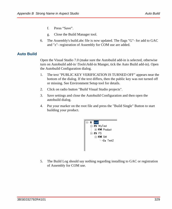
Appendix B Strong Name in Aspect Studio Auto Build
f. Press “Save”.
g. Close the Build Manager tool.
6. The Assembly's build.abc file is now updated. The flags "G"- for add to GAC and "z"- registration of Assembly for COM use are added.
Auto Build
Open the Visual Studio 7.0 (make sure the Autobuild add-in is selected, otherwise turn on Autobuild add-in \Tools\Add-in Manger, tick the Auto Build add-in). Open the Autobuild Configuration dialog.
1. The text "PUBLIC KEY VERIFICATION IS TURNED OFF" appears near the bottom of the dialog. If the text differs, then the public key was not turned off or missing. See Environment Setup tool for details.
2. Click on radio button "Build Visual Studio projects".
3. Save settings and close the Autobuild Configuration and then open the autobuild dialog.
4. Put your marker on the root file and press the "Build Single" Button to start building your product.
5. The Build Log should say nothing regarding installing to GAC or registration of Assembly for COM use.
3BSE032792R4101 329
Does it Work? Appendix B Strong Name in Aspect Studio
Does it Work?To see if the Assembly was added to GAC, do as follows:
1. Open the .NET Framework configuration (Start/Settings/Control Panel/Administrative Tools/Microsoft .NET Framework configuration) to confirm that the Assembly is there. (Look for the assembly name).
2. Instead of looking in the registry directly, starting a Visual basic 6 (VB6) project to test that the Assembly is properly registered. Create a Standard exe project in VB6 and attach the following code to a button:
Dim oo As Object
Set oo =CreateObject("<YourNameSpace>.<YourClassName>")
MsgBox oo.<YourMethodName>()
Run program anc click on the button. The string defined in the C# project should be returned.
330 3BSE032792R4101
Appendix B Strong Name in Aspect Studio Re-signing Assemblies
3. To remove the previously added assembly, do as follows:Open Autobuild Configuration dialog from Visual studio.Net (VS7).
a. Select the Uninstall option.
b. Save settings and close Autobuild Configuration.
c. Open the Autobuild dialog.
d. Put your marker on the root file and press the "Build Single" Button to uninstall products.
e. Repeat step 2 and 3 to see if the Assembly is removed from the GAC.
Re-signing AssembliesAs described in previous sections, developers can typically only access to the public key of a product, i.e. the assemblies are not properly signed, thus, the assembly needs to be re-signed with the private key pair before distribution. To re-sign a delayed signed assembly, do as follows:
1. Open the Autobuild configuration dialog.
2. Select the "Create Windows Installer MSM files" option (re-sign is done as the initial phase of the MSM build operation).
3BSE032792R4101 331
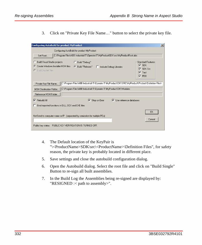
Re-signing Assemblies Appendix B Strong Name in Aspect Studio
3. Click on "Private Key File Name…" button to select the private key file.
4. The Default location of the KeyPair is "\<ProductName>SDK\src\<ProductName>\Definition Files", for safety reason, the private key is probably located in different place.
5. Save settings and close the autobuild configuration dialog.
6. Open the Autobuild dialog. Select the root file and click on "Build Single" Button to re-sign all built assemblies.
7. In the Build Log the Assemblies being re-signed are displayed by: "RESIGNED :< path to assembly>".
332 3BSE032792R4101
Appendix B Strong Name in Aspect Studio Create a Package of the Product for Distribution
Create a Package of the Product for DistributionThere are no changes in creating MSM and the creation of a distributable package of the product. An assembly to be added to the GAC will be added to GAC during installation and registered if it is intended to be registered for COM use. To create a package of the product, do as follows: (Refer the User Guide for a details on creating MSM and packaging from the Product Packager).
1. Create MSM via the AutoBuild.
2. Create a package from the Product Packager.
3. If installation is to be performed on the same PC, please remove the product and it's settings from the PC before installation.
4. Run the installation.
5. Check if assembly was added to GAC, and VB program is functioning.
ProblemsAs described above we generate a set of keys for each product when creating a new product. This is all fine but what if you want to use the same keys for every product in the company? Evidently Microsoft is said to only have one private key within their company used for signing assemblies. Also what if you have existing projects with no Keys and want to implement this in the future development of your products? And finally what if you're required to use other key names then the ones given from the Environment Setup Tool?
Same Keys - Different Products
The first problem is easily solved! Make up your mind of which set of keys you want to have, and just paste a copy of your selected public key ("public.snk") in the "<product>SDK" folder (delete first, or override old file). For your own sake do this procedure. Using a "top" folder where you keep your public key will make an already long path to long (in your project files), but of course, it is possible. If so, choose the key file from the Autobuild tool "public key path" button and choose selected file (instead of going for the default path). The private key shall be kept with restriction and only needed when re-signing delayed signed assemblies so it won't be any problem (since it's the intended way of doing it).
3BSE032792R4101 333
Old Products - No Keys Appendix B Strong Name in Aspect Studio
Just select the private key file when pressing the "private key path". It might be advised to delete the key files not used in your products.
Old Products - No Keys
The Second problem is also quite easy to solve, but it requires that you go "outside" the Aspect Studio tools. Typically these kinds of problem arise when an overall strategy regarding signing of assemblies is implemented in your organization. The possibility that there are existing products under construction are immediate, thus you need to adopt these existing products in accordance with the formality wanted by the AS tool, described above.
• Primarily we need a set of keys, you could of course create a new product and "steal" those keys and delete the project. This might not be the "cleanest" way of doing it though. The external creation of keys is done in the Strong Name tool which you access from: "Visual Studio .Net Command prompt" (Start/Programs/Microsoft Visual Studio .NET/Visual Studio .Net tools/Visual Studio .NET Command prompt). Use the following command in the prompt;
sn -k "\<ProductName>SDK\src\<ProductName>\Definition Files\KeyPair.snk"
The private key is created. Now extract the public key from the private key.
sn -p "\<ProductName>SDK\src\<ProductName>\Definition Files\KeyPair.snk" "\<ProductName>SDK\src\<ProductName>\Definition Files\Public.snk"
Both the KeyPair.snk and the Public.snk is now placed in the definition files folder.
• Do a copy (not cut) of the file "\<ProductName>SDK\src\<ProductName>\Definition Files\Public.snk" and paste it to the "\<ProductName>SDK" folder. (Thus two copies of public file).
• Turn the verification off by clicking on Set values button. The verification of the public.snk files need to be turned off.
– Open Environment Setup Tool and select your product. Click on Public Key Status, if it is not turned off press the "Set Values" button.
334 3BSE032792R4101
Appendix B Strong Name in Aspect Studio A Final Word
• To encapsulate the key files in a product deployment the .abc files in the "\<ProductName>SDK\src\<ProductName>\Definition Files" folder need to be updated. This can be done in the Build Manager Tool or by manually edit the files. Make the file build.abc file in the "\<ProductName>SDK\src\<ProductName>\Definition Files" folder look like this:
Public.snk S
And add the following text in FileSDK.abc in same folder as above
KeyPair.snk ?
Public.snk ?
New key pairs are created with static names (KeyPair.snk, Public.snk). The Aspect Studio tools expects these names and are developed to function with these names. Remember to update the .abc files in accordance with your new name setting if you want the keys to be included in distribution of the product.
The public key verification most likely needs to be turned off. Run the Environment Setup tool, the tool expects the public key to be named "Public.snk" and placed under "\<product>SDK", if the key file is not found, please redefine the public key path at the bottom of the Visual studio Directory Options list and then click on Set values button. The public key verification is now turned off and is ready to be used in other Aspect Studio tools such as AutoBuild.
A Final WordThis tutorial material has no ambition to decide or implement a certain method for handling the use of strong name keys. The Aspect Studio Tools only provide the necessary files and an embedded way of using the use of strong name and interoperability in the Aspect Studio Tools. However we do emphasize an implementation for an overall strategy particularly regarding the use of the private keys (KeyPair.snk) recommended (by Microsoft) to be handled with restrictions.
3BSE032792R4101 335

A Final Word Appendix B Strong Name in Aspect Studio
336 3BSE032792R4101
INDEX
AAdvSdtSoftwareBuilder 254Aspect Category 87Aspect Data 25Aspect Directory 27Aspect Express
introduction to 31Aspect Express Builder 31Aspect Express Packager 31Aspect Objects AppWizard 27
create a System Extension 88create an AfW Service 89create an Afw Test Project 89create an Aspect System 87introduction to 25the "Step 1 of 2" dialog box 86the "Step 2 of 2" dialog box 87the Location textbox 85what you can do with it 83
Aspect Page 25Aspect Studio user´s guide
introduction to 11Aspect System 25
introduction to 27Aspect Type 87Aspect Verb 25Aspect View 25ATL Object Wizard
add an Aspect Data ASO 91add an Aspect Page ASO 102add an Aspect Verb ASO 103add an Aspect View ASO 100introduction to 90
AutoBuildconfigure AutoBuild 200
build Visual Studio projects 200create Windows Installer MSM files 203
how to set up the AutoBuild add-ins 198introduction to 197run AutoBuild 207
Bbaseline 29Build Manager
getting started 106introduction to 29, 105the Project Related tab 136
Find GUID Collisions 141Make FilesSDK 139
the Scheduler Related tab 165the VSS Related tab 115tutorial (Set label, Create Baseline, and Get
Latest) 107user interfaces (GUIs) 111what you can do with the Build Manager 105
build.abc file 45
Cclient 28Component 45
Ddistribution 29
EEnvironment Setup
edit the .ini file 77Environment Variables 71
3BSE032792R4101 337
IndexIndex
Forced 73getting started 58introduction to 24paths 73tutorial 59user interfaces (GUIs) 64what you can do with the tool 57
error messagesProduct Packager 303
FFiles report 300FSSupport system module
build tree, an illustration 305component level 305development structure 306functional subsystem level 305root level 305system module level 305the Work, Baselines and Releases projects 306
Functional Subsystem 45
Iinstallation
change the current installation 40choose the features (tools) to be installed 39how to install from a CD or a server 35logging of 36re-installation 40un-installation 40verification 42
MMicrosoft Windows Installer 29MS Visual Studio 29MS Visual Studio project 26MSI 29
Ooperation
getting started 58, 106, 222
Pproduct distribution
installation of 256product name 60product overview 21Product Packager 27
getting started 213, 222introduction to 29turorial, creation of a product distribution 222tutorial, creation of a service pack 237, 248user interfaces (GUIs) 268
the Product Packager main dialog 268the Project Settings dialog box 271 to 272the Service Pack Builder user
interface 288what you can do with the Product
Packager 217working procedures 255
AdvSdtMSMBuilder 255an oveview illustration 256create a service pack 259creation of a distribution in batch
mode 254install a service pack 259install, re-install and un-install a
distribution 256installation via Internet 257Product Installation dialog 259 to 260silent installation 258the Add/Remove program icon in the
Control Panel 257product scope 22product template 59Product Viewer
getting started 293introduction to 30user interfaces (GUIs) 295
338 3BSE032792R4101 338 3BSE032792R4101
Index
what you can do with the Product Viewer 293working procedure 294
protocol 28Protocols 25
RRelease
new in this release 31
Sscript 29server 25, 28Service 25Service Pack Builder
introduction to 30Simple Server
introduction to 28socket protocol 28Socket Server
introduction to 28start-up and shut-down procedures 41System Extension 25
introduction to 27System Module 45System Product Extension 27
TTest Project 25
introduction to 28training courses 21
UUnicode 26
VVisual Source Safe 29Visual Studio project 26
WWinsocket 28work flow examples
adding a new System Extension Component 47
build of a product version 52introduction to 47prerequisites for 47
3BSE032792R4101 339
IndexIndex
340 3BSE032792R4101 340 3BSE032792R4101

3BSE032792R4101. Printed in Sweden June 2005Copyright © 2003-2005 by ABB. All Rights Reserved® Registered Trademark of ABB.™ Trademark of ABB.
Automation Technology ProductsMannheim, Germanywww.abb.de/controlsystems
Automation Technology Products Wickliffe, Ohio, USAwww.abb.com/controlsystems
Automation Technology ProductsVästerås, Swedenwww.abb.com/controlsystems
http://www.abb.com