Artificial Reversible Skin (ARES) · PDF fileArtificial Reversible Skin (ARES) ... 2.2.4...
78
i Artificial Reversible Skin (ARES) A Major Qualifying Project Report: Submitted to the Faculty of the WORCESTER POLYTECHNIC INSTITUTE in partial fulfillment of the requirements for the degree of Bachelor of Science in Mechanical Engineering by Gregory Andujar Mechanical Engineering Duje Jalaska Mechanical Engineering Jonathan Ng Mechanical Engineering Chris Rimchala Mechanical Engineering Cullen O’Brien Mechanical Engineering MIRAD Laboratory, April 30, 2013 Approved Professor Mustapha S. Fofana, Advisor Director of Mirad Laboratory, Mechanical Engineering Department
-
Upload
vuongkhuong -
Category
Documents
-
view
216 -
download
1
Transcript of Artificial Reversible Skin (ARES) · PDF fileArtificial Reversible Skin (ARES) ... 2.2.4...

i
Artificial Reversible Skin (ARES)
A Major Qualifying Project Report:
Submitted to the Faculty of the
WORCESTER POLYTECHNIC INSTITUTE in partial fulfillment of the requirements for the degree of
Bachelor of Science
in
Mechanical Engineering
by
Gregory Andujar
Mechanical Engineering
Duje Jalaska
Mechanical Engineering
Jonathan Ng
Mechanical Engineering
Chris Rimchala
Mechanical Engineering
Cullen O’Brien
Mechanical Engineering
MIRAD Laboratory, April 30, 2013
Approved
Professor Mustapha S. Fofana, Advisor
Director of Mirad Laboratory, Mechanical Engineering Department

ii
Abstract The objective of this MQP project is to demonstrate the feasibility of engineering
virtual anatomical consciousness (EVACU) patients that mimic world-class realistic patient
simulation for a broad spectrum of diagnosis, care, treatment and patient situational
responses with respect to stimulus or perturbations. An adaptable system for the skin, that
is capable of displaying color changes in the skin similar to human physiology caused by
controlled perturbations is created and developed. The system encompasses organic light
emitting diode (OLED) displays that are implanted underneath the silicone rubber skin of
the mannequin. After performing fatigue analysis and constructing a proof of concept, it is
shown that the use of strategically placed OLED displays could realistically simulate
physiological skin changes under controlled perturbations. However, for this project, the
team could not procure any flexible OLED displays as the manufacturer of this technology
ran into production issues and will not be available until December of 2013. The proposed
design will serve as a framework to medically simulate a range of reversible physiological
changes of conscious and unconscious patients under controlled perturbations.

iii
Table of Contents Abstract .............................................................................................................................................................. ii
Table of Contents ........................................................................................................................................... iii
List of Figures ....................................................................................................................................................v
Acknowledgements ...................................................................................................................................... vii
CHAPTER 1: IMPROVING MEDICAL SIMULATION ................................................................ 1 1.1 Introduction .................................................................................................................................................... 1
CHAPTER 2: THE WORLD OF SIMULATION ............................................................................. 3 2.1 Simulation in Modern Society ................................................................................................................. 3
2.1.1 Simulation in Transportation ......................................................................................................... 3 2.1.2 Simulation in Weather ....................................................................................................................... 7 2.1.3 Simulation in Military ...................................................................................................................... 10
2.2 Simulation in NASA ................................................................................................................................... 12 2.2.1 NASA Ames Research Center ....................................................................................................... 12 2.2.2 Vertical Motion Simulator ............................................................................................................. 13 2.2.3 FutureFlight Central ........................................................................................................................ 14 2.2.4 Crew-Vehicle Systems Research Facility ................................................................................. 15
2.3 Medical Simulation ................................................................................................................................... 16 2.3.1 SimMan 3G ........................................................................................................................................... 16 2.3.2 Surgical Chloe ..................................................................................................................................... 19 2.3.3 SynDaver Synthetic Human .......................................................................................................... 21 2.3.4 Strategic Operations Cut-Suit ....................................................................................................... 22 2.3.5 STRATUS Medical Simulation Technologies .......................................................................... 23
2.3.5.1 Da Vinci System ............................................................................................................................................. 23 2.3.5.2 CAE Healthcare LapVR ............................................................................................................................... 26 2.3.5.3 CAE Healthcare VIMEDIX .......................................................................................................................... 29 2.3.5.4 Medsimulation SIMANTHA ...................................................................................................................... 30 2.3.5.5 Immersion Medical AccuTouch Endoscopy Simulator ................................................................ 31 2.3.5.6 Laerdal LMA Baby ........................................................................................................................................ 32 2.3.5.7 Laerdal SimBaby ........................................................................................................................................... 33
2.4 Artificial/Synthetic Skin ......................................................................................................................... 34 2.4.1 Properties of Human Skin ............................................................................................................. 35 2.4.2 Environmental Effects on Human Skin .................................................................................... 37 2.4.3 Skin Reaction to Chemicals ........................................................................................................... 39
2.5 Technologies Investigated for potential Integration .................................................................. 40 2.5.1 Fiber Optic Cables ............................................................................................................................. 40 2.5.2 Organic Light Emitting Diodes (OLEDs) .................................................................................. 41 2.5.3 Polymerized Crystalline Colloidal Array ................................................................................. 42 2.5.4 Silicone Molding Gel ......................................................................................................................... 43

iv
CHAPTER 3: VIRTUAL HUMAN SKIN ........................................................................................ 45 3.1 Motivation .................................................................................................................................................... 45 3.2 Objectives and Goals ................................................................................................................................ 45 3.3 Methodology ................................................................................................................................................ 46 3.4 Task Specification...................................................................................................................................... 50 3.5 Preliminary Design ................................................................................................................................... 50
3.5.1 Fatigue Analysis ................................................................................................................................. 50 3.5.2 Prototype Construction: Silicone and Housing Process .................................................... 51
CHAPTER 4: CONCLUDING REMARKS ..................................................................................... 56
REFERENCES ........................................................................................................................................ 58
APPENDICES ......................................................................................................................................... 62 Appendix A: STRATUS Center Pictures .................................................................................................... 62 Appendix B: Silicone Rubber Compounds .............................................................................................. 66 Appendix C: Housing Parts Drawings ....................................................................................................... 67

v
List of Figures Figure 1: Pedestrian traffic simulation ............................................................................................................ 5
Figure 2: Air traffic simulation ............................................................................................................................ 6
Figure 3: Weather Simulation of a low-pressure system ......................................................................... 7
Figure 4: Simulation of oceanic surface current .......................................................................................... 9
Figure 5: Military vehicle simulator ............................................................................................................... 10
Figure 6: FreeMan Combat Trainer ................................................................................................................ 11
Figure 7: (a) Short-Takeoff/Vertical-landing Fighter, (b) Helicopter, (c) Space Shuttle, and (d) The Tiltrotor [3] .................................................................................................................................... 13
Figure 8: FutureFlight central tower cap ..................................................................................................... 14
Figure 9:(a) Boeing 747-400 simulator (b) Advanced concept flight simulator ......................... 15
Figure 10: SimMan 3G by Laerdal ................................................................................................................... 17
Figure 11: SimMan 3G .......................................................................................................................................... 18
Figure 12: Surgical Chloe .................................................................................................................................... 19
Figure 13: SynDaver synthetic human .......................................................................................................... 21
Figure 14: Cut suit ................................................................................................................................................. 22
Figure 15: Da Vinci Surgical System .............................................................................................................. 23
Figure 16: Da Vinci Surgical System at STRATUS ..................................................................................... 24
Figure 17: 3D HD Vision ...................................................................................................................................... 25
Figure 18: Above-Robotic instruments working inside the body, Below-Surgeon´s hands operating the EndoWrist controls ........................................................................................................ 26
Figure 19: CAE´s LapVR System ...................................................................................................................... 26
Figure 20: Performing an appendectomy using LapVR ......................................................................... 27
Figure 21: VIMEDIX Ultrasound System ...................................................................................................... 29
Figure 22: SIMANTHA Endovascular Simulator ....................................................................................... 30
Figure 23: AccuTouch Endoscopy Simulator ............................................................................................. 31

vi
Figure 24: (Left) Infant Laryngeal Mask Airway module, (Right) Dr. Pozner Demonstrating its Function ..................................................................................................................................................... 32
Figure 25: (Left) SimBaby with components, (Right) SimBaby during Simulation ................... 33
Figure 26: Stanford´s artificial silicone skin ............................................................................................... 34
Figure 27: Human skin stress-strain curve ................................................................................................. 36
Figure 28: Chemical burn example ................................................................................................................. 40
Figure 29: Examples of fiber optic applications ....................................................................................... 41
Figure 30: Breakdown of a OLEDs structure .............................................................................................. 42
Figure 31: The structure of a PCCA network .............................................................................................. 43
Figure 32: Silicone gel being poured to set ................................................................................................. 44
Figure 33 Methodology diagram ..................................................................................................................... 46
Figure 34: OLED SN curve .................................................................................................................................. 51
Figure 35: Prototype ............................................................................................................................................ 52
Figure 36: Silicone thickness testing device. .............................................................................................. 53
Figure 37: Silicone rubber thickness test sheets with and without pigment ............................... 53
Figure 38: Housing ................................................................................................................................................ 54
Figure 39: SimMan 3G™ ...................................................................................................................................... 62
Figure 40: Arm of SimMan 3G™ ....................................................................................................................... 62
Figure 41: SimMan 3G™ Work Station .......................................................................................................... 63
Figure 42: Infant incubation simulator ........................................................................................................ 63
Figure 43: SimBaby™ ............................................................................................................................................ 64
Figure 44: CAE’s LapVR Laparoscopy Simulator ...................................................................................... 64
Figure 45: SimMan medical simulator .......................................................................................................... 65
Figure 46: Dragon Skin 20 Silicone Rubber Compounds ...................................................................... 66

vii
Acknowledgements We would like to acknowledge Professor Mustapha Fofana for giving us the
opportunity to explore topics in Medical Simulation and for his help in narrowing
down our project goals. We would also like to acknowledge Dr. Charles Pozner for
giving us the opportunity to work with him on this project and for his knowledge of
medical simulation he has shared with us. Finally, we would like to acknowledge our
fifth team member, Gregory Andujar, who is a graduate student that worked on this
project for the partial fulfillment for his Master of Science degree.

1
CHAPTER 1: IMPROVING MEDICAL SIMULATION
1.1 Introduction As new doctors and other medical specialists transition to full time practitioners
there is a need for them to build on their academic knowledge with real world application.
And medical simulation is exactly the buffer that is needed to achieve those very necessary
skills without harming a patient. These proficiencies include teamwork and practice to
become competent. Though the current state of medical simulation has done a more than
adequate job of preparing medical practitioners to perform, there is always room to further
develop the current technology to add to the hands on learning experience of medical
simulation. Thus the development of a virtually artificial skin with reversible color changes
under typical perturbations is proposed. The design proved to be feasible and should not
fail under circumstances it would normally encounter.
This project aims to increase the effectiveness and realism of medical simulation
mannequins. When diagnosing live patients doctors rely on physiological changes of the
skin to provide information on patient condition. The mannequins used for training
however have skin that does not change under any circumstances, forcing doctors to rely
on only sensors and monitors to aid in diagnosis. In order to create a skin that displays
physiological changes typical of human skin, a design was developed that uses organic light
emitting diodes (OLED) underneath a silicone rubber coating. Theoretical analysis was
done on the design to ensure that forces encountered during simulation (such as chest
compressions and accidental falls) will not cause the OLED screens to fail. Finally a proof
2
of concept was developed in order to show that the display technology would realistically
exhibit changes that human skin undergoes. The design proved to be feasible and should
not fail under circumstances it would normally encounter.
The rest of the paper is sectioned as follows. Chapter 2 gives an overview of the
simulation technology spanning several areas pertinent to the project as well as other
relevant technology and information. Chapter 3 discusses the implementation method of
the work done to describe and explain the project results and observations. Chapter 4
discusses future work and concludes the paper.

3
CHAPTER 2: THE WORLD OF SIMULATION
2.1 Simulation in Modern Society Simulation is defined as, “the imitation of the operation of a real-world process or
system over time” [1]. In order to have a simulation, a model is first needed. The model
identifies the system to be simulated. This is because the simulation is looking at the
operation of the model over time. Some of the uses for simulation are to optimize
performance for modern technology, teach and hone skills for real world applications, as
well as test different scenarios. This is important because simulation can produce accurate
outcomes that will benefit a given field by providing useful data that could have been costly
or dangerous to obtain, or provide data for a new design that has not been built yet. The
biggest flaw for simulation comes from the fact that acquiring a legitimate source of
information can be difficult as this information dictates the characteristics and behaviors of
the model [2]. Various approximations and assumptions have to be used to complete a
simulation, and because of the nature of approximations and assumptions, the simulation’s
results can potentially deviate from the actual result.
2.1.1 Simulation in Transportation
Besides having simulation in medical applications, there can also be benefits to
other areas as well. One of those areas where simulation can improve the infrastructure is
in transportation [3]. Starting over forty years ago, transportation simulation is used to
design new routes of travel or monitor and evaluate the performance of the transportation
infrastructure being simulated [4]. Simulation is useful in transportation because

4
simulating traffic conditions using analytical or numerical methods can be tedious and time
consuming to the point where it is too complicated to use those methods. In addition,
simulation can produce a visual representation with clear details of the system over time,
whereas analytical or numerical methods can only show quantitative relationships [5].
That is why simulation in transportation uses mathematical models to simulate traffic
conditions in various scenarios.
To create a transportation simulation, particularly traffic simulation, a traffic model
needs to be selected. A traffic model is basically a methodology of performing the
simulation, which includes the numerical methods, probability and statistics, or theories
relevant to the model. Some of these traffic models include the Monte Carlo method, which
was one of the earliest models of simulation. This method utilized a discrete random
number series to create traffic conditions [6]. The Monte Carlo method is useful when
there are significant uncertainties within inputs and in systems where there are a large
number of coupled degrees of freedom [7]. However, when an input and output trajectory
are needed within a time interval, continuous-time simulation methods should be used
instead. The continuous models track the response of a system model over time by way of
differential equations [8].
Some of the applications for transportation simulation are ground transportation,
railway transportation, oceanic transportation, and air transportation. For ground
5
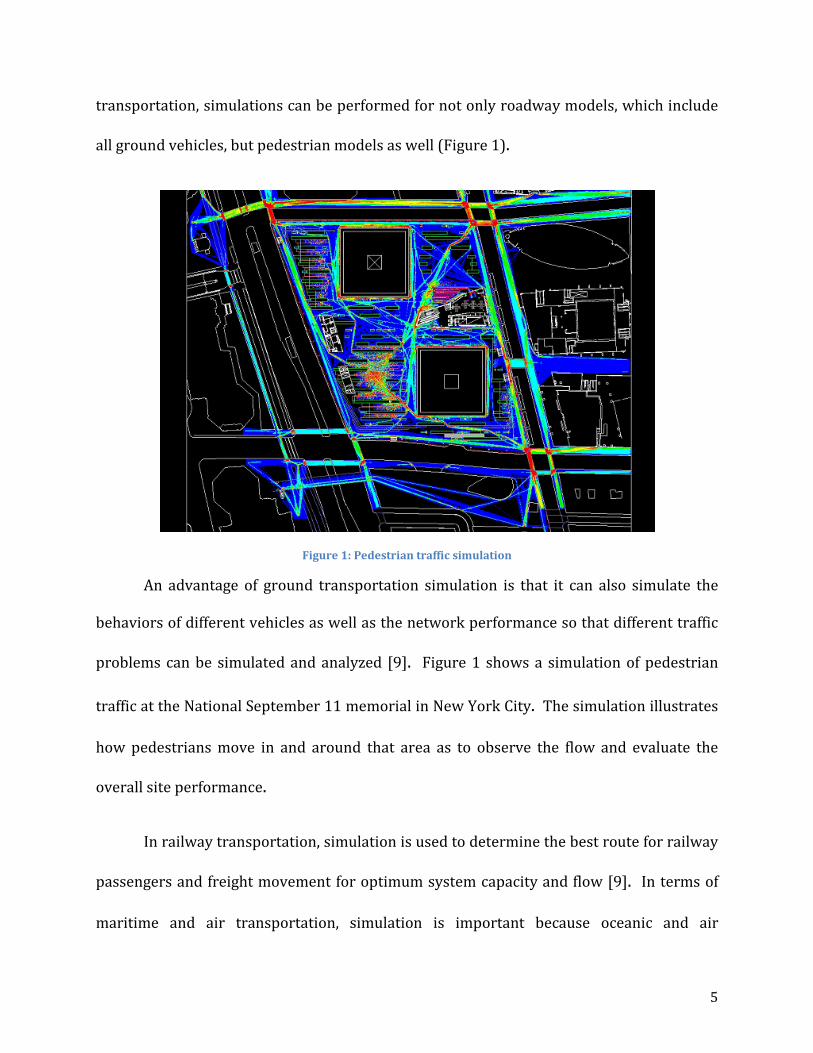
transportation, simulations can be performed for not only roadway models, which include
all ground vehicles, but pedestrian models as well (Figure 1).
Figure 1: Pedestrian traffic simulation
An advantage of ground transportation simulation is that it can also simulate the
behaviors of different vehicles as well as the network performance so that different traffic
problems can be simulated and analyzed [9]. Figure 1 shows a simulation of pedestrian
traffic at the National September 11 memorial in New York City. The simulation illustrates
how pedestrians move in and around that area as to observe the flow and evaluate the
overall site performance.
In railway transportation, simulation is used to determine the best route for railway
passengers and freight movement for optimum system capacity and flow [9]. In terms of
maritime and air transportation, simulation is important because oceanic and air
6
transportation is important to the economy. Maritime transportation includes all of the
barges that contain countless numbers of large shipping containers, which is where the
simulation is utilized. All of these shipping containers need to be kept track of, thus the
shipping containers are simulated in “container terminal modeling.” The model determines
the logistics of moving shipping containers for optimal system efficiency.
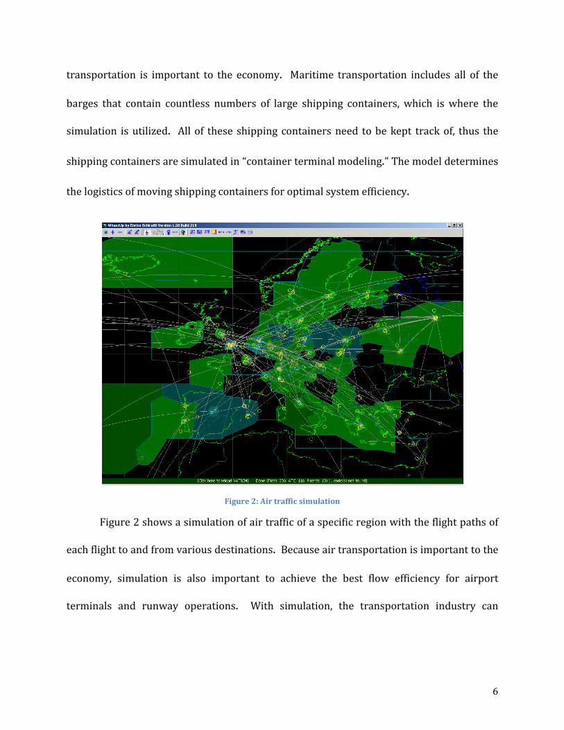
Figure 2: Air traffic simulation
Figure 2 shows a simulation of air traffic of a specific region with the flight paths of
each flight to and from various destinations. Because air transportation is important to the
economy, simulation is also important to achieve the best flow efficiency for airport
terminals and runway operations. With simulation, the transportation industry can

7
optimize its infrastructure to be faster and more efficient without having to spend money
on additional transportation implementations that are not optimized.
2.1.2 Simulation in Weather
The first attempt of weather prediction was in the 1920’s, but realistic predictions
were not achieved until computer simulation was invented in the 1950’s. Simulation in
weather, similar to transportation simulation, utilizes mathematical models to predict
weather. To simulate weather, data is taken from the Earth’s atmosphere and oceans via
weather satellites and input into forecast models similar to Figure 3. There are various
forecast models that are run all around the world that try to predict the weather both
regionally and globally [11].
Figure 3: Weather Simulation of a low-pressure system

8
Above is a depiction of a low-pressure system simulation. Weather simulation can
also be used for air quality purposes. This is important because being able to foretell if the
air quality for a given area would potentially be hazardous to the indigenous population
could prevent these airborne pollutants from harming the population. To simulate air
quality, several different variables need to be used. These variables include the velocity of
movement, the diffusion of the particles in the air, chemical transformation, and the ground
deposition of particles on the ground surface. However, to determine the velocity and
diffusion, the atmospheric fluid flow is required. A simulation model like the one above
involves the use of, “a set of equations, known as the primitive equations, used to predict
the future state of the atmosphere” [12]. From the use of these equations, including the
ideal gas law, all of the variables in the model can be simulated with respect to time to
achieve a weather prediction result. Some of the variables in the model include the density,
pressure, and air velocity of the atmosphere. The process of weather simulation takes the
previously mentioned set of equations, and uses them to find the rate of change for each of
the variables for the atmosphere in the simulation model. This rate of change predicts the
weather after a time step, or a given certain amount of time. The rate of change found is
then applied to the new atmospheric model to find the new rate of change for each variable
over another time-step.
Another aspect of weather simulation is the simulation of oceanic waves and wind.
Figure 4 is an illustration of the wind and wave current of the North Atlantic Ocean.

9
Simulations like these are important to wave dynamics because the top layer, or surface, of
the ocean is the most integral portion of wave dynamics [13]. When wind blows along the
surface of a body of water, there is a transfer of energy into the body of water, which
dictates how the surface reacts, as shown in Figure 4. The simulation results simulate,
“…wave generation, wave movement (propagation within a fluid), waves
shoaling, refraction, energy transfer between waves, and wave dissipation” [14].
Figure 4: Simulation of oceanic surface current
Since wind plays a fundamental role in this simulation, this model also uses other
weather prediction models to supply data, from the atmosphere, for the wind that blows
over the surface of the body of water. This allows for a more accurate prediction of oceanic
surface behavior as well as calculating the loss of energy from the whitecaps of waves and
the resonance between the waves [15].

10
2.1.3 Simulation in Military
Simulation has always been an essential component of the military since they have
been involved in virtual reality almost since its creation [15]. The military has also greatly
improved virtual reality technology by helping to develop new technologies and applying
them in the training of military personal. Today, the military has some form of simulation
for almost everything they own, whether it is vehicles, various equipment, weaponry, or
even different military scenarios (Figure 5).
Figure 5: Military vehicle simulator
Figure 5 is an image of a military Stryker armored vehicle simulator. While driving
a vehicle may seem straight forward, the fact of the matter is military vehicles tend to be
very large and behave differently than smaller vehicles. With modern warfare often taking
place in urban environments, maneuvering a bulky vehicle can become difficult [16].

11
Therefore, learning how to operate the vehicle efficiently is essential to military operations
in warzones because vehicles transport supplies and troops. If the vehicles cannot reach
their destination due to lack of vehicle operation skill, then this delay can cause
consequences to the military efficiency. Even though the above simulator costs roughly
800 thousand dollars, the actual vehicle can cost over one million dollars. In addition, the
vehicle operator will not only hone skills, but also not risk his or her own safety to do so.
Vehicles are not the only simulation the military has. There are also simulations for
their military combat scenarios. One company that makes military simulators is Virtual
Simulation Systems. One of their products is the FreeMan Combat Trainer shown in Figure
6 [17].
Figure 6: FreeMan Combat Trainer

12
The FreeMan Combat Trainer is a head worn virtual simulator that utilizes the
user’s movement as inputs for the simulator. Basically, whatever the user does will be
shown through the optics of the virtual simulator. This allows the user to move freely
while the virtual reality interface provides the virtual environment and given scenario. The
FreeMan Combat Trainer system can interact with eight users at one time. There is also
the option of linking several FreeMan Combat Trainer systems together for larger military
simulations [16]. The system itself is helmet mounted, meaning that the virtual simulator
will attach to a soldier’s standard issue helmet without issues, a 1280 pixel by 1024 pixel
high definition display, but most importantly, the system has six degrees of freedom, which
means the virtual simulator can simulate motion in all directions, allowing the virtual
simulator to react with the user in real time [16]. Simulation is important in military
applications because simulations provide the most realistic experience without the high
cost and danger of actual military operations.
2.2 Simulation in NASA
2.2.1 NASA Ames Research Center The NASA Ames Research Center is considered to be the world leader in thermal
protection systems, information technology, nanotechnology, biotechnology, fundamental
space biology, and human research. It was established in 1939 as the second laboratory of
the National Advisory Committee for Aeronautics. And after the formation of The National
Aeronautics and Space Administration (NASA), it was renamed the NASA Ames Research
Center [18]. The research center consists of many projects and laboratories; each is

13
dedicated to its own field of study. For instance, the Virtual Airspace Simulation
Technologies (VAST) Project tests revolutionary aeronautics concepts in order to select the
most beneficial. New concepts are tested through real time modeling and simulations to
guarantee the human performance. Human factor studies will provide a better
understanding of the human and system interactions [19].
2.2.2 Vertical Motion Simulator The Vertical Motion Simulator (VMS) is a high-fidelity simulator that provide highly
realistic flight characteristic of an aircraft. It has the capabilities to simulate both aircraft
and spacecraft. Figure 7 shows some of the vehicles that had been simulated, which include
Short-Takoff/Vertical-Landing Fighter, helicopters, Space Shuttle, and the Tiltrotor.
Figure 7: (a) Short-Takeoff/Vertical-landing Fighter, (b) Helicopter, (c) Space Shuttle, and (d) The Tiltrotor [3]
The VMS has the greatest motion range of any flight simulators in the world. It can
travel 60 feet vertically, 40 feet horizontally, 20 feet left to right, and 25 degrees of roll,
pitch and yaw. Furthermore, the cabin is highly customizable. The interior can be modified
to represent the cockpit of any aerospace vehicles. The simulator is equipped with
monitors that display out-of-window-graphics to represent the outside world for the pilots.
The computer-generated graphics can project 3-dimensional models of many geographical
(a)
(b)
(d)
(c)

14
locations, as well as aircrafts, ground vehicles, and buildings. It also has the ability to
simulate various weather and light conditions to represent real-life situations. The VMS is
integrated with the FutureFlight Central (FFC) and the Crew-Vehicle System Research
Facility (CVRSF) through the VAST Project to provide simultaneous cockpit and air traffic
control perspectives [20].
2.2.3 FutureFlight Central
The FutureFlight Central (FFC) a simulator for air traffic control management. The
two-story facility offers full-scale, 360-degree view of an airport, where controllers, pilots,
and airport personnel partake to evaluate new technologies and optimize procedures. Its
twelve projection screens provide a detailed, 3-dimensional, out-the-window view of the
airport (Figure 8).
Figure 8: FutureFlight central tower cap
The FFC has a database of over 100 aircraft model and ground vehicle models. It is
integrated with the VAST simulators, which means that they can all communicate with each

15
other while running simultaneous simulations to provide cockpit and air traffic control
perspectives. The FFC also use pseudo-pilots to represent aircrafts and ground vehicles.
The pseudo-pilots use computer software to “operate” a vehicle, which display many
aspects of aircraft movements in the FFC air traffic control room. Researchers can record
and analyze all simulation runs to further improve current technologies [21].
2.2.4 Crew-Vehicle Systems Research Facility The Crew-Vehicle Systems Research Facility (CVSRF) is a part of VAST, which tests
and evaluates new flight systems, as well as providing researchers with an environment
where they can study how and why aviation errors occur, especially human factor errors.
The CVSRF houses two high-fidelity flight simulators and its own air traffic control,
therefore the CVSRF is capable of simulating full-missions. Like the other simulators in the
VAST, this facility can also interact with the FFC and the VMS.
Figure 9:(a) Boeing 747-400 simulator (b) Advanced concept flight simulator
(a) (b)

16
The CVSRF include the Boeing 747-400 simulator (Figure 9a) and the Advance
Concepts Flight Simulator (ACFS) (Figure 9b). The Boeing 747-400 simulator is a fully
detailed replica of the Boeing 747 flight deck; all instruments, controls, and switches
operate in the same manner as the actual aircraft. The ACFS can model and simulate the
newest aircrafts models being built today. It is also highly customizable, similar to the VMS,
to represent a wide range of aircraft models. Both simulators have six-degrees-of-freedom
that provides pilots with flight characteristics, highly accurate to real-time. The CVSRF
simulator has a database, which can virtually display detailed representations of major
airports around the United States [22].
2.3 Medical Simulation The third and final topic studied was Current Medical Simulation. The simulation
mannequins on today’s market range vastly both in their abilities to simulate human traits
and in price. From around $125 [23] to over $45,000 [24], these devices have been
designed to simulate many different situations and train medical professionals all over the
world.
2.3.1 SimMan 3G
One of the most common simulation mannequins is the standard CPR simulator.
These are used by CPR certification courses around the world. Many people have been
exposed to these basic simulators. The cost of such instrument is only about $150, which
consists of nothing more than silicone skin, a tilting head, an expanding ribcage, and an air
bag to simulate the lungs. However, products like the SimMan™ (Figures 10 and 11) are

17
sophisticated enough that they are slowly being integrated into professional medical
training for doctors, nurses and EMTs [25].
Figure 10: SimMan 3G by Laerdal
The SimMan™, shown in Figures 10 and 11, is so advanced that it can bleed
realistically when lacerated, speak, secrete liquid, and has a human-like range of motion
[26]. The mannequin also has the ability to display vital signs. This includes a pulse that
can be felt in multiple locations as well as chest that rises and falls as it inhales and exhales.
In addition, the mouth and eyes open and close, and the pupils can dilate. These functions
are managed within the mannequin by a series of pumps and motors that move the fluid
and various mechanical components necessary to recreate these human features.

18
Figure 11: SimMan 3G
All of the mechanicals are in the torso, and the upper thighs have fluid reservoirs for
simulated blood and other various bodily fluids. This is all concealed underneath a
synthetic skin that can be removed. This skin has the ability to be punctured by needles to
simulate drug delivery protocol. The vital signs of the mannequin are displayed on the
equipment similar to what would be found in a hospital. Since the dummy uses
electromechanical systems to simulate human conditions, operators have the ability to
control the vital signs of the mannequin. This is done with special software that is
integrated into the mannequin. This allows the operators of the dummy to vary the
experience of the trainee in a variety of scenarios. SimMan’s design allows for the
simulation of many situations that would occur with illness or in the initial assessment
performed by doctors or nurses. This dummy is limited, however, in its ability to simulate

19
the treatment of internal wounds because of the complex electromechanical mechanisms
underneath the skin.
2.3.2 Surgical Chloe
Another highly advanced simulator is “Surgical Chloe”, which is designed and used
by the United States Army for battlefield surgery simulation. It is a full-size human replica
mannequin, shown in Figure 12.
Figure 12: Surgical Chloe
“Chloe is a multi-layered design of skin, muscle, bone, organs, and everything in
between, to provide more realism. It has several life-like abdominal inserts and uterine
assemblies, which allow the teams different surgical options” [27]. Unlike SimMan, this
simulator enables the trainees to practice the treatment of internal injuries and surgery.
This mannequin achieves this by simulating much more of the internal structure of a
human being such as the different layers of skin as well as bones and organs. There are a

20
variety of replaceable inserts that comprise of different organs and tissues to accommodate
different surgical procedures. Allowing one chassis to be used to for a variety of different
procedures as well as extending the working life. To accommodate this, there is slightly less
complexity in the mannequin and some of the working components are located in the
exterior. This simulator is also controlled by a computer system that also records and
monitors the actions of the trainees. This helps in analyzing the performance of the
trainees and can provide specific feedback regarding how they could improve.
21
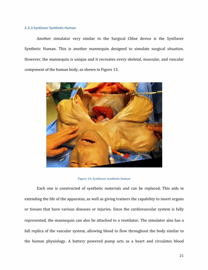
2.3.3 SynDaver Synthetic Human
Another simulator very similar to the Surgical Chloe device is the SynDaver
Synthetic Human. This is another mannequin designed to simulate surgical situation.
However, the mannequin is unique and it recreates every skeletal, muscular, and vascular
component of the human body, as shown in Figure 13.
Figure 13: SynDaver synthetic human
Each one is constructed of synthetic materials and can be replaced. This aids in
extending the life of the apparatus, as well as giving trainers the capability to insert organs
or tissues that have various diseases or injuries. Since the cardiovascular system is fully
represented, the mannequin can also be attached to a ventilator. The simulator also has a
full replica of the vascular system, allowing blood to flow throughout the body similar to
the human physiology. A battery powered pump acts as a heart and circulates blood

22
throughout the mannequin. This however, is the only vital sign that this simulator is
capable of producing. The accurate replication of human anatomy left little room for
electromechanical systems. Nevertheless, this type of simulation has its own place in
medical simulation training and is considered to be one of the more advanced instruments.
2.3.4 Strategic Operations Cut-Suit
The final simulator being examined is the Strategic Operations family of products.
These differ from the other simulators discussed in that they are not full body simulators.
Instead, they are human-worn pieces that simulate specific injuries. The Cut Suit is a
system worn by a human on the torso shown in Figure 14.
Figure 14: Cut suit
It consists of a realistic skin material with replaceable and interchangeable organs
underneath the skin. The suit also has a system capable of pumping blood through wounds.

23
While this system is not as fully controllable as some others, it allows the trainees to
interact with the patient in a much more realistic manner. This capability makes this very
appealing to users who want to simulate the panic and disorientation associated with high
trauma situations.
2.3.5 STRATUS Medical Simulation Technologies
2.3.5.1 Da Vinci System
Figure 15: Da Vinci Surgical System
The Da Vinci Surgical System is a dual-component system consisting of a control
console where the surgeon is stationed and a conglomeration of robotic arms that performs
the actual surgery (Figures 15 & 16). Controlled using EndoWrist® technology, the
surgeon’s hand movements are scaled down to very small, precise maneuvers by the
robotic instruments, resulting in extremely accurate and minimally invasive surgical
operations.

24
Figure 16: Da Vinci Surgical System at STRATUS
The core components of the Da Vinci are:
- 3D HD Vision- “Revolutionary 3D, high definition vision with up to 10x magnification,
bright, crisp, high-resolution image and an immersive view of the surgical field.
Improved visualization allows surgeons to handle and dissect delicate tissue with
added precision – even in confined spaces like the chest, abdomen or pelvis. This
precision allows the surgeon to minimize trauma to the surrounding anatomy, such as
the neurovascular bundle near the prostate during prostate cancer surgery” [28].

25
Figure 17: 3D HD Vision
- EndoWrist Instrumentation and Intuitive Motion—“As surgeons operate in confined
spaces of the body, Da Vinci instruments provide a range-of-motion that enhances
dexterity. Added dexterity enables surgeons to more accurately and easily perform
complex surgical maneuvers through small "ports”—eliminating the need for large,
traumatic incisions (as seen in Figure 18). EndoWrist instruments with 7 degrees of
freedom and a range of motion far greater than the human hand as well as reduction of
surgeon hand tremors” [28].
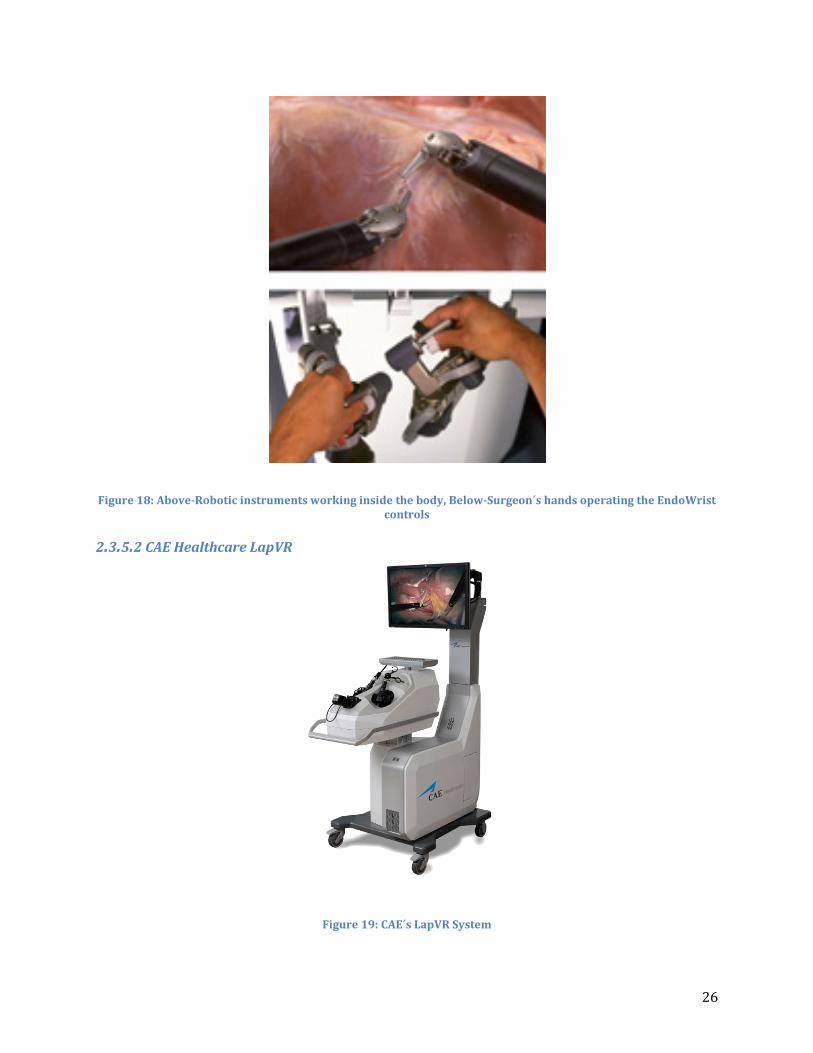
26
Figure 18: Above-Robotic instruments working inside the body, Below-Surgeon´s hands operating the EndoWrist controls
2.3.5.2 CAE Healthcare LapVR
Figure 19: CAE´s LapVR System

27
CAE Healthcare has introduced the LapVR, a simulator designed to provide students
and doctors with an accurate representation of various procedures and practices that they
will find in the minimally invasive surgical world, shown in Figure 19. Utilizing controls
taken from actual Laparoscopy machines and integrating software that operates like a
video game, allowing for depth and space to be recognized, results in users gaining critical
surgical skills in a risk-free environment.
“With the LapVR, learners are immersed in the most realistic skills training
environment available. LapVR gives learners the opportunity to develop proficiency in
techniques such as suturing, knot tying and loop litigation as well as some frequently
performed laparoscopic surgeries like gall bladder removal and tubal occlusion for risk-
free learning before they touch their first patient. The superior force feedback provides
accurate tactile, visual and audio responses to mimic the feel of real procedures” [29].
Figure 20: Performing an appendectomy using LapVR

28
A customizable curriculum allows instructors to follow the included programs as
well as uploaded alternative programs for a more specialized teaching environment
(Figure 20). LapVR can train anyone from new medical students to seasoned surgeons and
doctors by offering a huge range of programs, “from essential skills to advanced
procedures” [29].
The procedures offered include:
- Camera navigation
- Peg transfer
- Cutting
- Clipping
- Needle Driving
- Adhesiolysis
- Running the bowel
- Suturing and knot tying
- Loop ligation
- Laparoscopic cholecystectomy
- Laparoscopic appendectomy
- Bilateral tubal occlusion
- Ectopic pregnancy
- Salpingo oophorectomy
29
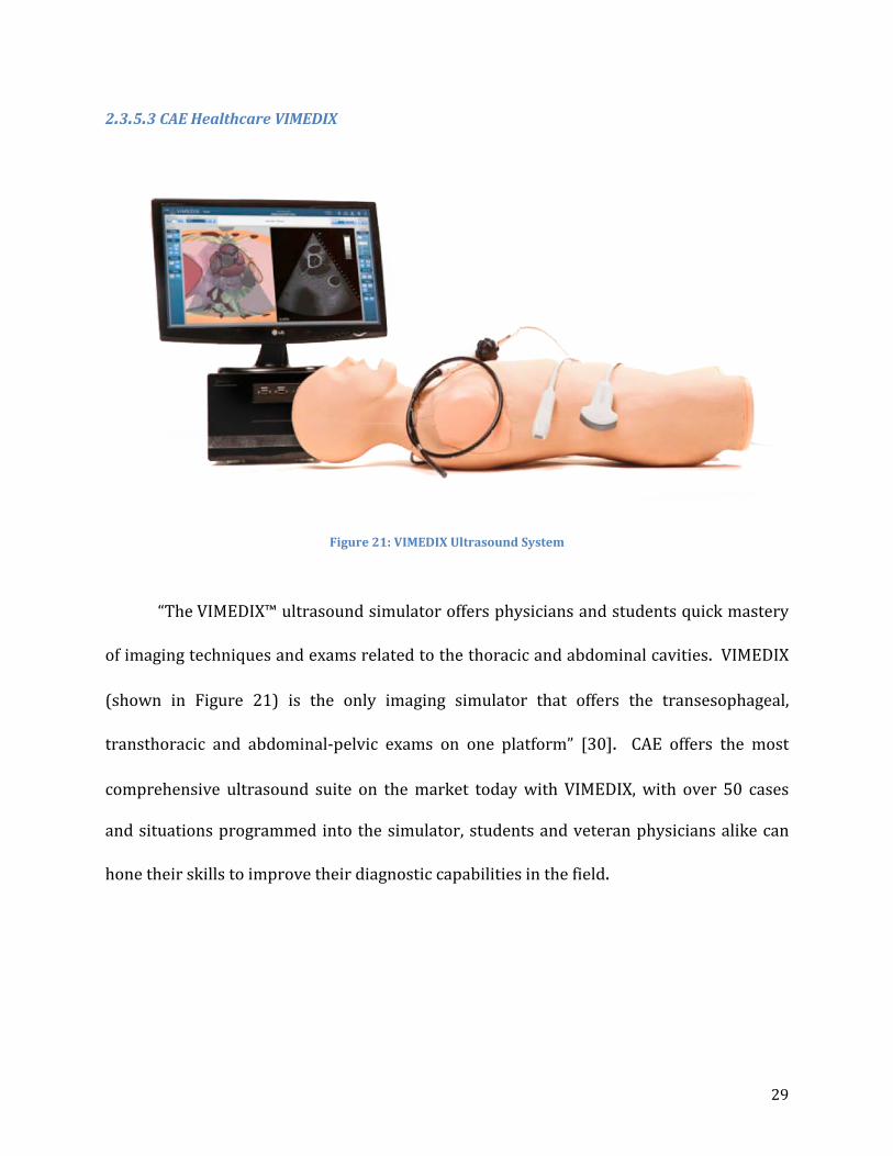
2.3.5.3 CAE Healthcare VIMEDIX
Figure 21: VIMEDIX Ultrasound System
“The VIMEDIX™ ultrasound simulator offers physicians and students quick mastery
of imaging techniques and exams related to the thoracic and abdominal cavities. VIMEDIX
(shown in Figure 21) is the only imaging simulator that offers the transesophageal,
transthoracic and abdominal-pelvic exams on one platform” [30]. CAE offers the most
comprehensive ultrasound suite on the market today with VIMEDIX, with over 50 cases
and situations programmed into the simulator, students and veteran physicians alike can
hone their skills to improve their diagnostic capabilities in the field.

30
2.3.5.4 Medsimulation SIMANTHA
Figure 22: SIMANTHA Endovascular Simulator
“Medical Simulation Corporation’s (MSC) endovascular simulation system (Figure
22), SIMANTHA, features sophisticated, reliable technology and a cognitive approach to
patient care that delivers comprehensive training experiences to increase the Competence
and Confidence® of healthcare providers. SIMANTHA has something to offer every member
of the interventional lab team, from nurses and technologists to experienced attending
physicians” [31].
Like other simulation technologies, SIMANTHA offers both students and
professionals a chance to train in a risk-free environment that is also extremely realistic.

31
SIMANTHA offers both individual and team training exercises and offers a training module
covering the entire care process from start to finish.
2.3.5.5 Immersion Medical AccuTouch Endoscopy Simulator
Figure 23: AccuTouch Endoscopy Simulator
“This system includes three types of endoscopic procedures: bronchoscopy, upper and
lower gastrointestinal endoscopy. It is a realistic, computer-based system for teaching and
assessing motor skills and cognitive knowledge, enabling residents to practice in a safe
environment. The case-based modules provide increasingly challenging patients to test
progress (Figure 23). The endoscopes look, feel and handle exactly like the real ones and

32
the simulator provides realistic force feedback, allowing the user to experience the feel of
the real procedure. The digital patients respond in a physiologically accurate manner
adding to the level of realism” [32].
2.3.5.6 Laerdal LMA Baby
Figure 24: (Left) Infant Laryngeal Mask Airway module, (Right) Dr. Pozner Demonstrating its Function
A physiologically accurate infant head and neck, developed to train all manner of
healthcare professionals on the proper way to perform LMA procedures and do quick and
accurate respiratory diagnostics on an infant/very young child. Developed to work with a
variety of LMA equipment, the head is made of silicone rubber overlaid on a hard plastic
“skeleton” for support. Silicone is used because it’s cheap, durable and has a texture
roughly similar to that of skin, it deforms similarly as well. Plastic bags (seen at the bottom
of the component in Figure 24) act as lungs, allowing realistic volumetric flow.

33
2.3.5.7 Laerdal SimBaby
Figure 25: (Left) SimBaby with components, (Right) SimBaby during Simulation
Similar to SimMan, SimBaby (Figure 25) has many different features making it
extremely valuable to a simulation center. Its functions include accurate conditions for
breathing, circulation, defibrillation, vascular system and anatomical traits. The airway can
be changed to reflect physiological changes, breathing patterns and blood pressure can
change sporadically, simulating sudden changes in the infant’s condition. IVs and other
needle-driving activities can be simulated using the IV arm and IO legs of the mannequin.
Also similar to SimMan, the software communicates directly with the mannequin and logs
all activity and conditions simulated during a specific procedure.
“The 17” touchscreen patient monitor provides 12 lead ECGs, SpO2, Hemodynamic
pressures, Cardiac Output and several other parameters. Set waveform parameters, alarm
functions and screen layouts. X-rays, lab results and videos can also be displayed on the
patient monitor”[33].

34
2.4 Artificial/Synthetic Skin Stanford University researchers have used carbon nanotubes and silicone to build
sensors that can stretch and deform, always returning back to its original shape, depicted
in Figure 26. It is composed of two layers of silicone, coated by single-walled carbon
nanotubes, and is separated by another silicone layer. Silicone can store electrical charge,
and pressure on the layers alters how much charge it can store. The material can sense
whether it’s being pressed or pinched. Essentially a skin strain gauge that measure changes
in electric current [34].
Figure 26: Stanford´s artificial silicone skin
The obvious use for this material is in prosthetic limbs, where one of the big
problems is giving the limb a sense of “feeling” to go along with motion. While there are
artificial limbs being developed that can be controlled by thought, it continues to be a
challenge to generate feedback that varies with pressure.

35
2.4.1 Properties of Human Skin
Skin is about 1.7 m2 in area and approximately 4 kg in weight, or 5.5% body mass.
The human skin is multifunctional and has extremely complex structure. It is multilayered
with complex and often indistinct interlayer boundaries, and its properties are different in
different directions. Its structure and function vary with the location of the body [35]. The
properties of skin also vary with the rate of application of stress and the length of time the
stress is maintained. It’s very sensitive to ambient conditions, age, and recent handling. The
skin has important protective functions against trauma such as friction, impact, pressure,
cutting and shear. It must be an active barrier between physiologic conditions within the
body and the varying, unfriendly ambient environment, while also helping to regulate the
internal environment (e.g. dissipating or conserving heat). Internal body structures must
have a controlled freedom of movement within, but also have some support from, the skin,
which must act as the nonslip intermediate surface when we grip, lift, or press. Skin renews
itself every 2-3 weeks [36].
The skin, like all biological material, is viscoelastic. Therefore, it experiences stress
relaxation and creep. When stretched, the collagen network inside the skin instantly adapt
to the condition to minimize the strain. Thus, the magnitude of the load to maintain the
given extension is gradually reduces to the minimum value. Conversely, the skin will
continue to stretch to a certain point when a load is applied. The collagen meshwork
structure within the skin is accountable for this behavior. The strength and elastic
properties of the skin also depend largely on the collagen content shown in Figure 27. As

36
mentioned earlier, properties of the skin vary with age. Younger skin is less protective
against large strains than older skin. Young skin is more viscous, or plastic than older skin.
Older skin has a proportionally greater elastic region in its stress-strain behavior than
younger skin.
Figure 27: Human skin stress-strain curve
The results of a carefully conducted in vitro testing of normal skin samples of
dimensions 4 mm long x 2 mm wide x the skin thickness approximately 1-2 mm are
summarized as follows. The tensile strength of human skin ranges from 5 to 30 MPa, with
the mean showing a maximum of about 21 MPa at age 8, and declining to about 17 MPa at
age 95. The ultimate modulus of elasticity ranges from 15 to 150 MPa, with the mean
showing a maximum of about 70 MPa at age 11, and slightly decline to about 60 MPa at age

37
95. The ultimate strain ranges from about 35 to 115%. The mean value linearly declines
from 75% at birth to 60% at age 95 [36].
2.4.2 Environmental Effects on Human Skin
Acceleration: due to the skin’s elastic nature, under extreme acceleration or if
exposed to a high-drag situation, such as riding a motorcycle without a helmet, the looser
skin around the face can deform and fold back into wrinkles due to air friction and drag.
However, by and large, acceleration has no last effects on the surface of the skin. Under
heavy negative loads (3g and up from feet to head) effects on the body can become
significant and can lead to obvious signs under the surface of the skin. At 5 g’s, small or
weak veins and capillaries in the face can rupture causing red splotches or bruising on the
face and red spots in the eyes. Intense positive acceleration (head to feet) of similar
magnitudes can result in the rupturing of small veins and capillaries in the body’s
extremities. Thus, the most commonly observable and lasting effects occur not on the
surface of the skin, but rather just underneath it [37].
Pressure: Depending on the magnitude of the pressure applied to the skin, such as
pressure resulting from acceleration as mentioned above, or pressure from a body pressing
upon the skin (such as a rock or perhaps being underwater), human skin can become
elastically deformed and changes in blood pressure can be measured. “Pressures ranging
between 5 and 150 mmHg were applied through a 3-cm-diameter disc placed over the site
of flow determination. The pressure was maintained constant by a servo-controlled loading
mechanism. Flow decreased with pressures from 5 to 10 and 30 to 150 mmHg, but

38
remained constant with pressures from 10 to 30 mmHg. Reactive hyperemia occurred
following removal of pressures of 90 mmHg or greater, but did not occur following removal
of lower pressures.” Thus, the application and removal of certain magnitudes of pressure
can have significant effect on the person’s blood pressure, which can in turn affect the rest
of their body and organs [38].
Energy: Electro-magnetic radiation, because humans are so rarely, if ever, subjected
to extreme electro-magnetic radiation, it is unclear the effects that it would have on human
skin. Normal amounts of radiation that a human is subjected to on a daily basis (cell
phones, Wi-Fi, microwaves, etc.) causes negligible changes in skin tone, temperature or
constitution. Solar radiation however, has very significant effects on human skin,
particularly if that skin is low in melanin (pigment), such as the paler ethnicities that
typically inhabit the upper and lower sections of the Northern and Southern hemispheres
where solar radiation is less intense.
Depending on your skin tone, humans are more or less susceptible to first or second
degree burns from prolonged exposure to the ultraviolet (UV) rays in sunlight. Sunburns
can result in red, irritated skin. Typically contact with irritated skin is painful and in more
intense cases, the outer layer of skin is killed by the radiation and peels off over the course
of several days or can form blisters. Repeated sunburns or excessive UV exposure has been
linked to multiple types of skin cancers. Coincidentally, moderate exposure to sunlight
allows the body to produce vitamin D, which is intrinsic to healthy skin. Obviously the

39
application of an extremely hot medium, such as fire or anything that is burning, to human
skin will result in intense pain, redness and burns between the second and third degree
[39].
2.4.3 Skin Reaction to Chemicals
Chemical agents are the main source of skin diseases and disorders. From this, they
are split into two different groups: primary irritants and sensitizers. Primary irritants
directly impact the skin through chemical reactions, and sensitizers may not cause an
immediate response from the skin, but prolonged and repeated exposure to the chemical
can cause allergic reactions. A person may be exposed to these hazardous chemicals
through, “direct contact with contaminated surfaces, deposition of aerosols, immersion, or
splashes” [40].
Dermal Absorption is the transport of a chemical from the outer surface of the skin
both into the skin and into the body. Studies show that absorption of chemicals through the
skin can occur without being noticed by the worker, and in some cases, may represent the
most significant exposure pathway. Many commonly used chemicals in the workplace
could potentially result in systemic toxicity if they penetrate through the skin (i.e.
pesticides, organic solvents, etc.). These chemicals enter the blood stream and cause health
problems away from the site of entry.
40
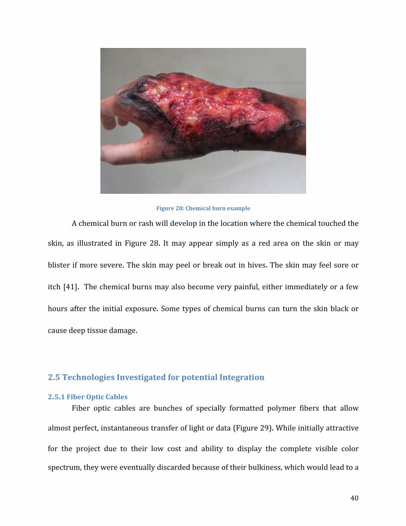
Figure 28: Chemical burn example
A chemical burn or rash will develop in the location where the chemical touched the
skin, as illustrated in Figure 28. It may appear simply as a red area on the skin or may
blister if more severe. The skin may peel or break out in hives. The skin may feel sore or
itch [41]. The chemical burns may also become very painful, either immediately or a few
hours after the initial exposure. Some types of chemical burns can turn the skin black or
cause deep tissue damage.
2.5 Technologies Investigated for potential Integration
2.5.1 Fiber Optic Cables Fiber optic cables are bunches of specially formatted polymer fibers that allow
almost perfect, instantaneous transfer of light or data (Figure 29). While initially attractive
for the project due to their low cost and ability to display the complete visible color
spectrum, they were eventually discarded because of their bulkiness, which would lead to a

41
difficult installation, and their inability to produce ‘life like’ colors. This technology should
not be entirely ignored by the medical simulation industry however; they could certainly
be applied to a project with more space than ours.
Figure 29: Examples of fiber optic applications
2.5.2 Organic Light Emitting Diodes (OLEDs) Given the specifications and objectives of the project, Organic Light Emitting Diode
technology is the most attractive option (Figure 30). OLEDs are extremely thin, on the
order of a millimeter or less and are flexible. A screen made of this material has the highest
resolution, highest contrast ratios, and highest viewing angle of any screen currently on the
market in addition to its other properties. Furthermore, they require only a small amount
of the power that similarly sized displays would consume and produce relatively small
amounts of heat.

42
Figure 30: Breakdown of a OLEDs structure
Unfortunately, the technology is still being developed and produced and is just
starting to be mass-produced which means the initial cost of such a display is high.
However, the team is confident that once mass production of such displays have begun, and
our project is scaled up, the cost will decrease significantly.
2.5.3 Polymerized Crystalline Colloidal Array
This is an extremely new technology that has been patented by Dr. Sanford Asher et
al. at the University of Pittsburgh. Essentially, the polymers are suspended in a hydrogel
network that responds physically to electrical current by changing its bulk volume. When
the gel deforms, the polymers arrange themselves in a specific crystalline structure, which
causes the light shining through them to refract into various colors, similar to a prism.
Changing their orientation will cause the light to ‘red-shift’ or reverse its color (Figure 31).
43
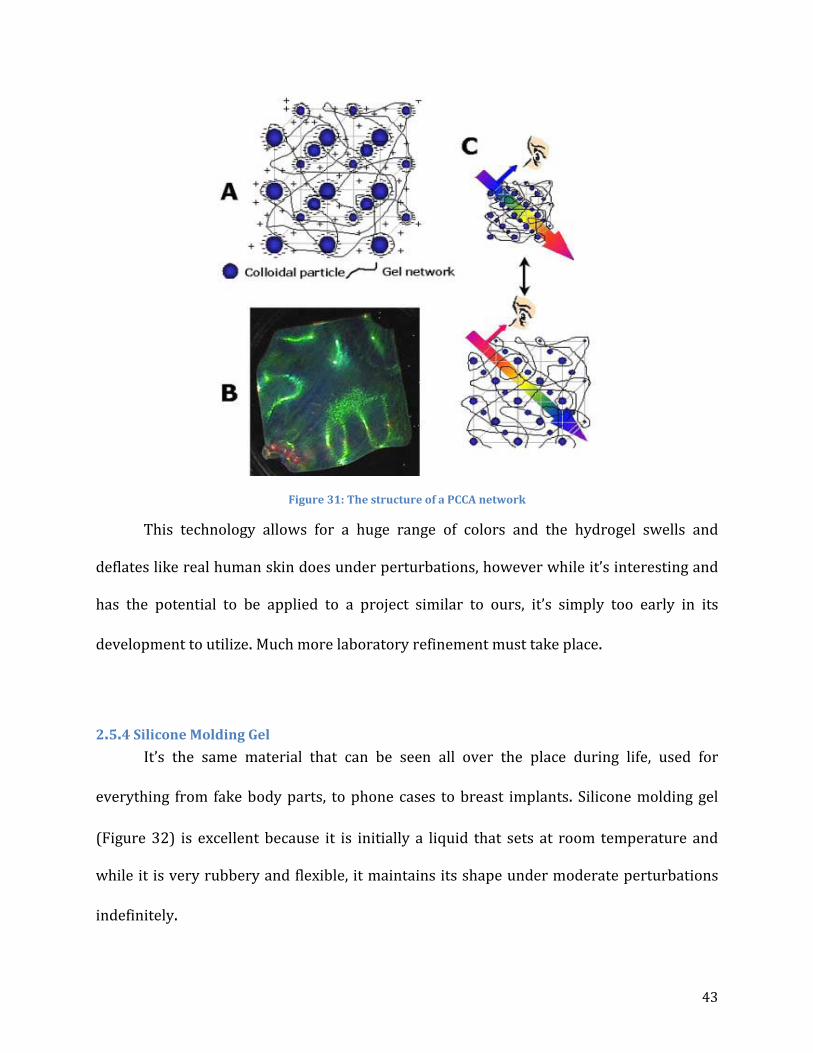
Figure 31: The structure of a PCCA network
This technology allows for a huge range of colors and the hydrogel swells and
deflates like real human skin does under perturbations, however while it’s interesting and
has the potential to be applied to a project similar to ours, it’s simply too early in its
development to utilize. Much more laboratory refinement must take place.
2.5.4 Silicone Molding Gel It’s the same material that can be seen all over the place during life, used for
everything from fake body parts, to phone cases to breast implants. Silicone molding gel
(Figure 32) is excellent because it is initially a liquid that sets at room temperature and
while it is very rubbery and flexible, it maintains its shape under moderate perturbations
indefinitely.

44
Figure 32: Silicone gel being poured to set
This material was an easy choice for the project because it has similar properties to
skin, feels similar to skin, is waterproof and will also provide a layer of protection for our
OLED displays. The standard gel is translucent, but not entirely clear. It has just enough
opaqueness to dim the display of the OLED to produce more realistic hues and tones of the
skin.

45
CHAPTER 3: VIRTUAL HUMAN SKIN
3.1 Motivation Within the medical field, medical practitioners must first pass rigorous practical and
analytical exams before being able to practice medicine professionally. However, not every
procedure can be tested for with qualification exams. This is where medical simulation
plays an important role in developing new skills as well as honing existing ones. For
medical simulation, mannequins are used to simulate real life situations without the
potential drawbacks of these real life situations.
From a medical professional’s point of view, the first thing he or she looks at when
diagnosing a patient is the skin. Just from looking at the skin, a medical professional can
tell whether there is something wrong with the patient as well as start to categorize the
patient’s symptoms into a preliminary diagnosis. With existing medical simulation
mannequins, this is not possible. On current mannequin models, the skin is comprised of
just flesh-tone silicone, which cannot display signs of illness, let alone change color. This
MQP team wanted to bring a new skin to the medical simulation field that would enhance
the medical simulation experience. This would ultimately improve intrinsic centric
composite care (IC3) which would therefore better prepare medical practitioners to
perform at their peak performance.
3.2 Objectives and Goals For this project, the team wanted to be able to understand the color changes of
human skin with respect to perturbations, which includes but is not limited to: rashes,
46
bruises, flushness, and paleness. In addition, the team wanted to increase the practicality
of medical training by improving the way medical practitioners utilize medical simulation.
To do this, the MQP group needed to identify which technologies could and should be
integrated into this project as well as evaluate the design goals and specifications, which
would be implemented into a prototype proof of concept that was designed and produced.
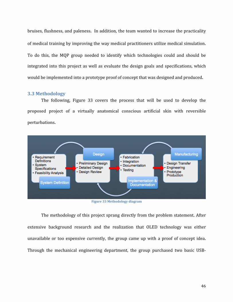
3.3 Methodology The following, Figure 33 covers the process that will be used to develop the
proposed project of a virtually anatomical conscious artificial skin with reversible
perturbations.
Figure 33 Methodology diagram
The methodology of this project sprang directly from the problem statement. After
extensive background research and the realization that OLED technology was either
unavailable or too expensive currently, the group came up with a proof of concept idea.
Through the mechanical engineering department, the group purchased two basic USB-

47
powered LCD screens and two pints of silicone molding rubber and some flesh-tone
pigment.
The screen casings were removed to save space and then measured to get
dimensions. Our team then designed a casing for the screens using SolidWorks®
computer-aided design software. Five pieces were modeled, designed to fit together like a
puzzle to ensure a stable final product. The five parts were then combined into an assembly
in SolidWorks and reviewed by our advisor, Professor Fofana and sponsor, Dr. Charles
Pozner for approval.
Once approved, the team ordered four 2 ft. x 2 ft. pieces of .25 inch thick extruded
acrylic sheeting. Each part model was then transferred to a AutoCAD drawing template and
uploaded into the computer in the Washburn machine shop that controls the laser-cutter.
Each piece was then individually cut, assembled and secured using superglue. The screens
were placed into the housing to make sure they fit and then plugged into a computer via
their USB cables so the team could test them.
After proving the screens worked as advertised, the team created a mold for the
silicone out of a pine board and steel sheeting. The silicone was mixed and then poured
into the molds in various thicknesses ranging from 2mm to 8mm and left to set for four
hours. Once the silicone had set, each piece was placed over the screens to observe the
effect. The screens worked best with the thinner pieces, 2 and 3mm respectively. It should

48
be noted that OLED screens can be made brighter with less power consumption than LCD
screens and as such could be coupled with thicker silicone.
It was found that the original prototype housing didn’t quite fit the screens and
silicone sheets properly. Full-sized silicone sheets were set by pouring the silicone directly
into the housing to ensure a proper fit. It was found that the original prototype housing
didn’t quite fit the screens and silicone sheets properly and that the silicone set in the
housing took on a very smooth, glossy finish from the smooth bottom of the housing. This
was undesirable because in high-light situations, such as an operating room, there was
significant glare on the surface of the silicone which decreased the angle at which the
screens could be viewed.
Another undesirable effect was that the flesh-tone pigment, even in small amounts,
caused the screens to appear too dark and resulted in altered colors. It was decided that
the clear-colored silicone rubber sheets were a better choice for the skin. New
measurements were taken and the original dimensions were adjusted. The team once again
laser-cut the acrylic pieces and assembled them using superglue.
This second version of the housing performed much better, the bottom of the
housing was sanded to create a matte finish on the set silicone which increased viewing
angle and decreased glare significantly. The screens were inserted into the new housing,
fitted tightly to prevent shifting during operation and the silicone sheet was placed atop
them, sitting flush with the edges of the housing, creating a perfect rectangular prism.

49
The team then set about finding various pictures and creating video loops of general
skin conditions such as cyanosis and bruising to display on the screens, to great effect.
From there the team presented their second prototype to Dr. Pozner and Professor Fofana
for approval, the skin conditions presented on the screens were very popular as they
heavily reinforced our proof of concept. And finally, the prototype and the team’s
corresponding poster were presented at WPIs Project Presentation Day on April 18th.

50
3.4 Task Specification 1. Skin color must be reversible, subject to perturbations
2. Texture of the artificial skin must be similar/equal real skin
3. The artificial skin must encompass physiological characteristics
4. Durable with a life cycle of five to ten years
5. The thickness of the skin must be 5 ±1mm
6. Viewing angle of the artificial skin should be as close to 180° as possible.
7. Must be supported by the mannequin’s 12V power source
8. Should integrate with the current technology of the medical simulation mannequin
3.5 Preliminary Design
3.5.1 Fatigue Analysis Based on data gathered from various sources and a small amount of experimental
data gathered, the team developed a preliminary fatigue analysis of the OLED system. From
a study done on the material properties and tensile resilience of OLED screens and their
substrates, it is found that the yield strength of the material is approximately 77 MPa [42].
Based the design, the analysis is only necessary on screens, which will be on the
chest because they will be directly affected by trainees performing CPR. The analysis was
done based on the compressive force measured experimentally from an equal group of men
and women performing CPR in Figure 34. The average force was 125 lbs. or about 20,680
Pa.
51
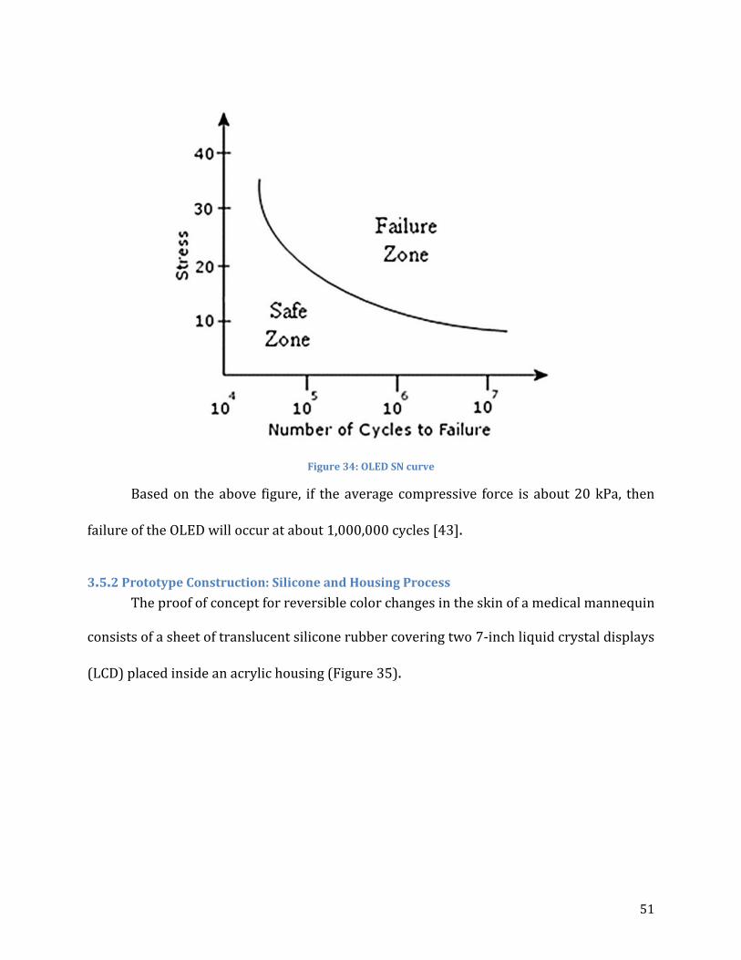
Figure 34: OLED SN curve
Based on the above figure, if the average compressive force is about 20 kPa, then
failure of the OLED will occur at about 1,000,000 cycles [43].
3.5.2 Prototype Construction: Silicone and Housing Process The proof of concept for reversible color changes in the skin of a medical mannequin
consists of a sheet of translucent silicone rubber covering two 7-inch liquid crystal displays
(LCD) placed inside an acrylic housing (Figure 35).

52
Figure 35: Prototype
The platinum cure liquid silicone compound with the trade name of Dragon Skin ®
20 (Appendix B) was purchased from Reynolds Advance Materials. The 2-part liquid
compounds are mixed 1A:1B by weight or volume to produce solid silicone rubber after the
mix is cured for 4 hours. The thickness of the silicone rubber sheet will have an effect on its
translucency; thus, a contraption was constructed to find the optimal thickness. The
wooden device was designed to have five sections separated by metal sheets, as shown in
Figure 36. Each rectangular section is roughly 4in long and 2.5in wide. Two batches were
made for the thickness test—one with flesh-tone pigment added and one without (Figure
37). The test sheets have the thicknesses ranging from 2mm to 8mm.

53
Figure 36: Silicone thickness testing device.
Figure 37: Silicone rubber thickness test sheets with and without pigment

54
Despite the realistic appearance of the flesh-tone silicone sheets, the silicone sheets
without the pigment added showed much better visibility of the display beneath.
Furthermore, the thinnest silicone sheet was concluded to be the best option due to the
least amount of trapped air pockets and impurities, which interfere with the display
visibility.
A housing is necessary to neatly store all of the display components. Acrylic sheets
were decided to be the best material for this application, provided that a laser cutter is
accessible in the Washburn Shops. A simple rectangular box was designed, as shown in
Figure 38, so that the displays could place in the top-to-bottom arrangement, detailed
drawings of the housing can be found in Appendix C. Two supports were integrated into
the housing to level and elevate the displays from the circuit boards and cables.
Figure 38: Housing

55
After the housing was constructed, the silicone rubber sheet was molded directly
onto it to provide good fitting. However, the resulting silicone sheet provided poor
visibility to the display when viewed at an angle in a bright environment because of the
reflective finish surface due to the smooth surface of the acrylic. Furthermore, the
dimensions of the housing appeared to have room for improvements. Therefore, another
housing was designed and constructed with better dimensions. And prior to the assembly
of the housing, the surface of the base component was roughened with sand paper to
eliminate reflections off of the silicone sheet after it was molded onto it.

56
CHAPTER 4: CONCLUDING REMARKS This project aims to improve the quality of training for medical practitioners by
increasing the fidelity of medical simulators. In order to do this it was decided to develop a
system that effectively displays physiological changes in the skin associated with various
changes that occur in the body. These physiological changes included cyanosis, redness,
paleness, rashes, and bruising, among others. First, background research was done in order
to determine the range of colors needed to be represented, in addition to other
specifications the design needed to meet.
Due to the need for a large color range and flexibility, a design was developed using
flexible Organic Light Emitting Diode (OLED) displays. This design uses a flexible OLED
display coated in a clear silicone rubber, which in turn is connected to the computer
hardware inside of SimMan. This combination of a silicone rubber layer on top of a flexible
OLED display would be used in place of the current skin.
This design proved effective in theory, however the manufacturers of flexible OLED
displays hit production issues and the screens will not be available until December 2013.
Since this fell outside the time range of this project, proving other aspects of the design
became paramount. A proof of concept was developed using two rigid LCD screens which
showed that similar display technology would effectively show physiological skin changes.
In addition, a theoretical fatigue analysis was done on the OLED substrate that
showed the displays would withstand approximately one million cycles of CPR. These

57
results, combined with input from other stakeholders, illustrates that this is an effective
design and more work should be done to continue developing the technology for use in
medical simulation. In order to do this, flexible OLED screens will need to be procured, a
mounting system must be designed for both the silicone onto the OLED substrate as well as
the skin combination onto the mannequin, the computer hardware on SimMan must be
upgraded in order to handle the displays, and software must be developed in order to
modify what is being displayed on the mannequin. Once this is completed the technology
will dramatically improve the fidelity of medical simulation.

58
REFERENCES 1. J.Bank, J. Carson, B. Nelson, D, Nicol(2001). Discrete-Event System Simulation.
Pentice Hall. P. 3.
2. "Simulation." Wikipedia. Wikimedia Foundation, 2013. Web. <http://en.wikipedia.org/wiki/Simulation>.
3. "Traffic Simulation." Wikipedia. Wikimedia Foundation, 9 Apr. 2013. Web. <http://en.wikipedia.org/wiki/Traffic_simulation>.
4. “Pursula.” University of Western Ontario. 2013. <http://publish.uwo.ca/imalczew/gida_5/Pursula/Pursula.html>.
5. Sokolowski, J.A., & Banks, C.M. (2009). Principles of modeling and simulation: A multidisciplinary approach. Hoboken, NJ. John Wiley
6. Leemis, L.M., & Park, S.K. (2006). Discret-event simulation: A first course. Upper Saddle River, NJ. Pearson Hall.
7. "Monte Carlo method." Wikipedia. 23 Mar. 2013. Wikimedia Foundation. <http://en.wikipedia.org/wiki/Monte_Carlo_method>.
8. "Continuous simulation." Wikipedia. 19 Jan. 2013. Wikimedia Foundation. 22 Apr. 2013 <http://en.wikipedia.org/wiki/Continuous_simulation>.
9. Fox, Ken. "Introduction to Micro-simulation." Micro-simulation. <http://www.microsimulation.drfox.org.uk/intro.html>.
10. Assad, Arjang A.,(1979). Models for rail transportation. Transportation Research Part A: General Volume 14. Issue 3. Pages 205-220
11. "Numerical weather prediction." Wikipedia. 17 Apr. 2013. Wikimedia Foundation. <http://en.wikipedia.org/wiki/Numerical_weather_prediction>.
12. Baklanov, Alexander; Rasmussen, Alix; Fay, Barbara; Berge, Erik; Finardi, Sandro (September 2002). "Potential and Shortcomings of Numerical Weather Prediction Models in Providing Meteorological Data for Urban Air Pollution Forecasting". Water, Air and Soil Pollution: Focus 2 (5): 43–60.
13. Chalikov, D. V. (August 1978).

59
14. "Numerical weather prediction." Wikipedia. 17 Apr. 2013. Wikimedia Foundation.
<http://en.wikipedia.org/wiki/Numerical_weather_prediction>.
15. Bender, Leslie C. (January 1996).
16. Strickland, Jonathan. "How Virtual Reality Military Applications Work." HowStuffWorks. <http://science.howstuffworks.com/virtual-military.htm>.
17. "Virtual Simulation Systems." 2013. <http://www.virtualsimulationsystems.com/>.
18. "NASA Ames Research Center History." NASA - National Aeronautics and Space Administration. 2013. NASA. <http://www.nasa.gov/centers/ames/about/history.html>.
19. "Virtual Airspace Simulation Technologies Real-Time." NASA Ames Aviation Systems Division. 2013. NASA. <http://www.aviationsystemsdivision.arc.nasa.gov/facilities/vast/index.shtml>.
20. "Vertical Motion Simulator." NASA Ames Aviation Systems Division. 2013. NASA. <http://www.aviationsystemsdivision.arc.nasa.gov/facilities/vms/index.shtml>.
21. "FutureFlight Central." NASA Ames Aviation Systems Division. 2013. NASA. <http://www.aviationsystemsdivision.arc.nasa.gov/facilities/ffc/index.shtml>.
22. "CVSRF B747-400 Simulator." NASA Ames Aviation Systems Division. 2013. NASA.
<http://www.aviationsystemsdivision.arc.nasa.gov/facilities/cvsrf/index.shtml>.
23. "Prestan Manikins." CPR Savers & First Aid Supply. 2013. <http://www.cpr-savers.com/Industrials/Cpr prod/cpr manikins/prestan-medium-skin.html>.
24. "SimMan." Laerdal. 2013. <http://www.laerdal.com/us/essential>.
25. Murph, Darren. "Medical students treat dummies that bleed, speak, and die." Engadget. 7 Dec. 2006. Engadget. <http://www.engadget.com/2006/12/07/medical-students-treat-dummies-that-bleed-speak-and-die/>.
26. "SimMan." EMS, Medical, Rescue & Training Simulators. 2013. Firehouse Medical, Inc. <https://www.firehousemedical.com/store3/manufacture/laerdal-medical-corp/simman.html>.
60
27. "'Surgical Chloe': New Army medical training aid is no dummy." San Antonio
Express-News. 15 Aug. 2012. My San Antonio. <http://www.mysanantonio.com/news/military/article/Surgical-Chloe-New-Army-medical-training-aid-3787989.php>.
28. "Core Technology of the da Vinci® Surgical System." Intuitive Surgical. 2013. <http://www.intuitivesurgical.com/products/davinci_surgical_system/features_benefits/>.
29. "LapVR Surgical Simulator." CAE Healthcare. 2013. <https://caehealthcare.com/home/eng/product_services/product_details/lapvr>.
30. "VIMEDIX Ultrasound Simulator." CAE Healthcare. 2013. <https://caehealthcare.com/0/eng/product_services/product_details/vimedix>.
31. "Simantha." Medical Simulation Corporation. SimSuite. 2013. <http://www.medsimulation.com/Simantha.asp>.
32. "Endoscopy." University of Mississippi Medical Center. 2013. <http://surgery.umc.edu/facultystaff/learning/SSC/endoscopy.html>.
33. "SimBaby™." 2013. Laerdal. <http://www.laerdal.com/us/SimBaby>.
34. Emspack, Jesse. "Skinlike Material Stretches and Senses." DNews. 26 Oct. 2011. <http://news.discovery.com/tech/skinlike-material-stretches-senses-111026.html>.
35. Edwards, Christopher, and Ronald Marks. "Evaluation of Biomechanical Properties of Human Skin." 1995. Elsevier Science Inc. <http://courses.washington.edu/bioen327/Labs/Lit_BiomechPropsSkin.pdf>.
36. Edwards, Christopher, and Ronald Marks. "Evaluation of Biomechanical Properties
of Human Skin." 1995. Elsevier Science Inc. <http://courses.washington.edu/bioen327/Labs/Lit_BiomechPropsSkin.pdf>.
37. "Acceleration Stress (Physiology)." Encyclopedia Britannica Online. 2013. Encyclopedia Britannica. <http://www.britannica.com/EBchecked/topic/2846/acceleration-stress>.

61
38. Holloway, G. A., C. H. Daly, D. Kennedy, and J. Chimoskey. "Effects of external pressure loading on human skin blood flow measured by 133Xe clearance." Journal of Applied Physiology. 2013. American Physiological Society. <http://jap.physiology.org/content/40/4/597.abstract>.
39. Dephoff, Jacklyn. "The Effects of Solar Radiation." EHow. 06 Nov. 2009. Demand Media. <http://www.ehow.com/about_5616154_effects-solar-radiation.html>.
40. Coila, Bridget. "Chemical Burns & Rashes." LIVESTRONG.COM. 7 Sept. 2010. <http://www.livestrong.com/article/232498-chemical-burns-rashes/>.
41. "Skin Exposures & Effects." Centers for Disease Control and Prevention. 30 Apr. 2012. <http://www.cdc.gov/niosh/topics/skin/>.
42. Hong Lee Yow, Soo Jin Chua. Mechanical Properties of Organic Light-Emitting Thin Films
43. Yavuz, Metin. "Plantar shear: Casting light on ‘dark matter’." Lower Extremity Review Magazine. May 2010. <http://lowerextremityreview.com/article/plantar-shear-casting-light-on-dark-matter>.

62
APPENDICES
Appendix A: STRATUS Center Pictures
Figure 39: SimMan 3G™
Figure 40: Arm of SimMan 3G™

63
Figure 41: SimMan 3G™ Work Station
Figure 42: Infant incubation simulator
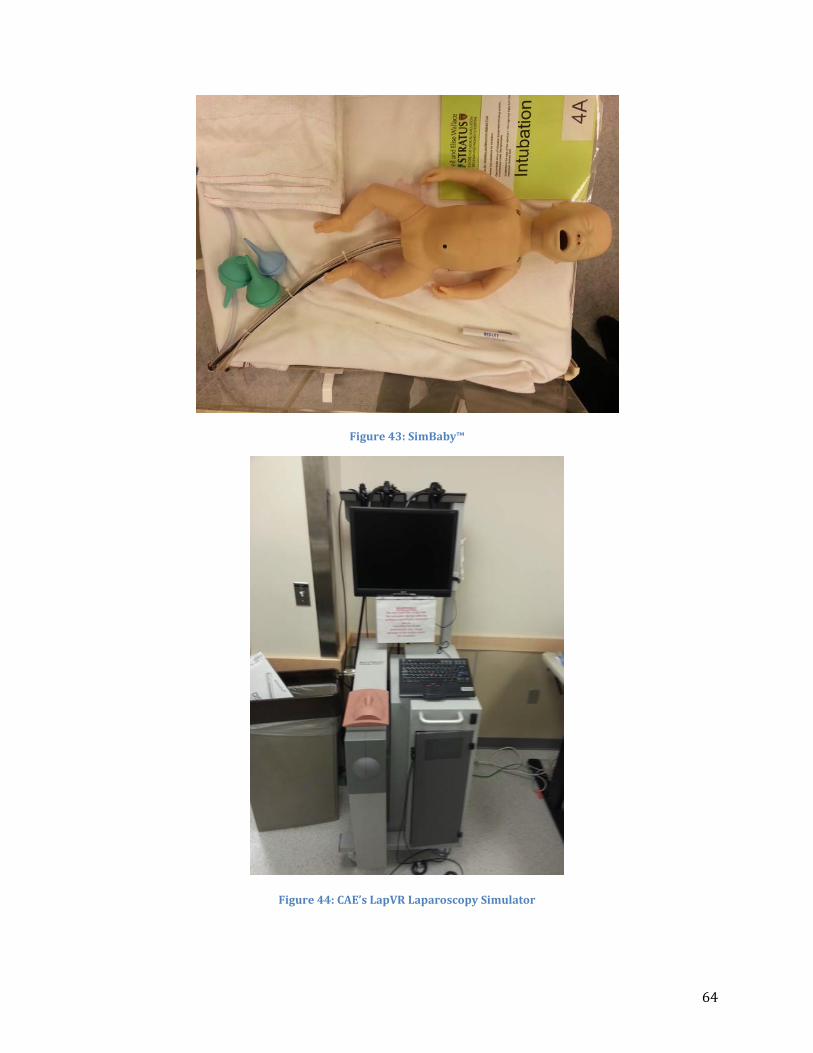
64
Figure 43: SimBaby™
Figure 44: CAE’s LapVR Laparoscopy Simulator

65
Figure 45: SimMan medical simulator

66
Appendix B: Silicone Rubber Compounds
Figure 46: Dragon Skin 20 Silicone Rubber Compounds
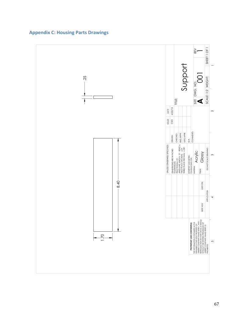
67
Appendix C: Housing Parts Drawings

68
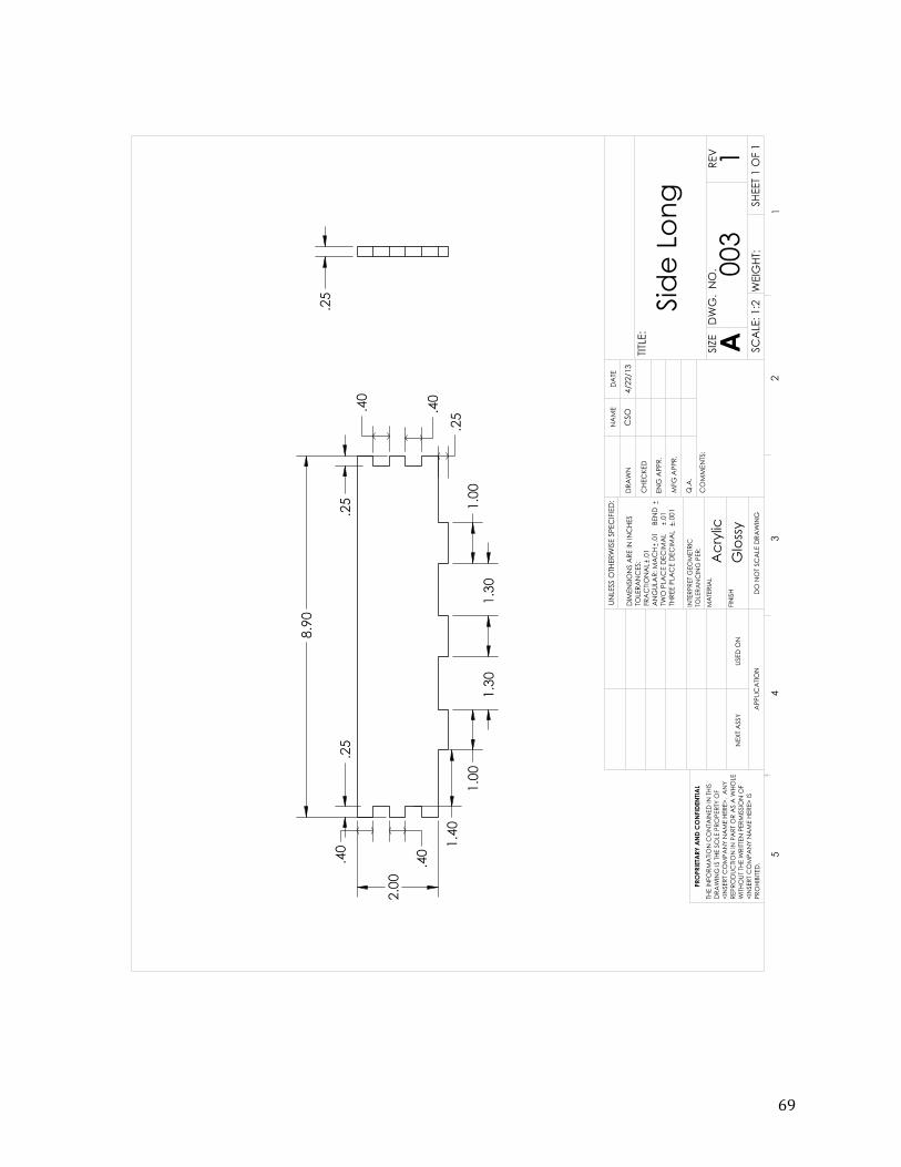
69
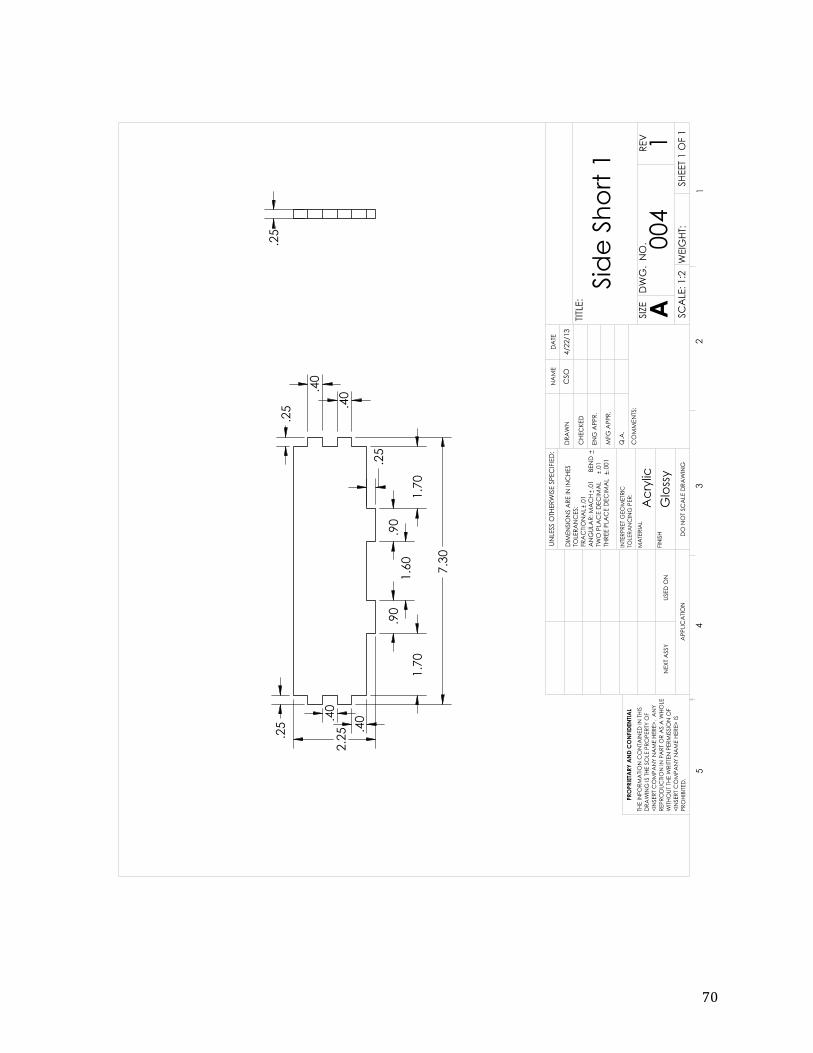
70
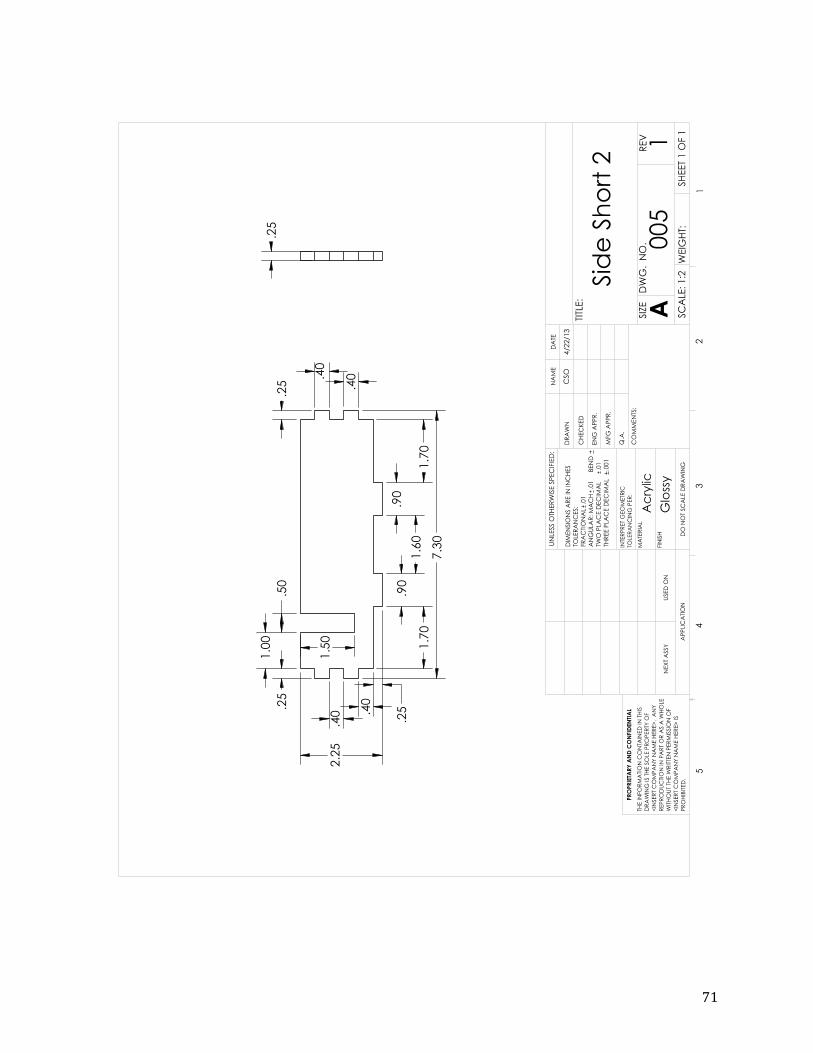
71