Artifacts in optical coherence...
7
Retinal and Choroidal Imaging Update Artifacts in optical coherence tomography Jay Chhablani, MS a,⇑ ; Tandava Krishnan, MS b ; Vaibhav Sethi, MS a ; Igor Kozak, MD, PhD c Abstract Optical coherence tomography (OCT) is now an integral part of management for numerous retinal diseases for diagnosis, treat- ment planning and follow up. OCT interpretation must involve the understanding of the associated artifacts. These artifacts can mislead physicians to wrong diagnosis or inappropriate management. This review article discusses the various types of artifacts in OCT scans obtained from various devices in various retinal diseases. This article would help to improve the understanding about the various artifacts and their clinical importance. Keywords: Optical coherence tomography, Time domain optical coherence tomography, Spectral domain optical coherence tomography, Cirrus, TOPCON, Spectralis, Artifacts 2014 Saudi Ophthalmological Society, King Saud University. Production and hosting by Elsevier B.V. All rights reserved. http://dx.doi.org/10.1016/j.sjopt.2014.02.010 Introduction Optical coherence tomography (OCT) is a non-invasive imaging modality useful for identification of lesions in the macula, optic disk and the anterior segment. 1 It provides a high resolution, in vivo optical biopsy of the tissue being scanned, using the principle of optical interferometry. 2,3 OCT can be in the form of Time Domain OCT (TD OCT) or Fourier domain OCT. In TD OCT a mechanically moving scan- ning reference arm sequentially measures the echo time delay. 1 Fourier domain OCT has a stationary reference arm which obtains an interference spectrum which then under- goes Fourier transformation allowing simultaneous measure- ments of all echo time delays thereby reducing the image acquisition time. Fourier domain OCT is again subdivided into Spectral Domain OCT (SD OCT) which uses a spectrom- eter and a line scan camera for image acquisition as opposed to a swept source OCT which has a rapidly tunable laser source for the same purpose. 4 Information gathered from OCT can be qualitative or quantitative in nature. Qualitative data can be in the form of identification of retinal pathologies like vitreo macular traction, macular holes, cystoid macular edema and choroidal neovascular membrane. 1 Quantitative data such as foveal thickness are used to make treatment decisions like in condi- tions such as age related macular degeneration, diabetic macular edema and retinal vein occlusions. 5–8 Likewise retreatment decisions are also based to some extent on the foveal thicknesses obtained by an OCT scan. Interpretation of these data and their implications in clini- cal situations must be tempered by the fact that images thus obtained are subject to artifacts. 3 These artifacts can mislead physicians to wrong diagnosis or inappropriate management. The first step for an examiner to address the issue of artifacts is to be aware of the presence of artifacts. 9 Knowledge about the possible artifacts in an OCT image will aid in better inter- pretation of the disease condition. Here we describe various types of artifacts and their clinical significance. Peer review under responsibility of Saudi Ophthalmological Society, King Saud University Production and hosting by Elsevier Access this article online: www.saudiophthaljournal.com www.sciencedirect.com Available online 6 March 2014 a Smt. Kanuri Santhamma Retina Vitreous Centre, L.V. Prasad Eye Institute, Kallam Anji Reddy Campus, L.V. Prasad Marg, Banjara Hills, Hyderabad 500 034, India b Vitreo Retinal Services, Vasan Eye Care Hospital, Hyderabad, India c Division of Vitreoretinal Diseases and Surgery, King Khaled Eye Specialist Hospital, P.O. Box 7191, Riyadh 11462, Saudi Arabia ⇑ Corresponding author. Tel.: +91 40 30612607. e-mail address: [email protected] (J. Chhablani). Saudi Journal of Ophthalmology (2014) 28, 81–87
-
Upload
duongthien -
Category
Documents
-
view
223 -
download
2
Transcript of Artifacts in optical coherence...

Saudi Journal of Ophthalmology (2014) 28, 81–87
Retinal and Choroidal Imaging Update
Artifacts in optical coherence tomography
Peer review under responsibilityof Saudi Ophthalmological Society,King Saud University Production and hosting by Elsevier
Access this article onlinwww.saudiophthaljournwww.sciencedirect.com
Available online 6 March 2014
a Smt. Kanuri Santhamma Retina Vitreous Centre, L.V. Prasad Eye Institute, Kallam Anji Reddy Campus, L.V. Prasad Marg, Banjara Hills, Hyd500 034, Indiab Vitreo Retinal Services, Vasan Eye Care Hospital, Hyderabad, Indiac Division of Vitreoretinal Diseases and Surgery, King Khaled Eye Specialist Hospital, P.O. Box 7191, Riyadh 11462, Saudi Arabia
⇑ Corresponding author. Tel.: +91 40 30612607.e-mail address: [email protected] (J. Chhablani).
Jay Chhablani, MS a,⇑; Tandava Krishnan, MS b; Vaibhav Sethi, MS a; Igor Kozak, MD, PhD c
Abstract
Optical coherence tomography (OCT) is now an integral part of management for numerous retinal diseases for diagnosis, treat-ment planning and follow up. OCT interpretation must involve the understanding of the associated artifacts. These artifacts canmislead physicians to wrong diagnosis or inappropriate management. This review article discusses the various types of artifacts inOCT scans obtained from various devices in various retinal diseases. This article would help to improve the understanding aboutthe various artifacts and their clinical importance.
Keywords: Optical coherence tomography, Time domain optical coherence tomography, Spectral domain optical coherencetomography, Cirrus, TOPCON, Spectralis, Artifacts
2014 Saudi Ophthalmological Society, King Saud University. Production and hosting by Elsevier B.V. All rights reserved.http://dx.doi.org/10.1016/j.sjopt.2014.02.010
Introduction
Optical coherence tomography (OCT) is a non-invasiveimaging modality useful for identification of lesions in themacula, optic disk and the anterior segment.1 It provides ahigh resolution, in vivo optical biopsy of the tissue beingscanned, using the principle of optical interferometry.2,3
OCT can be in the form of Time Domain OCT (TD OCT) orFourier domain OCT. In TD OCT a mechanically moving scan-ning reference arm sequentially measures the echo timedelay.1 Fourier domain OCT has a stationary reference armwhich obtains an interference spectrum which then under-goes Fourier transformation allowing simultaneous measure-ments of all echo time delays thereby reducing the imageacquisition time. Fourier domain OCT is again subdividedinto Spectral Domain OCT (SD OCT) which uses a spectrom-eter and a line scan camera for image acquisition as opposedto a swept source OCT which has a rapidly tunable lasersource for the same purpose.4
Information gathered from OCT can be qualitative orquantitative in nature. Qualitative data can be in the formof identification of retinal pathologies like vitreo maculartraction, macular holes, cystoid macular edema and choroidalneovascular membrane.1 Quantitative data such as fovealthickness are used to make treatment decisions like in condi-tions such as age related macular degeneration, diabeticmacular edema and retinal vein occlusions.5–8 Likewiseretreatment decisions are also based to some extent on thefoveal thicknesses obtained by an OCT scan.
Interpretation of these data and their implications in clini-cal situations must be tempered by the fact that images thusobtained are subject to artifacts.3 These artifacts can misleadphysicians to wrong diagnosis or inappropriate management.The first step for an examiner to address the issue of artifactsis to be aware of the presence of artifacts.9 Knowledge aboutthe possible artifacts in an OCT image will aid in better inter-pretation of the disease condition. Here we describe varioustypes of artifacts and their clinical significance.
e:al.com
erabad

82 J. Chhablani et al.
Ray et al. were the first group to report and classify arti-facts in TD OCT.3 They had identified six types of OCT arti-facts namely1: misidentification of the inner retinal layer,2
misidentification of the outer retinal layer,3 out of registerartifact,4 degraded image scan,5 cut edge artifact and6 offcenter artifact. These artifacts while originally reported inTD OCT can also be noted in SD OCT. There are certainother artifacts like mirror artifacts, which are noted exclu-sively in SD OCT on account of the technique involved inacquiring the image.4 The artifacts can be a result of softwareerrors (misidentification of retinal layers, mirror artifact, cutedge artifact), operator related error (degraded image scan,out of register artifact, off center artifact) or patient relatedfactors (motion artifact, off center artifact, degraded imagescan, mirror artifact) (Fig. 1). It is apparent from the aboveclassification that the causes of some artifacts are not mutu-ally exclusive.
Misidentification of inner retinal layer
All devices used the internal limiting membrane for theplacement of the inner retinal layer. Misidentification of inter-nal limiting membrane occurs due to software breakdown,mostly in eyes with epiretinal membrane (ERM), vitreomacu-lar traction (VMT) or macular hole. Ray et al. found that onunivariate analysis, inner layer misidentification was morecommon in eyes with neovascular age related maculardegeneration (AMD), macular holes and eyes which haveundergone photodynamic therapy (PDT).3 However, on mul-tivariate analysis, they found that the neovascular AMD wasthe only condition associated with inner layer misidentifi-cation. The authors also found inner layer misidentificationin eyes with vitreo-retinal traction but the number was toosmall to analyze statistically.
Comparison over different OCT machines (STRATUS (CarlZeiss Meditec, Dublin, CA), CIRRUS (Carl Zeiss Meditec, Dub-lin, CA), RTVue (Optovue, Inc., Fremont, CA), TOPCON (Top-con Medical Systems, Paramus, NJ)) showed that inner layer
Figure 1. Common artifacts on Spectral Domain Optical Coherence Tomograpincorrect automated segmentation; outer and inner boundaries are misidentifthe incorrect automated segmentation for inner boundary; outer boundary is cImage appears to be folded onto itself in a high myopic eye; called as mirror ais not available from the OCT scan as it is shifted inferiorly; called as out of regisretinal data in between due to blink during scan acquisition, which appears a
misidentification was a common feature with all machinesshowing artifact in more than 50% of cases.1 Inner layer mis-identification was most commonly noted in eyes with epireti-nal membrane (ERM) followed by diabetic macular edema(DME) and macular hole in STRATUS OCT (Carl Zeiss Medi-tec, Dublin, CA). Vitreomacular traction (VMT) followed byERM and cystoid macular edema (CME) were the most com-mon conditions with CIRRUS machine (Carl Zeiss Meditec,Dublin, CA). VMT, ERM and macular hole were the most com-mon conditions associated with inner layer misidentificationwith TOPCON (Topcon Medical Systems, Paramus, NJ) andRTVue (Optovue, Inc., Fremont, CA) SD OCT machines.1 In-ner layer misidentification involving the central 1 mm subfield was noted in 6.7% of CIRRUS (Carl Zeiss Meditec, Dub-lin, CA) SD OCT machine line scans and 1.3% of SPECTRALISSD OCT machine (Heidelberg Engineering, Vista, CA).10
AMD and uveitis were the two conditions where the centralsub field inner layer misidentification was more commonwith the CIRRUS SD OCT machine (Carl Zeiss Meditec,Dublin, CA).
In a study comparing the various OCT machines (STRATUS(Carl Zeiss Meditec, Dublin, CA), CIRRUS (Carl Zeiss Meditec,Dublin, CA), TOPCON (Topcon Medical Systems, Paramus,NJ), RTVue (Optovue, Inc., Fremont, CA), SPECTRALIS (Hei-delberg Engineering, Vista, CA) and COPERNICUS (OptopolTech. SA, Zawiercie, Poland)), the maximum number of errorsin the inner layer misidentification was noted in the COPER-NICUS (Optopol Tech. SA, Zawiercie, Poland) SD OCT ma-chine suggesting that an error in software may have agreater contribution in the artifact rather than the nature ofthe machine i.e. TD OCT or SD OCT.11
Misidentification of outer retinal layers
Different instruments use different reference points forouter retinal layers. The STRATUS uses the inner segment–outer segment junction (IS–OS junction) while the CIRRUS(Carl Zeiss Meditec, Dublin, CA) and RTVue (Optovue, Inc.,
hy. (A) Misidentification of inner and outer retinal layers: Image shows theied leading to an artifact. (B) Misidentification of inner layer: image showsorrectly identified along the retinal pigment epithelium. (C) Mirror artifact:rtifact. (D) Out of register artifact: Information from the outer retinal layerster artifact. (E) Blink artifact: OCT B scan appears discontinued with loss ofs dark line on rendered en-face image (F).

Artifacts in optical coherence tomography 83
Fremont, CA) use the retinal pigment epithelium (RPE) as theouter retinal layer and the TOPCON 3D-OCT 1000 (TopconMedical Systems, Paramus, NJ) uses the tip of the outer seg-ment photoreceptor.1 This artifact commonly occurs in outerretinal diseases such as central serous retinopathy (CSR),AMD, CME and geographic atrophy. Eyes with neovascularAMD and those which had undergone PDT had a greaterchance of outer layer misidentification in a study by Ray et al.3
Interestingly, eyes with posterior vitreous detachment (PVD)had a greater chance of outer layer misidentification in thesame study.3 CSR followed by CME and neovascular AMDseemed to be the most common condition associated withouter layer misidentification.1 In a related study, AMD fol-lowed by uveitis and diabetic retinopathy seemed to be themost common cause of outer layer misidentification.10 TheCOPERNICUS (Optopol Tech. SA, Zawiercie, Poland) andRTVue (Optovue, Inc., Fremont, CA) SD OCT machines hadthe highest error frequencies in identification of the outer ret-inal layers in subjects with neovascular AMD.11
Implications of misidentification of inner and outerretinal layers
Inner layer misidentification usually happens in eyes withvitreo–macular interface disorders for which the manage-ment involves mainly surgery. Quantitative assessment maynot be essential for management of such disorders. There-fore, inner retinal misidentification is less important than out-er retinal misidentification. Outer retinal misidentificationoccurs mostly in neovascular AMD, CSR, and CME, in whichquantitative assessment becomes important for manage-ment of such cases. Leung et al. and Forooghian et al. foundsignificantly different macular thickness measurements be-tween time domain and spectral domain systems, with bothgroups finding higher thickness measurements in SD OCTas compared to TD OCT.12,13 Similar finding was also notedby Mylonas et al.14 Improper delineation of retinal layers re-sult in improper assessment of foveal thickness. As statedpreviously, quantitative data (foveal thickness) help in treat-ment as well as follow up decisions. Sadda et al. found errorin thickness measurement in 92% of all scans.2 However, thequantum of severe errors, which was arrived at using a grad-ing system stood at 13%. In eyes with neo-vascular AMDundergoing treatment with anti VEGF therapy, an error of74% has been reported when measuring foveal thickness.15
This error was reduced to 60% on repeat scan suggestingthat repeat scans reduce but do not completely eliminatethe error. This is a matter of concern as retreatment decisionsare made based on foveal thickness.5
It has been suggested that when such artifacts are identi-fied a manual measurement of the thickness can help us cir-cumvent the problem.9,15 Ho et al. had suggested that adifference of 11 microns between the software generatedthickness and manual measurement need to be consideredclinically significant.1 The difference between the two mea-surements was the greatest for STRATUS TD OCT machinewhile it was the least for CIRRUS SD OCT machine (Carl ZeissMeditec, Dublin, CA). They also reported a poor range ofagreement for TD OCT (from 309 lm to 396 lm), and con-cluded that thickness measurements obtained from time do-main systems could not be directly compared to SD OCT.
Ho et al.1 found that STRATUS OCT (TD OCT) created sig-nificantly higher rates of clinically significant errors comparedto any of the Fourier domain OCT. However, TD OCT did notperform the poorest out of the entire artifact types analyzed.In fact to their surprise, STRATUS OCT scans had the lowestpercentage of outer retina misidentification.
They suggested that while SD OCT technology may besuperior in terms of decreasing the overall number of clini-cally significant segmentation errors, differences in technol-ogy may not be the only factor in the determination ofsegmentation breakdown rates. They stated that other fac-tors such as the quality of the segmentation software writtenfor the OCT device may, in fact, play a very important role indetermining the incidences of segmentation errors presentfor a device.
Mirror artifact/inverted artifact
These are noted only in Fourier domain OCT machines,which reconstruct the image around the region of zero timedelay. The machine is unable to distinguish between negativeand positive time delays and hence produce images aroundthe zero time delay line, which are usually mirror images.The sensitivity also gets reduced as the image is formed awayfrom the zero time delay line causing development of greateramount of interference.4 Subjects with higher myopic spher-ical equivalent, less visual acuity and a longer axial length hada greater chance of mirror artifacts. This can also occur ineyes with raised lesion such as choroidal tumor, retinaldetachment or retinoschisis. The mirror artifacts were notedin 9.3% of all scans and were noted in the periphery of thescan in view of the greater curvature of the globe leadingto the peripheral area of the scanned retina traversing thezero time delay zone.4 Han et al. found inverted artifactsmore commonly in CIRRUS SD-OCT (Carl Zeiss Meditec,Dublin, CA) as compared to SPECTRALIS (Heidelberg Engi-neering, Vista, CA).10 As the mirror artifact is usually due toan increase in the height of lesion (macular traction) or in-creased depth of lesion, it would be ideal to have an addi-tional scan keeping the non-macular area of interest in thecenter of the scan to gather further information from thepathology thereby reducing the chance of a mirror artifact
Out of register artifact
Out of register artifact is defined as a condition where thescan is shifted superiorly or inferiorly such that some of theretinal layers are not fully imaged.3 The prevalence of thisartifact ranges from 2.4% to 13% across different TD OCTand SD OCT machines.1,3 This is generally an artifact, whichis operator dependent and caused due to misalignment ofthe scan.1,9 It can be rectified by bringing the scan to the cen-ter of the frame.
Degraded image
Degraded images are due to poor image acquisition andhave been noted in 11% of cases in a study by Ray et al.3
These images were generally associated with non-retinaldiagnosis. In the presence of a degraded image, the softwareis unable to delineate the inner and outer retinal layers prop-erly resulting in errors of foveal thickness measurement. As

84 J. Chhablani et al.
the OCT uses a near infrared beam to acquire images, thepresence of media opacity like cataract may not be a causefor a degraded image.9 This artifact is probably due to poorimage acquisition and can be rectified by refocusing on thearea of interest.
Cut edge artifact
This is an artifact where the edge of the scan is truncated.3
Cut edge artifacts were noted in 2.3–6.35% of scans.3,16
These artifacts result in abnormality in peripheral part ofthe scan and do not affect the central retinal thickness mea-surements. Cut edge artifacts are seen with similar frequencyin normal and diseased eyes. These are operator inducedartifacts due to poor scan acquisition and often occur duringthe first scan and can be overcome by disregarding the firstscan.9
Off center artifact
This happens due to a fixation error, causing the displace-ment of the central foveal subfield of the early treatment dia-betic retinopathy study (ETDRS)-like map by more than0.25 mm from the true center based on topographic mapand OCT B-scan data.16 This happens mostly with subjectswith poor vision, eccentric fixation or poor attention. Thisabnormal representation of the fovea was translated intoinaccurate foveal thickness measurement. Similar error canhappen with retinal nerve fiber layer measurement as well(Fig. 2). An error of 44.5% in foveal thickness was noted ineyes with a decentration of 0.5 mm and the quantum of devi-ation only increases with further decentration.17 Univariateanalysis showed an association of neovascular AMD with offcenter artifact.3 This artifact can be rectified manually bythe OCT operator by looking at the rendered fundus imageof the OCT or repeating the scan using external fixation.10
SPECTRALIS (Heidelberg Engineering, Vista, CA), RTVue100(Optovue, Inc., Fremont, CA) and TOPCON 3D-OCT (TopconMedical Systems, Paramus, NJ) have the facility to manuallyreposition the foveal center in slightly off center scans.
Motion artifact
These artifacts are noted due to ocular saccades, changeof head position or due to respiratory movements.18,19 Theycan occur due to poor tracking system, even with heart beator respiration. They can be detected by noting the misalign-ment of the retinal blood vessels in the rendered fundus im-age. It has been reported as a double fovea artifact possiblydue to a micro saccade.20 Motion artifacts are common inTD-OCT but are difficult to detect as the rendered fundus im-age is taken after the OCT scan. Though the SD OCT scanacquisition time is lesser, they are not totally immune frommotion artifacts. Motion artifacts are known to result in seg-mentation error especially abnormal retinal nerve fiber layerthickness measurement. Therefore artifacts showing morethan one vessel shift need to be discarded and the scan is re-peated. This artifact can be overcome by eye tracking systemsuch as Heidelberg, however, eye tracking reduces onlytransverse motion, but not axial motion. Sometimes, repeat-ing the scan may be required. Several techniques have been
proposed to reduce the motion artifacts on SD-OCT andswept source OCT.21,22
Blink artifacts
These are noted when the patient blinks during the pro-cess of scan which are noted as areas of blanks in the ren-dered en-face image and macular thinning on macular map.B scan shows lost retinal data in between. The operatorneeds to repeat the image if such an artifact is noted.9
What is a clinically significant artifact?
� Any artifact resulting in automated segmentation errors ofmore than 10% of the actual (manually measured) ETDRScenter subfield thickness (CST) is considered as clinicallysignificant.23,24
� Any artifact resulting in an error is more than 50 lm. This isbased on a study of reproducibility in STRATUS TD OCTthat suggests 50 lm as a cutoff for retreatment of neovas-cular AMD patients.15
� Artifacts resulting in misdiagnosis of retinal thickening orthinning are noted as significant. Cutoffs are generatedusing published normative data for CIRRUS (Carl ZeissMeditec, Dublin, CA) and SPECTRALIS (Heidelberg Engi-neering, Vista, CA) and by defining retinal thickening orthinning as the mean ± 2 standard deviations.25
Clinical significance of artifacts
OCT is useful in tracking disease progression and treat-ment response as well as to provide outcome measures fortreatment success or failure in a variety of retinal pathologicfeatures, including diabetic macular edema, uveitic cystoidmacular edema, and neovascular AMD.26,27
In clinical trials, OCT plays a major role for quantitativemeasurement of retinal thickness. OCT retinal thickness mea-surements are important in defining inclusion and exclusioncriteria in clinical studies (e.g., foveal thickness of more than250 or 300 lm for studies of macular edema). OCT retinalthickness measurements are important in guiding treatmentand re-treatment during clinical trials (e.g., retreat if thereis more than 100 lm increase in retinal thickness in neovascu-lar AMD).26–29
Presence of artifacts on OCT would affect the quantitativeas well as qualitative assessment of retinal diseases duringtreatment planning and response in clinics as well as in clini-cal trials.
Evaluation of artifacts among various oct machines
To evaluate artifact errors, Giani et al.11 obtained error fre-quency (EF-exam), which was calculated as the percentage ofOCT examinations that included at least one B-scan with anartifactual error. To account for the different number of scanlines and variable B-scan density of each instrument, theabsolute number of errors produced by each instrumentwas recorded, and the ratio of total number of errors per to-tal number of B-scans for each machine was calculated (EF-scan).
They noted that the total EF-exam of all OCT instrumentswas 25.8%. In healthy subjects, the EF-exam for all instru-

Figure 2. Off center centration. (A) Retinal nerve fiber layer (RNFL) scan with proper centration over the optic nerve head (upper right corner) showingnormal RNFL thickness. (B) RNFL scan of the same eye with off center centration over the optic nerve head (upper right corner) showing (artificial)abnormalities of RNFL thickness.
Artifacts in optical coherence tomography 85
ments was 6.9%, whereas in pathologic eyes, the EF-examwas 32.7%. The highest was for macular holes, 83.3%, fol-lowed by epiretinal membrane with cystoid macular edema,66.6%, and neo-vascular AMD, 50.3%. The CIRRUS (CarlZeiss Meditec, Dublin, CA) and 3D OCT-1000 (Topcon Med-ical Systems, Paramus, NJ) instruments had the lowest EF-exam values with 8.2% and 16.6%, respectively, whereasthe other devices had higher EF-exam values, varying from24.7% for the SPECTRALIS (Heidelberg Engineering, Vista,CA) to 49.5% for the COPERNICUS (Optopol Tech. SA, Zaw-iercie, Poland). The STRATUS (Carl Zeiss Meditec, Dublin,CA), the only TD-OCT in their study, had an EF-exam of
26.61%. The COPERNICUS (Optopol Tech. SA, Zawiercie,Poland) compiled the highest number of total errors com-pared with the other instruments and the authors attributedthis result due to a more complex analysis for retinal segmen-tation used by this OCT machine as compared to others.
When the number of B-scans per study was taken into ac-count, the STRATUS (Carl Zeiss Meditec, Dublin, CA) was theinstrument with the highest EF-scan, even compared with theCOPERNICUS (Optopol Tech. SA, Zawiercie, Poland). Thisobservation was explained by the study group due to utiliza-tion of the radial line protocol (which included six scans) bythe STRATUS (Carl Zeiss Meditec, Dublin, CA) machine and
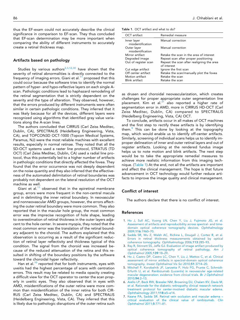
Table 1. OCT artifact and what to do?
OCT artifact Remedial measure
Inner layermisidentification
Manual correction
Outer layer Manual correction
86 J. Chhablani et al.
thus the EF-exam could not accurately describe the clinicalsignificance in comparison to EF-scan. They thus concludedthat EF-scan determination may be more important whencomparing the ability of different instruments to accuratelycreate a retinal thickness map.
misidentificationMirror artifact Retake the scan in the area of interestDegraded image Repeat scan after proper positioningOut of register scan Repeat the scan after realigning the area
of interestCut edge artifact Ignore the first scanOff center artifact Retake the scan/manually plot the foveaMotion artifact Retake the scanBlink artifact Retake the scan
Artifacts based on pathology
Studies by various authors2,3,12,30 have shown that theseverity of retinal abnormalities is directly connected to thefrequency of imaging errors. Giani et al.11 proposed that thiscould occur because the software tries to identify the normalpattern of hyper- and hypo-reflective layers on each single A-scan. Pathologic conditions lead to haphazard remodeling ofthe retinal segmentation that is strictly dependent on theseverity and the type of alteration. They observed, however,that the errors produced by different instruments were oftensimilar in certain pathologic conditions. They inferred that itwas likely because for all the devices, different layers wererecognized using algorithms that identified gray value varia-tions along the A-scan lines.
The authors concluded that CIRRUS (Carl Zeiss Meditec,Dublin, CA), SPECTRALIS (Heidelberg Engineering, Vista,CA), and TOPCON3D OCT-1000 (Topcon Medical Systems,Paramus, NJ) were the most reliable machines with excellentresults, especially in normal retinae. They noted that all theSD-OCT systems used a raster line protocol, STRATUS (TDOCT) (Carl Zeiss Meditec, Dublin, CA) used a radial line pro-tocol, thus this potentially led to a higher number of artifactsin pathologic conditions that directly affected the fovea. Theyfound that the error occurrence was not deeply dependenton the noise quantity and they also inferred that the effective-ness of the automated delimitation of retinal boundaries wasprobably not dependent on the lateral resolution of the OCTmachine as well.
Giani et al.11 observed that in the epiretinal membranegroup, errors were more frequent in the non-central maculaand in delimiting the inner retinal boundary. In neovascularand nonneovascular AMD groups, however, the errors affect-ing the outer retinal boundary were more common. They alsoreported that in the macular hole group, the most commonerror was the imprecise recognition of hole shape, leadingto overestimation of retinal thickness in the outer layers adja-cent to the hole center. In severe myopia, they noted that themost common error was the translation of the retinal bound-ary adjacent to the choroid. The authors explained that thisobservation is occurring as a result of the significant reduc-tion of retinal layer reflectivity and thickness typical of thiscondition. The signal from the choroid was increased be-cause of the reduced attenuation of the retina and this re-sulted in shifting of the boundary positions by the softwaretoward the choroidal hyper reflectivity.
Han et al.10 reported that for both instruments, eyes withuveitis had the highest percentage of scans with centrationerrors. This result may be related to media opacity creatinga difficult view for the OCT operator to center the scan prop-erly in uveitic eyes. They also observed that in eyes withAMD, misidentifications of the outer retina were more com-mon than misidentification of the inner retina for both CIR-RUS (Carl Zeiss Meditec, Dublin, CA) and SPECTRALIS(Heidelberg Engineering, Vista, CA). They inferred that thisis likely due to pathologic disruptions of the outer retina such
as drusen and choroidal neovascularization, which createschallenges for proper appropriate outer segmentation lineplacement. Kim et al.31 also reported a higher rate ofsegmentation error in AMD, more in CIRRUS HD-OCT (CarlZeiss Meditec, Dublin, CA) compared to SPECTRALIS(Heidelberg Engineering, Vista, CA) OCT.
To conclude, artifacts occur in all makes of OCT machinesand the first step to rectify these artifacts is by identifyingthem.9 This can be done by looking at the topographymap, which would enable us to identify off-center artifacts.Similarly, screening of individual scans helps us to identify im-proper delineation of inner and outer retinal layers and out ofregister artifacts. Looking at the rendered fundus imagehelps us to note motion and blink artifacts. The next stepwould be to take the appropriate remedial measures toachieve more realistic information from this imaging tech-nique. (Table 1) At the end, not all the artifacts are importantand affect the clinical management. The hope is that futureadvancement in OCT technology would further reduce arti-facts to improve the image quality and clinical management.
Conflict of interest
The authors declare that there is no conflict of interest.
References
1. Ho J, Sull AC, Vuong LN, Chen Y, Liu J, Fujimoto JG, et al.Assessment of artifacts and reproducibility across spectral- and time-domain optical coherence tomography devices. Ophthalmology2009;116:1960–70.
2. Sadda SR, Wu Z, Walsh AC, Richine L, Dougall J, Cortez R, et al.Errors in retinal thickness measurements obtained by opticalcoherence tomography. Ophthalmology 2006;113:285–93.
3. Ray R, Stinnett SS, Jaffe GJ. Evaluation of image artifact produced byoptical coherence tomography of retinal pathology. Am JOphthalmol 2005;139:18–29.
4. Ho J, Castro DP, Castro LC, Chen Y, Liu J, Mattox C, et al. Clinicalassessment of mirror artifacts in spectral-domain optical coherencetomography. Invest Ophthalmol Vis Sci 2010;51:3714–20.
5. Mitchell P, Korobelnik JF, Lanzetta P, Holz FG, Prunte C, Schmidt-Erfurth U, et al. Ranibizumab (Lucentis) in neovascular age-relatedmacular degeneration: evidence from clinical trials. Br J Ophthalmol2010;94:2–13.
6. Aiello LP, Beck RW, Bressler NM, Browning DJ, Chalam KV, Davis M,et al. Rationale for the diabetic retinopathy clinical research networktreatment protocol for center-involved diabetic macular edema.Ophthalmology 2011;118:e5–e14.
7. Keane PA, Sadda SR. Retinal vein occlusion and macular edema –critical evaluation of the clinical value of ranibizumab. ClinOphthalmol 2011;5:771–81.

Artifacts in optical coherence tomography 87
8. Mitry D, Bunce C, Charteris D. Anti-vascular endothelial growth factorfor macular oedema secondary to branch retinal vein occlusion.Cochrane Database Syst Rev 2013;1:CD009510.
9. Hee MR. Artifacts in optical coherence tomography topographicmaps. Am J Ophthalmol 2005;139:154–5.
10. Han IC, Jaffe GJ. Evaluation of artifacts associated with macularspectral-domain optical coherence tomography. Ophthalmology2010;117:1177–1189.e4.
11. Giani A, Cigada M, Choudhry N, Deiro AP, Oldani M, Pellegrini M,et al. Reproducibility of retinal thickness measurements on normaland pathologic eyes by different optical coherence tomographyinstruments. Am J Ophthalmol 2010;150:815–24.
12. Leung CK, Cheung CY, Weinreb RN, Lee G, Lin D, Pang CP, et al.Comparison of macular thickness measurements between timedomain and spectral domain optical coherence tomography. InvestOphthalmol Vis Sci 2008;49:4893–7.
13. Forooghian F, Cukras C, Meyerle CB, Chew EY, Wong WT. Evaluationof time domain and spectral domain optical coherence tomographyin the measurement of diabetic macular edema. Invest OphthalmolVis Sci 2008;49:4290–6.
14. Mylonas G, Ahlers C, Malamos P, Golbaz I, Deak G, Schuetze C, et al.Comparison of retinal thickness measurements and segmentationperformance of four different spectral and time domain OCT devicesin neovascular age-related macular degeneration. Br J Ophthalmol2009;93:1453–60.
15. Patel PJ, Chen FK, da Cruz L, Tufail A. Segmentation error in Stratusoptical coherence tomography for neovascular age-related maculardegeneration. Invest Ophthalmol Vis Sci 2009;50:399–404.
16. Sull AC, Vuong LN, Price LL, Srinivasan VJ, Gorczynska I, Fujimoto JG,et al. Comparison of spectral/Fourier domain optical coherencetomography instruments for assessment of normal macular thickness.Retina 2010;30:235–45.
17. Campbell RJ, Coupland SG, Buhrmann RR, Kertes PJ. Effect ofeccentric and inconsistent fixation on retinal optical coherencetomography measures. Arch Ophthalmol 2007;125:624–7.
18. Kraus MF, Potsaid B, Mayer MA, Bock R, Baumann B, Liu JJ, et al.Motion correction in optical coherence tomography volumes on a perA-scan basis using orthogonal scan patterns. Biomed Opt Express2012;3:1182–99.
19. Kim JS, Ishikawa H, Sung KR, Xu J, Wollstein G, Bilonick RA, et al.Retinal nerve fibre layer thickness measurement reproducibilityimproved with spectral domain optical coherence tomography. Br JOphthalmol 2009;93:1057–63.
20. Baskin DE, Gault JA, Vander JF, Dugan Jr JD. Double fovea artifact.Ophthalmology 2011;118:429.e1.
21. Ricco S, Chen M, Ishikawa H, Wollstein G, Schuman J. Correctingmotion artifacts in retinal spectral domain optical coherencetomography via image registration. Med Image Comput ComputAssist Interv 2009;12:100–7.
22. Hillmann D, Bonin T, Luhrs C, Franke G, Hagen-Eggert M, Koch P,et al. Common approach for compensation of axial motion artifacts inswept-source OCT and dispersion in Fourier-domain OCT. OptExpress 2012;20:6761–76.
23. Browning DJ, Fraser CM, Propst BW. The variation in opticalcoherence tomography-measured macular thickness in diabeticeyes without clinical macular edema. Am J Ophthalmol2008;145:889–93.
24. Diabetic Retinopathy Clinical Research Network, Krzystolik MG,Strauber SF, Aiello LP, Beck RW, Berger BB, et al. Reproducibilityof macular thickness and volume using Zeiss optical coherencetomography in patients with diabetic macular edema.Ophthalmology 2007;114:1520–5.
25. Wolf-Schnurrbusch UE, Ceklic L, Brinkmann CK, Iliev ME, Frey M,Rothenbuehler SP, et al. Macular thickness measurements in healthyeyes using six different optical coherence tomography instruments.Invest Ophthalmol Vis Sci 2009;50:3432–7.
26. Arevalo JF, Lasave AF, Arias JD, Serrano MA, Arevalo FA. Clinicalapplications of optical coherence tomography in the posterior pole:the 2011 Jose Manuel Espino Lecture – Part II. Clin Ophthalmol2013;7:2181–206.
27. Arevalo JF, Lasave AF, Arias JD, Serrano MA, Arevalo FA. Clinicalapplications of optical coherence tomography in the posterior pole:the 2011 Jose Manuel Espino Lecture – Part I. Clin Ophthalmol2013;7:2165–79.
28. Fung AE, Lalwani GA, Rosenfeld PJ, Dubovy SR, Michels S, Feuer WJ,et al. An optical coherence tomography-guided, variable dosingregimen with intravitreal ranibizumab (Lucentis) for neovascular age-related macular degeneration. Am J Ophthalmol 2007;143:566–83.
29. Lalwani GA, Rosenfeld PJ, Fung AE, Dubovy SR, Michels S, Feuer W,et al. A variable-dosing regimen with intravitreal ranibizumab forneovascular age-related macular degeneration: year 2 of thePrONTO Study. Am J Ophthalmol 2009;148:43–58.e1.
30. Karam EZ, Ramirez E, Arreaza PL, Morales-Stopello J. Opticalcoherence tomographic artefacts in diseases of the retinal pigmentepithelium. Br J Ophthalmol 2007;91:1139–42.
31. Kim M, Lee SJ, Han J, Yu SY, Kwak HW. Segmentation error andmacular thickness measurements obtained with spectral-domainoptical coherence tomography devices in neovascular age-relatedmacular degeneration. Ind J Ophthalmol 2013.