Bentleyuser.dk Årsmøde 2012 Nordic Civil 2012 · Bentleyuser.dk Årsmøde 2012 Nordic Civil 2012...
39
Bentleyuser.dk Årsmøde 2012 Nordic Civil 2012 Bentley Civil Workshop X09 Power Railtrack Presented by: Richard Bradshaw, BSW Development, Civil Design
-
Upload
trinhduong -
Category
Documents
-
view
216 -
download
0
Transcript of Bentleyuser.dk Årsmøde 2012 Nordic Civil 2012 · Bentleyuser.dk Årsmøde 2012 Nordic Civil 2012...

Bentleyuser.dk Årsmøde 2012 Nordic Civil 2012
Bentley Civil Workshop
X09 Power Railtrack
Presented by: Richard Bradshaw, BSW Development, Civil Design

Workshop: - X09 Power Railtrack Copyright © 2012 Bentley Systems, Inc.
This page left intentionally blank.

Preface The bulk of this workshop will be on turnouts and turnout advanced topics. You will learn how to create new turnouts in the turnout library. In addition, you will learn the differences between the Swiss and German rules for turnout bending. What are standard sleeper sets and how are they used. You will learn how to create a vertical alignment though a crossover. Also, we will investigate several obscure project options related to turnouts and how to use them. In addition, since regression analysis is such an important topic, we will learn how to use single element regression to create multiple alignments simultaneously.
In this workshop, we will use Power Rail Track V8i 08.11.07.594 or later.
In order for all participants to design the same layout and to stay on course and on time, we request that all participants utilize the files as listed in the workshop materials. At the beginning of each chapter, we will start with a fresh set of data. This ensures that everyone is using the same data. Plus, we have added data to avoid redundant work.
The workshop guide is yours to take with you. If you don’t finish all the exercises, or just want to work with the dataset upon return to your office, the datasets (both initial and completed files) are provided on the Conference DVD. Many workshops will also have videos of all exercises on the DVD.
Note Prerequisite Knowledge Level: Participant should have a basic understanding of rail design and has used Bentley Rail Track or Bentley Power Rail Track.

4 Workshop: - X09 Power Railtrack Copyright © 2012 Bentley Systems, Inc.
This page left intentionally blank.

Chapter 1: Multi-Alignment Single Element Regression
OVERVIEW All users of Power Rail Track should be well versed in the functionality for the creation of horizontal alignments from regression points. A typical workflow is as followings:
• Use File > Text Import Wizard and import regression points as cogo points • Use Horizontal Regression > Add Horizontal Regression Point and create a
horizontal regression buffer from the cogo points by applying selection and sorting criteria
• Use Horizontal Regression > Curvature Diagram and review the regression points and remove questionable data
• Use Horizontal Regression > Edit / Review Horizontal Regression Points and the Select & Regress option to single element regress the obvious lines and circular arcs
• Use Horizontal Elements > Define Spiral and fill in the gaps with spirals • Finally, use Horizontal Regression > Multiple Element Regression Analysis and fine
tune the geometry
The result is a horizontal alignment, but sometimes the user has more than one track and wishes to create parallel tracks. In this lesson, we will use regression data from two tracks and create both tracks simultaneously. We will have the following results:
• Tangents will be parallel • Circular arcs will be parallel • Transition spirals will be in filled • The offset will not be constant from one element to another
PROJECT DESCRIPTION In this workshop, we will simultaneously construct two parallel horizontal alignments using single element regression.
GETTING STARTED In this lesson, we load the data, view the regression points and then create the two tracks using single element regression. But first, create a Project Default and load the .xin and the turnout.txt that is included in the workshop’s data/ folder.
Exercise: Using Horizontal Regression Analysis
Exercise Objective: Simultaneously create multiple horizontal alignments from regression points
Procedure:

Getting Started
6 Workshop: - X09 Power Railtrack Copyright © 2012 Bentley Systems, Inc.
1. Open the file Chapter 1.dgn. 2. Open the file Regression.alg. 3. Use Horizontal Regression > View Horizontal Regression Points and display each track’s
regression points
4. Use Horizontal Regression > Curvature Diagram and display a curvature diagram for the active alignment Track 1
5. Invoke the Horizontal Regression > Edit / Review Horizontal Regression Points.
In the Regression Points list view, do a right click and you will see the typical popup menu with Insert, Edit and Delete. Dismiss the pop-up. Now, hold down <Ctrl> and again do a right click. The menu is now different! You now have the following:
• Select All • Select None • Delete Last Element(s) • Add Transition Spirals • A list of all horizontal alignments that have horizontal regression points
Note The software will use the active horizontal alignment and any other related alignments that you select from the pop-up. Remember we will only use two in this exercise, but the software will use as many as you wish.

Workshop: - X09 Power Railtrack 7 Copyright © 2012 Bentley Systems, Inc.
6. From the pop-up, right click Track 2 7. We will now use Select & Regress and select the tangents and circular arcs from the
curvature diagram. As always, follow the prompts i. Identify first point
ii. Identify second point iii. Accept / Reject
8. Before exiting the command, let’s again do a <Ctrl> right click and select the Add Transition Spirals. Now we have two alignments that have regressed tangents / circular arcs and we have filled in the gaps with spirals.
Note The software will use the default spiral type as defined in File > Project Options.
9. To review the results, go to Horizontal Regression > Slew Diagram and display a slew diagram for the active alignment
10. Let’s use a tool that you may not be familiar with and review the track centers. Go to Drafting > ProRail Extensions > View Track Centers command. From the dialog
• Set Track 1 as the Primary Alignment • Set Track 2 as the Secondary Alignment • Define an interval of 25 meters
Note If the Drafting > ProRail Extensions commands do not show up then go to Rail Track Tools > Application Addins and select it.
11. Click Apply and review the results.
Note The tracks are parallel, but the element’s offset vary from element to element.
CHAPTER SUMMARY In this chapter, we have learned how to use single element regression analysis to simultaneously create multiple horizontal alignments with lines, circular arcs and transition spirals.
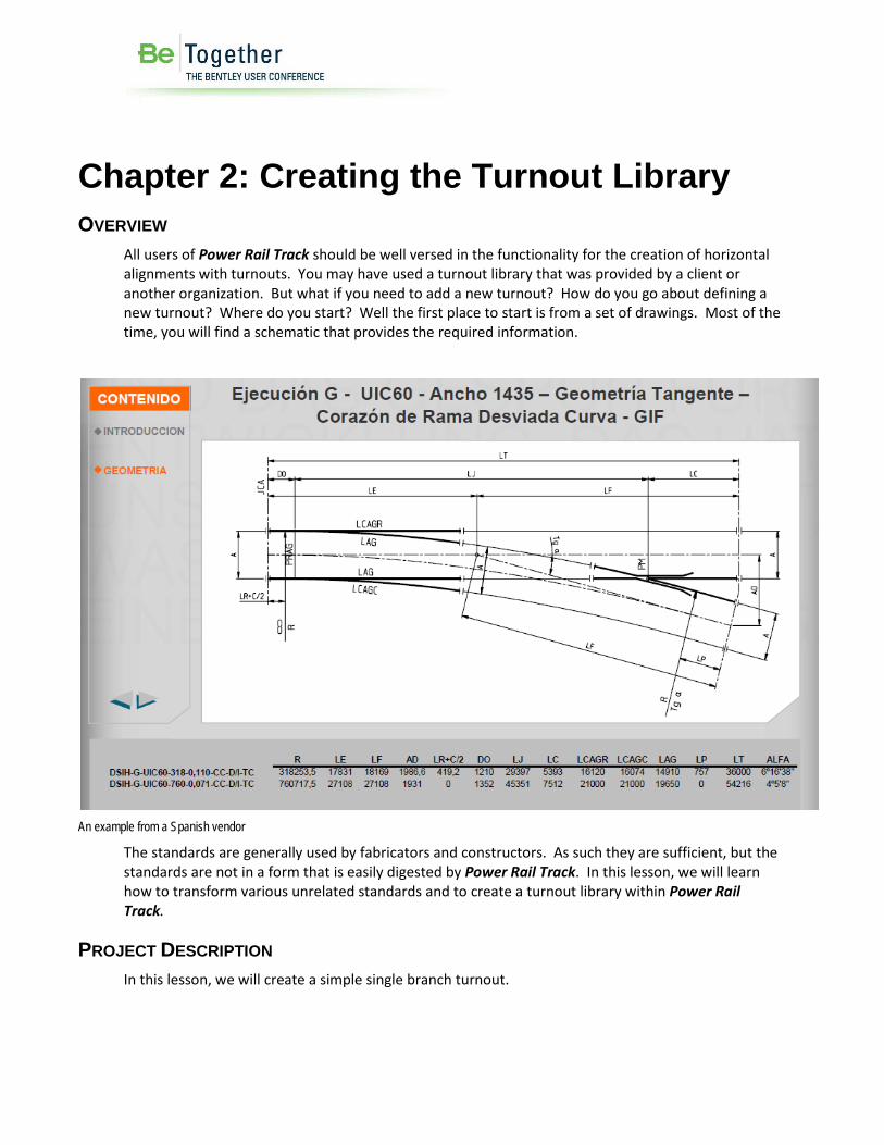
Chapter 2: Creating the Turnout Library OVERVIEW
All users of Power Rail Track should be well versed in the functionality for the creation of horizontal alignments with turnouts. You may have used a turnout library that was provided by a client or another organization. But what if you need to add a new turnout? How do you go about defining a new turnout? Where do you start? Well the first place to start is from a set of drawings. Most of the time, you will find a schematic that provides the required information.
An example from a Spanish vendor
The standards are generally used by fabricators and constructors. As such they are sufficient, but the standards are not in a form that is easily digested by Power Rail Track. In this lesson, we will learn how to transform various unrelated standards and to create a turnout library within Power Rail Track.
PROJECT DESCRIPTION In this lesson, we will create a simple single branch turnout.

Getting Started
Workshop: - X09 Power Railtrack 9 Copyright © 2012 Bentley Systems, Inc.
GETTING STARTED In this lesson, we will create a new single branch turnout in the current turnout library.
Exercise: Creating a new single branch turnout in the turnout library
Exercise Objective: Understand how to create a new single branch turnout in the turnout library
Procedure:
1. Open the file Chapter 2.dgn. 2. Go to Turnouts > Turnout Library
3. Click the Schematic button

Getting Started
10 Workshop: - X09 Power Railtrack Copyright © 2012 Bentley Systems, Inc.
Let’s understand what is displayed and what it all means.
Obviously the Name and Description allows the user to provide textual information about a turnout. The name will ultimately be assigned to a turnout’s style when an instance of the turnout is created in a Power Rail Track geometry project. The description will be assigned as the turnout’s description.
Note Once a turnout name has been defined and used within a geometry project, you should not rename or delete that turnout.
The type of turnout is whether the turnout is a single branch, a double branch, a single or double slip or a diamond crossing. The most common type is single.
Note that we start to see various numeric data, such as Length Along Mainline, Triangle Length and Ratio. Refer to the Schematic for how these numeric values relate to .1, .0, .2 and .3
Let’s skip down to the Branch Geometry group box. We see a list-view with element type, length and starting and ending radii. This allows the user to define each branch element as a linear, a circular arc or a spiral.
Note Power Rail Track supports various types of spirals. However, in the creation of turnouts the software will place with either clothoids or cubic parabolas. Cubic parabolas will be used only if the default spiral type is such in Project Options.
So when you start to collect the data for a new turnout, you need to look for the numeric data that is required on the dialog.
Let’s look at various turnout standards. Open the Windows Explorer and navigate to the various .pdf’s that are in the Chapter 2 folder.
It should be clear that various vendors / organizations provide the required numeric data in various forms. So let’s try to use it and create a new turnout.
Using the following let’s create a new turnout:

Getting Started
Workshop: - X09 Power Railtrack 11 Copyright © 2012 Bentley Systems, Inc.
4. Click the New button and define the following in the dialog and then click OK
5. On the Turnout Library dialog select the turnout that we just created and enter the following information
a. Theoretical .1 Length is 0.0 b. Mainline Length as 54.216 c. Triangle Length as 27.108 d. Ratio is 4 05 08 (switch from ratio to angle)
6. Now the branch elements. Right click in the branch geometry list-view and select Add to invoke the Add Turnout Branch Elements dialog.

Getting Started
12 Workshop: - X09 Power Railtrack Copyright © 2012 Bentley Systems, Inc.
7. We know we have a circular arc and we know the radius, but we don’t know the
circular arc length. But we do know the delta. So click the Curve Calc and define the radius as 760.0 and the delta as 4 05 08 and Compute and click OK.
Note The radius on the drawings is 760.7175 meters, which is measured to the outside rail. We want the centerline, so we need to adjust for half gauge.
8. On the Add Turnout Branch Element dialog we should have
12. Click Apply to add the element 13. Click Close on the Add Turnout Branch Element dialog 14. On the Turnout Library dialog, you should see the following:

Getting Started
Workshop: - X09 Power Railtrack 13 Copyright © 2012 Bentley Systems, Inc.
15. Click Apply to accept this turnout and to add it to the turnout library. 16. Click Close to exit the command.
Hint Sometimes, when you click Apply, you will get a warning “Turnout definition is inaccurate!” You will need to adjust the data to resolve the inaccurate warning. This is where you will need to make an engineering decision. What data is the most important and what data can be changed?

Getting Started
14 Workshop: - X09 Power Railtrack Copyright © 2012 Bentley Systems, Inc.
GETTING STARTED In this lesson, we will create a new double slip turnout in the current turnout library. We will use the DKW54 -190-1:9 defined in Chapter 2/ db_weichen_100dpi.pdf
As you can see we have the length along mainline, triangle length, ratio and we know radius from the turnout’s name.
Exercise: Create a new double slip turnout in the turnout library
Exercise Objective: Understand how to create a new double slip turnout in the turnout library
Procedure:
1. We will remain in the same .dgn and .alg for this lesson 2. Go to Turnouts > Turnout Library 3. Click the New button to invoke the New Turnout dialog
4. Change the type to Double Slip, enter a name and click OK 5. On the Turnout Library dialog select the double slip that you just created. Enter the
length along mainline, triangle length and ratio for each side of the slip and click Apply. You should see the following on the dialog:

Getting Started
Workshop: - X09 Power Railtrack 15 Copyright © 2012 Bentley Systems, Inc.
6. Okay, now we need to define the branch elements for each branch. Make sure that
the 1st Branch is selected and in the list-view click Add to invoke the Add Turnout Branch Element.
7. Again, we need to define element type, length and radii, but in this case we don’t really know the element lengths. So let’s use the curve calculator and compute what is needed. So click on Circular and then click the Curve Calc. to invoke the Curve Calculator dialog. The following:
8. Enter a radius of 190 9. Enter a delta of 6 20 24.69, now you see why I clicked Apply in step 5 above. We know
the ratio, but the curve calculator does not understand ratio. The curve calculator wants delta as an angle!
10. Click Compute

Getting Started
16 Workshop: - X09 Power Railtrack Copyright © 2012 Bentley Systems, Inc.
11. We want the tangent length 10.5232 meters and we want the circular arc’s length of
21.0249 meters click Cancel 12. On the Add Turnout Branch Element dialog, click the Linear radio button and enter a
length of 6.09180 meters, which is the triangle length minus the circular arc’s tangent (i.e. 16.615 – 10.5232)
13. Click Apply to add the linear 14. Now click the Circular radio button and enter a length of 21.0249 meters (i.e.
computed by the Curve Calculator) and a radius of 190 meters.
15. Click Apply to add the circular arc 16. And finally add the last linear by clicking Linear and defining the length as 6.0918
meters

Chapter Summary
Workshop: - X09 Power Railtrack 17 Copyright © 2012 Bentley Systems, Inc.
17. Click Apply and Close to exit the dialog 18. Click the 2nd branch and defined the exact same data for the second branch. When
you have finished, the Turnout Library dialog should look like the following:
19. Click Apply to save the double slip turnout into the turnout library 20. Click Close to exit the dialog.
CHAPTER SUMMARY In this chapter, we have learned how to create single and double slip turnouts in the turnout library.

Chapter 3: Turnout Bending Methods OVERVIEW
In the previous lesson, we created a single branch turnout from standard drawings. That turnout can now be used and the resultant geometry will be a circular arc with a length of 54.193 meters and a radius of 760 meters, provided it is placed onto a linear element. What happens if that turnout is placed onto a circular arc? The resultant geometry will be bent or flexed based upon rules. The software uses two different sets of rules for bending. They are the Swiss and German rules.
The Swiss rule (i.e. it is called Default on the user interface) is simply:
Rf = ( Rm x Rb ) / ( Rm +/- Rb )
Where;
Rf is the resultant flexed radius
Rm is the mainline radius
Rb is the branch radius as defined in the turnout library
The Swiss rule also states that the length along mainline is measured along the mainline alignment’s centerline. Also the rule allows the user to set that the mainline length is applied to the centerline, the outside rail or the inside rail. The default is centerline, but some organizations clearly state that the length is along one of the rails.
The Swiss rule results in the following:
• Length along mainline held o Can be applied to inner or outer rail
• Coordinate Positions o .1, .2, .0 and .3 held
• Tangential Directions o .1 tangential compromised o .2 tangential held o .3 tangential held o Multi-element branch geometry is not always collinear
The German rule is simply:
Rf = ( Rm x Rb - T2 ) / ( Rm +/- Rb )
Where
Rf is the resultant flexed radius
Rm is the mainline radius
Rb is the branch radius as defined in the turnout library

Project Description
Workshop: - X09 Power Railtrack 19 Copyright © 2012 Bentley Systems, Inc.
T is the sub-tangent length, which is the triangle length in a simple one element turnout, placed wholly within a circular element.
The German rule also states that the length along the mainline is measured along the mainline alignment’s sub-tangents. Yes, that means that the length along the centerline will be shortened!
Maintains
• Length along mainline held, but it is interpreted as the sub-tangent length not the centerline length!
• Coordinate Positions o .1, .2, .0 and .3 held
• Tangential Directions o .1 tangential held o .2 tangential held o .3 tangential held o Multi-element branch geometry is usually collinear
PROJECT DESCRIPTION In this lesson, we will investigate the Swiss and German rules for turnout bending.
GETTING STARTED In this lesson, we will investigate the Swiss and German rules for turnout bending.
Exercise: Investigating the Swiss and German rules for turnout bending.
Exercise Objective: Understand the differences between the Swiss and German turnout bending rules.
Procedure:
1. Open the file Chapter 3.dgn 2. Open the file Turnout Bending.alg 3. Go to Turnouts > Turnout Library and select the turnout that was previously created. 4. Click the Copy option and copy this turnout and give it a name of UIC60-760-0,071 German
and then Close.

Getting Started
20 Workshop: - X09 Power Railtrack Copyright © 2012 Bentley Systems, Inc.
5. Now select the UIC60-760-0,071 German turnout and change it from Default to German
Note The bending method is on each turnout, which means that you can mix Swiss and German bending into the same turnout library
6. Click Apply and click Close to exit the dialog 7. Let’s used the defined turnouts to create several crossovers and then review the results. 8. Go to Turnouts > Create Turnout
9. We will create a UIC60-760-0,071 on Track 1 at station 0+600. Set all values as shown and click Apply to create the new turnout.
10. Click Close to exit the dialog 11. Go to Turnouts > Create Connection to create the crossover

Getting Started
Workshop: - X09 Power Railtrack 21 Copyright © 2012 Bentley Systems, Inc.
Note We are going to create a simple crossover from Track 1 to Track 2 from the previously created turnout UIC60-760-0,071
12. Click Interactive, we could create the crossovers from the dialog, but this method is quicker. At the prompts:
1. Identify turnout and select Turnout 1 2. Identify mainline alignment and select Track 2 3. Accept / Reject and accept the solution
13. We will repeat the steps 9 through 13 and create crossover using the UIC60-760-0,071 German turnout.
14. Go to Turnouts > Create Turnout and define the following:
15. Click Apply and Close to exit the dialog 16. Go to Turnouts > Create Connection and define the following:
17. Click Interactive and select Turnout 3 and Track 2 to create the new crossover

Chapter Summary
22 Workshop: - X09 Power Railtrack Copyright © 2012 Bentley Systems, Inc.
Swiss ruled turnouts on the left and German ruled turnouts on the right
18. Now let’s review the results. Go to Turnouts > Reports
19. Select all of the turnouts by right clicking in the list-view and selecting Select All 20. Click Apply 21. In the Civil Report Browser select the turnouts.xsl and let’s review the results.
Method Turnout Length along Mainline
Mainline Radius (Rm)
T Branch Length
Bend Radius (Rf)
Equation
Swiss 1 54.216 1000.000 n/a 54.158 431.818 Rf = ( Rm x Rb ) / ( Rm + Rb )
Swiss 2 54.216 995 n/a 54.228 3217.872 Rf = ( Rm x Rb ) / ( Rm – Rb )
German 3 54.203 1000.000 27.108 54.114 431.401 Rf = ( Rm x Rb - T2 ) / ( Rm + Rb )
German 4 54.203 995 27.108 54.215 3220.999 Rf = ( Rm x Rb - T2 ) / ( Rm – Rb )
Gathered from several reports
CHAPTER SUMMARY In this chapter, we have learned the differences between the Swiss and German bending rules.

Chapter Summary
Workshop: - X09 Power Railtrack 23 Copyright © 2012 Bentley Systems, Inc.

Chapter 4: Standard Sleeper Sets OVERVIEW
Now that we have defined the Swiss and German bending methods, we can now look at sleeper sets. A sleeper set is a standard set of sleepers that will be placed at the end of the turnout geometry (i.e. at .2 and .3). All that we know about a standard sleeper set is a length and whether the sleeper set is linear or circular.
So what is the difference between a linear and circular sleeper set? Primarily it has to do how the geometry is constructed.
A linear sleeper set will match the mainline geometry. So if we place a 10 meter linear sleeper set onto a mainline radius of 1000 meter then the sleeper set will have a 1000 meter radius.
A circular sleeper set will bent the geometry using the Swiss or German rules. So the resultant radius will be less than or greater than 1000 meters, depending upon whether it is bent to the inside or outside.
PROJECT DESCRIPTION In this lesson, we will learn about standard sleeper sets
GETTING STARTED In this lesson, we will modify the UIC60-760-0,071 in the turnout library and define a circular sleeper set. We will then place that turnout and let the software create the standard sleeper set geometry.
Exercise: Modifying a turnout to include a circular sleeper set.
Exercise Objective: Modifying a turnout to include a circular sleeper set.
Procedure:
1. Open the file Chapter 4.dgn 2. Open the file Standard Sleeper Set.alg 3. Go to Turnouts > Turnout Library 4. Select the UIC60-760-0,071 turnout 5. Set Circular Sleeper Set as 5 meters 6. Set Distance to Last Long Sleeper to 5 meters
Note A standard sleeper set and distance to last long sleeper are both optional. You can have neither, one without the other, or both.

Chapter 4: Standard Sleeper Sets
Workshop: - X09 Power Railtrack 25 Copyright © 2012 Bentley Systems, Inc.
7. Click Apply and then Close to exit the dialog. 8. Create two new turnouts using the UIC60-760-0,071 turnout. You can refer back to the
Chapter 3 for how to create a simple crossover. Once you have created the crossover invoke the Turnouts > Connection Editor command.

Chapter Summary
26 Workshop: - X09 Power Railtrack Copyright © 2012 Bentley Systems, Inc.
Let’s take a look at what appears on the dialog and specific the standard sleeper set and last long sleeper. The Standard Sleeper Set is set to None and the Sleeper Set Length is 0.0 meters. Let’s proceed to create the standard sleeper set elements.
9. Set the Standard Sleeper Set for each turnout to Circular and the software will set the Sleeper Set Length to 5.0 meters (remember that is what we added in the turnout library). You will notice as we added the standard sleeper set elements that the connection has lengthened!
10. Click Apply to recompute the connection. You will notice that the original connection element had a length of 15.963 meters and a radius of 1008.800 meters has been recomputed.
11. Click Report… and let’s look at the results
The first element after the first turnout is defined as a circular arc with a length of 5.0 meters and a radius of 431.818 meters. The length of 5.0 meters is the standard sleeper length and since we defined it as a circular sleeper set then we would expect the radius to match the .3 radius. And it does!
The next element is also a circular arc of length 5.040 meters and a radius of 1034.641 meters.
The third element is the trailing turnout’s sleeper set. Again it is 5.0 meters in length and the radius is 3217.872 meters
CHAPTER SUMMARY In this chapter, we have learned about standard sleeper sets.

Chapter 5: Project Options and Turnouts
OVERVIEW In this lesson we will look at several ways to override and affect the crossover geometry. In Chapter 3, we read that the turnout geometry may not always be collinear. But, we can attempt to force the geometry to be collinear.
It should be noted that when we are talking about a turnout’s colinearity, we are talking about the branch elements. The software will always force the first element outside the branch (i.e. the element after .3) to be collinear. How? The software will use the direction from .0 to .3 as the first element’s entrance tangential direction.
Another issue is related to what happens when the mainline is canted. The turnout will be canted based upon the mainline. But the crossing is generally a fixed angle, so should the crossing angle be adjusted to account for cant?
The software provides options for accomplishing both of these. Whether you need to do is up to you!
PROJECT DESCRIPTION In this workshop, we will learn about options that affect the turnout’s geometry.
GETTING STARTED In this lesson, we will learn how to attempt to force a turnout to be collinear.
Exercise: Forcing turnout colinearity.
Exercise Objective: How to attempt to force a turnout to be collinear.
Procedure:
1. Open the file Chapter 5.dgn 2. Open the file Forced Collinearity.alg 3. Go to File > Project Options and the Rail tab

Getting Started
28 Workshop: - X09 Power Railtrack Copyright © 2012 Bentley Systems, Inc.
4. Check on Maintain Turnout Branch Element Colinearity 5. Click Apply and then click Close to exit the dialog 6. Go to Turnouts > Connection Editor 7. Select the crossover for alignment 1-2, by selecting turnout 1 8. Keep the dialog up and go to Geometry > Review Horizontal and select the same
crossover. You will see between the first and second elements, we have a non-collinear warning.
Note We have a 15 second difference in the directions, which equates to an offset of 2 millimeters over the length of the tangent of the turnout!
9. On the Connection Editor don’t change anything, just click Apply. Since we have checked on Maintain Turnout Branch Element Colinearity, the software will re-compute the geometry.
10. Click Save to save the recomputed geometry 11. Now look at the Review Horizontal alignment dialog. 12. The first element’s radius has changed from 431.818 meters to 431.401 meters and the
non-collinear warning has gone away. The software will adjust the branch radius to force colinearity at .3.
13. If we take a look at a second example, select the crossover 3-4 by selecting turnout 3. Essentially repeat steps 8 through 12. In this case, the first element’s radius has changed from 3217.872 meters to 3221.042 meters and the non-collinear warning has gone away.

Chapter 5: Project Options and Turnouts
Workshop: - X09 Power Railtrack 29 Copyright © 2012 Bentley Systems, Inc.
Exercise: Should I consider cant when computing turnouts?
Exercise Objective: Investigate the affects of computing a turnout based upon the mainline’s cant
Procedure:
14. We will remain in the same .dgn and .alg for this lesson 15. Go to File > Project Options and the Rail tab
16. Check on Compute Turnouts Based on Mainline Cant 17. Click Apply and then click Close to exit the dialog. 18. Go to the Turnout > Connection Editor 19. Select the crossover for alignment 1-2, by selecting turnout 1

Chapter Summary
30 Workshop: - X09 Power Railtrack Copyright © 2012 Bentley Systems, Inc.
20. Note that the existing connecting element, which was computed without adjusting for cant, has a length of 15.963 meters and a radius of 1008.770 meters.
21. Click Apply, so that the crossover is recomputed and adjusts for cant. The software has recomputed the connecting element with a length of 16.039 meters and a radius of 1008.734 meters. More importantly, the software has maintained the turnout’s cross angle along the track plane, thus flattening the angle on the horizontal plane.
Note It should be clear that in the case of enforce colinearity; the software did not change the .1, .0, .2 or .3. The software held those critical points. However, when the software adjusted for cant the coordinates and tangential direction at .3 changed.
CHAPTER SUMMARY In this chapter, we have learned how to force a turnout’s to have collinear branch geometry. As well as, how to take into consideration the mainline alignment’s cant in computing turnout horizontal position.


Chapter 6: Connection Editor OVERVIEW
In a previous lesson, we created a crossover by using the Create Connection command. While this command is quick and easy, sometimes that is not enough. Or sometimes the design needs to be changed and you need a more robust tool. The Connection Editor is that tool.
The Connection Editor will allow the user to edit an existing connection. The following:
Selecting a turnout will invoke an existing crossover. So making a simple edit like moving a turnout up station by 10 meters is simply changing the starting station and clicking Apply to re-compute.
Selecting a turnout and changing it from one turnout style to another turnout style. Again just selecting the turnout invokes the previous connection and you simply change the turnout’s style and re-compute.
PROJECT DESCRIPTION In this workshop, we will learn about the Turnout Connection Editor.

Chapter 6: Connection Editor
Workshop: - X09 Power Railtrack 33 Copyright © 2012 Bentley Systems, Inc.
GETTING STARTED In this lesson, we will learn how to edit a previously computed crossover.
Exercise: Editing a previously computed crossover
Exercise Objective: Edit a previously computed crossover’s starting station
Procedure:
1. Open the file Chapter 6.dgn 2. Open the file Connection Editor.alg 3. Go to the Turnout > Connection Editor
4. In this case we have selected turnout 1 and the software recalls the previous connection (as well as recalling the previous fixities).
5. Change the start station from 0+600 to 0+575, you will see that turnout 1 plus the connecting elements have moved.
6. Now click Apply and the software recomputes the entire crossover. 7. Now let’s see everything move in a more dynamic fashion. Again, we will be changing the
first turnout’s start station. But this time we will use the data point button, but when we select the data point click <Ctrl> at the same time. Now the entire crossover is placed in dynamics and everything is recomputed.

Getting Started
34 Workshop: - X09 Power Railtrack Copyright © 2012 Bentley Systems, Inc.
8. Accept or reject the dynamics. 9. Click Save to save the results and click Close to exit the dialog.
Hint If a turnout is defined with a theoretical .1 the station on the user interface is the .1 station. The geometry will start at the theoretical .1 and when it is created as a horizontal alignment it will start at the theoretical .1
Exercise: Editing a previous computed crossover
Exercise Objective: Edit a previously computed crossover’s by changing the turnout’s style
Procedure:
10. Continuing with the same data, go to the Turnout > Connection Editor 11. Change the beginning turnout’s style to e6050014 12. Change the ending turnout’s style to e6076014 13. Click Apply to re-compute the solution
14. Click Save to save the solution 15. Based upon previous lessons, what other edits could we make in the Turnout > Connection
Editor?
Hint If we refer back to Chapter 4, we discussed standard sleeper sets and last long sleepers. While we originally defined these within the

Chapter 6: Connection Editor
Workshop: - X09 Power Railtrack 35 Copyright © 2012 Bentley Systems, Inc.
turnout library, you could define a non-standard length sleeper set within the Turnout > Connection Editor. Just change the Standard Sleeper Set to Linear or Circular and define the Sleeper Set Length.
CHAPTER SUMMARY In this chapter, we have learned how to modify a previous defined crossover.

Chapter 7: Creating Verticals through Turnouts
OVERVIEW In this lesson, we will learn how to create a vertical alignment through a crossover. The software will use the turnout’s mainline alignment’s vertical alignment and cant alignments plus the offset from the mainline to the branch geometry (at an interval) to compute the turnout’s vertical. The intent is to project the mainline’s plane through to the plane of the turnout. We are also trying to ensure that there is a smooth transition from one turnout to the next.
PROJECT DESCRIPTION In this lesson, we will learn how to create a vertical alignment through a crossover.
GETTING STARTED In this lesson, we will learn how to create a vertical alignment through a crossover.
Exercise: Creating a vertical alignment through a crossover
Exercise Objective: Creating a vertical alignment through a crossover.
Procedure:
1. Open the file Chapter 7.dgn 2. Open the file Create Verticals.alg 3. Go to Turnouts > Create Verticals 4. Set the vertical name, description and style as shown. Set the number of segments to 16.
Also, toggle on compute from Second Mainline and check on Use Alternate Solver (Partially with Cant Transition)
5. Click Apply

Chapter 7: Creating Verticals through Turnouts
Workshop: - X09 Power Railtrack 37 Copyright © 2012 Bentley Systems, Inc.
Note Track NS (top) has a defined vertical alignment and a cant alignment. Track SN (bottom) has a cant alignment. Its vertical will be created from Track NS (top) and the crossover 1-2. Also, note that crossover 1-2 is wholly within a horizontal circular arc and crossover 5-6 is partially within a spiral / cant transition!
6. Click on the crossover 5-6 and create the vertical and cant alignment by clicking Apply 7. Click Close to exit the dialog 8. To review the results go to Evaluation > Create Profile. Create a profile for crossover 1-2
and 5-6 using an elevation range with a maximum elevation of 255 and a minimum elevation of 250. Also set the vertical exaggeration to 40
9. Go to Geometry > View Rails and select Project to Profile and select profile 1-2. Set the
settings as shown below.

Getting Started
38 Workshop: - X09 Power Railtrack Copyright © 2012 Bentley Systems, Inc.
10. Click Apply 11. Select horizontal alignment Track NS (top) and click Apply to project it onto the same
profile. 12. Likewise select horizontal alignment Track SN (bottom) and project it onto the same profile. 13. Since that crossover was placed wholly within a circular arc and cant was constant, you will
see that all rails are at a constant height above each other. 14. Now select the profile for 5-6 and project alignments 5-6, Track NS (top) and Track SN
(bottom) into the profile window. 15. Before reviewing the results, go to Turnouts > Display Turnouts in Profile. Select the
profile window for crossover 5-6, set the settings as shown below and click Apply

Chapter 7: Creating Verticals through Turnouts
Workshop: - X09 Power Railtrack 39 Copyright © 2012 Bentley Systems, Inc.
You can clearly see that turnout 6 is within a horizontal spiral and a corresponding cant transition. We have used Geometry > View Rails to project the rails onto a profile window. We could also have displayed the rails in plan (either as 2d or 3d) or appended them into a terrain model. In the case of the later, these could then be used as features within Roadway Designer.
CHAPTER SUMMARY In this chapter, we have learned how to create a vertical alignment through a crossover.