ARMMS - Diamond Field Effect Transistors · terminated diamond field effect transistors of varying...
8
1 DIAMOND FIELD EFFECT TRANSISTORS Stephen A.O. Russell*, Salah Sharabi*, Alex Tallaire†, Helen McLelland* and David A.J. Moran* * School of Engineering, University of Glasgow, Glasgow, United Kingdom. Contact: [email protected], Tel: +44 (0)141 330 3374 † LIMHP-CNRS, Université Paris 13, 99 Avenue Jean-Baptiste Clément, 93430 Villetaneuse, France ABSTRACT High-quality single crystal diamond has been used to demonstrate the RF performance of hydrogen- terminated diamond field effect transistors of varying gate lengths; this includes the first data on a sub- 100nm diamond transistor. The RF performance for 220nm, 120nm and 50nm gate length transistors was extracted and a cut-off frequency of 55 GHz was measured for the 50nm device. This is the highest value yet reported for any diamond based transistor. This significant increase can be attributed to the quality of the material, improved diamond growth techniques and device scaling. 1. INTRODUCTION Diamond has long been seen as the perfect material for high power electronics, with a material breakdown field of 10 MVcm -1 for pure single crystal diamond and thermal conductivity >2000 Wm -1 K -1 [1]. The large bandgap associated with diamond of 5.47eV makes it suitable for high voltage operation. If current difficulties with processing could be overcome then diamond could fill requirements for a niche market requiring robust high power and high frequency electronics for operation in harsh environments. Figure 1: Plot demonstrating the superior material qualities associated with diamond Along with power performance diamond can also offer competitive frequency performance. Velocity saturation occurs at ~ 1x10 7 cm.s -1 and low field mobility can reach up to 4500 and 3800 cm 2 V -1 s -1 for electrons and holes respectively [1].
Transcript of ARMMS - Diamond Field Effect Transistors · terminated diamond field effect transistors of varying...

1
DIAMOND FIELD EFFECT TRANSISTORS
Stephen A.O. Russell*, Salah Sharabi*, Alex Tallaire†, Helen McLelland* and David A.J. Moran*
* School of Engineering, University of Glasgow, Glasgow, United Kingdom. Contact: [email protected], Tel: +44 (0)141 330 3374
† LIMHP-CNRS, Université Paris 13, 99 Avenue Jean-Baptiste Clément, 93430 Villetaneuse, France
ABSTRACT High-quality single crystal diamond has been used to demonstrate the RF performance of hydrogen-terminated diamond field effect transistors of varying gate lengths; this includes the first data on a sub-100nm diamond transistor. The RF performance for 220nm, 120nm and 50nm gate length transistors was extracted and a cut-off frequency of 55 GHz was measured for the 50nm device. This is the highest value yet reported for any diamond based transistor. This significant increase can be attributed to the quality of the material, improved diamond growth techniques and device scaling. 1. INTRODUCTION Diamond has long been seen as the perfect material for high power electronics, with a material breakdown field of 10 MVcm-1 for pure single crystal diamond and thermal conductivity >2000 Wm-1K-1
[1]. The large bandgap associated with diamond of 5.47eV makes it suitable for high voltage operation. If current difficulties with processing could be overcome then diamond could fill requirements for a niche market requiring robust high power and high frequency electronics for operation in harsh environments.
Figure 1: Plot demonstrating the superior material qualities associated with diamond
Along with power performance diamond can also offer competitive frequency performance. Velocity saturation occurs at ~ 1x107 cm.s-1 and low field mobility can reach up to 4500 and 3800 cm2V-1s-1 for electrons and holes respectively [1].

2
Looking at some of its competitors and comparing them as seen in Figure 1, it is clear that in terms of intrinsic material properties diamond can match or better all of them. In comparison with gallium nitride (GaN) which can provide high power and high frequency operation, thermal management in diamond is far superior due to a thermal conductivity almost twenty times larger. This is a very attractive quality of diamond as high power inherently means high temperature operation and self heating can destroy device performance. The major challenges involved in working with diamond in active electronic components are the cost of growth, limited substrate size, difficulties in processing the material and dopant incorporation for room temperature operation. There has been steady progress in recent years with diamond growth. Chemical vapour deposition (CVD) processes can produce much higher quality single crystal diamond than ten years ago; also various forms of polycrystalline diamond are available as a cheaper alternative without necessarily sacrificing electronic performance. Processing of devices and doping remain the biggest challenges, with no shallow dopants yet found for substitutional doping of the diamond lattice. Moderate success has been achieved with boron for p-type doping although due to high activation energy (0.37eV) [2], large concentrations are required and this will substantially lower the carrier mobility. As yet n-type doping remains un-feasible for electronic applications with the shallowest donor being phosphorous at 0.6eV [3]. Diamond is limited in terms of dopant elements due to the strong covalent tetrahedral bonds of its lattice, inserting large elements will distort this structure and wreck the superior material qualities associated with it. An alternative is using an effect known as ‘surface transfer doping’ which utilizes the negative electron affinity (NEA) found at a hydrogen-terminated diamond surface [4]. 2. SURFACE TRANSFER DOPING Due to the large bandgap associated with intrinsic diamond it is naturally an insulator. The diamond surface can be terminated with various elements as the edge of a diamond lattice (carbon in a sp3 bonding configuration) leaves dangling bonds. The two most common gas species used for this purpose are oxygen and hydrogen. Oxygen is energetically preferable and gives an insulating surface whereas hydrogen will give the surface its NEA. This is in contrast to hydrogen being used to stabilize silicon or germanium surfaces. Carbon however is more electronegative than these elements i.e.: it has a stronger tendency to attract electrons due to only having two electron shells, meaning the attraction of it’s positive nucleus is stronger due to less distance between atoms. Oxygen is more electronegative than carbon and gives the surface a positive electron affinity. The NEA present at the hydrogen-terminated diamond surface lowers the ionization potential and means electrons will readily leave the surface if encouraged by a suitable electron accepting material as pictured in Figure 2. Various molecules present in the atmosphere will readily adsorb on to the diamond surface and draw electrons out leaving behind a sub-surface conductivity. Thus a very shallow p-type channel forms within ~10nm of the surface. This is very beneficial for fabricating high frequency devices as it gives the ability to modulate the channel charge density with a small gate contact. Issues of stability however are attributed to relying on atmospheric conditions to induce conductivity. Other compounds such as C60F48 have been shown to produce the same effect as these atmospheric adsorbates, but as yet none have been used in the fabrication of active electronic devices [5].

3
Figure 2: Surface transfer doping at the diamond surface via atmospheric adsorbates [4]. 3. FIELD EFFECT TRANSISTOR (FET) FABRICATION The diamond used in this work (supplied by Element Six) was single crystal with (001) orientation grown by microwave plasma CVD. After growth the diamond was cleaned, oxygen terminated and then hydrogen termination was performed (again in a microwave plasma CVD reactor). Due to the volatility of the hydrogen terminated diamond and the associated adsorbates, special care needs to be taken in fabrication of FETs. A gold ‘sacrificial layer’ was first deposited onto the surface to protect it during fabrication from electron beam exposure, elevated temperatures for resist baking and potential resist residue issues. Device fabrication involved a three step lithography process to define alignment markers on the substrate, electrically isolate the devices and finally define the gate and ohmic contacts. Figure 3 shows the process by which the gate and ohmic contacts are formed. The gate profile was patterned into resist on top of the gold sacrificial layer with an oxygen plasma ash used to remove resist residue from on top of the gold. A potassium iodide based etch was then used to over etch the gold, allowing deposition of the aluminium gate while at the same time defining the source-drain spacing. Finally lift-off in acetone was performed to remove resist and excess metal leaving the finished FETs.

4
Figure 3: Gate lithography procedure. The FETs were designed in a two finger gate configuration with gate lengths (Lg) of 220, 120 and 50nm all with a total width of 50µm. Co-planar measurement pads were employed for measurement with RF probes as shown in Figure 4.
Figure 4: Two finger gate FET along with co-planar measurement pads.
Source
Gate
Drain

5
4. DC PERFORMANCE & SCALING All DC analysis was done with drain voltage (Vd) varying from 0-10 volts. Gate voltage (Vg) was varied for each FET according to device dimensions. The 220nm Lg FET results are shown in Figure 5, with pinch-off of the drain current occurring at around +0.5Vg. A Vg of -3.5V could be applied with negligible gate leakage. This yielded a peak saturation current of -340 mA.mm-1. Looking at the transconductance plot, it peaks at 92 mS.mm-1 and plateaus between -1V to 2V Vg and between -7V to -10V Vds.
0 -2 -4 -6 -8 -100
-50
-100
-150
-200
-250
-300
-350 -3.5 Vgs -3.0 Vgs -2.5 Vgs -2.0 Vgs -1.5 Vgs -1.0 Vgs -0.5 Vgs +0.0 Vgs +0.5 Vgs +1.0 Vgs +1.5 Vgs +2.0 Vgs
Dra
in C
urre
nt (m
A.m
m-1)
Drain Voltage (V)2 1 0 -1 -2
0
10
20
30
40
50
60
70
80
90
100
0.0 Vds -1.0 Vds -2.0 Vds -3.0 Vds -4.0 Vds -5.0 Vds -6.0 Vds -7.0 Vds -8.0 Vds -9.0 Vds -10.0 Vds
Tran
scon
duct
ance
(mS.
mm
-1)
Gate Voltage (V)
Figure 5: DC performance of 220nm Lg FET. The 100nm Lg FET shown in Figure 6 still achieved good pinch-off, this time at Vg of +1.0V. Saturation current of -360mA.mm-1 could be achieved at a Vg of -2V. The transconductance similarly plateaus but at a higher value of 137mS.mm-1.
0 -2 -4 -6 -8 -100
-50
-100
-150
-200
-250
-300
-350
-400
-2.0 Vgs -1.5 Vgs -1.0 Vgs -0.5 Vgs +0.0 Vgs +0.5 Vgs +1.0 Vgs +1.5 Vgs +2.0 Vgs
Dra
in C
urre
nt (m
A.m
m-1)
Drain Voltage (V)
0 Vds -1 Vds -2 Vds -3 Vds -4 Vds -5 Vds -6 Vds -7 Vds -8 Vds -9 Vds -10 Vds
2 1 0 -1 -20
20
40
60
80
100
120
140
Tran
scon
duct
ance
(mS.
mm
-1)
Gate Voltage (V)
Figure 6: DC performance of 120nm Lg FET. Finally the 50nm Lg FET shown in Figure 7 did not quite reach pinch-off even at a Vg of +4V. A reasonable saturation current of -250 mA.mm-1 could still be achieved at a Vg of 0V. Transconductance was far lower at a value of 78 mS.mm-1 and reached its plateau from +1V to -0.5V Vg.

6
0 -2 -4 -6 -8 -100
-50
-100
-150
-200
-250 +0.0 Vgs +0.5 Vgs +1.0 Vgs +1.5 Vgs +2.0 Vgs +2.5 Vgs +3.0 Vgs +3.5 Vgs +4.0 Vgs
Dra
in C
urre
nt (m
A.m
m-1)
Drain Voltage (V)2 1 0 -1
0
10
20
30
40
50
60
70
80 0.0 Vds -1.0 Vds -2.0 Vds -3.0 Vds -4.0 Vds -5.0 Vds -6.0 Vds -7.0 Vds -8.0 Vds -9.0 Vds -10.0 Vds
Tran
scon
duct
ance
(mS.
mm
-1)
Gate Voltage (V)
Figure 7: DC performance of 50nm Lg FET. 5. RF PERFORMANCE The RF metric we investigated in this work was the cut-off frequency (fT) i.e. the point at which device current gain is equal to unity. Different bias points were chosen for the three different gate length FETs to match their peak transconductance. In the case of 220nm and 120nm Lg transistors a bias of -8Vds and -1Vg was chosen and in the case of the 50nm FET a bias point of -8Vds and -0.4Vgs was chosen. The cut-off frequency of each Lg FET is shown in Figure 8. The 220nm device had fT = 19 GHz, 120nm fT = 43 GHz and 50nm fT = 55 GHz. 6. DISCUSSION & CONCLUSIONS
1 10 600
10
20
H21
(dB)
Frequency (GHz)1 10 60
0
10
20
H21
(dB)
Frequency (GHz) (a) Lg = 220nm (b) Lg = 120nm

7
1 10 600
10
20
H21
(dB)
Frequency (GHz)
(c) Lg = 50nm
Figure 8: Cut-off frequency (fT) for 220, 120 and 50nm Lg FETs. The DC performance of these FETs changes with gate length as could be expected, the transconductance appears to increase until the 50nm Lg is reached at which point it markedly drops, possibly due to much larger access resistances in this device. As expected the value of fT increases with decreasing Lg. Although the 50nm Lg FET has a much lower transconductance the reduced gate capacitance leads to a fT of 55 GHz. This is the highest value yet reported for a diamond based transistor. Optimization will give improved performance with minimizing the access resistance being crucial [6]. Due to the nature of the fabrication process required to protect the volatile hydrogen-terminated surface ohmic contacts are not annealed hence contact resistance is high. Also the source-drain spacing is produced by a wet chemical etch which is unpredictable and leaves rough ohmic contact edges, meaning a varied source-drain separation. To improve the maximum frequency (fmax) of the devices, the fabrication of T-gates could be used to give a much lower gate resistance due to a larger cross-sectional area. The highest fmax reported thus far for a 100nm gate length device is 120 GHz [7]. Reducing this dimension to 50nm is expected to improve this. For diamond to truly realize its potential with regard to power electronics the hydrogen-terminated surface requires stabilization and passivation. Several avenues have been suggested for this including alternatives to the adsorbed atmospherics such as fluorinated fullerenes or similar high electron affinity electron accepting materials [5]. Although work has been done to show these can replace atmospheric adsorbates and give the p-type sub-surface channel little work has yet been performed fabricating devices from this. A suitable passivation layer could also lead to stabilization of the hydrogen-terminated diamond surface and increased power operation of devices. ACKNOWLEDGEMETNS
The author wishes to thank Element Six for supply of the material used in this work and the EPSRC for funding the project.
8
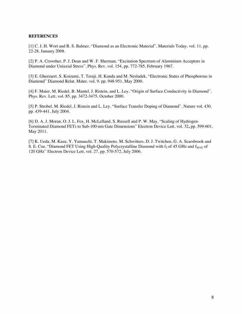
REFERENCES [1] C. J. H. Wort and R. S. Balmer, “Diamond as an Electronic Material”, Materials Today, vol. 11, pp. 22-28, January 2008. [2] P. A. Crowther, P. J. Dean and W. F. Sherman, “Excitation Spectrum of Aluminium Acceptors in Diamond under Uniaxial Stress”, Phys. Rev, vol. 154, pp. 772-785, February 1967. [3] E. Gheeraert, S. Koizumi, T. Teraji, H. Kanda and M. Nesladek, “Electronic States of Phosphorous in Diamond” Diamond Relat. Mater, vol. 9, pp. 948-951, May 2000. [4] F. Maier, M. Riedel, B. Mantel, J. Ristein, and L. Ley, “Origin of Surface Conductivity in Diamond”, Phys. Rev. Lett, vol. 85, pp. 3472-3475, October 2000. [5] P. Strobel, M. Riedel, J. Ristein and L. Ley, “Surface Transfer Doping of Diamond”, Nature vol. 430, pp. 439-441, July 2004. [6] D. A. J. Moran, O. J. L. Fox, H. McLelland, S. Russell and P. W. May, “Scaling of Hydrogen-Terminated Diamond FETs to Sub-100-nm Gate Dimensions” Electron Device Lett, vol. 32, pp. 599-601, May 2011. [7] K. Ueda, M. Kasu, Y. Yamauchi, T. Makimoto, M. Schwitters, D. J. Twitchen, G. A. Scarsbrook and S. E. Coe, “Diamond FET Using High-Quality Polycrystalline Diamond with fT of 45 GHz and fMAX of 120 GHz” Electron Device Lett, vol. 27, pp. 570-572, July 2006.