ARFFS fire fighting vehicles - CTIFctif.no/uploads/French RFFS Fire Fighting Vehicle...
52
©Copyright CNMSA Page 1 on 52 National commission for airport safety equipments Project / Operation: Technical specifications Reference: 004/2005 Version: V2R5 date 13/07/2006 Author: Jean Luc THIRION Ministère de l’Intérieur et Ministère de l’Ecologie du Developpement et de l’Aménagement Durable ARFFS fire fighting vehicles Common technical specifications Contact: Service Technique de L’Aviation Civile Centre de Toulouse 1, avenue du Dr. Maurice Grynfogel BP 53584 31035 Toulouse cedex Phone: + 33 5 62 14 59 72 Fax: + 33 5 62 14 54 66 email: jean-luc.thirion @aviation-civile.gouv.fr
Transcript of ARFFS fire fighting vehicles - CTIFctif.no/uploads/French RFFS Fire Fighting Vehicle...
©Copyright CNMSA Page 1 on 52
National commission for airport safety equipments
Pro ject / Operat ion : Technical specif icat ions
Reference : 004/2005
Vers ion : V2R5 date 13/07/2006
Author : Jean Luc THIRION
Ministère de l’Intérieur et
Ministère de l’Ecologiedu Developpement et de l’AménagementDurable
ARFFS fire fighting vehicles
Common technical specifications
Contact:Service Technique deL’Aviat ion Civ i le
Centre de Toulouse
1, avenue du
Dr. Maurice Grynfogel
BP 53584
31035 Toulouse cedex
Phone:
+ 33 5 62 14 59 72
Fax:
+ 33 5 62 14 54 66
email : jean-luc .thir ion@aviation-civi le.gouv.fr

CNMSA Project Technical specifications Version V2R5
Title SSLIA vehicles – Common technical specifications Date 13/07/2006
©Copyright CNMSA Page 2 on 52
Document history
Document version
Date written Reason for revision Author
1.0 14/08/2002 First draft after workgroup No. 1 meetings 1 and 2 JL THIRION
1.1 15/11/2002 Summary after workgroup No. 1 meetings 3 and 4 JL THIRION
1.2 31/01/2003 Summary after workgroup No. 1 meeting 5 JL THIRION
1.3 10/04/2003 Final draft after proof reading by WG members JL THIRION
1.4 10/09/2003 Project corrected following CNMSA (I/2003) JL THIRION
1.5 03/10/2003 Project corrected following CNMSA (II/2003) JL THIRION
1.6 03/11/2003 Corrections following material errors – Published version (May 23 2004 order)
JL THIRION
2.0 25/03/2005 Preparation of change No. 1 JL THIRION
2.1 05/08/2005 Summary after workgroup No. 4 meeting 1 JL THIRION
2.2 23/11/2005 Summary after workgroup No. 4 meeting 2 JL THIRION
2.3 22/02/2006 Final draft after CNMSA (I/2005) JL THIRION
2.4 18/04/2006 Corrections following material errors JL THIRION
2.5 13/07/2006 Final draft after CNMSA (I/2006) - Published version (Janvier 2nd 2007 order)
JL THIRION
CNMSA Project Technical specifications Version V2R5
Title SSLIA vehicles – Common technical specifications Date 13/07/2006
©Copyright CNMSA Page 3 on 52
Table of contents
1 INTRODUCTION ....................................................................................................... 71.1 Document presentation 7
1.2 Definitions 7
1.3 Standard references 8
2 GENERAL ............................................................................................................... 102.1 Scope 10
2.2 Usage conditions 10
2.3 Weather conditions during use 10
2.4 Corrosion 11
2.5 General characteristics 11
2.6 Road performances 11
2.7 Mobility 12
2.8 Center of gravity 12
2.9 Gauge 12
3 CHASSIS AND MOTORDRIVE ............................................................................... 133.1 Motordrive 13
3.2 Transmission 13
3.3 Weight distribution 13
3.4 Chassis geometric characteristics 14
3.5 Brakes 14
3.6 Suspensions 15
3.7 Greasing 15
3.8 Tires 15
3.9 Endurance 16
3.10 Towing 16
3.11 Protection against falling objects 16
3.12 Onboard package 16
4 BODYWORK........................................................................................................... 174.1 General 17
4.2 Cab 17
4.2.1 Driving compartment 17
4.2.2 Doors 18
4.2.3 Door frames and support handles 18
4.2.4 Access to the cab from the floor ground 18

CNMSA Project Technical specifications Version V2R5
Title SSLIA vehicles – Common technical specifications Date 13/07/2006
©Copyright CNMSA Page 4 on 52
4.2.5 Indoors seats 18
4.2.6 Access to the operating station platform 18
4.3 External compartments 19
4.3.1 Access to equipment 19
4.3.2 Fitting 19
4.4 Protection 20
4.4.1 Paint 20
4.4.2 Anti-underride guard 20
4.4.3 Miscellaneous 20
5 ELECTRICAL EQUIPMENT.................................................................................... 215.1 Installation 21
5.1.1 General 21
5.1.2 Current generator 21
5.1.3 Batteries 21
5.1.4 Main switch 22
5.1.5 Lighting and external signaling 22
5.1.6 Internal lighting 22
5.2 radiophone equipment 22
5.2.1 Preliminary wiring and installation 22
5.2.2 Anti-interference 22
5.3 Electrical switchgear 23
5.3.1 Low voltage connector 23
5.3.2 Special sirens and marking lighting 23
5.3.3 Special lights 23
5.3.4 Heating engines 24
5.3.5 Heating tanks 24
5.3.6 Cold zone 24
6 HYDRAULIC INSTALLATION................................................................................. 256.1 General 25
6.2 Pump 25
6.2.1 General 25
6.2.2 Flow 25
6.3 Hydraulic circuit pressurization principle 26
6.3.1 Pump driven by separate motor (called « power-driven pump ») 26
6.3.2 Pump drive by the traction engine 26
6.3.3 Propulsion of foam solution by propellant gas 27
6.4 Supply and discharge orifices 27
6.5 Water tank 27
6.6 Foam concentrate tank 28

CNMSA Project Technical specifications Version V2R5
Title SSLIA vehicles – Common technical specifications Date 13/07/2006
©Copyright CNMSA Page 5 on 52
6.7 Proportioning system 29
6.8 Turret nozzle 29
6.9 Foam handlines 30
6.10 bumper turret 31
6.11 Front monitor on articulated boom 31
6.12 Undertruck nozzles 31
6.13 Reel 32
6.14 Quality of foams obtained 32
7 DRY CHEMICAL INSTALLATION .......................................................................... 337.1 General 33
7.2 Propellant agent 33
7.3 Use of the propellant agent 33
7.4 Modifications to the content of propellant gas cylinders 34
7.5 Dry chemical tank 34
7.6 Dry chemical handline 34
7.7 Blowing 34
8 MANEUVER AND CONTROL INSTRUMENTS, DOCUMENTS.............................. 358.1 The cab 35
8.1.1 Visible and accessible from the driver's seat 35
8.1.2 Visible and accessible from the driver's seat and the operator's seat 36
8.2 The operating station platform 37
8.3 operating stations of lateral foam hoses 37
8.4 The additional discharge (DN 65) control station 37
8.5 Changes to standby mode 38
8.5.1 If the turret nozzle power assistance malfunctions 38
8.5.2 If the valve power assistance malfunctions 38
8.5.3 If the automatic control malfunctions 38
8.6 Rinsing cycle 39
8.7 Priority of pressures 39
8.8 Identification and instruction plates 39
8.9 Documents 40
9 COMPLIANCE TESTS: ROAD PART (1/2)............................................................. 419.1 CHARACTERIZATION by weight 41
9.2 Vehicle general performance 41
9.3 Vehicle stability 41
9.3.1 Static stability 41
9.3.2 Dynamic stability 41
9.3.3 NATO AVTP test 42
9.3.4 SAE test J2181 42

CNMSA Project Technical specifications Version V2R5
Title SSLIA vehicles – Common technical specifications Date 13/07/2006
©Copyright CNMSA Page 6 on 52
9.4 Braking 42
9.5 Performances 42
9.6 Clearance circle diameter between walls 42
10 COMPLIANCE TESTS: OTHER TESTS (2/2) ....................................................... 4310.1 General 43
10.2 Motordrive 43
10.3 Bodywork 43
10.4 Electrical equipment 44
10.5 Hydraulic installation 44
10.6 Dry chemical equipment 46
10.7 Instruments (chapters 8.1 TO 8.8) 46
11 COMPOSITION OF THE COMPLIANCE APPLICATION FILE ............................. 4711.1 Part 1: use 47
11.2 Part 2: vehicle technical file 47
11.3 part 3: tests 48
12 APPENDIX A: MODIFICATIONS OR MAIN / MINOR VARIATIONS.................... 4912.1 Major modifications 49
12.2 Minor Modifications 49
13 APPENDIX B: BUYERS GUIDE............................................................................ 50

CNMSA Project Technical specifications Version V2R5
Title SSLIA vehicles – Common technical specifications Date 13/07/2006
©Copyright CNMSA Page 7 on 52
1 INTRODUCTION
1.1 DOCUMENT PRESENTATION
The purpose of this document is to collect common technical specifications for fire fighting vehicles used in ARFFS (Aircraft Rescue and Fire Fighting Services), in application of article D.213.1.7 in chapter III, book II of the Civil Aviation Code (part 3). It is applicable to these vehicles under the conditions defined by the National commission for airport safety equipments.
The requirements defined in this document must be understood as being minimums in terms of performance, safety and ease of use. Depending on the technical constraints specific to his application, a buyer may define more severe or complementary requirements for his own needs.
This document also describes compliance check tests to be performed on vehicles before they can be declared as compliant with specifications by the National commission for airport safety equipment. These tests will be carried out under conditions defined by the commission. They must not be confused with « acceptance » tests in which a buyer checks that the delivered equipment is conforming to his order.
A guide for buyers is given for information (chapter 13) so as to summarize the different points to be specified during an order for an ARFF vehicle.
1.2 DEFINITIONS
The definitions in documents S60-101-4, S60-101-8, NF EN 1846-1, NF EN 1846-2, NF EN 1846-3 and XP S 61-518 are applicable except for:
• Spray stream: used to replace « fog stream », due to the risk of confusion with other « fog » water devices.
• Usable capacity of a tank: quantity of liquid contained in a tank that can be used for discharging by the main nozzle of the vehicle (turret nozzle) at the nominal flow rate of this nozzle until the first time that the pump is unprimed.
The following definitions are also applicable specifically to ARFF vehicles:
• Hydraulic installation: system composed of storage containers, hydraulic elements and control and instrumentation equipment for supplying the various nozzles on a foam making vehicle with the foam solution in the required percentage, and at the required flow and pressure depending on the required performances.
• Water tank: storage container installed on a vehicle and containing water used to produce the foam solution.
• Foam concentrate tank: storage container installed on a vehicle and containing the foam concentrateused to produce the foam solution.
Note: the water and foam concentrate tanks are usually combined in a single physical assembly called the « tank », but this is not mandatory in these specifications.
CNMSA Project Technical specifications Version V2R5
Title SSLIA vehicles – Common technical specifications Date 13/07/2006
©Copyright CNMSA Page 8 on 52
• Turret nozzle: main nozzle on a foam making vehicle. The regulations require that only foam solutionflows produced by this nozzle (and the corresponding usable water capacity) are considered to determine the equipment to be supplied to an aerodrome to provide the required protection level.
• Bumper turrets, foam handlines: complementary nozzles, the flows available with those nozzles are not used to determine the equipment to be installed on an aerodrome to satisfy the required protection level.
• Undertruck nozzles: protection by discharging on the ground with the purpose of protecting the entire vehicle when passing over burning elements and/or pools of fuel (not to be confused with the «thermal protection» in standard XP S 61-518).
• Dry chemical installation: system composed of one (or several) storage containers, mechanical elements and control and instrumentation equipment in order to supply dry chemical to the dry chemicalhandline, at the required pressure in order to meet the required performances.
• Dry chemical handline: nozzle to discharge dry chemical. Only nozzle for vehicles fitted only with dry chemical (VIP).
• Driver: ARFFS personnel who can access the vehicle driving controls and fire fighting equipment controls from his seat.
• Operator: ARFFS personnel who can access fire fighting equipment controls from his seat. The operator may also need to get off the vehicle to use handlines or other equipment or accessories while the driver remains in the cab, or he may need to go to the operating station platform to use the vehicle in standby mode.
• Passenger: any other person(s) transported in the cab. These passengers do not need access to the controls and indicators for using the vehicle.
• Operating station platform: operating station for using the turret nozzle in standby mode.• Operating stations on the ground: operating stations for using foam handlines, the 65 mm additional
discharge pipe, suction from the outside or the dry chemical handline.• Standby mode: vehicle usage mode in which one (or several) automations or power assistance
nozzles available on the vehicle are defective. In these modes, the vehicle remains useable, but wholly or partly using manual control nozzles. Therefore the operational efficiency of work on an accident is necessarily lower in these modes.
• Standby manual control: the standby manual control may be done by a mechanical, electrical, pneumatic or hydraulic system or directly by manual force applied by the ARFFS personnel. These controls are used to double up an automatic control when there is one. However, standby powerassistance controls only rely on manual force applied by the ARFFS personnel.
1.3 STANDARD REFERENCES
List of standards mentioned or used in this document. The presence of a standard in this list does not suggest that the standard is applicable to ARFFS vehicles. Unless mentioned otherwise, all standard references refer to the most recent version of the text given for reference (update on 18/05/2006)
• S60-101-4: Fire fighting – Vocabulary – Part 4 Fire extinction equipment.• S60-101-8: Fire protection – Vocabulary – Part 8 Terms specific to fire fighting and rescue services and
handling of hazardous materials.• NF ISO 2575 Road vehicles – Symbols for controls, indicators and warning lights.• PR NF ISO 10085 Fire fighting vehicles and equipment – Symbols for operator controls and other
displays.• NF EN 418 Safety of machinery – Emergency stop equipment, functional aspects – Principles for design.

CNMSA Project Technical specifications Version V2R5
Title SSLIA vehicles – Common technical specifications Date 13/07/2006
©Copyright CNMSA Page 9 on 52
• NF EN 659 Protective gloves for firefighters.• NF X 08.008 Colors – Fire red.• NF EN 60529 Degrees of protection provided by enclosures (IP code).• NF EN 1846-1 Fire Fighting and rescue vehicles – Part 1: Nomenclature and designation.• NF EN 1846-2 Fire Fighting and rescue vehicles – Part 2: Common requirements – Safety and
performances • NF EN 1846-2/A1 Fire Fighting and rescue vehicles – Part 2: Common requirements – Safety and
performance.• NF EN 1846-3 Fire Fighting and rescue vehicles – Part 3: Permanently installed equipment – Safety and
performance.• XP S 61-518 Fire Fighting and rescue vehicles – Firefighting and rescue appliance – CCF type pumping
appliance.• NF S 61-112 Fire fighting equipment. Discharge flexible hoses 25-36,5-45-70-110 MM diameters.• NF S 61-112/A1 Fire fighting equipment. Discharge flexible hoses 25-36,5-45-70-110 MM diameters.• NF EN 1947 Fire fighting hoses – Semi-rigid delivery hoses and hose assembling for pumps and
vehicles.• NF EN 14557 Fire fighting hoses – Rubber and plastic suction hoses and hose assemblies.• NF EN 1028-1 Fire fighting pumps – Fire fighting centrifugal pumps with primer– Part 1: Classification –
General and safety requirements.• NF EN 1028-2 Fire fighting pumps - Fire fighting centrifugal pumps with primer – part 2: Verification of
general safety requirements.• NF S 61-702 Fire fighting equipment - Types of coupling used.• NF S 61-704 Fire fighting equipment – Self sealing symmetric half-couplings size 40 and 65.• NF S 61-705 Fire fighting equipment - Self sealing symmetric half-couplings size 100 – Type AR.• NF S 61.706 Fire fighting equipment – Position of the lugs or jaws on Guillemin-type self-sealing
symmetric couplings.• NF E 29.572 Quarter turn connection (Guillemin system) – PN 16.
CNMSA Project Technical specifications Version V2R5
Title SSLIA vehicles – Common technical specifications Date 13/07/2006
©Copyright CNMSA Page 10 on 52
2 GENERAL
2.1 SCOPE
The applicant (in the sense used in chapter 5 of the regulations for processing compliance certificate applications) is responsible for the vehicle design, construction and performances and for any sub-assembly even if it is subcontracted, except for products imposed by the buyer. He must assure that all elements supplied are new. He must assure that the vehicle and its permanently installed equipment is capable of satisfying these specifications and European or French regulations or standards in force, and in particular the following (non-exhaustive list):• European directives related to road vehicles;• European directives related to pressurized equipment;• European directives related to machines (so-called « safety of machinery » directives) ;• European directives related to low voltage electrical equipment;• Automobile Standardization Office Standards;• Electricity and Technical Union Standards;• Highway Code (apart from exceptions specified in note 25698, 1/10/1996).
When imposed by standards and regulations in force (see above), compliance of a vehicle, as promulgated by the National commission for airport safety equipments, remains subordinate to approval by organizations or the addition of CE marks for permanently installed equipment or for subassemblies on this vehicle.
For example, it remains subordinate to approval by the DRIRE (Regional Directorate of Industry, Research and the Environment) (e.g. Mines Service) for putting the vehicle on the road.
Consequently, compliance with these specifications does not necessarily imply compliance with requirements in the standards and directives mentioned above. Nor does it offer a pretext for avoiding satisfying them. However, although the standard reference for rescue and fire fighting vehicles (NF EN 1846-1, NF EN 1846-2, NF EN 1846/A1 and NF EN 1846-3) is not applicable to ARFFS vehicles, these specifications include references to the relevant sections in these standards whenever necessary.
2.2 USAGE CONDITIONS
These vehicles are designed for aircraft fire fighting on the ground. In accordance with the regulations, they may be used on an aerodrome and its immediate surroundings, on runways or surfaced tracks or non-pavedareas, during the day or night.
In order to simplify the use of foam making vehicles, fire fighting equipment must be provided with a automation system for the main functions including pressure regulations, and an automatic function to rinse the nozzles. They must be provided with a power assistance system for operation of the valves, and in some cases a power assistance system for handling the turret nozzle.
This automation system and these power assistance systems shall be provided with controls to enable a return to manual use of all operational functions of the vehicle.
2.3 WEATHER CONDITIONS DURING USE
These vehicles will be put into service on aerodromes in a wide variety of climates, such that vehicles, electronic systems and all connections have to be adapted to climatic conditions of use.
CNMSA Project Technical specifications Version V2R5
Title SSLIA vehicles – Common technical specifications Date 13/07/2006
©Copyright CNMSA Page 11 on 52
The climatic conditions of use are classified into three categories:• Cold zone: - 40°C to + 15°C ;• Temperate zone: - 15°C to + 35°C ;• Hot zone: + 15°C to + 60°C.
Vehicles are designed for use with standard industrial quality water.
2.4 CORROSION
Manufacturers’ attention is drawn particularly to the fact that these vehicles are frequently exposed to the weather under a variety of climatic and geographic conditions. Furthermore, due to conditions of use and personnel training, all this equipment is exposed to contact with extinguishing solutions with various different aggressiveness. A global surface treatment adapted to corrosion risks and dependent on the weather conditions in which the vehicles are used, shall be applied after complete assembly of the fire equipment on the cabin chassis subassembly.
Therefore, the manufacturer shall take special care with problems that arise due to corrosion of the chassis, metallic elements of the bodywork and fire fighting equipment. It is recommended that materials not severely affected by corrosion, stratified polyester and other plastic composites should be used.
Chapter 5.2.5 in NF standard EN 1846-2 is applicable for resistance to corrosion. The estimated life specified by the user shall be greater than or equal to 10 years.
2.5 GENERAL CHARACTERISTICS
Vehicles are coded by a group of letters and numbers, beginning with VI to denote a crash rescue vehicle and followed whenever necessary by:- the letter M for foam followed by the number of hundreds of liters of water available (usable water
quantity) for production of this foam, possibly rounded;- the letter P for dry chemical, followed by the number of hundreds of kilograms of dry chemical, possibly
rounded.
The vehicle code is indicated when the compliance certificate is issued.
Examples:- VIM 90 P 2.5: vehicle containing 9 000 liters of water usable for the production of foam and 250 kg of dry
chemical;- VIP2.5: vehicle containing 250 kg of dry chemical.
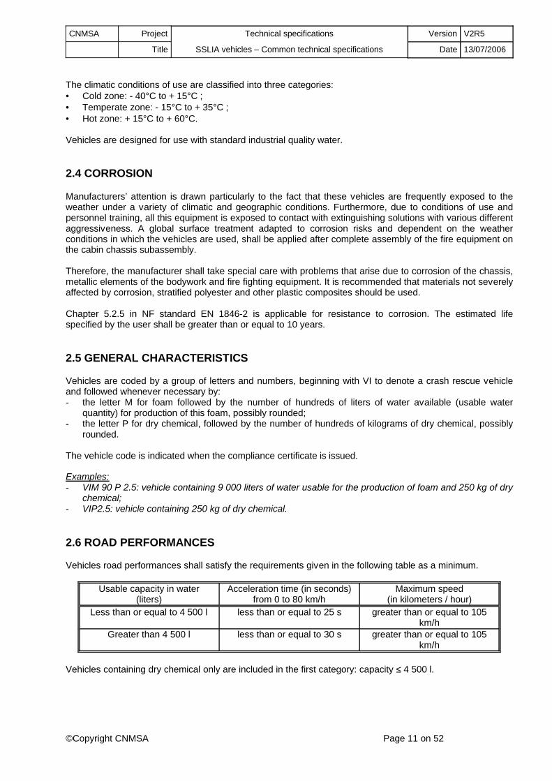
2.6 ROAD PERFORMANCES
Vehicles road performances shall satisfy the requirements given in the following table as a minimum.
Usable capacity in water(liters)
Acceleration time (in seconds) from 0 to 80 km/h
Maximum speed(in kilometers / hour)
Less than or equal to 4 500 l less than or equal to 25 s greater than or equal to 105 km/h
Greater than 4 500 l less than or equal to 30 s greater than or equal to 105 km/h
Vehicles containing dry chemical only are included in the first category: capacity ≤ 4 500 l.
CNMSA Project Technical specifications Version V2R5
Title SSLIA vehicles – Common technical specifications Date 13/07/2006
©Copyright CNMSA Page 12 on 52
It is prohibited to limit the speed of vehicles by construction (note 25698 date 1/10/1996 issued by the Ministry of Transport to the DRIREs (Regional Directorate of Industry, Research and Environment) summarizing various exeptions to the Highway Code applicable to rescue and fire fighting vehicle).
2.7 MOBILITY
All vehicles shall be constructed using single wheels (in other words with no dual wheels) and all wheels will be driving wheels. They shall be equipped with differential locking devices or any other equivalent equipment. They are used with independent control for locking between axles, between rear wheels and between front wheels.
Locking between front wheels shall depend on permanent action by the driver. However, a control without permanent action by the driver may be accepted provided that its use triggers a non-disengageable visual and sound alarme. Furthermore, this locking between wheels is not required for a vehicle with a total grossweight of less than 3.5 Tonnes.
2.8 CENTER OF GRAVITY
Stability must be optimized, firstly due to the high power of engines installed on aircraft rescue and fire fighting vehicles, and secondly due to the urgent conditions under which these vehicles are required to operate on aerodromes. Consequently, their center of gravity must be as low as possible while respecting:- the geometric characteristics of the chassis defined in these specifications;- the size defined in these specifications;- the maximum height of the center of gravity of the chassis with respect to the load distribution during
braking.
Vehicles shall have successfully passed the dynamic stability tests defined in this document (chapter 9).
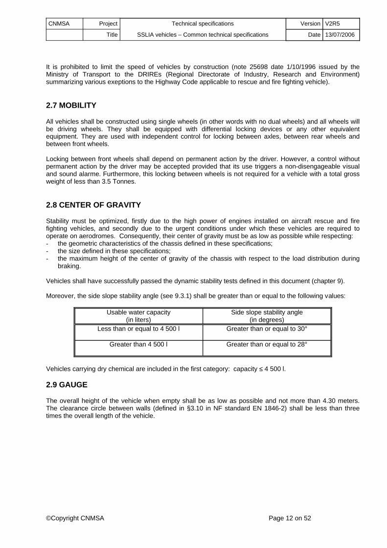
Moreover, the side slope stability angle (see 9.3.1) shall be greater than or equal to the following values:
Usable water capacity(in liters)
Side slope stability angle(in degrees)
Less than or equal to 4 500 l Greater than or equal to 30°
Greater than 4 500 l Greater than or equal to 28°
Vehicles carrying dry chemical are included in the first category: capacity ≤ 4 500 l.
2.9 GAUGE
The overall height of the vehicle when empty shall be as low as possible and not more than 4.30 meters. The clearance circle between walls (defined in §3.10 in NF standard EN 1846-2) shall be less than three times the overall length of the vehicle.
CNMSA Project Technical specifications Version V2R5
Title SSLIA vehicles – Common technical specifications Date 13/07/2006
©Copyright CNMSA Page 13 on 52
3 CHASSIS AND MOTORDRIVE
3.1 MOTORDRIVE
The engine(s) conforming to French or European standards (as defined in the DRIRE report) shall be powerful enough for the vehicle to satisfy the required road and/or hydraulic performances for the vehicle as defined in these specifications. Its equipment shall enable start-up and normal operation at an ambient temperature within the limits specified for the usage zone of the vehicle at an altitude of less than 600 meters.
Gas exhausts from the engine(s) shall be arranged such that there is no risk of causing intoxication or burns for personnel working at operating stations during normal use of the vehicle. When exhaust pipes are in the lower part on the vehicle, they shall be provided with spark guards to prevent sparks being projected onto the ground.
The engines are fitted with a heating device. Engine compartments at the back of the chassis and separate engines (power-driven pumps) are provided with an emergency stop circuit breaker preventing use (even from the cab), in accordance with NF standard 418, class O (mushroom shaped red button, with no key, on yellow background, identified « emergency stop »).
Vehicles with a total gross weight of more than 3.5 Tonnes that are provided with an automatic hydraulic installation regulation system, shall be provided with a standby manual accelerator for the power-driven pump. This device shall be identified and sealed for a mechanical control, and in all cases the speed thus controlled by the driver shall remain stable without continuous action on the control.
Start prevention systems (anti-theft device) are not allowed, and if necessary they shall be disassembled or completely disabled.
3.2 TRANSMISSION
The gearbox is automatic for vehicles with a total gross weight of more than 3.5 Tonnes.
Vehicles are provided with a siren and a visual alarme system at the back, that operate whenever reverse gear is selected and are conforming with chapter 5.1.1.8 in NF EN 1846-2, regardless of the total grossweight.
3.3 WEIGHT DISTRIBUTION
The total weight of the fully loaded vehicle shall be distributed as equally as possible between the different axles and wheels, to assure good stability and a good motor drive with the vehicle in all configurations. To achieve this, this distribution shall respect the following criteria (loaded vehicles) for vehicles with a usablewater capacity of more than 4 500 liters:
- the difference in weight between the wheels on the same axle and for each axle shall not exceed 5% of the average weight per wheel of this axle.
- the weight difference between any two axles shall not exceed 10% of the weight of the heaviest axle, if the heaviest axle is the rear axle. This maximum difference is reduced to 5%, if the heaviest axle is the front axle.

CNMSA Project Technical specifications Version V2R5
Title SSLIA vehicles – Common technical specifications Date 13/07/2006
©Copyright CNMSA Page 14 on 52
Only the first criterion is required for vehicles with a usable water capacity of 4 500 liters or less.Vehicles carrying dry chemical only are included in the category : capacity ≤ 4 500 l.
3.4 CHASSIS GEOMETRIC CHARACTERISTICS
The geometric characteristics of the chassis with the loaded vehicle shall be as follows, to not hinder displacement of the vehicle off the road:
Usable water capacity Less than or equal to 4 500 l Greater than 4 500 l
Approach and departure angles(in degrees)
Greater than or equal to 30 ° Greater than or equal to 30 °
Ramp angle (in degrees)
Greater than or equal to 24 ° Greater than or equal to 24 °
Ground clearance and ground clearance under axles
(in meters)
Greater than or equal to 0.20 m Greater than or equal to 0.33 m
Diagonal opposite wheel motion(in meters)
Greater than or equal to 0.25 m Greater than or equal to 0.35 m
Vehicles carrying dry chemical only are included in the first category: capacity ≤ 4 500 l.The definition of the approach and departure angles, the ramp angle, ground clearance, ground clearance under axles and the diagonal opposite wheel motion are given in standard NF EN 1846-2, chapters 3.4 to 3.9.
3.5 BRAKES
The braking system shall be conforming to European Directive 71/320/CEE or the French regulations in force if the French regulations are more severe. Brakes are power assisted. The power assistance may be pneumatic, hydraulic or hydropneumatic. Braking is applied on all wheels and the system is designed such that a break in any one pipe will not cause total loss of the braking capacity. The design of the vehicle braking system shall be such that it also enables another vehicle stop, even when the engine is not running (this requirement is not applicable to vehicles with a total gross weight of less than 3.5 Tonnes).
The braking system shall be sufficiently leaktight to remain operational (in other words with the chassis safety device not activated) for 2 hours with the engine cut off, vehicle not connected to an auxiliary energy source and onboard electro-compressor deactivated. The parking brake shall be sufficient to keep the vehicle immobile at full load in a 20% slope.
During normal operation, the system must be capable of stopping the vehicle at full load under the following conditions:
CNMSA Project Technical specifications Version V2R5
Title SSLIA vehicles – Common technical specifications Date 13/07/2006
©Copyright CNMSA Page 15 on 52
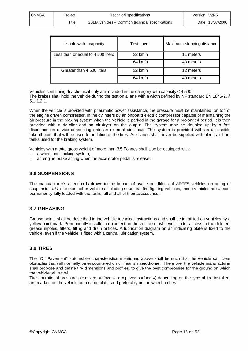
Usable water capacity Test speed Maximum stopping distance
Less than or equal to 4 500 liters 32 km/h 11 meters
64 km/h 40 meters
Greater than 4 500 liters 32 km/h 12 meters
64 km/h 49 meters
Vehicles containing dry chemical only are included in the category with capacity ≤ 4 500 l.The brakes shall hold the vehicle during the test on a lane with a width defined by NF standard EN 1846-2, § 5.1.1.2.1.
When the vehicle is provided with pneumatic power assistance, the pressure must be maintained, on top of the engine driven compressor, in the cylinders by an onboard electric compressor capable of maintaining the air pressure in the braking system when the vehicle is parked in the garage for a prolonged period. It is then provided with a de-oiler and an air-dryer on the output. The system may be doubled up by a fast disconnection device connecting onto an external air circuit. The system is provided with an accessible takeoff point that will be used for inflation of the tires. Auxiliaries shall never be supplied with bleed air from tanks used for the braking system.
Vehicles with a total gross weight of more than 3.5 Tonnes shall also be equipped with:- a wheel antiblocking system;- an engine brake acting when the accelerator pedal is released.
3.6 SUSPENSIONS
The manufacturer’s attention is drawn to the impact of usage conditions of ARFFS vehicles on aging of suspensions. Unlike most other vehicles including structural fire fighting vehicles, these vehicles are almost permanently fully loaded with the tanks full and all of their accessories.
3.7 GREASING
Grease points shall be described in the vehicle technical instructions and shall be identified on vehicles by a yellow paint mark. Permanently installed equipment on the vehicle must never hinder access to the different grease nipples, filters, filling and drain orifices. A lubrication diagram on an indicating plate is fixed to the vehicle, even if the vehicle is fitted with a central lubrication system.
3.8 TIRES
The "Off Pavement" automobile characteristics mentioned above shall be such that the vehicle can clear obstacles that will normally be encountered on or near an aerodrome. Therefore, the vehicle manufacturer shall propose and define tire dimensions and profiles, to give the best compromise for the ground on which the vehicle will travel.Tire operational pressures (« mixed surface » or « pavec surface ») depending on the type of tire installed, are marked on the vehicle on a name plate, and preferably on the wheel arches.

CNMSA Project Technical specifications Version V2R5
Title SSLIA vehicles – Common technical specifications Date 13/07/2006
©Copyright CNMSA Page 16 on 52
3.9 ENDURANCE
The capacity of the fuel tank shall be sufficient to satisfy the stricter of the following two conditions:- a distance of 200 km on a road with a medium rough profile;- operation of the fire fighting equipment at its nominal characteristics for two hours.
The tank filling orifice shall be easily accessible to standard equipment used for this purpose, including the use of a jerrican. An indicating plate fixed nearby indicates the nature of the fuel.
3.10 TOWING
Vehicles shall be equipped with a towing device at the front and the back. Applicable forces shall correspond to the total weight of the gross vehicle. If shackles are used, each shackle and its attachment shall resist a tension force equal to half of the total allowable gross weight.
3.11 PROTECTION AGAINST FALLING OBJECTS
Manufacturers’ attention is drawn to the fact that in an aeronautical context, the loss of objects on runways leads to serious consequences. Consequently, the installation of protection devices (casings, nets, etc.) should be considered to limit the risk of objects getting lost on the runways.
3.12 ONBOARD PACKAGE
The vehicle shall be provided with the following minimum onboard equipment:• A tool kit,• a jack with bar and jack extension,• a tire-nuts wrench for changing the wheel,• a set of spare fuse for all models,• an inflation hose with an inflation handle and accessories (couplings, etc.) for use of an external air
supply or for a connection onto a braking circuit (vehicles with pneumatic power assisted braking),• an approved red-warning triangle.
These elements are not necessarily installed onboard the vehicle.

CNMSA Project Technical specifications Version V2R5
Title SSLIA vehicles – Common technical specifications Date 13/07/2006
©Copyright CNMSA Page 17 on 52
4 BODYWORK
4.1 GENERAL
The chassis cab assembly and the fire fighting equipment shall be as compact as possible, with no accessories projecting outside the general outline of the vehicle if they could create a risk of impact on persons moving around the vehicle, when working or while parking.
Extension of any element that goes outside the gauge of the vehicle (retractable steps, compartment doors, etc.) shall be identified by a visual alarme in the cab. § 5.1.2.1 in NF standard EN 1846-2 is applicable.
4.2 CAB
4.2.1 Driving compartment
The cab shall be accessible to the operator(s) and shall not have any aggressive element at the accesses. Whenever necessary, the cab is equipped with a protection on the windshield (and under the front grille) against runoff of the foam. Glazed surfaces of the cab shall limit the effects of solar radiation, in accordance with the Highway Code. If there is a central driving position, the two sides of the cab shall be fitted with three rear view mirrors. In a tilting type cab, tilting shall be possible without disassembly of any of the equipment elements and without any external lifting device.
There shall be at least two seats (the driver's seat and an operator's seat) for vehicles with a total grossweight of more than 3.5 Tonnes. The number of seats in other vehicles is for one person (the driver). In both cases, additional seats may only be passenger places (neither driver nor operator).
The cab roof shall be provided with one or several transparent parts to enable visualisation of the turret nozzle in all positions, within a movement distance of 30° around the longitudinal axis of the vehicle. These transparent parts shall be provided with a solar protection curtain.
Accessories shall be stored in the cab in accordance with chapters 5.1.2.2.2 and 5.1.2.2.3 in NF standard NF EN 1846-2. Storage space for self-contained breathing apparatuses (at least two single-cylinder self-contained breathing apparatuses for vehicles with a total gross weight of more than 3.5 Tonnes) shall be provided inside the cab, provided that the system enables fast use without power assistance, and a fire-fighter wearing his self-contained breathing apparatus can get out of the cab. In other cases, external compartments shall be used. Self-contained breathing apparatus supports shall be designed so as to enable storage and easy access from the ground or from the level at which the operator is standing upright.
Two positions shall be provided for the radio equipment. Sound insulation around the cab shall enable normal use of communication equipment. The noise level inside the cab shall be less than 85 dBA without the siren and with the vehicle running at 80 km/h. In static mode, the max value is 90 dBA when the turret nozzle is operating at its nominal flow (the traction engine may then be running at idle speed if it is not driving the pump). Measurements are made according to appendix F in standard EN 1846-2.
Vehicles with a usable water capacity of more than 4 500 liters are provided with a club cab with no bench, and a self-contained breathing apparatus support seat for the operator. It shall also be possible to install a third seat inside the cab.
Explosion- and water-proof lamps with their charger are fixed in the cab (one lamp for each seated position, each seated position having at least one accessible lamp).
CNMSA Project Technical specifications Version V2R5
Title SSLIA vehicles – Common technical specifications Date 13/07/2006
©Copyright CNMSA Page 18 on 52
Vehicles with controls in the cab enabling orientation of the turret nozzle in emergency mode shall be issued with a compliance certificate. The « operating station platform » is then included in the cab and these specifications must be interpreted accordingly.
4.2.2 Doors
Cab doors shall be pivoting or sliding. It shall be impossible to open the doors unintentionally. The open close system shall be functionally independent of the door key locking system if any, and shall remain reliable even during off-road use (diagonal opposite wheel motion test).Pivoting doors:- pivoting doors shall open over an angle equal to at least 80°;- they shall include a device for holding them in the maximum open position.Sliding doors:- sliding doors shall be operated with a single hand;- they shall be provided with a device for holding them in the open position or in the closed position. These
handles shall be shaped so that it is impossible to get the hands or fingers trapped during sudden movements;
- there shall be no rough parts on which clothes could get caught. No object shall be fixed to them (box, hook).
4.2.3 Door frames and support handles
There shall be no aggressive parts on any door frames. They shall be fitted with :- on the driver's side, a grab handle for the left hand to make it easy to enter the cab.- on the operator’s side, a sufficient number of grab handles or rails so that when getting into or out of the
cab, the operator can always hold on with the right hand and the left hand, at a height of between 1.50 meters and 1.70 meters from the level on which he will stand.
For vehicles with central driving position, the side to be considered as being the driver's size is the left side.
Grab handles that can be used during vehicle movements shall be installed close to each seat, except for the driver's seat, and shall be not less than 0.5 meters from the floor of the cab.
4.2.4 Access to the cab from the floor ground
Vehicles with a total gross weight of more than 3.5 Tonnes, or for which the height of the cab sill is more than 0.60 meters, shall be provided with illuminated skid resistant steps either mechanically articulated or mobile and activated by the door being opened. These steps, with a minimum depth of 0.15 meters, shall be more than 0.30 meters wide. They are placed under the opening released by the door, and must respect the vehicle approach angle (their extended position is not used in the evaluation of this criterion).
4.2.5 Indoors seats
The driver's seat has an adjustable distance and angle, allowing a lateral visibility of at least 180°C. For vehicle >= 3,5 T, the driver’s seat shall have a lockable suspension, with an adjustable height, and seats shall be arranged to enable permanent access to the operating station platform.
Apart from vehicles with a total gross weight of less than 3.5 Tonnes, the minimum dimensions of seats and their clearances with regard to structural elements in the cab shall be conforming with the requirements in NF standard EN 1846-2, § 5.2.2.2.2 (« crew compartment fitted with a row of seats » variant, part « 2 » in Figure 10).
4.2.6 Access to the operating station platform
On club cabs with a flat floor and no bench, a direct access (not less than 0.55 meters wide) shall be installed through a cab back door leading to the operating station platform. This back door shall be easy to maneuver and shall be provided with a guardrail to prevent firemen from falling when moving from the cab to the operating station. Open/close maneuvers can be carried out from inside or outside. The door can only be locked from the inside.

CNMSA Project Technical specifications Version V2R5
Title SSLIA vehicles – Common technical specifications Date 13/07/2006
©Copyright CNMSA Page 19 on 52
Vehicles without this rear door (for example most vehicles with a usable water capacity of less than 4500 liters) shall be provided with an external access to the turret nozzle operating station platform. This outside access shall be included in the right lateral plane of the vehicle and its geometric characteristics shall comply with NF standard EN 1846-2, § 5.1.2.3.3, table 5.
The walkways shall be not less than 0.30 meters wide and shall be slip resistant. These walkways shall be installed with handles and grab rails (right and left).
4.3 EXTERNAL COMPARTMENTS
4.3.1 Access to equipment
Access to equipment and accessories shall respect the rules in § 5.1.2.3.2 and appendix B in NF standard EN 1846-2. Therefore these compartments are preferably located in the lowest part of the vehicle bodywork. When the handles of open compartment doors are more than two meters above the ground, the doors or curtains shall be fitted with straps or pull cords to help closing.
The volume of compartments shall be sufficient for the accessories and equipment to be carried that must all be stowed. Accessories and equipment listed in Appendix 1, § III in the January 18, 2007 order related to technical standards applicable to ARFFS shall be taken into account in the vehicle compliance certificate. Vehicles presented for compliance tests shall be provided with at least the accessories and equipment defined in columns « 3 to 5 » and associated notes for vehicles with a total gross weight of more than 3.5 Tonnes, and column « 2 » and associated notes for other vehicles, in the external compartments and/or the cab.
4.3.2 Fitting
The compartments, conforming with § 5.1.2.4 in NF standard EN 1846-2, shall be ventilated and sealed against the weather. They must be designed to that any residual water can drain away. By construction, the doors must not have any relief that could retain water. Compartments are fitted with lighting devices with a main switch in the cab. The open - close system shall be functionally independent of the compartment locking system if there is one, and shall remain reliable even during off-road use (diagonal opposite wheel motion test).
Accessory attachments provide good stowage and easy manipulation of accessories and equipment located in compartments; they prevent deterioration of the vehicle and equipment and any risk of injury to personnel. Attachment by loop belts or any other system of fasteners that could make it take longer to use the equipment or accessory is prohibited. Similarly, it shall not be necessary to remove one or several fasteners before being able to use equipment or an accessory.
Spare hose rolls are arranged such that they can be seen from their edges when the compartment is opened. In this position, they must be isolated from each other. The necessary precautions are taken to prevent any friction between rolls or with rough surfaces or rough edges that could reduce their life. The dimensions of entrances to compartments and locations reserved for hose rolls shall be calculated using the dimensions defined in standard XP S 61-518, § 5.2.2.2, table 5.
Coiled hoses are placed in a sliding drawer, or any other device that makes it easy to coil the hoses.
CNMSA Project Technical specifications Version V2R5
Title SSLIA vehicles – Common technical specifications Date 13/07/2006
©Copyright CNMSA Page 20 on 52
4.4 PROTECTION
4.4.1 Paint
The chassis and all metallic equipment of the bodywork shall be protected against corrosion. When they are metallic, the underside of the wings and the lower parts of the bodywork shall be coated with a gravel protection product. An elastomer flap near the top limits opening of the wheel arches so as to reduce projections of gravel or corrosive extinguishing products onto the bodywork when running. Steps and passageways are slip-resistant and parts exposed to kicks are protected.
External parts visible from the bodywork are painted fire red (NF standard X 08.008 or RAL3000) with complementary rear reflecting elements in accordance with the appendix C in standard XP S 61-518. The roof of the cab and the front and rear fenders are painted white.
An identification sign shall be placed on vehicles at not less than three distinctive locations, to form an identification sign composed of one or two alphanumeric characters, so as to differentiate between vehicles during operations.
Placement of speed limit disks on the back is prohibited (note 25698, date 1/10/1996, sent by the Ministry of Transport to the DRIRE, that summarizes miscellaneous exceptions to the Highway Code applicable to rescue and fire fighting vehicles).
4.4.2 Anti-underride guard
Since the existence of such devices is not compatible with off-road use (values of approach and departure angles), underride guards are prohibited (note 25698, date 1/10/1996, sent by the Ministry of transport to the DRIRE summarizing miscellaneous exceptions to the Highway Code applicable to rescue and fire fighting vehicles).
4.4.3 Miscellaneous
Vehicles shall be provided with flexible anti-splash devices (« flaps ») at the back of the wheels. These devices are not considered when verifying geometric characteristics.
CNMSA Project Technical specifications Version V2R5
Title SSLIA vehicles – Common technical specifications Date 13/07/2006
©Copyright CNMSA Page 21 on 52
5 ELECTRICAL EQUIPMENT
5.1 INSTALLATION
5.1.1 General
The electrical equipment produced according to standard practice shall satisfy French and European standards and directives in force and the following conditions.
The nominal voltage shall be equal to one of the following three values: 12 Volts / 24 Volts / 48 Volts. If these two voltages are present on the vehicle, the power supply circuits shall be fully separated, including sources (apart from special equipment, for example VHF radio that must be provided with protection against strong voltage variations). All circuits are protected by marked and carefully calibrated protection devices according to the regulations, and a numbered circuit diagram shall be fixed inside the electrical switchboard cover. The sources shall be easy to access and they shall be grouped together, preferably in a single switchboard.
Electrical components shall never provide a path for water flows into connection boxes or switchgears. They shall be protected against any risk of shock or tearing off (cableways with cover). All wiring, connections, contactors or other auxiliaries (apart from elements mounted on the chassis) that can be hit by water splashes shall be leak tight, type IP 65. Other elements shall have an IP 44 protection only. These protections are considered with devices mounted. Boxes containing central automation components (microprocessors, logic controllers, etc.) shall be installed either in the cab or external compartments not containing any hydraulic equipment.
Reliability of connections shall be achieved by following standard practice that shall be respected by the manufacturer. Special attention shall be paid to the connection of onboard computer systems. Insulation and components of connections shall be chosen so that they will not be damaged if there is no risk of them being affected by liquid splashes or overheating.
Power sockets for electrical equipment running on AC power necessarily include an earthing pin connected to the chassis main ground. An equipotential link shall be set-up between all metallic elements of the vehicle.Large elements that may accumulate static electricity shall also be connected to the same link.
All cables and connections shall be marked and shall respect standard "color" codes or conventional codes if they are not standardized.
5.1.2 Current generator
The vehicle engine shall be fitted with a current generator capable of outputting a power equal to 100% of the installed electrical power, excluding the starter, when the engine outputs 50% of its maximum power.Similarly, this generator shall be capable of outputting a power equal to 50% of the installed electrical power (excluding starter) when the engine is idling. The electrical installation is made such that deliberately stopping the engine will automatically cutoff the alternator excitation circuit.
5.1.3 Batteries
The vehicle shall be provided with a built-in battery top up charger, of the automatic regulated type. This charger shall be installed such that its control façade, if there is one, remains clearly visible. A fast disconnection electrical power supply socket (230 volts or 400 volts depending on the tank heater) shall be installed on the vehicle.

CNMSA Project Technical specifications Version V2R5
Title SSLIA vehicles – Common technical specifications Date 13/07/2006
©Copyright CNMSA Page 22 on 52
Apart from vehicles with a total gross weight of less than 3.5 Tonnes, accumulator batteries are easily accessible, controllable and maneuverable and are provided with non-sulfatable terminals, preferably with lugs made of bronze (or of another equivalent quality material), all placed in a special ventilated compartment. They are protected against water splashes and running water by a non-conducting cover.Checking and maintenance operations shall be carried out without disconnecting the batteries.
5.1.4 Main switch
A red main switch cuts off the entire electrical installation, except for lights listed in Directive 91/663/CEE, and the radiophone equipment. This switch is located as close as possible to the driver access area and is protected against false maneuvers. Closing the circuit causes a green light to come on and be visible in the driver's position. A main switch that also acts as a green indicating light will be accepted.
5.1.5 Lighting and external signaling
The front and rear headlights and obstacle warning and priority warning lights are protected against shocks.The vehicle is fitted with fog lights at the front and back. Vehicle external signaling (sidelights, clearance lights) is in accordance with the highway code.
Maneuver stations and zones located in front of compartments shall be fitted with sufficient individual lighting to cover the maneuver zone of the station concerned, or a zone one meter in front of the compartments, and these zones shall be illuminated at a minimum of 5 lux on the ground. This lighting, started up at the same time as the compartment lighting, shall be protected from shocks and tearing off.
5.1.6 Internal lighting
Internal lighting is done according § 5.1.3.3 clauses 1 and 2 in NF standard NF EN 1846-2. It shall not cause hinder to the driver in any way, particularly when the vehicle is being used at night. Independent lighting shall be sufficient to read maps. The maneuver panel shall also be lit independently.
5.2 RADIOPHONE EQUIPMENT
5.2.1 Preliminary wiring and installation
The planned locations shall be prewired (electrical power supply, antenna coaxial with equipotential grounding, antenna support supplied and installed). Electrical pre-wiring shall be identified as 12, 24 or 48 volts. Vehicles presented for the compliance certificate shall have a transceiver operating in the aeronautical band (118 / 136 MHz) in at least one of the two positions.
5.2.2 Anti-interference
Anti-interference shall be done so as to enable reception in amplitude modulation within the 118/136 MHz band, with all thermal combustion engines and electrical motors running. The interference field shall be less than the field corresponding to an electromotive force of 4 microvolts. Anti-interference shall also cover the 70/90 MHz and 400 MHz bands. Radiophone equipment shall be protected by an automatic cutoff of the power supply against accidental overvoltages.
All articulated metallic parts of the bodywork are connected together in accordance with the instructions given by the chassis manufacturer. Identical links connect the bodywork to the chassis. Note that the vehicle manufacturer shall be responsible for anti-interference of electrical equipment, and the European electromagnetic compatibility directive shall be applied.
CNMSA Project Technical specifications Version V2R5
Title SSLIA vehicles – Common technical specifications Date 13/07/2006
©Copyright CNMSA Page 23 on 52
5.3 ELECTRICAL SWITCHGEAR
5.3.1 Low voltage connector
Foam making vehicles (VIM) shall be provided with a 12, 24 or 48 volt connector with an appropriate power, located close to the foam concentrate filling orifice for supplying a mobile electric pump adapted to the foam concentrates used.
5.3.2 Special sirens and marking lighting
The vehicle is fitted with:• a special two-tone siren in accordance with the requirements in the Highway Code (rescue and fire
fighting vehicles) It is switched on using a controlled return switch within reach of the driver. The constituents of this siren are installed in a well-ventilated location protected from splashes ;
• one or several mobile obstacle marking lights in accordance with the provisions in Annex 14 of the ICAO, emitting orange light to be used during displacements on the aerodrome ;
• one or several warning lights conforming with the regulations in force (rescue and fire fighting vehicles) emitting a blue light to obtain priority on public roads inside or outside the aerodrome ;
• possibly two blue « penetration lights » on the front face of the vehicle.
Mobile obstacle marking lighting shall be provided around 360° for any observer looking at the vehicle from an angle of between 90° above the horizontal and 7 degrees below the horizontal. This requirement introduces constraints on the type, quantities and locations of equipment used. For example, in a configuration with four lights, the blue road priority warning light should be located at the rear left of the vehicle so that the orange mobile obstacle light will have to be placed at the rear right of the vehicle, and vice versa at the front.
Road priority warning lights must automatically also light up the mobile obstacle marking lights.
5.3.3 Special lights
The vehicle shall be fitted with two long-range spotlights on the turret nozzle (for vehicles on which a turret nozzle is installed).
The vehicle shall be fitted with two long-range, motor driven and leaktight searchlights, located outside and at the front of the cab and equipped as follows :- On-Off switch with indicating light in cab;- control of motordrive in cab;- lamps (halogen or xenon) at least 70 watts.
The vehicle shall be provided with peripheral lighting composed of four working spotlights with a minimum power of 200 watts up to 500 watts, near the top part of the vehicle, enabling lighting of at least a 100 square meter area on each side of the vehicle. This peripheral lighting could be replaced by a 5-meter telescopic mast with three 200 to 500 watt spotlights.
The electrical power supply for the peripheral lighting (or the telescopic mast) may be made either using an electric generator, or by a diesel electricity generating set. In both cases, the sources shall be self-regulated at 50 Hertz, 230 volts, with a minimum power of 3500 watts, and at least two single-phase 10A outlets (with earth), each protected by a thermal circuit breaker.
For vehicles with a total gross weight of less than 3.5 Tonnes, this peripheral lighting and its power supply are replaced by a pneumatic telescopic mast that can be raised to 5 meters above the ground and is fitted with three 55 Watt spotlights. Morover, only one searchlight shall be provided.

CNMSA Project Technical specifications Version V2R5
Title SSLIA vehicles – Common technical specifications Date 13/07/2006
©Copyright CNMSA Page 24 on 52
5.3.4 Heating engines
Vehicles are fitted with engine heating devices. This device is powered by the fast disconnection plug located on the vehicle. The required performances are to hold the cooling liquid temperature at 45°C when the ambient temperature is +5°C, for liquid-cooled engines. Air-cooled engines are fitted with devices capable of outputting the total power immediately after starting.
Liquid-cooled engines are equipped with a heating resistance powered at 230 volts single phase, with power adapted to avoid boiling or controlled by a thermostatic probe. The manufacturer may present any device that he wishes to obtain an equivalent result with the same reliability, during tests to obtain the compliance certificate for the vehicle.
5.3.5 Heating tanks
When foam making vehicles (VIM) are to be used in a zone other than a hot zone, they must be equipped with a 400-volt tank heating device. The device shall be capable of holding liquids at a temperature of 15°C when the ambient temperature is 5°C. This device is powered by the fast disconnection connection plug located on the vehicle.
The foam concentrate tank shall be arranged such that the foam concentrate is kept at the specified temperature, due to heat transfer through the wall. If this is not the case, the tank shall be provided with its own heating device, but direct heating of foam concentrates is not allowed. However, for capacities of less than 150 liters, the lack of a heating system may be accepted provided there is a visible indication stating that only low temperature foam concentrate may be used during cold periods.
5.3.6 Cold zone
Vehicles for use in a cold zone may be fitted with sufficient devices (heating of compartments, engine compartments, hydraulics, etc.) necessary to keep them (and all their equipment) in operational condition at temperatures down to the « cold zone » lower usage limit. These devices are powered by the fast disconnection plug located on the vehicle.
CNMSA Project Technical specifications Version V2R5
Title SSLIA vehicles – Common technical specifications Date 13/07/2006
©Copyright CNMSA Page 25 on 52
6 HYDRAULIC INSTALLATION
This chapter contains specifications for fire fighting equipment (foam making part) for all vehicles designed to spray extinguishing foam (VIM).
6.1 GENERAL
The equipment is made so that it can be used with a foam concentrate with performance level B, as defined by the ICAO. It must be designed (with elements and crimping of nozzles permanently installed as described in chapters 6.8 to 6.13) to operate at the highest nominal working pressure plus 5.5 bars, with no damage. All pipes can be easily disassembled (flanges, unions) and are made according to standard practice with a material resistant to the aggressiveness of the foam concentrates.
Nozzles selected by the operator may be supplied with water or a foam solution. When the vehicle is switched on or when the pump is used, the hydraulic circuit will be pre-arranged unless selected otherwise by the operator to supply nozzles with a foam solution. However, the foam concentrate supply in the pre-mixing circuit will only be effective above 7 bars.
The installation is provided with a sufficiently large number of purge points so that draining is complete. These points are marked, identified and are easily accessible, and are isolated by 1/4 turn valves. The valves will be protected against all risks of getting caught and accidental opening if necessary.
The pump shall be capable of operating at its nominal flow for the turret nozzle, when the vehicle is on a slope of 40%.
The cooling system of the assembly shall be designed such that the pump can operate for at least two hours when stationary and in static mode (see test conditions in chapter 10.5).
The pump discharge pressure shall be modifiable by the user in static mode, from the instrument panel in the cab and at foam handlines operating stations. Its value shall be directly readable from the cab and at the foam handlines operating stations.
Indicating plates or ISO symbols identify all maneuvering valves and taps and specify precautions to be taken against frost. An indicating plate is fixed on the vehicle showing a general diagram of the hydraulic installation. All valves are provided with a mark indicating the « open » and « closed » positions.
6.2 PUMP
6.2.1 General
Performances obtained shall be sufficient to achieve flows and throw ranges of the nozzles. The priming system shall be of the automatic type or shall be used from the cab. In all cases, it shall be possible to prime the pump by gravity from the water tank. The pump shall be primed by suction from an external water point in less than 40 seconds for a 6.50-meter suction lift.
Greasing points shall be easily accessible. The pump shall comprise an orifice near the bottom of the body from which it can be purged. The pump hydraulic circuit shall be designed such that a long term wait with the pump running at idle speed will not cause excessive overheating of the circulating water that could reduce the life of the pump. A warning light and a « high water temperature in the pump » buzzer must be provided in the cab.
6.2.2 Flow
The pump flow shall be sufficient to simultaneously supply the turret nozzle, a foam handline at fixed flow and vehicle undertruck nozzles, at nominal flow and at minimum throw range without the development of

CNMSA Project Technical specifications Version V2R5
Title SSLIA vehicles – Common technical specifications Date 13/07/2006
©Copyright CNMSA Page 26 on 52
cavitation phenomena. The pump shall be sufficiently powerful so that partial or full use of the nozzles does not cause a temporary variation of the pressure exceeding 25%.
6.3 HYDRAULIC CIRCUIT PRESSURIZATION PRINCIPLE
6.3.1 Pump driven by separate motor (called « power-driven pump »)
A reliable automatic control system (whith stand-by mode) shall be provided and designed so that it relieves the crew from all usage constraints related to mechanical requirements for this type of device. The motor driving the pump shall be supplied by the same tank as the traction engine when the two engines use the same fuel. However, the motor driving the pump shall always become unprimed before the traction engine.
The pump shall be capable of operating at its nominal flow for the turret nozzle when the vehicle is on a 40% slope. The cooling system for the assembly shall be designed such that the pump can operate at its nominal speed and flow for at least two hours when stationary. It shall be possible to engage the pump while the vehicle is moving.
A device shall prevent the starter from being used again when the power-driven pump is in operation. This motor shall be equipped with an overspeed limiter. It shall be possible to remove the motor without disassembling bodywork elements other than the cover of the power-driven pump itself. These elements shall be easily removable.
The heating system for this motor shall enable normal start up and normal operation at an ambient temperature within the limits specified for the vehicle usage zone. The motor cooling system shall be standalone and of the closed circuit type. Water from the pump shall not be used for cooling the drive motor.
Tests are carried out in accordance with the requirements in these specifications after the manufacturer has supplied a report certifying that the power-driven pump has been run in, in accordance with the recommendations of the pump motor supplier.
6.3.2 Pump drive by the traction engine
When the pump is driven by the traction engine, this device shall satisfy the following conditions:
A. It shall be fitted with a automatic control system (whith stand-by mode) and designed so that it relieves the crew from all usage constraints related to mechanical requirements for this type of device, and particularly speed conditions. This automation shall be associated with pressure regulation functions for the “pump and roll” displacement mode.
B. A control shall be available on the instrument panel for selecting one of the following three modes:Drive by the motor Switch indication Action
Wheels only Drive Normal vehicle movement with pump stopped.
Wheels and pump Pump and Roll Movement with pump running
Pump only Static Pump running vehicle stopped
When the travel speed is within the range specified below, the corresponding mode shall be effectively engaged in less than 15 seconds. (Note: vehicles with only « Drive » and « Pump and Roll » modes may be issued with a compliance certificate)
C. “Pump and Roll” mode shall be available both in forward running and in reverse running, with the turret nozzle in operation, with a variable displacement speed from 0 to not less than 8 km/h. The pump flow and the throw range of the turret nozzle shall not be noticeably modified by any modification to the power level requested by the driver to assure displacement of the vehicle. In “Pump and Roll” mode, the vehicle movement control will use the vehicle brake and accelerator in the same way as in Drive mode. It shall be possible to engage “Pump and Roll” mode when the vehicle is moving.

CNMSA Project Technical specifications Version V2R5
Title SSLIA vehicles – Common technical specifications Date 13/07/2006
©Copyright CNMSA Page 27 on 52
D. The change from “Pump and Roll” mode to Static mode or vice versa shall not interrupt discharging in progress.
6.3.3 Propulsion of foam solution by propellant gas
An propellant gas pressurization tank system (CO² or nitrogen) may be substituted for the more general pressurization concept using a pump.
Under these conditions, the water and foam concentrate tanks are a pressurized tank assembly, similar to those used for dry dry chemical systems, with an identical operating mode and shall be equipped with the same accessories and satisfy the same conditions. Therefore all requirements in this chapter (hydraulic equipment) shall be interpreted accordingly.
6.4 SUPPLY AND DISCHARGE ORIFICES
Half-couplings conforming with standards NF S 61.704, NF S 61.705 and NF EN 29.572 are arranged in accordance with the requirements in standards NF S 61.702 and NF S 61.706. The low point of the couplings shall not be more than 1.5 meters above the working surface.
Discharge couplings of handlines (chapter 6.9) shall be mounted (either for hose on reel or not), and are provided with an easily accessible and visible power assisted ¼-turn valve. They are not equipped with a cap, since hoses are permanently connected.
The vehicle is provided with the following supply and discharge orifices, in addition to the orifices necessary to supply the permanently installed nozzles dealt with in chapters 6.8 to 6.13 :• a pump suction orifice (DN100 or DN65 for usable water capacities less than 2000 liters), for filling by
suction on a water point outside the water tank fitted with a removable filter (maximum mesh 10 mm), a half-coupling fitted with a quarter turn valve and a cap retained by a chain made of a strong material;
• at least two supply orifices for pressurized filling of the tanks (one for the foam concentrate and one for water), fitted with a valve or a non-return valve, a half-coupling, an easily inspectable filter and a cap, retained by a chain made of a strong material. The filter is placed permanently between the half-coupling and the valve or between the half-coupling and the non-return valve;
• a DN65 discharge orifice fitted with a half-coupling with a cap in which a 2 mm hole is drilled to prevent stagnation of water and the formation of ice and held in place by a chain made of a resistant material. It is fitted with a power assisted quarter turn valve.
No other type of discharge orifice shall be used.
6.5 WATER TANK
The water tank is made from a material that will not be corroded by water or by the extinguishing agents used. The inside wall shall be covered with a protective coating to protect it against internal corrosion. The tank shall be installed according to standard practice on the vehicle with an attachment system that minimizes or eliminates deformations transmitted to the tank during travel over uneven ground.
To limit liquid movement inside the tank during vehicle displacements, the vehicle must be provided with at least one vertical partitions or slosh baffles in the longitudinal axis of symmetry of the vehicle. Vehicles whith usable water capacity >= 4500 liters must be provided with enough transversal partition baffles to define compartments containing a water mass less than a quarter of the transported water mass, without exceeding 2000 kg.
These partitions are fixed or dismountable. Passages reserved for liquid must be sufficient to supply the pump at its maximum flow. Each compartment in the tank shall be accessible to a normal-sized man to enable inspection and maintenance.

CNMSA Project Technical specifications Version V2R5
Title SSLIA vehicles – Common technical specifications Date 13/07/2006
©Copyright CNMSA Page 28 on 52
When the tank roof is accessible, it shall be designed so as to minimize the risks of falling for persons moving about on it. The tank shall be designed such that the measured usable capacity exceeds 90% of the geometric capacity of the tank.
The tank shall remain leaktight at a pressure of 1300 HectoPascals, for example obtained with a water head of 3.00 meters measured from the low part of the tank.
The design of the tank shall be sufficient to obtain the usable nominal water capacity with the vehicle horizontal. Furthermore, for vehicles with a usable water capacity of more than 4500 liters, the design shall be such that a usable water capacity of at least 75% of the usable nominal water capacity can be obtained when the vehicle is positioned:• with a lateral inclination of 20% (left side and right side);• with a longitudinal inclination of 30% (facing up or down).
Tanks with a usable water capacity of more than 1200 liters also comprise:- a rectangular or oval manhole with minimum inside dimensions 0.50 meters x 0.35 meters, or a circular
manhole with an inside diameter of at least 0.45 meters closed off by a fast opening blue cover;- the feed orifice (DN65 for vehicles with a usable water capacity less than or equal to 4500 liters, DN100
for the others) for filling under pressure (chapter 6.4);- an overflow evacuation device with an adapted flow located approximately at the center of the tank,
opening up under the low level of the chassis avoiding mechanical devices and external compartments. Its design shall be such that it limits water losses during vehicle tests;
- a "pump inlet tank" pipe provided with an inspectable filter and a quarter turn valve, designed to enable the maximum pump flow and use of the requested usable water capacity;
- a "tank pump outlet" pipe fitted with a valve;- a device in the cab for day or night checking of the water level in the tank provided with a visual alarme
and buzzer when the water level reaches the low level limit. A tube level device communicating with the tank may be certified as being compliant if it is unbreakable and is fitted with two top and bottom isolating valves and a purge valve;
- at least one orifice for complete draining;- an attachment device for lifting it.
For usable capacities equal to or less than 1200 liters, the tank only comprises a leaktight inspection door with fast opening acting as a filling orifice, a drain pipe opening up under the devices of the chassis, a venting device limiting water losses during vehicle tests and a device in the cab for checking the water level at day or night.
Accidental overflows if filling is done through the manhole or the inspection door shall be channeled outwards to avoid penetrating into the cab, the engine compartment or external compartments.
6.6 FOAM CONCENTRATE TANK
The foam concentrate tank is made from a material that cannot be corroded by any foam concentrate that has been certified as being compliant with common technical specifications to ARFFS foam concentrates. Its usable capacity shall enable the production of a foam solution for twice the usable capacity of the water tank, at the maximum limit allowed for the nominal concentration. The tank shall remain leak tight at a pressure of 1300 Hecto-Pascal, for example obtained with a water head of 3.00 meters measured from the bottom part of the tank. It shall contain the following starting from 150 liters usable capacity:- a fast opening and yellow manhole with a minimum inside diameter of 0.45 meters;- a DN40 supply orifice for pressurized filling;- a drain pipe opening up on the side of the chassis and provided with a quarter-turn valve, a coupling and
a cap;- a removable funnel with a filtration grill and plunger tube going to the bottom with beveled end;- a device in the cab for checking the foam concentrate level in the tank at day or night;- a venting device opening up under the low level of the chassis, avoiding mechanical devices and
external compartments. Its design shall be such that it limits foam concentrate losses during vehicle tests.
CNMSA Project Technical specifications Version V2R5
Title SSLIA vehicles – Common technical specifications Date 13/07/2006
©Copyright CNMSA Page 29 on 52
For usable capacities less than or equal to 150 liters, it only includes a fast opening single leaktight inspection door acting as a filling orifice, a drain pipe opening up under the chassis devices, a venting device limiting foam concentrate losses during vehicle tests and a device in the cab for checking the foam concentrate level at day or at night.
6.7 PROPORTIONING SYSTEM
This system produces a constant foam concentrate concentration in the water regardless of the nozzlesbeing used, including when several nozzles are used simultaneously. It may be hydraulic or electronic. The nominal concentration is fixed at 6% (the value obtained during the tests must be between 5.5% and 7% for the turret nozzle, front monitor, and bumper turret, and between 5.5% and 8% for handlines and undertruck nozzles). The nominal concentration shall be modifiable and changed to 3% (the value obtained during the tests shall be between 2.8% and 3.5% for the turret nozzle, front monitor, and bumper turret, and between 2.8% and 4% for handlines and undertruck nozzles). It may include:- a proportioning system for each nozzles;- a proportioning system for all nozzles;- proportioning systems for several actions nozzles.
One (or several) connections are placed immediately after the water/foam device, or combined with it, for rinsing the downstream part of this circuit and the complete pre-mixing circuit.
When the pump operates at idle speed, and the foam concentrate selection is triggered, the foam concentrate must not be allowed to enter the pre-mixing circuit, and the discharge pressure shall be less than or equal to 700 kPascals, namely 7 bars.
The command of the change from 6% to 3% shall be graduated and protected against any accidental manipulation. Vehicles designed (tank capacities) for use at 3% only may be certified as being compliantprovided that there is no control for changing the value of the concentration to 6%, or this control must be inhibited.
Manufacturers may propose other values of the nominal concentration, provided that the vehicle includes the possibility of adjustment to 3%. Tolerances will always be evaluated by proportion.
6.8 TURRET NOZZLE
This turret nozzle is installed according to § 5.1.3 in NF standard EN 1846-3 (except for the second paragraph). When its flow is more than 900 l / min, it must be provided with power assistance with a joystick judiciously placed in the cab, so that it can easily be used including by the driver from his driving position. This power assistance must be useable to move the turret nozzle regardless of the flow and the jet used, in all positions of the nozzle.
Wherever possible, flows from the turret nozzle during operation and shutdown shall be directed and evacuated outside the vehicle without any flow on the mechanical devices of the chassis. The turret nozzle is provided with a half flow position and a spray stream position (flat or corolla jet).
The turret nozzle can be rotated in azimuth by a minimum angle of 210° symmetric about each side of the vehicle axis, and in elevation by more than 45° about the horizontal axis. The rotation speed of the turret is such that the total amplitude in elevation and an amplitude equal to 90° in azimuth are covered simultaneously in less than fifteen seconds, with the turret nozzle operating at full flow. Its negative elevation enables a throw range of less than or equal to 12 meters, possibly at half-flow with spray stream.
When the turret nozzle is provided with a locking position in the « road » position, use of the equipment shall unlock the hose. Locking of the nozzle (or changing it to the « road » position when there is no lock) must be materialized by a light indicator in the cab. For vehicles not equipped with an automatic control, locking/unlocking shall be done by a manual control in the cab.

CNMSA Project Technical specifications Version V2R5
Title SSLIA vehicles – Common technical specifications Date 13/07/2006
©Copyright CNMSA Page 30 on 52
The nominal flow and half-flow of the turret nozzle (in foam solution) are described for each vehicle capacity in the following table.
Usable water capacity for Minimum flow of foam solution at the turret nozzlefoam production equal to Full flow Half-flow
Less than 1000 liters 550 l/min Not applicable
Greater than or equal to 1000 liters and less than 2400 liters
900 l/min 450 l/min
Greater than or equal to 2400 liters and less than 4500 liters
1800 l/min 900 l/min
Greater than or equal to 4500 liters and less than 6000 liters
2500 l/min 1250 l/min
Greater than or equal to 6000 liters and less than 9000 liters
3000 l/min 1500 l/min
Greater than or equal to 9000 liters and less than 12000 liters
4500 l/min 2250 l/min
Greater than 12000 liters 6000 l/min 3000 l/min
The flows given in the above table are minimum flows of foam solution. The maximum allowable value of these flows is equal to the minimum value +10%.
Minimum turret nozzle performances are as follows (depending on the output flow in the full flow and half flow positions):
Turret nozzle flow(foam solution)
Minimum effective solid stream throw range
Minimum effective spray stream throw
range
Spray stream width
Flow greater than or equal to 450 and less than 900 l/min
20 m 8 m 5 m
Flow greater than or equal to 900 and less than 1800 l/min
30 m 12 m 7 m
Flow greater than or equal to 1800 and less than 3000 l/min
40 m 15 m 9 m
Flow greater than or equal to 3000 and less than 4500 l/min
55 m 20 m 10 m
Flow greater than or equal to 4500 and less than 6000 l/min
65 m 21 m 11 m
Flow greater than or equal to 6000 l/min
75 m 22 m 12 m
6.9 FOAM HANDLINES
There are two foam handlines, one on the right side and the other on the left side of the vehicle. These two nozzles are provided with a solid stream and a spray stream mode (flat or corolla jet) and an open/close control at the nozzle. The minimum effective throw range is 20 meters. The nominal working pressure shall be fixed so as to obtain the performances required in this document.
The handline hoses are pre-connected to DN40 discharge orifices, and each coupling is fitted with a timed control valve and a control acting on the pressure regulation (so as to exceed the pressure defined by the regulation), these controls being accessible from the ground and located in the same compartment as the nozzle to which they are applicable. The valve control is doubled up in the cab but without the timeout.

CNMSA Project Technical specifications Version V2R5
Title SSLIA vehicles – Common technical specifications Date 13/07/2006
©Copyright CNMSA Page 31 on 52
A single person shall be capable of performing the necessary operations for the use of a handline. A safety device shall prevent the valve from being opened as long as the nozzle is supported on its support. Each operating station shall also include an open control without a timeout and a discharge pressure indicator.
The fixed flow foam handline with a flow equal to not less than 450 l/min is preconnected to at least 2 x 20 meters of DN45 flat hoses. The variable flow foam handline with a flow of at least 375 l/min, is preconnected to a reel (see 6.13), equipped with at least 30 m of DN33 semi-rigid pipe according to the NF standard EN 1947.
A compliance certificate for a vehicle provided with reels and variable flow foam handlines on both sides may be issued provided that the flow values, the effective throw range values and foam quality values obtained on both sides are equal to at least the values required for fixed flow foam handlines.
6.10 BUMPER TURRET
A bumper turret may be installed on vehicles with a usable capacity of more than 4500 liters. This monitor must be protected against shocks at the front (case of frangible barriers at airports). This monitor must be centered whith reference to the cab.
Its flow must be between 500 and 1200 l/min. The effective throw range shall comply with § 6.8. It must be with automatic oscillation, at an oscillation speed and angle adjustable from the cab. It must have a spray stream mode (flat or corolla jet). It is used by a joystick similar to that used for the turret nozzle. Placement of this bumper turret does not modify the obligation to satisfy requirements for undertruck nozzles (see chapter 6.12).
6.11 FRONT MONITOR ON ARTICULATED BOOM
A front monitor may be installed on an articulated boom low down at the front of vehicles with a usablecapacity of more than 4500 liters, to replace the bumper turret. It shall be protected against frontal shocks when in the retracted position (cases of frangible barriers at airports). This monitor must be centered whith reference to the cab.
Its flow shall be not more than the following as a function of the usable water capacity of the vehicle :• 1800 l/min for usable capacities greater than or equal to 4500 liters and less than 6000 liters;• 3000 l/min for usable capacities greater than or equal to 6000 liters and less than 9000 liters;• 4500 l/min for usable capacities greater than or equal to 9000 liters and less than 12000 liters;• 6000 l/min for usable capacities greater than or equal to 12000 liters
It shall be provided with two long-range spotlights and it shall have a half-flow mode and a spray streammode (flat or corolla jet). It is controlled using a joystick similar to that used for the monitor. Placement of this front monitor does not modify the obligation to satisfy requirements for undertruck nozzles (see chapter 6.12). The effective throw range shall comply with § 6.8.
The vehicle automatic control shall prevent simultaneous use of the turret nozzle and the front monitor. However, the user may override this prohibition manually (but without putting the vehicle into standby mode).
Vehicles on which this hose is installed have a particular « LCF » code. For example VIM90P2.5LCF.
6.12 UNDERTRUCK NOZZLES
A undertruck nozzles system, controlled from the driving position by a single action, is installed on the vehicle and includes:- One or several sweep nozzles on the front of the vehicle. The coverage of the jets is such that the
dimensions of the covered surface are 0.50m more than the width of the chassis on each side and extend as far as 1 m in front of the vehicle.

CNMSA Project Technical specifications Version V2R5
Title SSLIA vehicles – Common technical specifications Date 13/07/2006
©Copyright CNMSA Page 32 on 52
- One or several ground sweep nozzles judiciously distributed under the chassis cover a uniform area under the entire vehicle.
These surfaces shall be covered in less than 1 minute when the vehicle is stopped, and their global discharge shall not exceed 350 l/min.
6.13 REEL
The reel is compliant with § 5.2.1.6 in NF standard EN 1846-3. The hose is connected to the discharge orifice through a DN40 coupling. In the working position, there is a free space of at least 0.10 m around the reel with wound hose so as to avoid risks of the hose getting trapped during manipulations. Guides are provided to facilitate handling of the hose, to prevent it from getting trapped and to protect the bodywork.
This reel is provided with a winding assistance drive with a tension limiter to avoid any damage to the drive motor. It may be electric or hydraulic. For vehicles with a usable water capacity of more than 4500 liters, the reel shall be orientable to enable unwinding towards the side or front of the vehicle. All maneuvers to use the reel shall be possible by a single person. A safety device shall prevent winding as long as the nozzle is resting on its support.
To avoid any deterioration, the nozzle with the hose around the reel shall be stowed on appropriate supports so as to remain visible and accessible from the ground, and shall be removable without any superfluous effort or handling.
6.14 QUALITY OF FOAMS OBTAINED
The quality of foams obtained shall be measured under conditions defined in this chapter (flows, pipe length, concentrations, working pressures, etc.). The expansion ratio and the25% drainage time mesured shall comply with the following values (with a solid stream):
Nozzles Expansion ratio more than 25% drainage time more thanTurret nozzleFixed flow handline
6 1 min 30 sec
Bumper turretFront monitor on articulate boomHandline with variable flowUndertruck nozzles
3 45 sec
CNMSA Project Technical specifications Version V2R5
Title SSLIA vehicles – Common technical specifications Date 13/07/2006
©Copyright CNMSA Page 33 on 52
7 DRY CHEMICAL INSTALLATION
7.1 GENERAL
The equipment is made so that it can be used with dry chemical for class B and C fires. The compliance certificate for a vehicle mentions the density of the dry dry chemical for which the system was designed.
All pipes can be easily removed (flanges, union) and produced according to standard practice. Half-couplings conforming to NF standards S 61.704, S 61.705 and EN 29.572, are arranged in accordance with the information supplied in NF standards S 61.702 and S 61.706. They shall be installed so as to maintain their position and to enable their disassembly under normal conditions without deterioration of parts.
The locations, attachments and connections of elements shall be made such that the vehicle can be reconditioned as quickly as possible, by a single person.
Automatic or power assisted devices shall always be manually useable by a simple and fast maneuver. Indicating plates or ISO symbols identify all operating valves and taps. An indicating plate is fixed to the vehicle containing a general diagram of the dry chemical installation.
The minimum capacity is 250 kg of dry chemical for all vehicles. These dry chemical systems contain elements governed by the regulation for pressurized equipment and shall comply with them.
7.2 PROPELLANT AGENT
The extinguishing agent is pressurized using a nitrogen or carbon dioxide gas. The equipment shall regulate pressure during the nominal discharging duration. The equipment shall be capable of discharging it from the tank at this nominal working pressure, not more than 20 seconds after command. This time is obtained for ambient atmospheric temperatures of between +10°C and +20°C.
The vehicle supplier is responsible for supplying propellant gas cylinders that are considered to be an integral part of the dry chemical installation.
The cylinders always comprise a fast opening system, and a pressure regulator. For nitrogen, the cylinder is also provided with a cylinder pressure control manometer, on the input side of the pressure reducer (illuminated and visible from the dry chemical handline usage station), an isolating valve for the cylinder –manometer segment, and a decompression valve for this segment.
7.3 USE OF THE PROPELLANT AGENT
The propellant agent pressurization command shall be controlled from the dry chemical operating station or in the cab (it must be done in the cab for vehicles with dry dry chemical only (VIP)). It shall be used with a manometer that is well illuminated and visible from the dry chemical handline operating station indicating the internal pressure in the tank, and a tank pressurization indicator in the cab. The manometer shall be readable under all circumstances. There shall be a branch connection to this connection to test this part of the circuit and the manometer.
CNMSA Project Technical specifications Version V2R5
Title SSLIA vehicles – Common technical specifications Date 13/07/2006
©Copyright CNMSA Page 34 on 52
7.4 MODIFICATIONS TO THE CONTENT OF PROPELLANT GAS CYLINDERS
The content of propellant gas cylinders shall be adapted as necessary for aerodromes at an altitude of more than 600 m. For use in hot zones, the carbon dioxide cylinders shall be filled to a level adapted to climatic usage conditions (« tropical » rate).
7.5 DRY CHEMICAL TANK
The identification plate for the dry chemical tank as required by the regulations shall be visible. The tank shall be anti-corrosion treated and shall always be built with a dry chemical fluidization system, designed by the manufacturer. It shall be removable and filling and drain orifices shall be accessible without disassembly of any vehicle elements other than the covers.
The tank and the gas supply system (fluidization and propelling) shall be designed for discharging at least 90% of the dry chemical contained in the tank. The tank comprises at least: • gripping rings for placement and removal;• a filling orifice;• a drain orifice for tanks with a depth of more than 60 cm or for which the bottom is inaccessible
manually, with the tank in place;• a supply connection for the dry chemical handline with a quarter turn valve if required;• a connection for pressurization;• a connection for blowing through circuits and valves;• a quarter turn decompression valve;• a calibrated safety valve according to the regulations in force;• an illuminated manometer (the supply connection for the dry chemical handline may be used if required),
visible from the dry chemical handline operating station;• connection pipes to propellant gas cylinders.
7.6 DRY CHEMICAL HANDLINE
This nozzle comprises a fast opening valve, a rotating coupling, and insulation against static electricity by handles. One of the handles necessary for manipulation of the hose is combined with the opening device at the nozzle. Its real flow is fixed at not less than 200 kg/min and its minimum effective throw range is 20 meters. It is supplied by a length of at least 20 m of DN45 hoses connected at all times to the nozzle and to the discharge orifice through DN40 half-couplings. It may be connected to a reel conforming with 6.13 (but not orientable) provided with 20 meters of DN33 semi-rigid hoses.
7.7 BLOWING
A connection device immediately after the isolating valve is used for blowing through all discharge pipes with compressed air from an external source. The blowing valves are easily accessible, they are of the quarter turn type and are closed when the lever is in the down position, and if necessary protected against any risk of getting caught on anything.
CNMSA Project Technical specifications Version V2R5
Title SSLIA vehicles – Common technical specifications Date 13/07/2006
©Copyright CNMSA Page 35 on 52
8 MANEUVER AND CONTROL INSTRUMENTS, DOCUMENTS
8.1 THE CAB
Maneuver and control instruments shall be conforming to standard ISO2575 for the road part and standard ISO10085 for the fire fighting part. All controls and indicators shall be identified and suitably illuminated foruse at night. The use of a key control is prohibited, unless the key is made non-removable. All controls shall be useable by a person wearing fire fighter’s protective gloves (NF standard EN 659).
8.1.1 Visible and accessible from the driver's seat
The following controls and indicators shall be visible and useable at least from the driver's seat, in addition to controls and indicators that are compulsory to satisfy the Highway Code. The use of a tachograph is prohibited (note 25698, 1/10/1996, published by the Ministry of Transport to the DRIRE summarizing various waivers to the Highway Code applicable to rescue and fire fighting vehicles). Controls marked with an asterisk (*) shall be protected against accidental manipulations.
Controls• the main switch (battery cut off) (*),• traction engine start and stop control(s),• the steering wheel• accelerator pedals, brakes,• controls for modifying transmission gears (installed to the right of the driver),• the parking brake control,• controls for the use of differential locking devices (or equivalent equipment),• sidelight, dip light, headlight, marking light and fog light controls (front and back),• direction indicator control,• siren control (road),• windshield wiper and windshield washer controls,• heating, de-icing and demisting device controls,
Indicator lights• power on indicating light for the main electrical installation through the main switch,• a speed indicator,• a rev counter,• an odometer,• an hour meter for the engine(s),• indicators for the use of differential locking devices and equivalent equipment,• sidelight, dip light, headlight, marking light and fog light controls (front and back),• direction indicator lights,• an indicating light identified in red or a thermometer indicating the "danger zone" - temperature not to be
exceeded for operating safety of the traction engine,• an indicating light and a buzzer if the air pressure is insufficient (braking circuit with compressed air
power assistance),• a gauge indicating the quantity of fuel contained in the tank,• an ammeter or a battery charge indicator,
CNMSA Project Technical specifications Version V2R5
Title SSLIA vehicles – Common technical specifications Date 13/07/2006
©Copyright CNMSA Page 36 on 52
8.1.2 Visible and accessible from the driver's seat and the operator's seat
The fire equipment and special equipment controls and indicators are grouped in the middle of the cab so that displayed information can be read under all natural lighting conditions and is easily readable at day or at night, and can easily be used by the driver and the operator on their seats. This equipment shall facilitate fast use of fire fighting nozzles and shall limit possible manipulation errors by giving preference to automatic sequences and automatic regulations for the control of nozzles and special equipment on the vehicle. However, vehicles without these automatic controls may be issued with a compliance certificate to handle any maintenance difficulties (for use in overseas departments and territories).
Controls marked with an asterisk (*) shall be protected against accidental manipulations. The following controls and indicators shall be provided (the controls and indicators related to the hydraulic installation are not required for vehicles provided with dry dry chemical up (VIP) only):
Controls• radio-equipment (microphone and façade, the microphone may be elsewhere),• controls for special sirens, marking lights and other special spotlights (sections 5.3.2 and 5.3.3),• control for use of the dry chemical system (*),• a Drive or “Pump and Roll” mode selection control (if pump driven by the traction engine),• the water/foam device control,• a control for use of the vehicle undertruck nozzles,• a control for use of handlines without a timeout,• a control for use of additional discharge (DN 65),• controls for use of the bumper turret (if the vehicle is fitted with one)(*),• controls for use of the front monitor on articulated boom (if the vehicle is fitted with one)(*),• a pump discharge pressure control for overriding the automatic control,• controls for changing to standby manual mode (malfunction of the valve and automation power
assistance)(*),• a stable manual accelerator (for vehicles without automation)• a stable standby manual accelerator (for vehicles with automation),• a control for priming when the intake is from the outside (if it is not automatic) (1)
Indicating lights• Indicating lights for special sirens, marking and other special spotlights (sections 5.3.2 and 5.3.3),• dry dry chemical tank pressurization indicating light, • a selected mode indicator (Drive, Pump and Roll or Static),• a status indicator for the general pump drive device,• an indicator showing the value of the pump discharge pressure,• a « high pump water temperature » alarme light,• indicators showing the real position of water/foam devices, full flow/half flow of the water tank intake
valve,• indicators showing the real position of foam nozzles discharge valves,• water and foam concentrate level indicators,• turret nozzle unlocked indicator (or turret nozzle not in road position);• a vacuum meter (outside intake) (1).
(1): this control and this indicator may be located on the outside intake operating station.
The turret nozzle is used using a joystick that will include the following controls:• open the turret nozzle valve,• orientation in elevation and azimuth.• choice of full flow or half-flow on the turret nozzle (2),• choice of spray stream or solid stream on the turret nozzle (2),
(2): these controls may also be located elsewhere than on the joystick.
For power-assisted maneuvers, this joystick is connected as follows:• joystick drawn backwards: raise turret;• joystick pushed forwards: lower turret;• the lateral displacement corresponds to the direction of rotation of the turret.

CNMSA Project Technical specifications Version V2R5
Title SSLIA vehicles – Common technical specifications Date 13/07/2006
©Copyright CNMSA Page 37 on 52
For a pump driven by a separate motor, the following elements are also necessary:• a start-up control,• a rev counter,• a high engine temperature alarme light.
8.2 THE OPERATING STATION PLATFORM
This station shall enable use of the turret nozzle from an operating platform at the back of the turret nozzle, in standby mode, on foam making vehicles (VIM). This station shall include the manual controls and indicators listed below (protected from the weather):• turret nozzle orientation (elevation and azimuth),• opening of the turret nozzle valve,• opening of the undertruck nozzles valve,• control of the water/foam device,• control of the water tank suction valve,• choice of the spray stream or solid stream,• adjustment of the pump pressure by standby manual accelerator,• pump pressure manometer.
An amplified voice link shall be installed between this station and the driving cab. The microphone and the external instrument panel shall be protected from the weather.
Vehicles with controls in the cab for orientation of the turret nozzle in standby mode shall possibly be issued with a compliance certificate. The « operating station platform » is then integrated into the cab and these specifications shall be interpreted accordingly. However, all the manual controls and indicators mentioned above shall be installed in the cab and shall be visible and accessible from the operator's position.
8.3 OPERATING STATIONS OF LATERAL FOAM HOSES
These stations shall be useable for lateral foam hoses and shall comprise at least the following for each station:
• timed power assisted opening control for the valve;• untimed power assisted opening control for the valve;• power assisted closing control for the valve;• discharge pressure display;• open/close control for valve in standby mode;• pump discharge pressure control for overriding the automatic control;• for reels, control over winding of the reel and safety devices associated with use of the reel.
8.4 THE ADDITIONAL DISCHARGE (DN 65) CONTROL STATION
This station shall enable additional use of the discharge and shall comprise at least:• power assisted opening control for the valve (1);• power assisted closing control for the valve;• open / close control of the valve in standby mode.
(1) this control shall be a double action control, in other words the control shall be in the open position at the maneuvering station and at the cab so that the automation triggers opening of the valve.

CNMSA Project Technical specifications Version V2R5
Title SSLIA vehicles – Common technical specifications Date 13/07/2006
©Copyright CNMSA Page 38 on 52
8.5 CHANGES TO STANDBY MODE
Controls for changing foam making vehicles (VIM) over to standby mode shall be such that the operator can make this changeover simply and quickly. A single action is enabled for this purpose (push, pull, turn, etc.). However, they shall be protected against accidental manipulations. In this respect, a second action by the operator is acceptable. It must be possible to changeover to standby mode regardless of the operating condition of the vehicle (nozzles discharging or not). A malfunction of the automation shall never prevent the change to standby mode. Furthermore, these changes to standby mode shall be easily reversible so that they can be done at will for training or test purposes.
8.5.1 If the turret nozzle power assistance malfunctions
In this case, the operator shall act as follows to use the turret nozzle:• go to the operating station platform,• use the control to changeover to standby mode (disengage the power assistance),• bring the turret nozzle into the required direction manually (elevation and azimuth).The control for change over to standby mode shall be accessible from the operating station platform.Non-power assisted orientation maneuvers shall be possible in all cases applying a force not more than 15 daN at the end of the lever.
8.5.2 If the valve power assistance malfunctions
A changeover from power-assisted valve opening to standby mode (control in cab) will trigger the following events (this does not prevent the user from modifying these arrangements by standby manual controls):• full flow / half-flow device: returned to full flow,• solid stream / spray stream device: held in the position in which it was in at the time of the changeover
to standby mode,• water / foam device: returned to the water position,• water tank inlet valves and other valves: held in the position in which they were at the time of the
changeover to standby mode.Non-power assisted valve opening and closing maneuvers shall be possible in all cases applying a force not more than 15 daN at the end of the lever.
Standby manual control of the 2 systems (solid stream / spray stream and water / foam) and the water tank inlet valve is then triggered from the operating station platform. The nozzles discharge valves are then opened and closed using standby manual controls under the following conditions:• for the turret nozzle and undertruck nozzles: from the operating station platform;• for handlines: handline operating stations on the ground.
8.5.3 If the automatic control malfunctions
The discharge pressure is controlled by manual accelerators (on operating station platform, and in the cab). In general, this mode also triggers the changeover from power-assisted valve opening to standby mode. In this case, the automatic control triggers unlocking of the turret nozzle and starts up the pump; standbymanual controls in the cab must be installed for these two functions.
CNMSA Project Technical specifications Version V2R5
Title SSLIA vehicles – Common technical specifications Date 13/07/2006
©Copyright CNMSA Page 39 on 52
8.6 RINSING CYCLE
Considering the corrosiveness of foam concentrates and the need to rinse the circuits after each use, foam making vehicles (VIM) provided with an automatic control shall be provided with an automatic function to rinse the nozzles. This rinsing cycle shall be configured such that it consumes less than the usable capacity of the water tank.
The rinsing cycle shall be done in an automatic sequence without any action by the operator after its start-up. Nevertheless, the operator must be able to interrupt the cycle at any time for obvious safety reasons.
Foam making vehicles shall be fitted with an alarm informing the operator about the need to rinse the vehicle. This alarme shall be maintained as long as the vehicle has not been completely rinsed.
8.7 PRIORITY OF PRESSURES
The nominal working pressures of nozzles on foam making vehicles (VIM) may be different in different nozzles. If several nozzles are used simultaneously, the priority to be applied by the automation is as follows (in decreasing order):• Turret nozzle,• Front monitor on articulated boom,• Bumper turret,• Handline with fixed flow,• Handline with variable flow,• Undertruck nozzless,• Additional DN 65 discharge.
8.8 IDENTIFICATION AND INSTRUCTION PLATES
All information (texts, diagrams, tables, identification, etc.) on plates is written in French and in international units (except for bars that may be used instead of Pascals) or marked by standard symbols. It is written readably and indelibly on firmly fixed plates.Apart from information plates required by the Highway Code, the following shall be fixed onto the vehicle:
A vehicle identification plate mentioning:• the manufacturer's name,• the vehicle code (VIM, VIP, …),• year of manufacture,• chassis serial number,• manufacturer's internal reference (folder No., page No., contract No., etc.)• commercial name (if not the same as the code)
In the passenger compartment, in front of the driver's seat and visible to the driver:• A plate mentioning the overall height of the vehicle when empty, in white characters on a red background
The compliance certificate logo defined by the CNMSA under the conditions specified by the CNMSA.
As a reminder (already dealt with elsewhere in this document), the plates shall mention:• diagrams of dry dry chemical circuits and the hydraulic circuit,• the fuel type (2.9),• identification of all valves, taps, devices, equipment parts (dry chemical and foam),• tire inflation pressures (2.8).

CNMSA Project Technical specifications Version V2R5
Title SSLIA vehicles – Common technical specifications Date 13/07/2006
©Copyright CNMSA Page 40 on 52
8.9 DOCUMENTS
All documents shall be written in French and in international units (except for bars that may be used instead of Pascals) or marked by standard symbols. The tables and diagrams shall use standard pictograms or symbols.
The vehicle shall be accompanied by the following documents (on paper) when issued to the customer:• all documents necessary for its registration;• an illustrated user's manual conforming with standard NF EN 1846-2 chapter 7.2;• user's instructions for all accessories and equipment delivered with the vehicle when they are not
included in the vehicle user's instructions;• the tank leak tightness test certificate;• copy of the compliance certificate for the production series or an individual vehicle, and for a production
series compliance certificate, the manufacturer's certificate guaranteeing that the vehicle is identical to the first production vehicle.
• documents required by the regulations for pressure vessels (test report, calculation sheets, etc.) • all other documents (safety data sheets, toxicological sheets, CE certificates of compliance, etc.)
required by the regulations for elements forming part of the vehicle, for equipment or accessories delivered installed on the vehicle.
These documents accompany the vehicle and shall not be confused with the technical file provided at the time of the compliance certificate.

CNMSA Project Technical specifications Version V2R5
Title SSLIA vehicles – Common technical specifications Date 13/07/2006
©Copyright CNMSA Page 41 on 52
9 COMPLIANCE TESTS: ROAD PART (1/2)
The tests defined in this chapter may take place:• either in a test center under the conditions defined by the CNMSA;• or at the manufacturer (or on a site defined in agreement with office services) when he has his own
suitable test installations or when he can obtain other suitable installations, under the control of the STAC (Civil Aviation Technical Services).
Their purpose is to characterize the performance of the vehicle on the road and to check the performance level achieved compared with the requirements in this document (refer to the corresponding chapters).
All tests take place on the vehicle loaded (equipment and accessories in place, tanks full). However, since the fordability test on a 40% ramp takes place with the turret nozzle in operation, the vehicle will only be loaded at the beginning of the test (when starting on the ramp). When the tests produce measurements of specific values, the margin of error of the measurements shall be specified.
9.1 CHARACTERIZATION BY WEIGHT
The purpose of this test is to determine the total weight, the distribution of weight on the wheels and the position of the center of gravity in the horizontal plane.
9.2 VEHICLE GENERAL PERFORMANCE
Examination of the performance of the vehicle, the equipment and loading (minimum passage speeds are indicated if necessary) for:• a typical road circuit,• a typical off road circuit (minimum 30 km/h),• five ford crossings, at least as long as the vehicle (depth 0.40 meters for vehicles with a total gross
weight less than 3.5 T and 0.60 meters for other vehicles) (minimum 10 km/h),• three passes over damaged road surfaces, passages and surfaces defined in Appendix D in standard
XP S 61-518 (sinusoidal and potholes) or equivalent (minimum 30 km/h).
Fordability test on a 40% surfaced ramp (+/- 2%), with the turret nozzle in operation, with the vehicle stopped and restart in the slope, in the up and down directions.
9.3 VEHICLE STABILITY
9.3.1 Static stability
The vehicle is placed on a tilting plate and is retained by appropriate devices. The height of the retaining blocks is fixed at 50% of the measured height to the rim, from the ground. Tipping is considered to have occurred as soon as the first wheel on the high side has lifted off the ground. The direction of the vehicle on the slope chosen for the test is the worst direction determined by the characterization by weight.
9.3.2 Dynamic stability
The vehicle shall be capable of traveling over a road portion about 40 meters long and with a cant of 30%, with no incident and with a minimum path modification. Fording shall be done in bottom gear with the engine running at idle speed and with no correction to the path using the steering wheel.
CNMSA Project Technical specifications Version V2R5
Title SSLIA vehicles – Common technical specifications Date 13/07/2006
©Copyright CNMSA Page 42 on 52
9.3.3 NATO AVTP test
The vehicle shall be capable of making a double lane change (NATO test AVTP 03-160W) at 40 km/h in both directions with no incident.
9.3.4 SAE test J2181
The vehicle shall be able to make a complete turn in both directions according to SAE test J2181, around a circle with a 30.5 m radius marked on the ground, at a speed of 35 km/h, the driver keeping the cab centered on the mark on the ground. The circle is traveled firstly at low speed, and the position of the steering wheel is marked. The steering wheel turning angle must not reduce when the speed increases, with the vehicle running around the circle.
9.4 BRAKING
Braking test on dry road without skidding of the wheels, until the vehicle is completely stopped. The vehicle shall brake on the path defined in chapter 3.5, and no element of the vehicle shall go outside this nominal path. The braking distance is recorded using an appropriate measurement instrument. The test is repeated three times for each test speed, the selected value is the average of the best two values obtained.
Parking brake resistance test with the engine switched off; on a 20% inclined plane (+/- 1%), for not less than 3 minutes,
9.5 PERFORMANCES
The following elements are recorded with an appropriate measurement instrument:• maximum speed;• the standing start kilometer: time and speed reached;• speed/time curve for the vehicle over a distance of more than one kilometer, standing start.
The following values are read directly on the speed/time curve:• the time spent to reach 80 km/h;• the time spent to reach 100 km/h.
9.6 CLEARANCE CIRCLE DIAMETER BETWEEN WALLS
Measurement of the clearance circle diameter between walls using any calibrated measurement nozzles, for example the triangle method. The measurement is made in both directions, and the value used is the greatest of the two values obtained.
Measurement of the clearance circle diameter using the triangle method:The vehicle shall be driven at low speed, with the steering wheel turned to the maximum in one direction for at least one complete turn. During the next turn made under the same conditions, the vehicle is stopped at any three points of the circle. The projection of the outermost part of the vehicle onto the ground is marked at each stop point. The distances between these points thus marked are measured (L1, L2 and L3). The value of the turning circle diameter (D) is given by the following formulas:
2/)321( LLLS ++= and )3)(2)(1(2
3*2*1LSLSLSS
LLLD−−−
=
CNMSA Project Technical specifications Version V2R5
Title SSLIA vehicles – Common technical specifications Date 13/07/2006
©Copyright CNMSA Page 43 on 52
10 COMPLIANCE TESTS: OTHER TESTS (2/2)
The tests defined in this chapter may take place:• either in a test center under the conditions defined by the CNMSA;• or on the manufacturer’s premises (or on a site defined in agreement with office services), when he has
or can obtain suitable test installations, and under the control of the STAC.
Their purpose is to characterize operation of the fire fighting equipment and special vehicle equipment and to check the performance level reached compared with the requirements in this document (refer to the corresponding chapters).
10.1 GENERAL
Chapter 2.7 MobilityMake a visual and functional check of operation of differential locking devices or other equivalent equipment, and associated signals.
Chapter 2.9 GaugeMeasure the vehicle:• length, width and overall height;• wheel base, track.
10.2 MOTORDRIVE
Chapter 3.1 Motordrive and 3.2 TransmissionMake visual and functional checks.
Chapter 3.4 Chassis geometric characteristicsCheck the tire pressure, and then measure the value of angles and ground clearances (with the vehicle loaded). The vehicle is moved diagonally over blocks at the maximum fording height, checking the following during axle crossing:- firstly that there is no risk of cables and electrical wires becoming torn or sheared off,- secondly the functionality (opening/closing) of vehicle doors and compartments.
Chapter 3.5 BrakesVisual and/or functional check of elements not dealt with in chapter 9.
Chapter 3.7 Greasing to 3.12 On board batchVisual checks.
10.3 BODYWORK
Visual and functional checks, with measured check of the required dimensions. A cab leaktight test shall be carried out by discharging water from an 8 mm spray stream jet supplied at a pressure of 100 kPascals (namely 1 bar) and allowing it to rain onto the vehicle for two minutes. Water must not penetrate inside the cab or remain stagnant at any location at which it could cause risks of corrosion or deterioration.
CNMSA Project Technical specifications Version V2R5
Title SSLIA vehicles – Common technical specifications Date 13/07/2006
©Copyright CNMSA Page 44 on 52
10.4 ELECTRICAL EQUIPMENT
Visual and functional checks. Measure the consumption of permanently installed equipment powered though the fast disconnecting rear power supply connector, at this connector (when the vehicle is equipped with one):• Onboard electric compressor• Battery charger• Engine heaters (traction and power-driven pump) • Tank heaters.
10.5 HYDRAULIC INSTALLATION
Chapter 6.1 GeneralVisual and functional checks.
Chapter 6.2 PumpVisual and functional checks, leak tightness test, priming test, endurance test. Pump tests described in this chapter are carried out at atmospheric pressure corrected to 1013.25 HPA and at a water temperature of between 0 and 20°C. The suction lift correction to be used for tests shall be determined as a function of the pressure on the day of the test. The vehicle is put in the station under the following conditions: • single suction line for all suction lifts, composed of suction pipes (NF S 61.113) and a corresponding
strainer (NF S 61.842) such that it is immersed and separated from the sidewalls of the well by a distance equal to at least 5 times the nominal diameter of the line and its base is at a distance from the bottom of the well equal to at least 7.5 times the nominal line diameter.
• single discharge line composed of a hose (NF S 61.112) five to ten meters long with no intermediate fittings, a nominal diameter corresponding to the discharge, arranged between two valves, one on the upstream side for adjustment of the pump discharge pressure, and the other on the downstream side for adjustment of the input pressure to a removable calibrated stream tip with a contraction coefficient of 0.98 and a fixed diameter. Manometers are arranged for measurement of the pump discharge pressure and for measurement of the pressure at the input to the calibration stream tip. The flow q expressed per
minute is given by: q d p= × × ×0 2046 10. ² where d is the stream tip diameter expressed in millimeters, and p is the stream tip input pressure expressed in bars (any other assembly on the discharge that can be used to precisely adjust the discharge flow and pressure will be acceptable).
Leak tightness testThe pump and suction header leak tightness test is carried out by dry priming, the vacuum meter shall indicate at least 6.50 m and shall remain stable after the priming maneuver has stopped (engine cut off) for at least three minutes.Priming test:• The priming test is carried out at a suction lift of 6.50 m.• This test consists of measuring the time elapsed in seconds between starting to use the pump priming
device and when there is a discharge of at least 5 bars on an nozzles (for example vehicle undertruck nozzles), temporary variations not being considered.
• This test is repeated three times consecutively after venting of the suction line before the first measurement and between each of subsequent measurements. The value used is the average of the best two values obtained.
Duration test:• This test is carried out with a suction lift of 3.00 m.• The flow is 1.000 l/min and the discharge pressure is 12 bars.• The test must last for 2 hours, and the hourly consumption of the engine is recorded under these test
conditions. The engine oil and water temperatures and the heat exchanger temperature are checked throughout the duration of the test. These values shall have become stable by the end of the tests, and shall be compatible with normal life of the equipment.

CNMSA Project Technical specifications Version V2R5
Title SSLIA vehicles – Common technical specifications Date 13/07/2006
©Copyright CNMSA Page 45 on 52
Chapter 6.3 Hydraulic circuit pressurization principleVisual and functional checks. The test on the pressurized tank for propulsion by an propellant gas, will be made in the same way as for dry chemical assemblies.
Chapter 6.4 Supply and discharge orifices to 6.6 Foam concentrate tank.Visual and functional checks, with measured check of the evaluated elements. Measurement of the usableand geometric capacities of the water tank and the geometric capacity of the foam concentrate tank by the use of all the calibrated measurement nozzles, for example using the so-called « differential weighings » method. Measurement of the usable water capacity, with the vehicle inclined laterally by 20% (left side and right side) and longitudinally by 30% (up and down) for vehicles with a usable water capacity of more than 4500 liters. For vehicles with a front monitor, the usable capacity during use of this front monitor will also be measured.If necessary, the check on the correct sizing of the foam concentrate tank will be made by making two discharge operations using the turret nozzle one after the other (full flow, foam position), filling up only the water tank between the two discharges and checking that there is still some foam concentrate at the bottom of the foam concentrate tank after the second discharge.Measurement of capacities by differential weighing of the vehicle (method for guidance):• weigh the vehicle loaded with the foam concentrate tank full of water,• discharge using the turret nozzle (full flow, water position) until the first unpriming,• weight the vehicle, to obtain the usable water capacity of the water tank,• drain the water tank, then weight the vehicle, this gives the residual water quantity and the geometric
capacity of the water tank,• drain the foam concentrate tank and then weight the vehicle, this gives the geometric capacity of the
foam concentrate tank.
Chapter 6.7 Proportioning systemVisual checks: Functional check of the foam concentrate valve. The proportioning check is made for each nozzle by using any calibrated measurement method, for example using the so-called « gauges » method. The pump discharge pressure must be noted for each nozzle, regardless of which method is used during the tests. For handlines, the pressure at the nozzles shall be measured for example by inserting a manometer at the half-fitting.
Chapter 6.8 Turret nozzle, 6.9 foam handlines, Erreur ! Source du renvoi introuvable. Bumper turret and 6.11 front monitor.• Visual and functional checks. • Measure the flow (full flow and half-flow for the turret nozzle and the front monitor) using any calibrating
nozzles, for example using the so-called « gauges » method (see below). Measure the maximum flow with the turret nozzle, undertruck nozzles and the most penalizing side nozzle simultaneously opened.
• Measure the effective throw range of the solid stream and the spray stream at full flow (and at half-flow for the turret nozzle and the front monitor), measure the width of the spray stream. Optimum dischargingangles are suggested by the manufacturer.
The discharge pressure at the pump must be noted for each nozzle, regardless of which method is used during the tests. For handlines, the pressure at the nozzles must be measured, for example by inserting a manometer at the half-fitting.Method of measuring the effective throw range (compulsory method)Use the nozzle on a horizontal area with a wind speed less than or equal to 2 m/s. Measure the longest distance of the wet area along the centerline of the nozzle (distance between the last significant drop on the ground and the tip of the nozzle). The effective throw range is equal to 90% of this measured distance.So-called « gauge » method (method for guidance):• Install two floats with graduated rods (« gauges ») in the water and foam concentrate tanks (the two
tanks being full of water).• Mark the high level after at least 15 seconds of discharging at the nominal pressure of the nozzles.• Mark the low level after 45 seconds of discharging at the nominal pressure of the nozzles, after marking
of the high level.• Measure consumed water quantities using flow meters inserted on the tank filling circuits, using marks
on the gauge rods.• Calculate the water and foam concentrate flows.

CNMSA Project Technical specifications Version V2R5
Title SSLIA vehicles – Common technical specifications Date 13/07/2006
©Copyright CNMSA Page 46 on 52
• Flow of foam solution = water flow + foam concentrate flow.
Chapter 6.12 Undertruck nozzles• Visual and functional checks.• Measure the flow using any calibrated nozzles, for example using the so-called « gauge rods » method
(see above). • Measure the dimensions of the covered surface and the start up time.• The discharge pressure at the pump must be noted.
Chapter 6.13 ReelVisual and functional checks.
Chapter 6.14 Quality of foams obtainedThe foam quality obtained is measured with a foam concentrate for which a compliance certificate with common technical specifications for ARFFS foam concentrates has been received, for each nozzles (full flow and half flow for the turret nozzle and the front monitor), the solid stream and using the NFPA 412 method, variant B (measurement of the expansion and settlement to 25%) (compulsory method). Test conditions (flows, pipe lengths, concentrations, discharge pressures, air temperature, temperature of the foam solutionand, for handlines, pressure at the half-fitting) must be recorded.
Temperature corrections applicable to foams are defined by NFPA 412 (the reference temperature is the temperature of the foam solution):• expansion ratio: add 0.3 to the value for every 5 degrees less than 21°C. No correction for a
temperature abov 21°C.• 25 % drainage time: subtract 18 seconds for every 5 degrees less than 21°C, and add 18 seconds for
every 5 degrees above 21°C.
10.6 DRY CHEMICAL EQUIPMENT
Visual and functional checks, pressurization test of the tank, flow measurement, throw range measurement.Tank pressurization test• Measurement of the pressurization time.• Value of the pressure.• Record the safety valve opening pressure.• Check the leak tightness for 5 minutes (no appreciable loss).Measure the flow (method for guidance)Timed discharge for 1 minute. Measure the quantity of dry chemical projected by using all calibrated measurement methode, for example by weighing the residual quantity of dry chemical.Measurement of the throw range (compulsory method)The effective throw range of the dry chemical handline is checked by installing receptacles with a surface area of 9 dm2, edge height 5 cm, full of ignited fuel oil or kerosene and placed on the ground at 1 meter from each other. The wind must be less than or equal to 4 m/sec in the direction of the stream. The tanks must be ignited for one minute (pre-heating) before discharging starts.After discharging, the tanks that are extinguished represent the effective throw range, depending on their position on the ground. The manufacturer suggests the optimum discharging angle.
10.7 INSTRUMENTS (CHAPTERS 8.1 TO 8.8)
Visual and functional checks, test of correct operation of the vehicle and nozzles in standby mode.
CNMSA Project Technical specifications Version V2R5
Title SSLIA vehicles – Common technical specifications Date 13/07/2006
©Copyright CNMSA Page 47 on 52
11 COMPOSITION OF THE COMPLIANCE APPLICATION FILE
This file is not required at the beginning of the compliance certification procedure, and is built up as time goes on. However it must be complete at the time that the compliance certificate is issued. All documents are written in French and in international units (except that Bars may be used instead of Pascals). Tables or diagrams must use standard pictograms or symbols.
11.1 PART 1: USE
The applicant must provide a copy of the following documents:• All documents necessary for registration;• The illustrated user's instructions according to standard NF EN 1846-2 chapter 7.2;• The tank leak tightness test certificate;
11.2 PART 2: VEHICLE TECHNICAL FILE
The applicant must describe the presented vehicle in a technical file respecting the order and numbering of the paragraphs in these specifications. Characteristics that are different from these specifications must be clearly indicated in the ad hoc section. The applicant is free to decide on the content of this file, and is authorized to add any elements that he considers helpful for understanding the design of the vehicle, for example photographs, videos, computer simulations, etc.
However, the technical file shall include at least the following elements in the corresponding sections:• Nature of adaptations made to the vehicle for use in a hot or arctic area;• Expected road performances;• Motor drive and power type;• Transmission composition;• Dimensioned drawing showing three views of the equipped vehicle;• Composition of the planned braking system and performances;• Proposed tires;• Materials used for construction of the cab and driver's visibility drawings;• Declaration of sound emission values in the cab (at 80 km/h and stopped) and at the different external
maneuvering stations;• Accessory loading drawing (with indication of the weight of accessories);• Electrical balance and battery capacity;• Design of the engine heating system;• Design of the tank heating system; (1)• Block diagram and general description of operation of the hydraulic circuit; (1)• Pump performance curve; (1)• Description of the pressure regulation system and associated safety systems; (1)• Pump usage process (if driven by traction engine); (1)• Tanks: materials used, partitioning plan and announced capacities; (1)

CNMSA Project Technical specifications Version V2R5
Title SSLIA vehicles – Common technical specifications Date 13/07/2006
©Copyright CNMSA Page 48 on 52
• Description and procedure for using the proportioning system; (1)• Description and procedure for using the turret nozzle and the front monitor in normal and standby
modes; (1)• Announced throw ranges and flows for the turret nozzle and the front monitor (full and half-flow, solid
stream and spray stream); (1)• Block diagram and general description of operation of the dry chemical circuit;• Dry chemical discharge procedures in normal and standby modes;• Description of the arrangement of the cab and organization of controls and indicators;• Description and procedures for use of automatic regulations and sequences;• Procedure for use of the vehicle in standby modes; (1)• Composition on the onboard batch and onboard equipment (including storage mode and use of self-
contained breathing apparatus).
Note (1): for foam making vehicles only.
11.3 PART 3: TESTS
The STAC supervises, verifies or attends tests. The following test reports shall be attached to the file:• Tests performed by a test station: Report produced by the test station;• Other tests: report produced by the applicant or by the STAC.
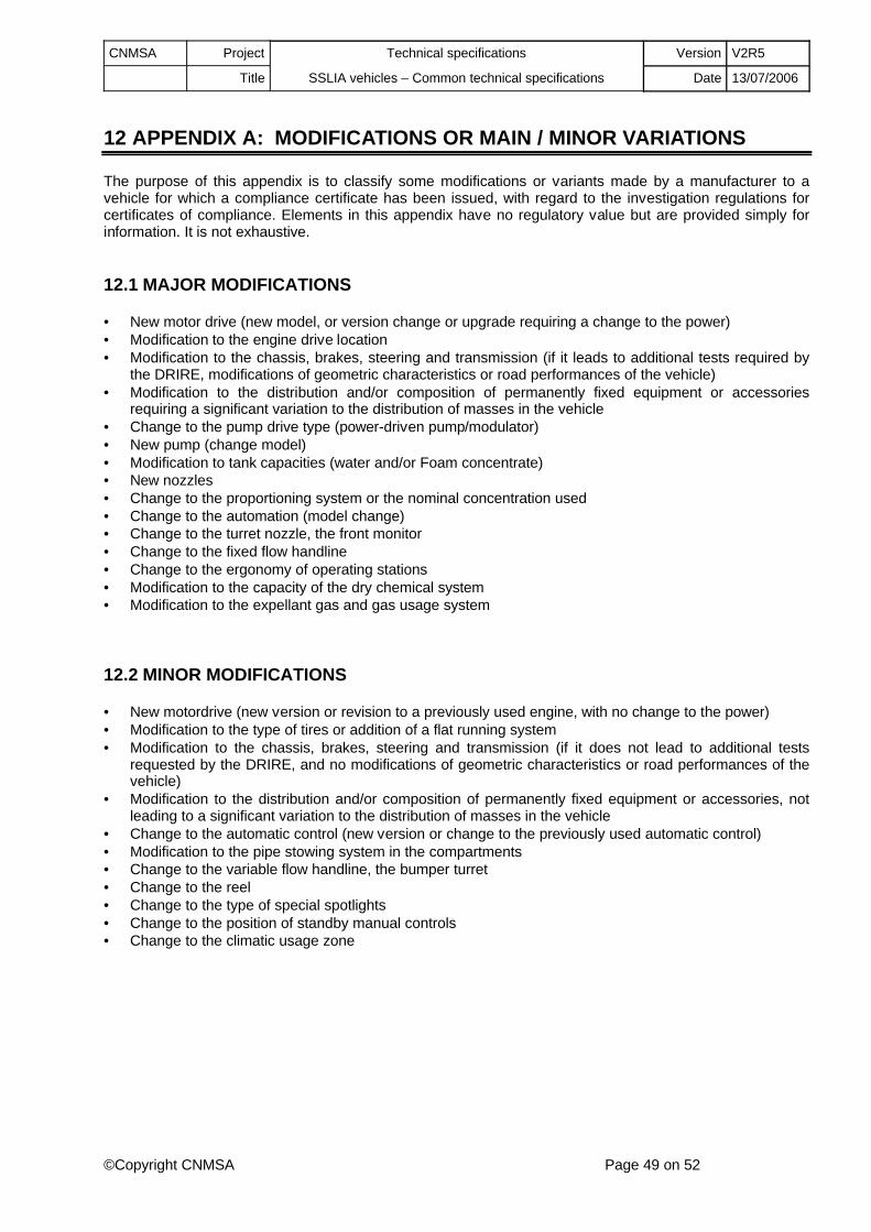
CNMSA Project Technical specifications Version V2R5
Title SSLIA vehicles – Common technical specifications Date 13/07/2006
©Copyright CNMSA Page 49 on 52
12 APPENDIX A: MODIFICATIONS OR MAIN / MINOR VARIATIONS
The purpose of this appendix is to classify some modifications or variants made by a manufacturer to a vehicle for which a compliance certificate has been issued, with regard to the investigation regulations for certificates of compliance. Elements in this appendix have no regulatory value but are provided simply for information. It is not exhaustive.
12.1 MAJOR MODIFICATIONS
• New motor drive (new model, or version change or upgrade requiring a change to the power)• Modification to the engine drive location • Modification to the chassis, brakes, steering and transmission (if it leads to additional tests required by
the DRIRE, modifications of geometric characteristics or road performances of the vehicle)• Modification to the distribution and/or composition of permanently fixed equipment or accessories
requiring a significant variation to the distribution of masses in the vehicle • Change to the pump drive type (power-driven pump/modulator)• New pump (change model)• Modification to tank capacities (water and/or Foam concentrate)• New nozzles• Change to the proportioning system or the nominal concentration used• Change to the automation (model change)• Change to the turret nozzle, the front monitor• Change to the fixed flow handline• Change to the ergonomy of operating stations• Modification to the capacity of the dry chemical system• Modification to the expellant gas and gas usage system
12.2 MINOR MODIFICATIONS
• New motordrive (new version or revision to a previously used engine, with no change to the power)• Modification to the type of tires or addition of a flat running system• Modification to the chassis, brakes, steering and transmission (if it does not lead to additional tests
requested by the DRIRE, and no modifications of geometric characteristics or road performances of the vehicle)
• Modification to the distribution and/or composition of permanently fixed equipment or accessories, not leading to a significant variation to the distribution of masses in the vehicle
• Change to the automatic control (new version or change to the previously used automatic control)• Modification to the pipe stowing system in the compartments• Change to the variable flow handline, the bumper turret• Change to the reel• Change to the type of special spotlights• Change to the position of standby manual controls• Change to the climatic usage zone

CNMSA Project Technical specifications Version V2R5
Title SSLIA vehicles – Common technical specifications Date 13/07/2006
©Copyright CNMSA Page 50 on 52
13 APPENDIX B: BUYERS GUIDE
The purpose of this appendix is to guide future buyers by informing them about the elements that might need to be clarified and negotiated at the time that a contract for the purchase of an ARFFS fire fighting vehicle is concluded, for each point in the technical specifications. In this respect, the elements given in this appendix have no regulatory value but are simply given for information.
Chapter 2.3: The buyer must specify the climatic zone in which the fire engine will be used. The buyer may also specify the normal relative humidity, particularly for hot zones. Finally, the manufacturer must be informed about any use of the vehicle with different water (brackish water, sea water, etc.).
Chapter 2.4: The estimated life, maintenance conditions and the anti-corrosion protection level shall be agreed upon between the manufacturer and the buyer.
Chapter 2.6: Road performances defined by these specifications are supposed to be satisfactory for all aerodromes. However in special cases, the buyer may need to specify higher road performances in order to respect response times fixed by the regulations in force.
Chapter 2.9: The buyer's attention is drawn to road usage restrictions due to outsize vehicles. Therefore, if the buyer wishes to remain within these limits, he should specify this in his specification. Conversely, it is impossible to design a vehicle containing more than 9500 l of usable water capacity, while remaining within these limits.
Chapter 3.1: If the vehicle might be used at altitudes greater than 600 meters (in ZA or ZVA – Public Airport zone or Public Airport Influence Zone), the buyer should inform the manufacturer so that the manufacturer can adapt the drive system to guarantee the same road and/or hydraulic performances at the given altitude.
Chapter 3.5: The buyer shall indicate if it is necessary to make an air connection to the outside and to specify the location (for example rear left of the vehicle). The buyer shall order the outside part of the fitting with the vehicle. The decelerator action mode should be agreed upon between the buyer and the manufacturer.
Chapter 3.7: For some chassis, the buyer may request a central greasing system.
Chapter 3.8: For some chassis, the buyer may request installation of systems so that vehicles can run flat after a burst tire.
Chapter Erreur ! Source du renvoi introuvable.: For vehicles with a total gross weight of less than 3.5 Tonnes, the buyer may request installation of a standard traction coupling or a winch so that these vehicles can pull themselves out if they get stuck. However, these systems shall be installed respecting the chassis geometric characteristics defined in chapter 2.4.
Chapter 3.12: The definition of additional supplies not included in the standard onboard batch (spare wheel, tooling, diagnostic or nozzles, etc.) shall be agreed upon between the buyer and the manufacturer.
Chapter 4.2.1: The buyer shall specify the number of seats and self-contained breathing apparatuses to be provided if there are more than two seats (in particular, for vehicles with a usable water capacity greater than 4500 liters, he should specify if self-contained breathing apparatuses are to be fitted on the additional seats). The buyer and manufacturer should work together to reach a common agreement about the system for presentation of the self-contained breathing apparatuses - seat, bench, sliding drawer, etc. The vehicle buyer may request installation of a «windshield deluge system» for windows cleaning by discharging water, and air conditioning in the cab. The vehicle buyer can consider the expediency of a so-called « club » cab on vehicles with a usable water capacity less than or equal to 4500 liters. The buyer and the manufacturer should work together to determine the quantity and type of radiophone equipment to be installed.
Chapter : The buyer should specify the type of internal seats for passengers, if any.
CNMSA Project Technical specifications Version V2R5
Title SSLIA vehicles – Common technical specifications Date 13/07/2006
©Copyright CNMSA Page 51 on 52
Chapter 4.3.1: A buyer who would like a greater carrying capacity should specify the capacity and provide the manufacturer with a list of additional accessories and/or equipment. The buyer should specify the list of accessories to be supplied by the manufacturer. The buyer and the supplier should come to an agreement particularly about the supply of pressurized equipment (self-contained breathing apparatus, O² cylinder, extinguisher, etc.).
Chapter Erreur ! Source du renvoi introuvable.: The compartment layout drawing should be agreed upon between the buyer and the manufacturer. The buyer may examine the expediency of requesting additional compartments. The compartment closing system (curtains, swinging doors, sliding doors) shall be agreed upon between the buyer and the supplier.
Chapter 4.4.1: The buyer should specify the locations, dimensions and value of the alphanumeric identification character(s). The buyer may also request a customized registration, depending on the aerodrome on which the vehicle will be used.
Chapter 5.1.3: The buyer shall specify the location, if it is not at the rear left of the vehicle. The buyer should order the external part of the plug with the vehicle.
Chapter 5.2.1: The buyer can install additional radiophone equipment in addition to the basic aeronautical radiophone equipment, for example portable radiophones on charger in cab.
Chapter 5.3.2: The type of marking lights (rotating lights, light strips, penetration lights, etc.) shall be agreed upon between the buyer and the manufacturer.
Chapter 5.3.3: For vehicles with a total gross weight of more than 3.5 Tonnes, the buyer should specify the type of special spotlights requested and the associated power supply type (peripheral lighting or telescopic mast).
Chapter 5.3.6: The detail of devices necessary for arctic zones shall be agreed upon between the buyer and the manufacturer.
Chapter 6.1: Materials used for manufacturing of elements of the hydraulic circuit shall be agreed upon between the buyer and the user, particularly when particular operating conditions (for example brackish water) require specific materials (316 L stainless steel in the previous example). The buyer shall examine the expediency of having an automatic draining system installed.
Chapter 6.4: the buyer shall specify the solution that he wants to use for high pressure supply orifices: non-return valve or other valve.
Chapter 6.5: The buyer should ask the manufacturer to provide all usable information about the protection process or product used, and particularly the application method, the frequency of checks and systematic intervals between reconditioning. He may ask for an automatic and progressive closing system for the pressurized supply connector valve when the water tank is full. The buyer shall specify the minimum usablewater capacity for foam production.
Chapter 6.7: The buyer should indicate the nominal concentration of foam concentrates that he uses.
Chapter 6.8: On some vehicles, the manufacturer shall propose an automatic system for returning the turret to the « Drive » position, with automatic locking if necessary.
Chapter 6.9: The customer and the manufacturer should reach an agreement about the method of storing hoses in compartments (rolled, wound, flat-bed, horizontal or vertical drawer, etc.). The buyer shall specify the installation side of the nozzle on the reel.

CNMSA Project Technical specifications Version V2R5
Title SSLIA vehicles – Common technical specifications Date 13/07/2006
©Copyright CNMSA Page 52 on 52
Chapter Erreur ! Source du renvoi introuvable.: The buyer of a vehicle with a usable capacity of more than 4500 liters should specify if he would like a bumper turret to be installed, and the required flow.
Chapter 6.11: The buyer of a vehicle with a usable capacity of more than 4500 liters should specify if he would like to install a front monitor on an articulated boom, and the required flow.
Chapter 7.1: The buyer should inform the manufacturer about the density of the dry dry chemical that he uses, and the expellant gas that he wants to use (nitrogen or CO2). He should also mention if he would like to purchase spare cylinders for the expellant gas at the same time as the vehicle. He should indicate the capacity that he would like for the dry dry chemical tank if it is greater than 250 kg. Finally, he can examine the expediency of acquiring closing elements necessary for a repeat hydraulic test for tanks subject to regulation for pressure vessels, at the same time as he purchases the vehicle. The buyer should inform themanufacturer about the maximum anteriority that he accepts on the pressure vessel test date at the time of delivery.
Chapter 7.3: The buyer should specify the location of the dry chemical tank pressurization control on foam and dry chemical vehicles.
Chapter 7.4: The buyer should inform the manufacturer if the vehicle might be used at altitudes of more than 600 meters (in ZA or ZVA), so that the manufacturer can adapt the dry chemical system to guarantee the same performances to the buyer at the given altitude.
Chapter 7.5: In order to reduce costs of training on the use of a dry chemical system, the buyer may ask the manufacturer to adapt the dry chemical system so that he can use compressed air as an propellant gas during training periods. In this case, he will need to acquire the complementary elements (cylinders, couplings, etc.) at the same time as the vehicle.
Chapter 7.6: The method of storing hoses in the compartments (rolled, wound, flat-bed, horizontal or vertical drawer, etc.) shall be agreed upon between the customer and the manufacturer. The buyer may consider whether or not it is expedient to install a reel according to chapter 6.13 to replace flat hoses.
Chapter 7.7: The buyer shall acquire the mobile part of the blowing coupling.
Chapter 8.1: The buyer and the manufacturer shall come to an agreement about the cab layout drawing and the arrangement of controls. The buyer may consider whether or not it is expedient to provide a reversing camera for use by the driver.
Chapter 8.1.2: The buyer shall specify his preferences about whether or not automatic controls should be kept, if this choice is possible. He may examine the expediency of moving the control and the outside intake indicator towards the maneuvering station on the ground. He may also ask for displacement of full flow / half-flow and solid stream / spray stream controls onto the instrument panel.
Chapter 8.6: The buyer should specify the consequences of interrupting the rinsing cycle (return to start, restart at the point at which it was interrupted, etc.).
Chapter 8.9: The buyer and the manufacturer should come to an agreement about the composition and nature of additional documents (maintenance instructions, illustrated parts lists; etc.) or computer versions of documents.
Chapters 9 and 10: The buyer and the manufacturer should come to an agreement about the checks and tests performed by the buyer during the vehicle acceptance. The buyer of a vehicle on which road tests are carried out should examine whether or not it is expedient to request the installation of new tires after the tests have been carried out.