ARCHITECTURAL WIRE ROPE RAILING - …railco.wcwr.com/RAIL-CO Architectural Railing Catalog...
40
ARCHITECTURAL WIRE ROPE RAILING
Transcript of ARCHITECTURAL WIRE ROPE RAILING - …railco.wcwr.com/RAIL-CO Architectural Railing Catalog...

ARCHITECTURALWIRE ROPE RAILING

Clean. Sturdy. Restrained.
A custom architectural railing system like the ones found in this catalog stand on their own as a safe, durable, and unique choice in both residential and commercial applications. In a residential setting, the low profile nature of a stainless steel wire rope railing provides a virtually unobstructed view; removing the boundary between your deck and a relaxing sunset. In a public setting, the railing system ensures a safe environment while not detracting from the surrounding design or architectural elements.
Hardware solutions found in this catalog were developed for and taken directly from marine applications. These fittings and wire rope line are made from Type 316 stainless steel and have been time-tested in a rough saltwater environment. You can be confident that a stainless steel architectural railing system from RAIL-CO will stand up to any type of weather while maintaining its unique and elegant appearance for years to come.
RAIL-CO is part of West Coast Wire Rope & Rigging, Inc., a family-owned business that has been fabricating cable railing systems for nearly 60 years. We are uniquely qualified to work directly with engineers, architects, contractors, and property owners. We are happy to work with you in order to come up a system that fits with your specific project needs/desires. We can provide both completed systems as well as individual components.

01
Introduction to Architectural Railing
Deck Toggle
Termination Stud
Threaded Bolt
Threaded Stud System
Threaded Eye
Threaded Termination Stud
Accessories
Frequently Asked Questions
Terms and Conditions
Round Head
Countersunk Termination Stud
Trellis Hardware
Stud Tensioning Internal Adjuster
Invisiware®
Toggle Jaw
Railing Planning Worksheet
PAGE 04
PAGE 14
PAGE 29
PAGE 06
PAGE 03
PAGE 16
PAGE 30
PAGE 08
PAGE 24
PAGE 18
PAGE 35
PAGE 10
PAGE 26
PAGE 20
PAGE 12
PAGE 28
PAGE 22
TABLE O
F CO
NTEN
TS
www.RAIL-CO.net

02
photo by Aaron Fiedler

www.RAIL-CO.net03
TERM
S AN
D C
ON
DITIO
NS
REQUEST FOR QUOTATION, PLACEMENT, OR ACCEPTANCE OF ORDERA request for quotation, placement, or acceptance of an order by Buyer shall constitute an acceptance of the Terms and Conditions contained herein. Any of the Buyer’s Terms and Conditions which are in addition to, or different from, those contained herein, which are not separately agreed to by Seller in writing, and hereby objected to and shall be of no effect. All offers shall be deemed accepted by buyer upon transmission to Seller of Buyer’s acceptance of the offer in any reasonable manner.
TAXESApplicable state Sales and/or Use Tax will be added unless Seller has a signed Sales Tax Exempt certificate on file. Taxes are not included in quoted price.
PRICEPublished prices and quoted prices, unless otherwise specified, are subject to change without notice. Seller reserves the right to revise the pricing if there is any change in quantity, inventory availability, size, finish, or method of shipment different from those contained in the original order.
INSPECTIONBuyer shall promptly inspect goods upon receipt and notify Seller of any defect in workmanship, transit damage, or otherwise not in conformity with the requirements of the order. Seller, at its option, may correct or have corrected the nonconformity. Seller will cooperate with Buyer in filing claims with freight carriers. All claims for shortages, shipping, or clerical errors shall be made in writing no later than ten (10) days after Buyer’s receipt of the products.
RETURNSNo product may be returned without the Seller’s consent or knowledge. Seller shall furnish instructions regarding disposition or rejected products. All returned merchandise is subject to inspection. The Seller reserves the right to impose a 20% restocking charge. Payment for all in-bound and out-bound freight charges will be the responsibility of the Buyer unless prior arrangements have been made. Seller will not accept the return of merchandise purchased over 90 days based on the original invoice date. Cut lengths of wire rope are not subject to return except upon written consent of the Seller. Any use of the goods by Buyer, or any failure to make a claim within the applicable time periods shall automatically constitute an irrevocable acceptance of the goods and an admission that the goods fully complied with the terms and conditions of the sale. A claim that product is non-conforming shall not entitle Buyer to deduct any sum from any invoice unless such claim has been allowed in writing by Seller.
PAYMENT TERMSTerms of payment shall be set forth on the face of the quotation or invoice. Terms are figured from the date of invoice. All payments are to be made in U.S. Dollars. Any unpaid balance after the required payment date shall be subject to a finance charge of 1-12% (18% per annum) per month from such date. Payments shall be made without right of setoff. Title of goods shall not pass to the Buyer until the entire purchase price and all other obligations of the Buyer under these terms of sale are paid performed in full. Seller shall have the right to suspend credit or to modify credit terms, or to withhold deliveries, when the Buyer’s financial condition so warrants. In the event the Seller is required to institute any type of action or proceeding to recover any obligations due Seller by Buyer, Seller shall be entitled to receive, as an additional item of damages, reasonable collection and/or attorney fees incurred by Seller in pursuit of Buyer.
SHIPMENTAll material shall be properly packed for shipment. The Seller shall comply with the Buyer’s routing and written shipping instructions. If such instructions are not previously received, Seller reserves the right to select carrier and routing. All shipments are F.O.B. Origin, unless other arrangements have been made.
DELIVERYAll goods quoted upon are subject to prior sales. In no event will the Seller be responsible for loss or damages due to failure to make delivery in accordance to the delivery estimate. In addition, the Seller shall not be liable for failure in shipment or delivery caused by fires, strikes, casualties, delays in transportation, acts of God, or other causes beyond the Seller’s control. Seller’s judgments shall be final and shall not subject Seller to any claim for damages by virtue of any shortages or failure to deliver.
TITLE-SECURITYFor security, title of goods shall not pass to the customer until the entire purchase price and all other obligations of the customer under these terms of sale are performed in full.
ARBITRATIONAll disputes that may arise between the parties regarding the interpretation of the contract and the legal effect of the contract shall, to the exclusion of any court of law, be arbitrated and determined in accordance with the latest Commercial Arbitration Rules of the American Arbitration Association. The arbitration proceeding shall be held in the city in that state where the principal office of the Seller is located. The parties recognize and consent to the above mentioned arbitration association’s jurisdiction over each and every one of them.
GOVERNING PROVISIONSThe parties hereto irrevocably submit to the venue and jurisdiction of the Federal and State courts sitting in Multnomah County, Oregon and waive claims as to inconvenient forum. In the event this agreement pertains to the sale of any goods outside the United States, the parties agree that the United Nations Convention for the International Sale of Goods shall not apply to this agreement.
WARRANTY AND LIMITATION OF REMEDIESExcept for the warranty that the product manufactured by Seller shall be made in a good and workmanlike manner and in accordance with the specifications therefore supplied or agreed to by Buyer, SELLER MAKES NO WARRANTY, EXPRESSED OR IMPLIED, AND ANY IMPLIED WARRANTY OR MERCHANTABILITY OR FITNESS FOR A PARTICULAR PURPOSE WHICH EXCEEDS THE FOREGOING WARRANTY IS HEREBY DISCLAIMED BY THE SELLER AND EXCLUDED FROM THIS AGREEMENT. The above warranty shall only apply during the first ninety (90) days following delivery of the Product to Buyer. Seller shall not be liable for any consequential or incidental damages, lost profits, punitive damages or losses or expenses of any kind. Buyer’s sole and exclusive remedy shall be the repair or replacement, at Sellers option, of product proven to be defective. Seller is hereby specifically granted the right to cure any proven or acknowledged defects. In any event, Seller’s maximum liability herein above shall not exceed the contract price for the Product proven to be defective. Notwithstanding anything to the contrary hereinabove, the limited warranties provided hereinabove shall not apply to any component parts or equipment not manufactured by the Seller, but purchased by Seller from other manufactures or are sold as is or assembled with Seller’s product. In those instances, all warranties are those made by the manufacturer and Seller herby disclaims any warranties, whether express or implied, INCLUDING ALL WARRANTIES OF MERCHANTABILITY AND FITNESS FOR A PARTICULAR PURPOSE. Seller’s limited warranty shall become null and void should Buyer attempt any repairs or alterations to the Product without Seller’s prior written consent. Seller’s limited warranty shall likewise not apply to any damage caused by misuse or neglect. Seller does not authorize any person, including its agents, employees, sales representatives, or distributors, to create, modify, expand, or extend any warranty or representation about the Product other than contained in the preceding sentences.

TOLL FREE–800.275.0482 04
INTR
OD
UCTI
ON
TO
RA
ILIN
G RAIL-CO’s position in the architectural railing industry is unique in that we have considerable experience in quoting, creating, and assembling wire rope systems for all types of clients/customers. We take pride in our ability to address the unique challenges and details that custom projects can contain.
We work with architects, home/property owners, and everyone else in between. If you are new to wire rope architectural railing, this catalog will provide you with the information you need to get you on your way to designing your new railing. If you are familiar with these railing systems, we haven’t forgotten about you. You will be happy to see that we’ve included a considerable amount of technical details and product options to ensure the project you are working on comes together as easily as possible.
Let’s begin, shall we?
Types of Wire Rope:
When it comes to architectural wire rope railings, two types (also called “constructions”) of rope are available through RAIL-CO; 1x19 and 7x7. If you are not familiar with wire rope, here is a quick lesson.
Wire rope is constructed by combining strands of wires. Individual wires are twisted into strands, and those strands are twisted into the final rope. A 1x19 rope contains one strand of 19 wires... A 7x7 rope contains seven strands, each made up of 7 wires.
7x7 rope is more flexible than 1x19 due to the smaller diameter of the individual wires. If your project is going to have any curve or angle to it, 7x7 might be a better option than 1x19. Since the two ropes are constructed differently, they are going to have a different aesthetic. Here is an example of each rope type to help you decide which is going to be best for your project.
Cable Assemblies:
A complete cable assembly must have the following elements– 1) A turnbuckle or adjustable threaded terminal to tension the cable. 2) An attachment point at each end, with an end fitting, that will support the tension of the cable.Without these two elements, you do not have a proper cable assembly...
Clearly, aesthetics are very important to your design. Knowing this, RAIL-CO has provided a number of different fittings that function the same way, but have different form factors. You can mix & match end fittings to achieve the exact assembly that you want.
Cable Set-up:
• Cable assemblies should be spaced 3.5 inches apart to meet the 4 inch code present in most areas.• End posts need to be strong enough to support the number of cable assemblies used and tensioned to 350 lbs. per cable assembly.• Intermediate posts need to be placed every 4 feet to prevent line deflection of more than 4”.• Cable lengths need to be kept under 50 feet for most railing systems in order to maintain proper tensioning. Exceptions can be made when utilizing a Swage-to-Swage Turnbuckle (pg. 32).
1x19
7x7

www.RAIL-CO.net05
INTR
OD
UCTIO
N TO
RA
ILING
Fitting Types:
CUT...
PULL...
CAP!
*To ensure your project meets code, always check your local building authority.
END POSTINTERMEDIATE POSTTURNBUCKLE/TENSIONER
RECOMMENDEDTENSIONING
ORDER3.5” (RECOMMENDED)*
12
3
4
579
68
NOT MORE THAN 4’*
PUSH...
LOCKED!
Machine Swage (prounounced “swedj”) fittings are attached by using a cold forming press. The completed fitting has a smooth, uniform appearance. Swaging services can be performed by your nearest RAIL-CO shop, or you can rent a swaging machine and do it yourself on-site.
•
Crimp fittings are attached to the wire rope by a simple hand tool. Crimp fittings will only provide 60-70% of the wire rope’s strength. This loss in system strength must be accounted for in the design stage of your project. Crimp fittings are only available for 1/8” and 3/16” wire rope. A crimping tool is available to borrow from RAIL-CO at no extra charge when you purchase your hardware from us.
•
Mechanical fittings are generally more expensive than the Swage or Crimp fittings, but their main advantage is that they do not require any special tools for installation. If your project is on the smaller side, the extra cost of the mechanical fittings can be offset by the speed and ease of installation.
•
Push-to-Lock fittings are only available for 1x19LH wire rope. Simply insert the wire rope end into a fitting on one side of your run and install a tensioner on the other end, then tension the line. A cable release tool is available for order (pg. 33).Please note, this tool will only work on fittings that have not yet been tensioned.
•
Pull-to Lock fittings are only available for 1x19LH wire rope and are also quite simple to install. Attach a tensioner on one end post, slip the end fitting into a pre-drilled hole in the other end post and pull the cable all the way through the end fitting. Tension the cable, then cut the excess cable off and press on the cap to cover the bare cable end. That’s it!
•
Basic Railing Framework: Cable runs less than 50 feet (from End Post to End Post) are recommended. If your application requires a run of more than 50 feet, Swage to Swage Turnbuckles (pg. 32) are required. Regardless of total cable run length, Intermediate Posts should be used every 4 feet. Most codes stipulate that a 4” ball not be able to fit between two rails with a 25 pound load on one line. We recommend 3.5” rail spacing to ensure your project meets this requirement.*
•

TOLL FREE–800.275.0482 06
FREQ
UEN
TLY
ASK
ED Q
UES
TIO
NS
A machine swage fitting is attached to the wire rope by a cold forming process fixing the fitting directly to the rope. A swage fitting should not be confused with Hand Crimp fittings or Mechanical fittings. Swaged fittings, when properly assembled, maintain the full rope strength. Swage fittings can NOT be attached to a cable by any means other than a swageing machine.
What is a Machine Swage Fitting?
Hand crimp fittings are designed to be fixed to the wire rope by using a special crimping tool. These fittings are popular due to their ease of installation, but that ease comes with reduced strength that needs to be compensated for during the planning stage.
What is a Hand Crimp Fitting?
Generally, 1x19 cable should be used for all railing applications. 1x19 cable is stiff and low-stretch, perfect for railings with runs up to 50 feet. 7x7 cable is more flexible with more stretch and can be used for railings with very short runs. 7x19 cable is very flexible but the smaller wires make it less durable.
What Type of Wire Rope Should I Use?
All materials sold by RAIL-CO are made out of Type 316 stainless steel.What Grade of Stainless Steel is Used in Fittings Sold by RAIL-CO?
3/16” wire rope is the most popular size and good for most railing applications. In high traffic applications such as airports, stadiums, or amusement parks, 1/4” rope is highly recommended. For residential applications where view and unobtrusiveness are paramount, 1/8” rope works well.
What Size Wire Rope Do I Use?
No. RAIL-CO does not carry steel or galvanized fittings for commercial or residential line systems. We believe that these materials simply are not able to hold up to the elements like stainless steel does.
Are Steel or Galvanized Fittings Available from RAIL-CO?
While we can’t know all of the questions you might have regarding your future project, we’ve worked on a lot of projects that are probably similar. We have developed a good feel for some of the questions you most likely have right about now.
We’ve put together the following FAQ section with the hope that the information found in this catalog helps move your process forward rather than just creates more questions. If there is a detail that remains unclear or you still have a question or two after reading through the FAQs, please feel free to shoot us an e-mail or give us a call. Who knows, you just might help us add a question or two to future versions of this catalog!
1x19 7x7
A mechanical fitting is attached to the wire rope by the fitting compressing the cable with a cone inside the fitting and/or the cable. Mechanical fittings are assembled to the cable with simple hand tools. Mechanical fittings are larger in diameter than Swage or Hand Crimp fittings and can be reused after replacing an internal piece, but carry a hefty price tag.
What is a Mechanical Fitting?
7x19
Generally, aluminum is too soft for wire rope railings. There is also the possibility of aluminum and stainless steel reacting where moisture is present and causing electrolysis (corrosion).
Can I Make my Framework Out of Aluminum?

www.RAIL-CO.net07
FREQ
UEN
TLY A
SKED
QU
ESTION
S
Swageless fittings are installed onto the wire rope by hand at the job site and do not require special equipment. Since the fittings can be installed onto the ends of the rope at the job site, the intermediate holes (holes in the supporting railing posts) only need to be large enough for the rope to pass through. Swageless fittings are generally more costly than fittings that are swaged. However, on smaller projects, the ease of using swageless fittings may be worth it to you. Swageless fittings are offered for use with 1x19 constructed 1/8” and 3/16” diameter rope.
What is a Swageless Fitting?
For architectural railing purposes, wire rope needs to be tensioned mechanically. The most common way to do this is with a turnbuckle. Generally, a conventional turnbuckle can tension up to 50 feet of line in a straight run and still meet code. Runs longer than 50 feet can be accomplished by using the Swage to Swage Turnbuckle (Pg. 32).
How Long can I Run a Single Piece of Wire Rope?
Yes. Cable works great for railing but only if you have the ability to tighten it with a turnbuckle or with a through-bolted threaded terminal. Even if you had some way of pre-tensioning the rope and attaching it without a turnbuckle or threaded terminal, the rope would eventually stretch through people leaning against it, children climbing, the building settling, etc. You want the ability to go back at a later date and tighten everything up.
Do I Need a Tensioner in my Cable Assembly?
A turnbuckle is a metal coupling device consisting of right- and left-hand threaded members screwed into an internally threaded body which when rotated, expands or contracts.
What is a Turnbuckle?
The manufacturers of our products recommend 350 lbs. of tension on each rope assembly for a cable railing.How Much Tension Do I Need?
No. A true 90° corner will damage the wire rope no matter what construction of cable is used. The physics of rope does not allow the tension to be equally transmitted from one side of a corner to another side. Tension has to be maintained throughout the entire length of the cable run to meet code. An end fitting should be used to make the corner transition and keep the cable tension in a straight line.
Can a Wire Rope Line go Around a 90° Corner?
Spacing, tension, and framework guidelines are strict to ensure your final product meets code and is safe. Wire rope railing is not a new business and these guidelines are time-tested standards.
Why are the Guidelines on Spacing, Tension, and Framework so Strict?
When the fitting is held vertically, threads slope up and to the right for right-hand thread or up and to the left for left-hand thread.How Can I Tell Right-hand Thread from Left-hand Thread?
Pull-to-Lock type fittingPush-to-Lock type fitting
With a comprehensive order form completed, associates at any of our three RAIL-CO facilities can fabricate all the cable sections you might need. If you’re the adventureous type, RAIL-CO has all the tools and machines needed to let you fabricate your lines on site! If you’re interested, complemenetary 2-day equipment rental comes with every RAIL-CO order. If you need more time, equipment is available for $50/day afterwards.
Can I Swage My Cable Sections Myself or Do I Need to Have RAIL-CO Fabricate Them?

TOLL FREE–800.275.0482 08
Hands down the most cost effective cable attachment and tensioning solution offered by RAIL-CO is the Threaded Stud system. This system normally uses a Flat Washer (pg. 31) and a Hex Nut (pg. 33) for tensioning against the end verticals/posts in the run. An Acorn Nut is installed on the protruding threads to finish off the attachment and lock the tensioning nut in position.
THREA
DED
STU
D S
YST
EM
1x19 7x7 7x19

www.RAIL-CO.net09
SWAGE FITTING
Threaded Stud
CRIMP FITTING
THREA
DED
STUD
SYSTEM
SWAGE FITTING
Threaded Stud with Wrench Flat
Thread Size Wire Size Thread Length Part Number
1/4–28 UNF LH 3/16” 2–1/4” 14LL316FLH
1/4–28 UNF 3/16” 2–1/4” 14LL316FRH
5/16–24 UNF LH 3/16” 2–3/8” 516LL316FLH
5/16–24 UNF 3/16” 2–3/8” 516LL316FRH
5/16–24 UNF LH 1/4” 2–3/8” 516LL14FLH
5/16–24 UNF 1/4” 2–3/8” 516LL14FRH
3/8–24 UNF LH 1/4” 2–3/4” 38LL14FLH
3/8–24 UNF 1/4” 2–3/4” 38LL14FRH
Thread Size Wire Size Thread Length Part Number
10–32 UNF 1/8” 3/8” 10TJLL18S
10–32 UNF 1/8” 1–3/4” 10LL18RH
1/4–28 UNF 1/8” 7/16” 14TJLL18S
1/4–28 UNF 1/8” 1–1/2” 14LLP18RH
1/4–28 UNF 1/8” 2–1/4” 14LL18RH
1/4–28 UNF 1/8” 3–1/4” 14ASLL18RH
1/4–28 UNF 3/16” 7/16” 14TJLL316S
1/4–28 UNF 3/16” 1–1/2” 14LLP316RH
1/4–28 UNF 3/16” 2–1/4” 14LL316RH
1/4–28 UNF 3/16” 3–1/4” 14ASLL532RH
5/16–24 UNF 3/16” 7/16” 516LLE316RH
5/16–24 UNF 3/16” 1–1/2” 516LLP316RH
5/16–24 UNF 3/16” 2–3/8” 516LL316RH
5/16–24 UNF 1/4” 7/16” 516TJLL14S
5/16–24 UNF 1/4” 1–1/2” 516LLP14RH
5/16–24 UNF 1/4” 2–3/8” 516LL14RH
3/8–24 UNF 1/4” 7/16” 38TJLL14S
3/8–24 UNF 1/4” 1–1/2” 38LLP14RH
3/8–24 UNF 1/4” 2–3/4” 38LL14RH
Thread Size Wire Size Thread Length Part Number
1/4–28 UNF 1/8” 7/16” 14CLLE18RH
1/4–28 UNF 1/8” 1–1/2” 14CLLP18RH
1/4–28 UNF 1/8” 2–1/4” 14CLL18RH
1/4–28 UNF 3/16” 7/16” 14TJCLL316S
1/4–28 UNF 3/16” 1–1/2” 14CLLP316RH
1/4–28 UNF 3/16” 2–1/4” 14CLL316RH
5/16–24 UNF 3/16” 7/16” 516CLLE316RH
5/16–24 UNF 3/16” 1–1/2” 516CLLP316RH
5/16–24 UNF 3/16” 2–3/8” 516CLL316RHMECHANICAL FITTING
Thread Size Wire Size Thread Length Part Number
1/4–28 UNF 1/8” 2–1/4” Left-hand–14HG18LH, Right-hand–14HG18RH
1/4–28 UNF 3/16” 2–1/4” Left-hand–14HG316LH, Right-hand–14HG316RH

TOLL FREE–800.275.0482 10
This simple and economical tensioning system provides for an extremely “clean” look concealing the adjusting threads internally. The typical application is for short to medium length cable runs in wire sizes ranging from 1/8” to 1/4”. Cable tensioning is easily accomplished with the use of an Allen wrench.
Additionally, the stud tensioners can be used in conjunction with other stud length combinations and systems to meet your design criteria.
STU
D T
ENSI
OIN
NG
IN
TERN
AL
AD
JUST
ER S
YST
EM

www.RAIL-CO.net11
Stud Tensioning Internal Adjuster
Thread Wire Size Closed Length Open Length Part Number Rec. Hole Size
1/4–28 UNF 1/8” 1.625” 2.375” ST06A18 21/64”
1/4–28 UNF 3/16” 1.750” 2.500” ST06A316 21/64”
5/16–24 UNF 3/16” 1.687” 2.437” STO8A316 25/64”
5/16–24 UNF 1/4” 1.750” 2.500” ST08A14 25/64”
SWAGE FITTING
Stud Tensioning Internal Adjuster - Assembly
Thread Wire Size Closed Length Open Length Part Number Rec. Hole Size
1/4–28 UNF 1/8” 1.975” 2.725” ST06A18C 21/64”
1/4–28 UNF 3/16” 1.812” 2.562” ST06A316C 21/64”
5/16–24 UNF 3/16” 1.875” 2.625” ST08316C 25/64”
CRIMP FITTING
Thread Cap Size Body Out. Dim. Body Length Total Length Part Number Rec. Hole Size
1/4–28 UNF 1/2” 5/16” 1.500” 1.625” ST06 21/64”
1/4–28 UNF 1/2” 5/16” 0.562” 0.687” ST06S 21/64”
5/16–24 UNF 9/16” 3/8” 1.500” 1.625” ST08 25/64”
5/16–24 UNF 9/16” 3/8” 0.562” 0.687” ST08S 25/64”
STUD
TENSIO
INN
G IN
TERN
AL A
DJU
STER SY
STEM
Thread Wire Size Length Part Number
1/4–28 UNF 1/8” 1.500” 14LLST18RH
1/4–28 UNF 3/16” 1.500” 14LLST316RH
5/16–24 UNF 3/16” 1.500” 516LLST316RH
5/16–24 UNF 1/4” 1.500” 516LLST14RH
SWAGE FITTING
Stud Tensioning Internal Adjuster Stud
Thread Wire Size Length Part Number
1/4–28 UNF 1/8” 1.500” 14CLLST18RH
1/4–28 UNF 3/16” 1.500” 14CLLST316RH
5/16–24 UNF 3/16” 1.500” 516CLLST316RH
CRIMP FITTING
Thread Wire Size Length Part Number
1/4–28 UNF 1/8” 1–5/8” 14HGST18RH
5/16–24 UNF 3/16” 1–5/8” 516HGST316RH
MECHANICAL FITTING
Thread Wire Size Closed Length Open Length Part Number Rec. Hole Size
1/4–28 UNF 1/8” 2–1/8” 3” ST06A18-HG 21/64”
5/16–24 UNF 3/16” 2–1/8” 3” ST08A316-HG 25/64”
MECHANICAL FITTING
1x19 7x7 7x19
1x19 7x7 7x19

TOLL FREE–800.275.0482 12
This cost effective cable tensioning system utilizes high quality closed turnbuckle assemblies and surface mount Termination Studs. Installation is made easy by simply drilling holes in your verticals for the cable to pass through. Tensioning is accomplished by the Termination Stud cap pulling against the end verticals/posts in the run. This system supports any type or style of post available for wire sizes of 1/8”, 3/16”, and 1/4”. Standard Termination Stud end fittings listed are for 2”, 4”, and 6” thick post configurations; however, Termination Studs are available for up to 12” thick post configurations (ask for pricing).
(In addition to new projects, this system has proven a popular choice for retrofitting existing rails to meet current codes.)TE
RM
INA
TIO
N S
TUD
SY
STEM

www.RAIL-CO.net13
Thread Wire Size Body Length Closed Length Open Length Rod Length Part Number
1/4–28 UNF 1/8” 4–1/4” 6–1/4” 9–1/4” 1–1/4” 14TTLL18TS1
1/4–28 UNF 1/8” 4–1/4” 7–1/8” 10–1/4” 2–1/4” 14TTLL18TS
1/4–28 UNF 1/8” 4–1/4” 9–1/8” 12–1/4” 4–1/4” 14TTLL18TS4
1/4–28 UNF 1/8” 4–1/4” 14–1/4” 11–1/8” 6–1/4” 14TTLL18TS6
1/4–28 UNF 3/16” 4–1/4” 6–1/2” 9–1/2” 1–1/4” 14TTLL316TS1
1/4–28 UNF 3/16” 4–1/4” 7–1/2” 10–1/2” 2–1/4” 14TTLL316TS
1/4–28 UNF 3/16” 4–1/4” 9–1/2” 12–1/2” 4–1/4” 14TTLL316TS4
1/4–28 UNF 3/16” 4–1/4” 11–1/2” 14–1/2” 6–1/4” 14TTLL316TS6
5/16–24 UNF 3/16” 4–3/4” 8” 10–3/4” 2–1/4” 516TTLL316TS
5/16–24 UNF 1/4” 4–3/4” 8–1/8” 10–3/4” 2–1/4” 516TTLL14TS
SWAGE FITTING
Thread Wire Size Body Length Closed Length Open Length Rod Length Part Number
1/4–28 UNF 1/8” 4 1/4” 6–1/4” 9–1/4” 1–1/4” 14TTCLL18TS1
1/4–28 UNF 1/8” 4 1/4” 7–1/8” 10–1/4” 2–1/4” 14TTCLL18TS
1/4–28 UNF 1/8” 4 1/4” 9–1/8” 12–1/4” 4–1/4” 14TTCLL18TS4
1/4–28 UNF 1/8” 4 1/4” 11–1/8” 14–1/4” 6–1/4” 14TTCLL18TS6
1/4–28 UNF 3/16” 4 1/4” 6–1/2” 9–1/2” 1–1/4” 14TTCLL316TS1
1/4–28 UNF 3/16” 4 1/4” 7–1/2” 10–1/2” 2–1/4” 14TTCLL316TS
1/4–28 UNF 3/16” 4 1/4” 9–1/2” 12–1/2” 4–1/4” 14TTCLL316TS4
1/4–28 UNF 3/16” 4 1/4” 11–1/2” 14–1/2” 6–1/4” 14TTCLL316TS6
CRIMP FITTING
Wire Size Cap Size Cap Thick. Body Out. Dim.* Body Length Part Number Rec. Hole Size
1/8” 1/2” .205” .250” 1.50” TSLL18 1/4”
3/16” 9/16” .205” .359” 1.75” TSLL316 3/8”
1/4” 9/16” .220” .427” 2.30” TSLL14 7/16”
SWAGE FITTING
Termination Stud
CRIMP FITTING
TERM
INA
TION
STUD
SYSTEM
Wire Size Cap Size Cap Thick. Body Out. Dim.* Body Length Part Number Rec. Hole Size
1/8” 1/2” .205” .210” 2.00” TS3C 7/32”
1/8” 9/16” .205” .292” 2.187” TS5C 5/16”
*before swage
MECHANICAL FITTING
Wire Size Cap Size Cap Thick. Body Out. Dim.* Body Length Part Number Rec. Hole Size
1/8” 9/16” 1/8” 0.375” 1–1/4” TSHG18 13/32”
3/16” 5/8” 1/8” 0.436” 1–1/4” TSHG316 7/16”
Thread Wire Size Body Length Closed Length Open Length Rod Length Part Number
1/4–28 UNF 1/8” 4–1/4” 7” 9–1/4” 1–1/4” 14TTHG18TS1
1/4–28 UNF 1/8” 4–1/4” 8” 10–1/4” 2–1/4” 14TTHG18TS
1/4–28 UNF 1/8” 4–1/4” 10” 12–1/4” 2–1/4” 14TTHG18TS4
1/4–28 UNF 1/8” 4–1/4” 12” 14–1/4” 2–1/4” 14TTHG18TS6
1/4–28 UNF 1/8” 4–1/4” 7” 9–1/4” 1–1/4” 14TTHG316TS1
1/4–28 UNF 1/8” 4–1/4” 8” 10–1/4” 2–1/4” 14TTHG316TS
1/4–28 UNF 1/8” 4–1/4” 10” 12–1/4” 2–1/4” 14TTHG316TS4
1/4–28 UNF 1/8” 4–1/4” 12” 14–1/4” 2–1/4” 14TTHG316TS6
MECHANICAL FITTING
Termination Stud Turnbuckle
1x19
7x7 7x19
1x19 7x7
7x19

TOLL FREE–800.275.0482 14
The Countersunk Termination Stud system has similar features to the Termination Stud system, except the end fittings are sunk into the end verticals in the run for a flush look. This system supports flat bar or tube style posts in wire sizes ranging from 1/8” to 3/16”. Countersunk Termination Stud end fittings listed are for 2”, 4”, or 6” thick post configurations.
Installation is simple. When you use a standard 82° countersink on your end verticals/posts, the fitting will insert flush with the face.
CO
UN
TERSU
NK
TER
MIN
ATI
ON
STU
D S
YST
EM

www.RAIL-CO.net15
Countersunk Termination Stud Thread-on Cap
Thread Wire Size Body Length Closed Length Open Length Cap Size Part Number Rec. Hole Size
1/4–28 UNF 1/8” 4–1/4” 8–1/4” 10–5/8” 9/16” 14TTLL18CTS 23/64”
1/4–28 UNF 1/8” 4–1/4” 10–1/4” 12–5/8” 9/16” 14TTLL18CTS4 23/64”
1/4–28 UNF 1/8” 4–1/4” 12–1/4” 14–5/8” 9/16” 14TTLL18CTS6 23/64”
1/4–28 UNF 3/16” 4–1/4” 8–3/8” 11–1/8” 9/16” 14TTLL316CTS 23/64”
1/4–28 UNF 3/16” 4–1/4” 10–3/8” 13–1/8” 9/16” 14TTLL316CTS4 23/64”
1/4–28 UNF 3/16” 4–1/4” 12–3/8” 15–1/8” 9/16” 14TTLL316CTS6 23/64”
SWAGE FITTING
Countersunk Termination Stud Turnbuckle
Thread Wire Size Body Length Closed Length Open Length Cap Size Part Number Rec. Hole Size
1/4–28 UNF 1/8” 4–1/4” 8–3/8” 11–1/4” 9/16” 14TTCLL18CTS 23/64”
1/4–28 UNF 1/8” 4–1/4” 10–3/8” 13–1/4” 9/16” 14TTCLL18CTS4 23/64”
1/4–28 UNF 1/8” 4–1/4” 12–3/8” 15–1/4” 9/16” 14TTCLL18CTS6 23/64”
1/4–28 UNF 3/16” 4–1/4” 8–1/4” 11” 9/16” 14TTCLL316CTS 23/64”
1/4–28 UNF 3/16” 4–1/4” 10–1/4” 13” 9/16” 14TTCLL316CTS4 23/64”
1/4–28 UNF 3/16” 4–1/4” 12–1/4” 15” 9/16” 14TTCLL316CTS6 23/64”
CRIMP FITTING
Thread Body Length Body Out. Dim. Cap Angle Cap Size Part Number Rec. Hole Size
1/4–28 UNF 9/16” 0.359” 82° 9/16” CTST14 23/64”
CO
UN
TERSU
NK
TERM
INA
TION
STUD
SYSTEMWire Size Cap Size Cap Angle Body Out. Dim. Body Length Part Number Rec. Hole Size
1/8” 1/2” 82° 0.250” 1.500” CTSLL18 17/64”
3/16” 9/16” 82° 0.359” 1.750” CTSLL316 21/64”
SWAGE FITTING
Countersunk Termination Stud
Thread Wire Size Cap Angle Body Out. Dim. Body Length Part Number Rec. Hole Size
1/8” 1/2” 82° 0.210” 2.625” CTSCLL18 15/64”
3/16” 6/16” 82° 0.292” 2.750” CTSCLL316 5/16”
CRIMP FITTING
1x19 7x7 7x19
1x19 7x7 7x19

TOLL FREE–800.275.0482 16
Designed for ease of installation in a confined space (within 4-1/2” of an obstruction such as an adjacent wall or post), this cable tensioning system utilizes closed turnbuckle assemblies and surface mount End Fitting hardware.
End Fitting options include Acorn Nuts (pg. 33), Hex Nuts (pg. 33), Dome Nuts (pg. 30), and Ball Ends (pg. 31). Installation is easy, just drill holes in your verticals for the wire rope to pass through. Tensioning is accomplished by the End Fitting pulling against the end verticals/posts in the run. This system supports any type or style of post and is available in 1/4”, 3/16”, and1/4” wire sizes. Standard Termination Stud end fittings listed are for 2”, 4” or 6” thick post configurations; but Termination Studs are also available for up to 12” thick post configurations (ask for more details).
THREA
DED
TER
MIN
ATI
ON
STU
D S
YST
EM

www.RAIL-CO.net17
Thread Wire Size Body Length Closed Length Open Length Part Number
1/4–28 UNF 1/8” 4–1/4” 7–5/8” 10–1/4” 14TTLL18S
1/4–28 UNF 1/8” 4–1/4” 9–5/8” 12–1/4” 14TTLL18S4
1/4–28 UNF 1/8” 4–1/4” 11–5/8” 14–1/4” 14TTLL18S6
1/4–28 UNF 3/16” 4–1/4” 7–3/4” 10–1/2” 14TTLL316S
1/4–28 UNF 3/16” 4–1/4” 9–3/4” 12–1/2” 14TTLL316S4
1/4–28 UNF 3/16” 4–1/4” 11–3/4” 14–1/2” 14TTLL316S6
5/16–24 UNF 3/16” 4–3/4” 8–5/8” 11–5/8” 516TTLL316S
5/16–24 UNF 1/4” 4–3/4” 8–1/2” 12” 516TTLL14S
SWAGE FITTING
Threaded Termination Stud Turnbuckle
Thread Wire Size Body Length Closed Length Open Length Part Number
1/4–28 UNF 1/8” 4–1/4” 7–15/16” 10–5/8” 14TTCLL18S
1/4–28 UNF 1/8” 4–1/4” 9–15/16” 12–5/8” 14TTCLL18S4
1/4–28 UNF 1/8” 4–1/4” 11–15/16” 14–5/8” 14TTCLL18S6
1/4–28 UNF 3/16” 4–1/4” 7–7/8” 10–1/2” 14TTCLL316S
1/4–28 UNF 3/16” 4–1/4” 9–7/8” 12–1/2” 14TTCLL316S4
1/4–28 UNF 3/16” 4–1/4” 11–7/8” 14–1/2” 14TTCLL316S6
Thread Wire Size Length Part Number
1/4–28 UNF 1/8” 3/4” 14TJLL18S
1/4–28 UNF 3/16” 15/16” 14TJLL316S
5/16–24 UNF 3/16” 15/16” 516TJLL316S
5/16–24 UNF 1/4” 1–1/8” 516TJLL14S
SWAGE FITTING
Threaded Termination Stud
Thread Wire Size Length Part Number
1/4–28 UNF 1/8” 15/16” 14TJCLL18S
1/4–28 UNF 3/16” 13/16” 14TJCLL316S
CRIMP FITTING
THREA
DED
TERM
INA
TION
STUD
SYSTEM
CRIMP FITTING
Thread Wire Size Length Part Number
1/4–28 UNF 1/8” 1–5/8” 14HGST18RH
5/16–24 UNF 3/16” 1–5/8” 516HGST316RH
MECHANICAL FITTING
Thread Wire Size Body Length Closed Length Open Length Part Number
1/4–28 UNF 1/8” 4–1/4” 8–1/8” 10–3/8” 14TTHG18S
1/4–28 UNF 1/8” 4–1/4” 10–1/8” 12–3/8” 14TTHG18S4
1/4–28 UNF 1/8” 4–1/4” 12–1/8” 14–3/8” 14TTHG18S6
1/4–28 UNF 3/16” 4–1/4” 8–1/8” 10–3/8” 14TTHG316S
1/4–28 UNF 3/16” 4–1/4” 10–1/8” 12–3/8” 14TTHG316S4
1/4–28 UNF 3/16” 4–1/4” 12–1/8” 14–3/8” 14TTHG316S6
MECHANICAL FITTING
1x19 7x7 7x19
1x19 7x7 7x19

TOLL FREE–800.275.0482 18
Utilizing clevis style ends for cable attachment, the Toggle Jaw system allows for connection to eye bolts, tee-stock, angle iron, flat bar, loops, etc. The toggling feature allows for angled takeoff without the use of additional hardware. Toggle ends come standard with screws and lock nuts.
TOG
GLE
JA
W S
YST
EM

www.RAIL-CO.net19
Weld-On Loop for Toggle Jaw–Part Number #WL
Thread Wire Size Body Length Closed Length Open Length Jaw Depth Screw Size Jaw Width Part Number
10–32 UNF 1/8” 3–1/2” 5–7/16” 7–3/4” 7/16” #10 1/4” 10TTLL18A
1/4–28 UNF 1/8” 4–1/4” 6–5/8” 9–1/4” 11/16” 1/4” 1/4” 14TTLL18A
1/4–28 UNF 3/16” 4–1/4” 6–3/4” 9–5/16” 11/16” 1/4” 1/4” 14TTLL316A
5/16–24 UNF 3/16” 4–3/4” 7–1/2” 1-–1/4” 11/16” 5/16” 5/16” 516TTLL316A
5/16–24 UNF 1/4” 4–3/4” 7–3/8” 10–3/8” 11/16” 5/16” 5/16” 516TTLL14A
3/8–24 UNF 1/4” 5–1/4” 8–1/4” 11–1/2” 11/16” 3/8” 3/8” 38TTLL14A
SWAGE FITTING
Toggle Jaw Turnbuckle
CRIMP FITTING
TOG
GLE JA
W SY
STEM
Wire Size Jaw Width Screw Size Jaw Depth Body Length Part Number
1/8” 1/4” 1/4” 11/16” 2–9/16” 14TJLL18A
3/16” 1/4” 1/4” 11/16” 2” 14TJLL316A
3/16” 5/16” 5/16” 11/16” 2–1/2” 516TJLL316A
1/4” 5/16” 5/16” 11/16” 2–1/4” 516TJLL14A
1/4” 3/8” 3/8” 15/16” 2–1/2” 38TJLL14A
SWAGE FITTING
Toggle Jaw
CRIMP FITTING
Thread Wire Size Body Length Closed Length Open Length Jaw Depth Screw Size Jaw Width Part Number
1/4–28 UNF 1/8” 4–1/4” 6–7/8” 9–1/2” 11/16” 1/4” 1/4” 14TTCLL18A
1/4–28 UNF 3/16” 4–1/4” 6–3/4” 9–3/8” 11/16” 1/4” 1/4” 14TTCLL316A
Wire Size Jaw Width Screw Size Jaw Depth Body Length Part Number
1/8” 1/4” 1/4” 11/16” 2–1/4” 14TJCLL18A
3/16” 1/4” 1/4” 11/16” 2–1/8” 14TJCLL316A
MECHANICAL FITTING
Thread Wire Size Body Length Closed Length Open Length Jaw Depth Screw Size Jaw Width Part Number
1/4–28 UNF 1/8” 4–1/4” 7–3/8” 9–5/8” 11/16” 1/4” 1/4” 14TTHG18A
1/4–28 UNF 3/16” 4–1/4” 7–3/8” 9–5/8” 11/16” 1/4” 1/4” 14TTHG316A
MECHANICAL FITTING
Wire Size Jaw Width Screw Size Jaw Depth Body Length Part Number
1/8” 1/4” 1/4” 11/16” 2–1/4” 14TJCLL18A
3/16” 1/4” 1/4” 11/16” 2–1/4” 14TJCLL316A
1x19 7x7 7x19
1x19 7x7 7x19
TOLL FREE–800.275.0482 20
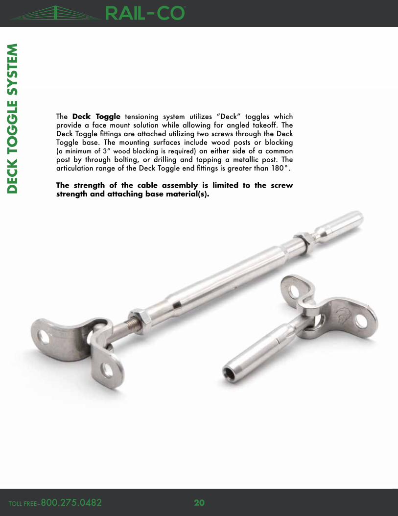
The Deck Toggle tensioning system utilizes “Deck” toggles which provide a face mount solution while allowing for angled takeoff. The Deck Toggle fittings are attached utilizing two screws through the Deck Toggle base. The mounting surfaces include wood posts or blocking (a minimum of 3” wood blocking is required) on either side of a common post by through bolting, or drilling and tapping a metallic post. The articulation range of the Deck Toggle end fittings is greater than 180°.
The strength of the cable assembly is limited to the screw strength and attaching base material(s).D
ECK
TO
GG
LE S
YST
EM

www.RAIL-CO.net21
Thread Wire Size Body Length Closed Length Open Length Screw Size Hole Spacing Part Number
1/4–28 UNF 1/8” 4–1/4” 6–3/8” 9–1/8” 1/4” 1–1/2” 14TTLL18DT
1/4–28 UNF 3/16” 4–1/4” 6–1/2” 9–1/4” 1/4” 1–1/2” 14TTLL316DT
5/16–24 UNF 3/16” 4–3/4” 7–1/8” 10–1/8” 5/16” 1–3/4” 516TTLL316DT
5/16–24 UNF 1/4” 4–3/4” 7–1/8” 10–1/4” 5/16” 1–3/4” 516TTLL14DT
3/8–24 UNF 1/4” 5–1/4” 7–3/4” 11–1/8” 3/8” 2” 38TTLL14DT
SWAGE FITTING
Deck Toggle Turnbuckle
CRIMP FITTING
DEC
K TO
GG
LE SYSTEM
Wire Size Length Screw Size Hole Spacing Part Number
1/8” 2–1/8” 1/4” 1–1/2” 14TJLL18DT
3/16” 1–5/8” 1/4” 1–1/2” 14TJLL316DT
3/16” 2–1/8” 5/16” 1–3/4” 516TJLL316DT
1/4” 2” 5/16” 1–3/4” 516TJLL14DT
1/4” 2–1/8” 3/8” 2” 38TJLL14DT
SWAGE FITTING
Deck Toggle Jaw
CRIMP FITTING
Thread Wire Size Body Length Closed Length Open Length Screw Size Hole Spacing Part Number
1/4–28 UNF 1/8” 4–1/4” 6–5/8” 9–3/8” 1/4” 1–1/2” 14TTCLL18DT
1/4–28 UNF 3/16” 4–1/4” 6–1/2” 9–1/4” 1/4” 1–1/2” 14TTCLL316DT
5/16–24 UNF 3/16” 4–3/4” 7–1/8” 10–1/8” 5/16” 1–3/4” 516TTCLL316DT
Wire Size Length Screw Size Hole Spacing Part Number
1/8” 2–1/8” 1/4” 1–1/2” 14TJCLL18DT
3/16” 1–13/16” 1/4” 1–1/2” 14TJCLL316DT
MECHANICAL FITTING
Thread Wire Size Body Length Closed Length Open Length Screw Size Hole Spacing Part Number
1/4–28 UNF 1/8” 4–1/4” 6–1/2” 8–3/4” 1/4” 1–1/2” 14TTHG18DT
1/4–28 UNF 3/16” 4–1/4” 6–1/2” 8–3/4” 1/4” 1–1/2” 14TTHG316DT
MECHANICAL FITTING
Wire Size Length Screw Size Hole Spacing Part Number
1/8” 1–3/4” 1/4” 1–1/2” 14TJHG18DT
3/16” 1–3/4” 1/4” 1–1/2” 14TJHG316DT
1x19 7x7 7x19
1x19 7x7 7x19

TOLL FREE–800.275.0482 22
The Round Head system’s extremely clean look comes from it’s lack of a turnbuckle and the fact that the fittings are concealed within the end posts. The system consists of an end fitting and a end tensioner. This system is intended for use in level runs.
The push-to-lock and pull-to-lock fittings can be installed “in the field” with no swaging or special tools required. These -lock fittings are designed to be used with 1x19LH wire rope only.
RO
UN
D H
EAD
SY
STEM

www.RAIL-CO.net23
Thread Wire Size Body Diameter Body Length Cap Diameter Rec. Hole Size Part Number
5/16–24 1/8” or 3/16” .437” 1.582” .537” 7/16” R-6-12
5/16–24 1/8” or 3/16” .437” 1.812” .537” 7/16” R-6-22
5/16–24 1/8” or 3/16” .437” 2.030” .537” 7/16” R-6-32
5/16–24 1/8” or 3/16” .437” 2.301” .537” 7/16” R-6-42
5/16–24 1/8” or 3/16” .437” 2.375” .537” 7/16” R-6-72
5/16–24 1/8” or 3/16” .437” 2.530” .537” 7/16” R-6-82
5/16–24 1/8” or 3/16” .437” 3.030” .537” 7/16” R-6-52
5/16–24 1/8” or 3/16” .437” 3.563” .537” 7/16” R-6-62
Round Head Stud Tensioner
RO
UN
D H
EAD
SYSTEM
Wire Size Body Diameter Body Length Cap Diameter Rec. Hole Size Part Number
1/8” .437” 1.562” .537” 7/16” PL-4
3/16” .437” 1.562” .537” 7/16” PL-6
PUSH TO LOCK
Round Head Fitting
Thread Thread Length Wire Size Body Diameter Body Length Part Number
5/16–24 1.562” 1/8” .437” 3.375” PLST-4
5/16–24 1.562” 3/16” .437” 3.375” PLST-6
PUSH TO LOCK
Round Head Stud
Wire Size Body Dia. Body Length Step Dia. Cap Dia. Total Length Rec. Hole Size Part Number
1/8” .437” 1.562” .537” .625” 1.825” 7/16” PUL-4
3/16” .437” 1.562” .537” .625” 1.825” 7/16” PUL-6
1/8” .437” 1.562” .537” .625” 1.825” 7/16” PUL-4-12
3/16” .437” 1.562” .537” .625” 1.825” 7/16” PUL_6-12
1/8” .437” 2.03” .537” .625” 2.266” 7/16” PUL-4-12-2.030
3/16” .437” 2.03” .537” .625” 2.266” 7/16” PUL-6-12-2.030
1/8” .437” 3.03” .537” .625” 3.266” 7/16” PUL-4-3.03C4
PULL TO LOCK
PUSH TO LOCK
1x19LH
1x19LH
1x19LH
1x19LH

TOLL FREE–800.275.0482 24
The Threaded Eye system is a time and headache saver when it comes to stairs or severly pitched railings. Both the Threaded Eye Turnbuckle, Fitting, and Tensioners have a 180° range of motion, making this system extremely versatile and removing the need to drill angled holes into your end posts.
The push-to-lock and pull-to-lock fittings can be installed “in the field” with no swaging or special tools required. These -lock fittings are designed to be used with 1x19LH wire rope only.TH
REA
DED
EY
E SY
STEM

www.RAIL-CO.net25
THREA
DED
EYE SY
STEM
Wire Size Body Diameter Body Length Head Thickness Hole Thread Hole Depth Part Number
1/8” .437” 2.450” .232” 1/4–28 .313” PL-TE4
3/16” .437” 2.450” .232” 1/4–28 .313” PL-TE6
PUSH TO LOCK
Threaded Eye End Fitting
SWAGE FITTING
Threaded JawTensioner
Thread Wire Size Body Dia. Body L. Thread L. Head W. Head Thick. Hole Th. Hole D. Part #
5/16–24 1/8” .5” 3.125” 2” .5” .233” 1/4–28 .44” A-JTE6
5/16–24 3/16” .5” 3.125” 2” .5” .233” 1/4–28 .44” A-JTE6
7/16–20 1/4” .625” 3.5” 2.5” .844” .295” 3/8–24 .68” A-JTE8
SWAGE FITTING
Thread Wire Size Body Dia. Closed L. Open L. Jaw W. Jaw D. Hole Th. Hole Dia. Part #
5/16–24 1/8” .5” 4.3” 5.99” .26” .56” 1/4–28 .26” A-J62
5/16–24 3/16” .5” 4.3” 5.99” .26” .56” 1/4–28 .26” A-J62
7/16–20 1/4” .625” 4.87” 6.43” .313” .75” 3/8–24 .39” A-J82
Thread Wire Size Body Dia. Closed Length Open Length Head Thick. Hole Thread Part Number
5/16–24 1/8” .437” 6.25” 7.5” .232” 1/4–20 PL-TB4
5/16–24 3/16” .437” 6.25” 7.5” .232” 1/4–20 PL-TB6
Threaded EyeTurnbucklePUSH TO LOCK
Wire Size Body Length Jaw Width Jaw Depth Hole Thread Part Number
1/8” 1.75” .26” .56” 1/4–28 F-J62
3/16” 1.75” .26” .56” 1/4–28 F-J62
1/4” 2.12” .39” .75” 3/8–24 F-J82
Fixed Jaw End FittingSWAGE FITTING
Threaded Eye Tensioner
Mounting Screw
Hardware Wire Size Part Number
1/8” SC-6
3/16” SC-6
1/4” SC-8
Swaged Ferrule
Wire Size Part Number
1/8” F-4
3/16” F-6
1/4” F-8
Ferrules are REQUIRED for all Swage fittings on this page.
1x19 7x7
1x19 7x7
1x19 7x7
1x191x19LH
1x19LH

TOLL FREE–800.275.0482 26
INV
ISIW
ARE®
SY
STEM
Invisiware® fittings are the ultimate in low-profile railing solutions. The Stud and Receiver are designed so that the tensioning happens within the post. There is no need for an external turnbuckle tensioner.
Invisiware® receivers are used with wood posts and metal tube or pipe. Pipe ends are counterbored so the full perimeter of the head rests on a flat surface in the pipe. The head rests on the outside wall of a flat-sided post. A plastic washer is included and acts as a scratch barrier between the receiver and the metal post. For wood posts, the receiver can rest against the outside of the post or the post can be counterbored with the receiver head recessed in the post. For wood applications, don’t forget to order 7/16 SAE washers (pg. 31).

www.RAIL-CO.net27
Thread Wire Size Body Dia. Body Length Cap Diameter Rec. Hole Size Part Number
5/16–24 1/8” .437” 1.562” .537” 7/16” R-6-12
5/16–24 3/16” .437” 1.562” .537” 7/16” R-6-12
5/16–24 1/8” .437” 1.812” .537” 7/16” R-6-22
5/16–24 3/16” .437” 1.812” .537” 7/16” R-6-22
7/16–20 1/4” .531” 1.812” .646” 17/32” R-8-22
5/16–24 1/8” .437” 2.030” .537” 7/16” R-6-32
5/16–24 3/16” .437” 2.030” .537” 7/16” R-6-32
7/16–20 1/4” .531” 2.030” .646” 17/32” R-8-32
5/16–24 1/8” .437” 2.301” .537” 7/16” R-6-42
5/16–24 3/16” .437” 2.301” .537” 7/16” R-6-42
7/16–20 1/4” .531” 2.301” .646” 17/32” R-8-42
5/16–24 1/8” .437” 2.375” .537” 7/16” R-6-72
5/16–24 3/16” .437” 2.375” .537” 7/16” R-6-72
5/16–24 1/8” .437” 2.530” .537” 7/16” R-6-82
5/16–24 3/16” .437” 2.530” .537” 7/16” R-6-82
5/16–24 1/8” .437” 3.030” .537” 7/16” R-6-52
5/16–24 3/16” .437” 3.030” .537” 7/16” R-6-52
7/16–20 1/4” .531” 3.030” .646” 17/32” R-8-52
Invisiware® Threaded Receiver
INV
ISIWA
RE
® SYSTEM
Thread Wire Size Body Diameter* Part Number
5/16–24 1/8” .250” S-4
5/16–24 3/16” .250” S-6
7/16–20 1/4” .375” S-8
SWAGE FITTING
Invisiware® Threaded Stud
Wire Size Body Dia.* Body Length Shoulder Dia. Cap Dia. Part Number
1/8” .250” .750” .437” .537” RF-4
3/16” .250” .750” .437” .537” RF-6
1/4” .375” 1.00” .531” .646” RF-8
SWAGE FITTING
Invisiware® Radius Ferrule
*after swage
*after swage
1x19 7x7
1x19 7x7For use on a stairwell, you do not have to drill holes at an angle. Invisiware® receivers can accept an angle of up to 35°.

TOLL FREE–800.275.0482 28
THREA
DED
BO
LT S
YST
EM
Thread Wire Size Body Dia. Body L. Thread L. End Thread Length Part #
5/16–24 1/8” .5” 3.125” 2” .375” A-JTB6
5/16–24 3/16” .5” 3.125” 2” .375” A-JTB6
7/16–20 1/4” .625” 3.5” 2.5” .375” A-JTB8
SWAGE FITTING
Wire Size Body Diameter Body Length Thread Thread Length Part Number
1/8” .437” 2.5” 5/16–24 2.5” PL-TH4
3/16” .437” 2.5” 5/16–24 2.5” PL-TH6
Threaded Bolt End FittingPUSH TO LOCK
Threaded Bolt Tensioner
The Threaded Bolt system is another tasteful railing system. The Threaded Bolt Tensioner and End Fitting thread into pre-drilled and tapped holes in your end posts. When you are using at least Schedule 80 pipe or square tubing with a minimum 1/4” wall, you can mount these fittings directly into the post with no need for special brackets or extra welding...A real time and money saver.
1x19 7x7
1x19LH
Swaged Ferrule
Wire Size Part Number
1/8” F-4
3/16” F-6
1/4” F-8
Ferrules are REQUIRED for all Swage fittings on this page.

www.RAIL-CO.net29
TRELLIS SY
STEM H
ARD
WA
RE
Trellis System hardware is available for 1/8”, 3/16”, and 1/4” wire diameters. The system is designed to accommodate cables attaching perpendicularly to each other to form a grid pattern.
Trellis Post
Wire Size Length Body Dia. Base Dia. Through Holes Hole Dia. Mount Screw Part Number
1/8” 3” 3/4” 1” 1 17/64” 3/8” LP63-2
1/8” 4” 3/4” 1” 1 17/64” 3/8” LP64-2
1/8” 4” 3/4” 1” 2 17/64” 3/8” LP63-4
1/8” 4” 3/4” 1” 2 17/64” 3/8” LP64-4
3/16–1/4” 4” 1” 1–1/4” 1 25/64” 3/8” LP104-2ASSY
3/16–1/4” 4” 1” 1–1/4” 2 25/64” 3/8” LP104-4ASSY
POST BASE
Outside Dia. Thickness Mount Screw Siz. Part Number
1–3/4” 1/4” 3/8” LP6-BASE
WIDE POST BASE (for use with LP6x-x trellis posts)
Thread Size Length Part Number
3/8–16 UNC 2” SC38CS2
3/8–16 UNC 3” SC38CS3
MOUNT SCREWS
Thread Size Part Number
3/8–16 UNC SC38CS2
3/8–16 UNC SC38CS3
CROSS CLAMPS
Cross Clamps are used in conjunction with trellis posts. They are used in two different ways: To act as a stiffener at the cable intersection points where no post exists and to attach horizontal/vertical interior cables to the perimeter cables.
Cross Clamp

HEX NUT/ACORN NUT
ACORN NUT
DOME NUT
BALL END
ADJUSTABLE BALL (AJB1)
ADJUSTABLE BALL (
AJB)
BEVEL
WASHER
Designed for use with many of our end fitting options without post modifications. Angles provided will work with most conventional stair systems.
Bevel Washers
Inner Dia. Out. Dia. Bevel Angle Part #
1/4” 1/2” 31° BW5
25/64” 5/8” 31° BW6
1/4” 5/8” 31° BW7
5/16” 5/8” 31° BW8
1/4” 1/2” 37° BW9
25/64” 5/8” 37° BW10
1/4” 5/8” 37° BW11
5/16” 5/8” 37° BW12
7/16” 5/8” 31° BW13
7/16” 5/8” 37° BW14
The Dome Nuts serve as a cap on the Termination Stud hardware (pg. 12), creating an attachment point on the end verticals/posts.
Dome Nuts
Thread Size Out. Dia. Thickness Part #
1/4–28 UNF RH 6/16” 1/4” DN6
5/16–24 UNF RH 3/4” 9/32” DN8
THROUGH HOLE
Thread Size Out. Dia. Thickness Part #
1/4–28 UNF RH 6/16” 1/4” DN6S
5/16–24 UNF RH 3/4” 9/32” DN8S
NO THROUGH HOLE
ACCES
SORIE
S
TOLL FREE–800.275.0482 30
ONLY FOR USE WITH SYSTEMS ON PGS. 8-21
Wire Size Bevel Angle Part #
1/8” or 3/16” 30–33° BW32–6
1/8” or 3/16” 34–36° BW35–6
1/8” or 3/16” 37–39° BW38–6
1/4” 30–33° BW32–8
1/4” 34–36° BW35–8
1/4” 37–39° BW38–8
ONLY FOR USE WITH SYSTEMS ON PGS. 22-28
°

www.RAIL-CO.net31
ACCESSO
RIES
Adjustable Ball Fittings are an excellent choice for most angle compensation applications. An 11/16” hole in the end verticals/posts acts as a mounting socket. Flat bar applications utilize an 11/16” outside diameter chamfer.
Adjustable Ball Fittings
Ball Dia. Style Hole Dia. Part Number
3/4” Term. Stud 3/8” AJB
3/4” Threaded Stud 3/8” AJB1
Washers
Nominal Size Part Number
3/16” 10WAS
1/4” 14WAS
5/16” 516WAS
3/8” 38WAS
1/2” 12WAS
5/8” 58WAS
3/4” 34WAS
7/8” 78WAS
1” 1WAS
FLAT
Nominal Size Part Number
3/16” 10WAS
1/4” 14WAS
5/16” 516WAS
3/8” 38WAS
LOCK
Nominal Size Part Number
3/16” 10WAS
1/4” 14WAS
5/16” 516WAS
3/8” 38WAS
FENDER
The thread-on Ball End Fittings are available in both 1/4–28 and 5/16–24 thread configurations. Both options are designed to be used with the Threaded Termination Studs and Threaded Termina-tion Stud Turnbuckle (pg. 16) assemblies as well as our Surface and Back Mounting Ball and Socket System. (Post hole should be 1/2”).
Ball End Fittings
Thread Size Outside Dia. Part Number
1/4–28 UNF RH 5/8” BALL6
5/16–24 UNF RH 5/8” BALL8
Ball Dia. Thick. Post Hole Dia.
Cap Thick. Cap Dia. Pivot
Angle Slot Part #
5/8” 9/32” 3/4” 3/16” 7/8” 40° No BCM6
5/8” 9/32” 3/4” 3/16” 7/8” 40° Y–1/4” BCM6-C
BACK MOUNT
Ball Dia. Out. Dia Thick. Length Screw Size Pivot Angle Part #
5/8” 7/8” 1” 13/16” 1/4” 40° BCFM6-C
5/8” 7/8” 1” 13/16” 6mmx1.25 thread 40° BCFM6
SURFACE MOUNT
Surface and Back Mounting Ball Sockets

TOLL FREE–800.275.0482 32
ACCES
SORIE
S
Wire Size Pin Size Fork Depth Length Part Number
1/8” 1/4” 1–1/2” 2.756” SF03
3/16” 3/8” 2” 3.819” SF05
1/4” 7/16” 2–1/2” 4.449” SF07
1/4” 1/2” 2–1/2” 4.700” SF07A
Swage Forks
Swage to Swage Turnbuckles are utilized in longer cable runs every 30-40’ to compensate for cable stretch so that proper tensioning can be achieved. Additionally, these turnbuckles can also be used to achieve a certain desired look in shorter cable runs. Depending on the look desired, positioning of the turnbuckles is up to the designer. These fittings are fully compatible with any of the available termination style fittings.
Swage to Swage Turnbuckle
Thread Wire Size Body Length Closed Length Open Length Part Number
10–32 UNF 1/8” 3–1/2” 4–1/2” 6–7/8” 10TTLL18SS
10–32 UNF 1/8” 4–1/4” 5–3/8” 8–1/8” 14TTLL18SS
1/4–28–UNF 3/16” 4–1/4” 5–1/2” 8–1/2” 14TTLL316SS
5/16–24 UNF 3/16” 4–3/4” 6–1/2” 9–3/8” 516TTLL316SS
5/16–24 UNF 1/4” 4–3/4” 6–1/4” 9–5/8” 516TTLL14SS
3/8–24 UNF 1/4” 5–1/4” 6–3/4” 10–1/4” 38TTLL14SS
SWAGE FITTING
Thread Wire Size Body Length Closed Length Open Length Part Number
1/4–28 UNF 1/8” 4–1/4” 5–3/4” 8–3/4” 14TTCLL18SS
1/4–28 UNF 3/16” 4–1/4” 5–3/8” 8–1/4” 14TTCLL316SS
Thread Body Length Part Number
10–32 UNF 2–1/4” 10TB2
10–32 UNF 3–1/2” 10TB
1/4–28–UNF 2–3/4” 14TB2
1/4–28–UNF 4–1/4” 14TB
5/16–24 UNF 5” 516TB
3/8–24 UNF 5–1/4” 38TB
Tubular Turnbuckle Bodies
CRIMP FITTING
1x19 7x7
1x19 7x7

www.RAIL-CO.net33
ACCESSO
RIES
Grommets help prevent rust in exterior applications or where moisture is a factor. Grommets are installed after your railing is painted/powder-coated but before you run the lines.
Cable Grommets/Bushings
Wire Size Post Material Type of Post Part Number
1/8” or 3/16” Schedule 40 Pipe Intermediate (level) G–C6–1
1/4” Schedule 40 Pipe Intermediate (level) G–C8–1
1/8” or 3/16” .120” wall Tubing Intermediate (level) G–C6–2
1/4” .120” wall Tubing Intermediate (level) G–C8–2
1/8” or 3/16” .250” wall Tubing Intermediate (level) G–C6–4
1/4” .250” wall Tubing Intermediate (level) G–C8–4
1/8” or 3/16” Schedule 80 Pipe End Post G–C6–3
1/4” Schedule 80 Pipe End Post G–C8–3
1/8” or 3/16” .250” wall Tubing End Post G–C6–4
1/4” .250” wall Tubing End Post G–C8–4
1/8” or 3/16” Schedule 40 Pipe Intermediate (angle up to 37°) GI–C6–1
1/4” Schedule 40 Pipe Intermediate (angle up to 37°) GI–C8–1
1/8” or 3/16” .120” wall Tubing Intermediate (angle up to 37°) GI–C6–2
1/4” .120” wall Tubing Intermediate (angle up to 37°) GI–C8–2
1/8” or 3/16” .250” wall Tubing Intermediate (angle up to 37°) GI–C6–4
1/4” .250” wall Tubing Intermediate (angle up to 37°) GI–C8–4
GROMMETS ARE ONLY FOR USE WITH SYSTEMS ON PGS. 22-28.
Wire Size Post Hole Size Type of Post Part Number
1/8” 23/64” Level BUSHING–4MMB
3/16” 25/64” Level BUSHING–6MMB
1/8” 23/64” 31° BUSHING–4MMAB
3/16” 25/64” 31° BUSHING–6MMAB
BUSHINGS ARE ONLY FOR USE WITH SYSTEMS ON PGS. 8-21.
Cable Release Tool–Part Number #PL–KEY
Releases cable from Push-to-Lock and Pull-to-Lock type fittings before lines are tensioned.
Installation Kit–Part Number # GROMMET TOOL SET
Place grommet on tool, align with hole, then tap gen-tly with a hammer...Kit is needed to properly install grommets from top section of chart (Part #’s beginning with G).
Nuts
Thread Size Part Number
10-32 UNF 10LNL
10-32 UNF 10LNR
1/4–28 UNF 14LNL
1/4–28 UNF 14LNR
5/16–24 UNF 516LNL
5/16–24 UNF 516LNR
3/8–24 UNF 38LNL
3/8–24 UNF 38LNR
ACORNNominal Size Part Number
1/4–28 UNF RH 14CAP
5/16–24 UNF RH 516CAP
3/8–24 UNF RH 38CAP
HEX

TOLL FREE–800.275.0482 34
A real time and money saver! The threaded tab screws into a drilled and tapped hole on the inside wall of an end post. No need for weld-ing... Be sure to use at least schedule 80 pipe or square tubing with a minimum 1/4” thick wall.
Threaded Tabs
Wire Size Thread Thread Length Body Length Hole Dia. Hole Depth Tab Thickness Part #
1/8” 5/16–24 .375” 1.250” .265” .313” .233” TT–6B
3/16” 5/16–24 .375” 1.250” .265” .313” .233” TT–6B
1/4” 5/16–24 .375” 1.625” .390” .375” .295” TT–8B
ACCES
SORIE
S
Extended length, same as above except there is no need to tap the hole in your end post (3/8” hole for 1/8” or 3/16” fittings and 9/16” hole for 1/4” fittings). Cut to desired length and secure to end post with an acorn nut (pg. 33) and thread sealant.
Wire Size Thread Thread Length Body Length Hole Dia. Hole Depth Tab Thickness Part #
1/8” 3/8–24 2.5” 3.923” .265” .313” .233” TT–6B–L
3/16” 3/8–24 2.5” 3.923” .265” .313” .233” TT–6B–L
THREADED, EXTENDED LENGTH
THREADED
A convenient, easy-to-install means for attaching a Threaded Eye or Threaded Jaw tensioner to a wood post.
Wire Size Thread Length Hole Depth Tab Thickness Drill Size Reqd. Part #
1/8” 1.5” .420” .232”/.228” 17/64” LE-6
3/16” 1.5” .420” .232”/.228” 17/64” LE-6
1/4” 1.5” 1.188” .255”/.265” 3/8” LE-8
Lag Eye Bolt
Wire Size Thread Length Hole Depth Tab Thickness Drill Size Reqd. Part #
1/8” 3.0” .420” .232”/.228” 17/64” LE-6L
3/16” 3.0” .420” .232”/.228” 17/64” LE-6L
EXTENDED LENGTH

www.RAIL-CO.net35
RA
ILING
SYSTEM
WO
RK
SHEET
1 Sq
uare
= _
__ fo
ot/f
eet
*Worksheet is intended only as a planning aid. To ensure your project meets code, check with your local authority.
Use this blank worksheet to help plan out your project.* You can use this sheet to map out an overhead view, or an a side elevation view (for things like stairs, etc.).Make as many copies of this sheet as you need. Feel free to send your plan ideas along with the worksheet on the following page to give us the best idea of what you’re working on.
Customer Name ________________________________________

TOLL FREE–800.275.0482 36
RA
ILIN
G S
YST
EM W
ORK
SHEE
T
1) What type of wire rope will be used in your project?
2) What size of wire rope will be used in your project?
6) How many lines per segment do you need to plan for (round your answers up)? a. _____ inches/3 inches= ______ lines needed to meet code* b. _____ inches/3 inches= ______ number of lines needed c. _____ inches/3 inches= ______ number of lines needed d. _____ inches/3 inches= ______ number of lines needed
*Worksheet is intended only as a planning aid. To ensure your project meets code, check with your local authority.
3) How many railing segments will your project have? What are their lengths? Segment a. _____ inches Segment b. _____ inches Segment c. _____ inches Segment d. _____ inches
7) Choose your desired/needed fittings from pgs. 8-28: a. End Fitting Part # __________, Tensioner Part # __________, End Fitting #2 Part # (if needed) __________. End Fitting Body Length ______, Tensioner Open Length ______, End Fitting #2 Body Length (if needed) ______. TOTAL Fitting Length _______ inches
b. End Fitting Part # __________, Tensioner Part # __________, End Fitting #2 Part # (if needed) __________. End Fitting Body Length ______, Tensioner Open Length ______, End Fitting #2 Body Length (if needed) ______. TOTAL Fitting Length _______ inches
c. End Fitting Part # __________, Tensioner Part # __________, End Fitting #2 Part # (if needed) __________. End Fitting Body Length ______, Tensioner Open Length ______, End Fitting #2 Body Length (if needed) ______. TOTAL Fitting Length _______ inches
d. End Fitting Part # __________, Tensioner Part # __________, End Fitting #2 Part # (if needed) __________. End Fitting Body Length ______, Tensioner Open Length ______, End Fitting #2 Body Length (if needed) ______. TOTAL Fitting Length _______ inches
8) How much wire rope are you going to need to order? a. length from #3a ______ inches–TOTAL Fitting Length from #7a ______ inches= ______ inches b. length from #3b ______ inches–TOTAL Fitting Length from #7b ______ inches= ______ inches c. length from #3c ______ inches–TOTAL Fitting Length from #7c ______ inches= ______ inches d. length from #3d ______ inches–TOTAL Fitting Length from #7d ______ inches= ______ inches
TOTAL Wire Rope Needed ______ inches
5) How tall will each railing segment be? a. _____ inches b. _____ inches c. _____ inches d. _____ inches
4) How many Intermediate Posts do you need to plan for (round your answers up)? a. _____ inches from #3a/48 inches= ______ posts needed b. _____ inches from #3b/48 inches= ______ posts needed c. _____ inches from #3c/48 inches= ______ posts needed d. _____ inches from #3d/48 inches= ______ posts needed
This worksheet can be faxed or e-mailed to [email protected]. This form is also available online at www.RAIL-CO.net.
9) How many fittings are you going to need to order? a. End Fitting= # of Lines from #6a ______, Tensioners= # of Lines from #6a ______, End Fitting #2 (if needed)= # of Lines from #6a ______ b. End Fitting= # of Lines from #6b ______, Tensioners= # of Lines from #6b ______, End Fitting #2 (if needed)= # of Lines from #6b ______ c. End Fitting= # of Lines from #6c ______, Tensioners= # of Lines from #6c ______, End Fitting #2 (if needed)= # of Lines from #6c ______ d. End Fitting= # of Lines from #6d ______, Tensioners= # of Lines from #6d ______, End Fitting #2 (if needed)= # of Lines from #6d ______
TOTAL End Fittings _______, TOTAL Tensioners _______, TOTAL End Fitting #2 _______
Based on your drawing (from the previous page, or otherwise), complete the following questions:
7x71x19
3/16”1/8” 1/4”
9) Are any accessories needed (Angle Bevels, Nuts, Washers, Trellis Hardware, Adjustable Ball Fittings, etc.)? a. Part # ___________ Description ___________________ Qty. ______, Part # ___________ Description ___________________ Qty. ______, Part # ___________ Description ___________________ Qty. ______, Part # ___________ Description ___________________ Qty. ______
b. Part # ___________ Description ___________________ Qty. ______, Part # ___________ Description ___________________ Qty. ______, Part # ___________ Description ___________________ Qty. ______, Part # ___________ Description ___________________ Qty. ______
c. Part # ___________ Description ___________________ Qty. ______, Part # ___________ Description ___________________ Qty. ______, Part # ___________ Description ___________________ Qty. ______, Part # ___________ Description ___________________ Qty. ______
d. Part # ___________ Description ___________________ Qty. ______, Part # ___________ Description ___________________ Qty. ______, Part # ___________ Description ___________________ Qty. ______, Part # ___________ Description ___________________ Qty. ______
Name ________________________ Contact Information ________________________
7x19

photo by George Cott/Ed Carpenter
photo by Ed Carpenter

`
A Division of West Coast Wire Rope & Rigging, Inc., facilities in WA, OR, and CA.
TOLL-FREE–800.275.0482FAX–[email protected]