APSA Working Group Tier II Qualfied Facility SPCC … 10, 2010 · TIER II QUALIFIED FACILITY SPCC...
29
CALIFORNIA CUPA FORUM – APSA WORKING GROUP TIER II QUALIFIED FACILITY SPCC PLAN TEMPLATE Disclaimer This Tier II Spill Prevention Control and Countermeasure (SPCC) plan template has been developed by the CalCUPA Forum Board’s APSA Working Group and is intended to serve as an SPCC Plan template for use by Tier II Qualified Facilities meeting the applicability criteria of 40 CFR §112.3(g)(2). This Tier II SPCC Plan template is modeled after the US EPA Tier I SPCC plan template from 40 CFR Part 112 Appendix G, but has been modified to incorporate the 40 CFR §112.6(b) requirements for Tier II Qualified Facilities. Although the 40 CFR 112 SPCC rules do not specifically provide for, nor has US EPA developed, a plan template for use by Tier II Qualified Facilities, this Tier II plan template to the best of our knowledge would allow a Tier II Qualified Facility properly completing the template to meet the requirements for preparation of a written SPCC Plan as specified for Tier II Qualified Facilities. This template has not been reviewed or approved by the US EPA though the template has been shared with the US EPA. The use by any facility of this template is optional. Neither this template as a whole or any specific element of the template substitutes for any regulatory provision or regulation, nor is the template a regulation itself. In the event of a conflict between the template or any element and any statute or regulation, this template would not be controlling. Thus, it does not impose legally binding requirements on the State, Unified Program Agencies, or the regulated community, and might not apply to a particular facility or situation based upon certain circumstances. If your SPCC plan deviates from this template, you will need to ensure that it meets all of the required 40 CFR 112 elements and requirements applicable to a Tier II Qualified Facility. Proper completion of this template is only one element of a tank facility’s compliance with 40 CFR 112 and the Aboveground Petroleum Storage Act (HSC Chapter 6.67). Facilities are reminded that, in addition to preparing the written SPCC Plan, the applicable requirements of the 40 CFR 112 SPCC rule and HSC Chapter 6.67 must be implemented at the facility, including implementation of the written SPCC Plan. A website to learn more on the SPCC requirements is: http://www.epa.gov/emergencies/content/spcc/. If you have any concerns about meeting the requirements of a Tier II Qualified Facility SPCC plan, contact the US EPA Region IX for assistance or clarifications. Instructions to Complete this Template This template is intended to help the owner or operator of a Tier II qualified facility develop a self-certified Spill Prevention, Control, and Countermeasure (SPCC) Plan. To use this template, your facility must meet all of the applicability criteria of a Tier II qualified facility listed under §112.3(g)(2) of the SPCC rule. This template provides every SPCC rule requirement necessary for a Tier II qualified facility, which you must address and implement. You may use this template to comply with the SPCC regulation or use it as a model and modify it as necessary to meet your facility-specific needs. If you modify the template, your Plan must include a section cross-referencing the location of each applicable requirement of the SPCC rule and you must ensure that your Plan is an equivalent Plan that meets all applicable rule requirements of 40 CFR 112. You may complete this template either electronically or by hand on a printed copy. This document is based on the US EPA Tier I SPCC Plan template for qualified facilities. a No substantive changes have been made. Please note that a "Not Applicable" ("N/A") column is included in both Table G-10 (General Rule Requirements for Onshore Facilities) and Table G-11 (General Rule Requirements for Onshore Oil Production Facilities). The template summarizes in each section the specific requirements of the 40 CFR 112 SPCC rule. Each requirement has to the right an associated checkbox. Unless marked with an “N/A”, the checkboxes in the right hand column serve as an affirmation/verification of compliance by the facility to the stated compliance requirement. The "N/A" column should help you complete your self-certification when a required rule element does not apply to your facility. Use of the "N/A" column is optional and is not required by rule. In addition to the affirmative checkbox, several sections of the template also contain tables or narrative text fields. For these sections, in addition to checking the box to affirm your compliance with the stated requirement, you must complete the tables or narrative text field with the requested information. a Please note that the use of this template is not mandatory for a Tier II qualified facility. You may also meet the SPCC Plan requirement by preparing a satisfactory Tier II qualified facility Plan or preparing a satisfactory Plan that is certified by a Professional Engineer. Further information on the requirements of these methods can be found in 40 CFR part 112.6(a)(2). If you use any of these alternative methods you must include a cross reference in your Plan that shows how the equivalent Plan meets all applicable 40 CFR part 112 requirements.
Transcript of APSA Working Group Tier II Qualfied Facility SPCC … 10, 2010 · TIER II QUALIFIED FACILITY SPCC...
CALIFORNIA CUPA FORUM – APSA WORKING GROUPTIER II QUALIFIED FACILITY SPCC PLAN TEMPLATE
DisclaimerThis Tier II Spill Prevention Control and Countermeasure (SPCC) plan template has been developed by the CalCUPA ForumBoard’s APSA Working Group and is intended to serve as an SPCC Plan template for use by Tier II Qualified Facilities meetingthe applicability criteria of 40 CFR §112.3(g)(2). This Tier II SPCC Plan template is modeled after the US EPA Tier I SPCC plantemplate from 40 CFR Part 112 Appendix G, but has been modified to incorporate the 40 CFR §112.6(b) requirements for Tier IIQualified Facilities.
Although the 40 CFR 112 SPCC rules do not specifically provide for, nor has US EPA developed, a plan template for use by TierII Qualified Facilities, this Tier II plan template to the best of our knowledge would allow a Tier II Qualified Facility properlycompleting the template to meet the requirements for preparation of a written SPCC Plan as specified for Tier II QualifiedFacilities.
This template has not been reviewed or approved by the US EPA though the template has been shared with the US EPA. Theuse by any facility of this template is optional. Neither this template as a whole or any specific element of the templatesubstitutes for any regulatory provision or regulation, nor is the template a regulation itself. In the event of a conflict betweenthe template or any element and any statute or regulation, this template would not be controlling. Thus, it does not imposelegally binding requirements on the State, Unified Program Agencies, or the regulated community, and might not apply to aparticular facility or situation based upon certain circumstances. If your SPCC plan deviates from this template, you will need toensure that it meets all of the required 40 CFR 112 elements and requirements applicable to a Tier II Qualified Facility.
Proper completion of this template is only one element of a tank facility’s compliance with 40 CFR 112 and the AbovegroundPetroleum Storage Act (HSC Chapter 6.67). Facilities are reminded that, in addition to preparing the written SPCC Plan, theapplicable requirements of the 40 CFR 112 SPCC rule and HSC Chapter 6.67 must be implemented at the facility, includingimplementation of the written SPCC Plan.
A website to learn more on the SPCC requirements is: http://www.epa.gov/emergencies/content/spcc/. If you have anyconcerns about meeting the requirements of a Tier II Qualified Facility SPCC plan, contact the US EPA Region IX for assistanceor clarifications.
Instructions to Complete this TemplateThis template is intended to help the owner or operator of a Tier II qualified facility develop a self-certified Spill Prevention,Control, and Countermeasure (SPCC) Plan. To use this template, your facility must meet all of the applicability criteria of a Tier IIqualified facility listed under §112.3(g)(2) of the SPCC rule. This template provides every SPCC rule requirement necessary fora Tier II qualified facility, which you must address and implement.
You may use this template to comply with the SPCC regulation or use it as a model and modify it as necessary to meet yourfacility-specific needs. If you modify the template, your Plan must include a section cross-referencing the location of eachapplicable requirement of the SPCC rule and you must ensure that your Plan is an equivalent Plan that meets all applicable rulerequirements of 40 CFR 112.
You may complete this template either electronically or by hand on a printed copy. This document is based on the US EPA Tier ISPCC Plan template for qualified facilities.a No substantive changes have been made. Please note that a "Not Applicable"("N/A") column is included in both Table G-10 (General Rule Requirements for Onshore Facilities) and Table G-11 (GeneralRule Requirements for Onshore Oil Production Facilities).
The template summarizes in each section the specific requirements of the 40 CFR 112 SPCC rule. Each requirement has to theright an associated checkbox. Unless marked with an “N/A”, the checkboxes in the right hand column serve as anaffirmation/verification of compliance by the facility to the stated compliance requirement. The "N/A" column should help youcomplete your self-certification when a required rule element does not apply to your facility. Use of the "N/A" column is optionaland is not required by rule. In addition to the affirmative checkbox, several sections of the template also contain tables ornarrative text fields. For these sections, in addition to checking the box to affirm your compliance with the stated requirement,you must complete the tables or narrative text field with the requested information.
a Please note that the use of this template is not mandatory for a Tier II qualified facility. You may also meet the SPCC Plan requirement by preparing asatisfactory Tier II qualified facility Plan or preparing a satisfactory Plan that is cert ified by a Professional Engineer. Further information on therequirements of these methods can be found in 40 CFR part 112.6(a)(2). If you use any of these alternative methods you must include a crossreference in your Plan that shows how the equivalent Plan meets all applicable 40 CFR part 112 requirements.

DRAFT Ver. 1-C-doc-4-5-10
Page ii Tier II Qualified Facility SPCC Plan
All Tier II qualified facility self-certifiers must complete Sections I, II, and III. Additionally, the owner or operator of an:
Onshore facility (excluding production) must complete Section A.
Onshore oil production facility (excluding drilling and workover facilities) must complete Section B.
Onshore oil drilling and workover facility must complete Section C.
Complete and include with your Plan the appropriate attachments. You should consider printing copies of the attachments foruse in implementing the SPCC Plan (e.g. Attachment 3.1 - Inspection Log & Schedule; Attachment 4 - DischargeNotification Form).
To complete the template, check the box next to the requirement to indicate that it has been adequately addressed. Either write“N/A” in the column or check the box under the “N/A” column to indicate those requirements that are not applicable to the facility.Where a section requires a description or listing, write in the spaces provided (or attach additional descriptions if more space isneeded).
Below is a key for the colors used in the section headers:
Sections I, II, and III: Required for all Tier I i qualified facilities
Section A: Onshore facilities (excluding production)
Section B: Onshore oil production facilities (excluding drilling and workover facilities)
Section C: Onshore oil drilling and workover facilities
Attachments: 1 - Five Year Review and Technical Amendment Logs2 - Oil Spill Contingency Plan and Checklist3 - Inspections, Dike Drainage and Personnel Training Logs4 - Discharge Notification Form
After you have completed all appropriate sections, certify and date your Plan, and then implement it by the compliance date(currently November 10, 2010). If your facility was in operation before August 16, 2002, and you do not already have a Plan,then implement this template immediately. Conduct inspections and tests in accordance with the written procedures that youhave developed for your facility. You must keep with the SPCC Plan a record of these inspections and tests, signed by theappropriate supervisor or inspector, for a period of three years.
Do not forget to periodically review your Plan (at least once every five years) or to update it when you make changes to yourfacility. You must prepare amendments within six months of the facility change, and implement them as soon as possible, butnot later than six months following preparation of any amendment.
In the event that your facility releases oil to navigable waters or adjoining shorelines, immediately call the National ResponseCenter (NRC) at 1-800-424-8802. The NRC is the federal government's centralized reporting center, which is staffed 24 hoursper day by U.S. Coast Guard personnel. Additional state and local release/discharge reporting requirements also apply.
DRAFT Ver. 1-C-doc-4-5-10
Page 1 Tier II Qualified Facility SPCC Plan
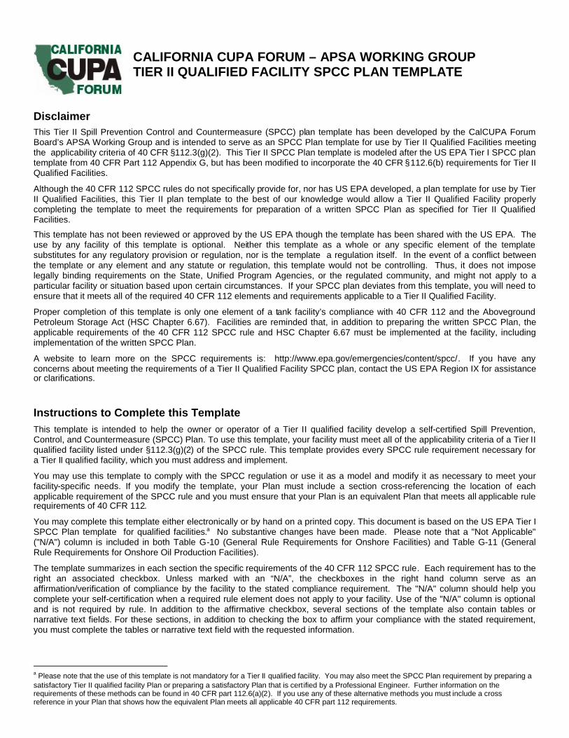
This template constitutes the SPCC Plan for the facility, when completed and signed by the owner or operator of afacility that meets the applicability criteria in §112.3(g)(2). This template addresses the requirements of 40 CFR part 112.Maintain a complete copy of the Plan at the facility if the facility is normally attended at least four hours per day, or for afacility attended fewer than four hours per day, at the nearest field office. When making operational changes at a facilitythat are necessary to comply with the rule requirements, the owner/operator should follow state and local requirements(such as for permitting, design and construction) and obtain professional assistance, as appropriate.
Facility Description
I. Self-Certification Statement (§112.6(b)(2))The owner or operator of a facility certifies that each of the following is true in order to utilize this template to comply
with the SPCC requirements:
I certify that the following is accurate:
1. I am familiar with the applicable requirements of 40 CFR part 112;2. I have visited and examined the facility;3. This Plan was prepared in accordance with accepted and sound industry practices and standards, and with the
requirements of 40 CFR part 112;4. Procedures for required inspections and testing have been established;5. I will fully implement the Plan;6. This facility meets the following qualification criteria (under §112.3(g)(2)):
a. The aggregate aboveground oil storage capacity of the facility is 10,000 U.S. gallons or less; andb. The facility has had no single discharge as described in §112.1(b) exceeding 1,000 U.S. gallons and no
two discharges as described in §112.1(b) each exceeding 42 U.S. gallons within any twelve month periodin the three years prior to the SPCC Plan self-certification date, or since becoming subject to 40 CFR part112 if the facility has been in operation for less than three years (not including oil discharges as describedin §112.1(b) that are the result of natural disasters, acts of war, or terrorism).
7. The Plan does not deviate from any requirement of this part as allowed by §112.7(a)(2) and 112.7(d), or includean exemption/measures pursuant to §112.9(c)(6) for produced water containers and any associated piping andappurtenances downstream from the container, except as provided in §112.6(b)(3); and
8. This Plan and individual(s) responsible for implementing this Plan have the full approval of management and Ihave committed the necessary resources to fully implement this Plan.
Facility Name
Facility Address
City State ZIP
County Tel. Number ( ) -
Owner or Operator Name
Owner or Operator Address
City State ZIP
County Tel. Number ( ) -
Facility Name:
Tier II Qualified Facility SPCC Plan

DRAFT Ver. 1-C-doc-4-5-10
Page 2 Tier II Qualified Facility SPCC Plan
I also understand my other obligations relating to the storage of oil at this facility, including, among others:
1. To report any oil discharge to navigable waters or adjoining shorelines to the appropriate authorities. Notificationinformation is included in this Plan.
2. To review and amend this Plan whenever there is a material change at the facility that affects the potential for anoil discharge, and at least once every five years. Reviews and amendments are recorded in an attached log [SeeFive Year Review Log and Technical Amendment Log in Attachments 1.1 and 1.2.]
3. Optional use of a contingency plan. A contingency plan:a. May be used in lieu of secondary containment for qualified oil-filled operational equipment, in accordance
with the requirements under §112.7(k), and;b. Must be prepared for flowlines and/or intra-facility gathering lines which do not have secondary
containment at an oil production facility, and;c. Must include an established and documented inspection or monitoring program; must follow the provisions
of 40 CFR part 109; and must include a written commitment of manpower, equipment and materials toexpeditiously remove any quantity of oil discharged that may be harmful. If applicable, a copy of thecontingency plan and any additional documentation will be attached to this Plan as Attachment 2.
I certify that I have satisfied the requirement to prepare and implement a Plan under §112.3 and all of the requirementsunder §112.6(b). I certify that the information contained in this Plan is true.
Signature Title:
Name Date: / / 20
II. Record of Plan Review and Amendments Technical Amendments, Applicable Requirements and ProfessionalEngineer Certifications (§112.5(a), (d) and 112.6(b)(2))
Table G-1 Five Year Review and Technical Amendments (§§112.5(a) and 112.6(b)(2) and (3))This SPCC Plan will be amended when there is a change in the facility design, construction, operation, ormaintenance that materially affects the potential for a discharge to navigable waters or adjoining shorelines.Examples include adding or removing containers, reconstruction, replacement, or installation of pipingsystems, changes to secondary containment systems, changes in product stored at this facility, or revisions tostandard operating procedures. [§112.5(a)] [See Technical Amendment Log in Attachment 1.2]
Any technical amendments to this Plan (when there is a change in the facility design, construction, operation ormaintenance that affects its potential for a discharge) will be re-certified in accordance with Section I of thisPlan template if the change does not result in the facility no longer meeting the Tier II qualified facility eligibility.[§112.6(b)(2)]
If, as a result of any change in the facility design, construction or operation that causes the facility to no longermeet the Tier II qualified facility eligibility, the owner or operator will, within six months following the change,prepare and implement a Plan in accordance with the general Plan requirements in §112.7 and the applicablerequirements in subparts B and C of 40 CFR 112, including having the Plan certified by a ProfessionalEngineer. [§112.6(b)(2)(ii)]
Complete a review and evaluation of this SPCC Plan at least once every five years. As a result of the review,amend this SPCC Plan within six months to include more effective prevention and control measures for thefacility, if applicable. Implement any amendment as soon as possible, but no later than six months following thePlan amendment. Document completion of the review and evaluation, and complete the Five Year Review Login Attachment 1.1. If the facility no longer meets the Tier II qualified facility eligibility, the owner or operatormust complete a full PE certified Plan. [§112.5(d)] [See Five Year Review Log in Attachment 1.1]
If a Professional Engineer certified a portion of your Plan and technical amendments are made that affect yourPlan, you must have the amended provisions of your Plan re-certified by a Professional Engineer.[§112.6(b)(2)(i)]
Alternate methods which provide environmental equivalence are reviewed and certified in writing by aProfessional Engineer. The PE review and certification must be included with this Plan. [§112.6(b)(3)(i)]
Any determinations that secondary containment is impracticable and provisions in lieu of secondarycontainment have been reviewed and certified in writing by a Professional Engineer. The PE review andcertification must be included with this Plan. [§112.6(b)(3)(ii)]
Facility Name:

DRAFT Ver. 1-C-doc-4-5-10
Page 3 Tier II Qualified Facility SPCC Plan
III. Plan Requirements
1. Facility Diagram (§112.7(a)(3)):Table G-2 Facility Diagram
Describe in your Plan the physical layout of the facility and include a facility diagram, which must mark thelocation and contents of each fixed oil storage container and the storage area where mobile or portablecontainers are locateda. The facility diagram must identify the location of and mark as “exempt”underground tanks that are otherwise exempted from the requirements of this part under §112.1(d)(4),and produced water containers and any associated piping and appurtenances downstream from thecontainer, that are otherwise exempted from the requirements of this part under §112.1(d)(12). The facilitydiagram must also include all transfer stations (such as tank loading and unloading areas) and connectingpipes, including intra-facility gathering lines that are otherwise exempted from the requirements of this partunder §112.1(d)(11). [§112.7(a)(3)]
A B C D E F G H I J K L M N O P Q R S T U V W X Y
1
2
3
4
5
6
7
8
9
10
11
12
13
14
15
16
17
18
19
20
21
22
23
24
a The location and contents may be marked by identifying each tank/container and portable container storage area on thediagram above with an ID code and including the ID code on Table G-3 on the following page.

DRAFT Ver. 1-C-doc-4-5-10
Page 4 Tier II Qualified Facility SPCC Plan
2. Oil Storage Containers (§112.7(a)(3)(i)):
a Aboveground storage containers that must be included when calculating total facility oil storage capacity include: tanksand mobile or portable containers; oil-filled operational equipment (e.g. transformers); other oil-filled equipment, such asflow-through process equipment. Exempt containers that are not included in the capacity calculation include: anycontainer with a storage capacity of less than 55 gallons of oil; containers used exclusively for wastewater treatment;permanently closed containers; motive power containers; hot-mix asphalt containers; heating oil containers used solely ata single-family residence; and pesticide application equipment or related mix containers.b Although the criteria to determine eligibility for qualified facilities focuses on the aboveground oil storage containers atthe facility, the completely buried tanks at a qualified facility are still subject to the rule requirements and must beaddressed in the template; however, they are not counted toward the qualified facility applicability threshold.c Counts toward qualified facility applicability threshold.
Table G-3 Oil Storage Containers and CapacitiesThis table includes a complete list of all oil storage containers (aboveground containersa and completelyburied tanksb) with capacity of 55 U.S. gallons or more, unless otherwise exempt from the rule. Formobile/portable containers, an estimated number of containers, types of oil, and anticipated capacitiesare provided.
Include bulk tanks and containers ( stationary and portable), oil-filled equipment, and oil-filled electricalequipment.
Oil Storage Container (indicate whetheraboveground (A) or completely buried (B)) Type of Oil ID Code
(from Table G-2)Shell Capacity
(gallons)
Total Aboveground Storage Capacity c gallonsTotal Completely Buried Storage Capacity gallons
Facility Total Oil Storage Capacity gallons

DRAFT Ver. 1-C-doc-4-5-10
Page 5 Tier II Qualified Facility SPCC Plan
3. Oil Spill Control (§§112.7(a)(3)(ii) & (iii)):
Table G-4 Oil Spill ControlDischarge prevention measures including procedures for routine handling of oil products (loading,unloading and facility transfers) have been created and are being implemented. [§112.7(a)(3)(ii)]
The following is a description, listing or summary of the procedures for routine oil handling in place at this facility:
Discharge or drainage controls such as secondary containment around containers and other structures,equipment, and procedures for the control of a discharge have been implemented. [§112.7(a)(3)(iii)]
The following is a description, listing or summary of the discharge controls and procedures in place at this facility:
Facility Name:

DRAFT Ver. 1-C-doc-4-5-10
Page 6 Tier II Qualified Facility SPCC Plan
5. Procedures for Discharge Discovery, Response and Cleanup (§112.7(a)(3)(iv) & (v) and112.7(a)(5)):
Table G-5 Description of Discharge Countermeasures / Emergency ProceduresThe following is a description of the immediate actions (countermeasures) for discharge discovery, responseand cleanup to be taken by facility personnel (and an outside contractor) in the event of a discharge tonavigable waters or adjoining shorelines [§112.7(a)(3)(iv) and 112.7(a)(5)]:
Table G-6 Disposal of Recovered MaterialsThe following is a description of the methods of disposal of recovered materials in accordance with applicablelegal requirements [§112.7(a)(3)(v)]:
Facility Name:
DRAFT Ver. 1-C-doc-4-5-10
Page 7 Tier II Qualified Facility SPCC Plan
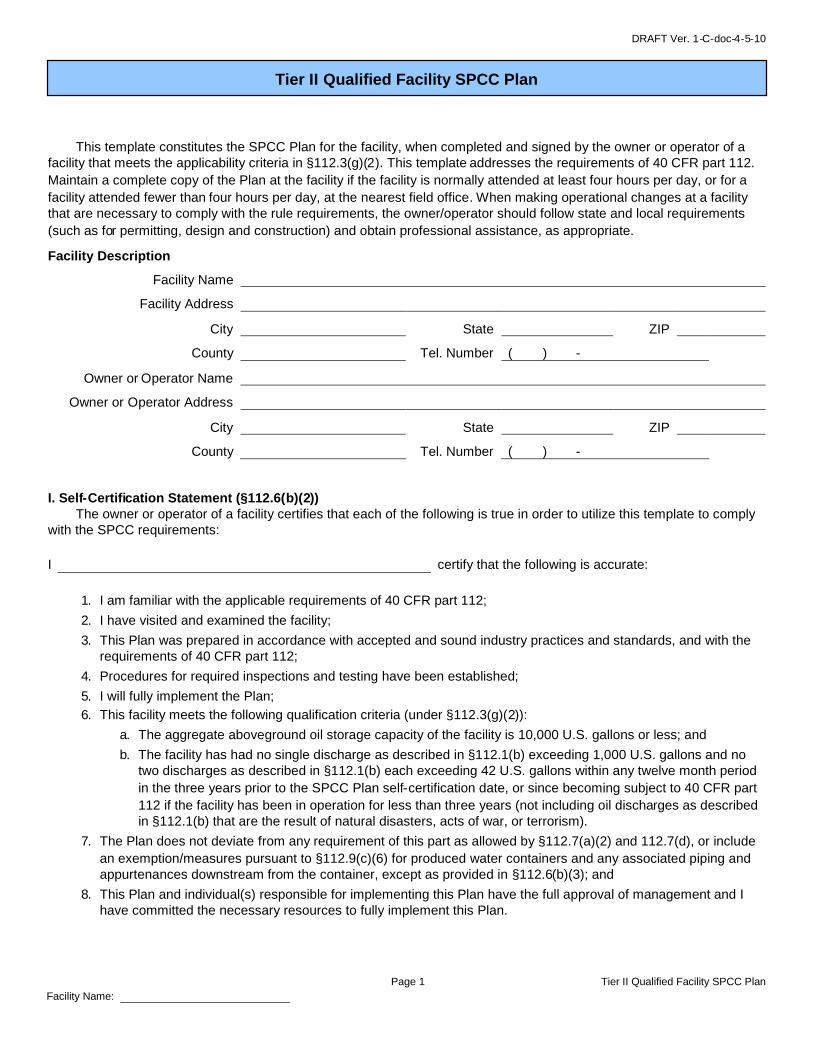
6. Contact List (§112.7(a)(3)(vi)):Table G-7 Contact List
Contact Organization / Person Telephone NumberNational Response Center (NRC) 1-800-424-8802Cleanup Contractor(s)
Key Facility Personnel
Office:Designated Person Accountable for Discharge Prevention:
Emergency:
Office:
Emergency:
Office:
Emergency:
Office:
Emergency:
California Emergency Management Agency – State WarningCenter 1-800-852-7550
Other State, Federal, and Local Agencies
Unified Program Agency
Local Fire Department
Local Police Department
Hospital
Other Contact References (e.g., downstream water intakesor neighboring facilities)
Facility Name:

DRAFT Ver. 1-C-doc-4-5-10
Page 8 Tier II Qualified Facility SPCC Plan
7. NRC Notification Procedure (§112.7(a)(4)):Table G-8 NRC Notification Procedure
In the event of a discharge of oil to navigable waters or adjoining shorelines, the following information identifiedin Attachment 4 will be provided to the National Response Center immediately following identification of adischarge to navigable waters or adjoining shorelinesa [See Discharge Notification Form in Attachment 4]:[§112.7(a)(4)]
The exact address or location and phonenumber of the facility;
Date and time of the discharge; Type of material discharged; Estimate of the total quantity discharged; Estimate of the quantity discharged to navigable
waters; Source of the discharge;
Description of all affected media; Cause of the discharge; Any damages or injuries caused by the discharge; Actions being used to stop, remove, and mitigate the
effects of the discharge; Whether an evacuation may be needed; and Names of individuals and/or organizations who have
also been contacted.
a Additional California release reporting requirements apply (HSC 25507(a) and 19 CCR 2703) including theimmediate reporting of releases and threatened releases posing a significant present or potential hazard to humanhealth and safety, property of the environment. In addition, HSC 25270.8 requires reporting of releases from a tankfacility of > 42 gallons of petroleum into state waters (or where they may pass into state waters). In addition to NRCreporting, the above releases must be immediately reported to the California Emergency Management Agency, theUPA and (if necessary) 911.
8. SPCC Spill Reporting Requirements (Report within 60 days) (§112.4):
Submit information to the US EPA Regional Administrator (RA) and the appropriate agency or agencies in charge of oilpollution control activities in the State b in which the facility is located within 60 days from one of the following dischargeevents:
A single discharge of more than 1,000 U.S. gallons of oil to navigable waters or adjoining shorelines or
Two discharges to navigable waters or adjoining shorelines each more than 42 U.S. gallons of oiloccurring within any twelve month period
b This includes the California Emergency Management Agency, Regional Water Quality Control Board, and the UPA.
Facility Name:
You must submit the following information to the RA:
(1) Name of the facility;(2) Your name;(3) Location of the facility;(4) Maximum storage or handling capacity of the facility and normal daily throughput;(5) Corrective action and countermeasures you have taken, including a description of
equipment repairs and replacements;(6) An adequate description of the facility, including maps, flow diagrams, and topographical
maps, as necessary;(7) The cause of the reportable discharge, including a failure analysis of the system or
subsystem in which the failure occurred; and(8) Additional preventive measures you have taken or contemplated to minimize the
possibility of recurrence(9) Such other information as the Regional Administrator may reasonably require pertinent
to the Plan or discharge

DRAFT Ver. 1-C-doc-4-5-10
Page 9 Tier II Qualified Facility SPCC Plan
9. Containers with Potential for an Oil Discharge (§112.7(b)):Table G-9 below identifies the tanks and containers at the facility with the potential for an oil discharge; the mode of failure; rate of flow; the flow direction and potential quantity of thedischarge; and the secondary containment method and containment capacity that is provided. Use additional pages if necessary.
Table G-9 Containers with Potential for an Oil Discharge
Area or ID Code (fromTables G-2 and G-3) Type of failure (discharge scenario)
Potentialdischargevolume
(gallons)
Flow rate(gal per
minute orother)
Direction offlow for
uncontaineddischarge
Secondary containmentmethoda
Secondarycontainment
capacity(gallons)
Bulk Storage Containers and Mobile/Portable Containersb
Oil-filled Operational Equipment (e.g., hydraulic equipment, transformers)c
Piping, Valves, etc.
Product Transfer Areas (location where oil is loaded to or from a container, pipe or other piece of equipment.)
Other Oil-Handling Areas or Oil-Filled Equipment (e.g. flow-through process vessels at an oil production facility)
a Use one of the following methods of secondary containment or its equivalent: (1) Dikes, berms, or retaining walls sufficiently impervious to contain oil; (2) Curbing; (3) Culverting,gutters, or other drainage systems; (4) Weirs, booms, or other barriers; (5) Spill diversion ponds; (6) Retention ponds; or (7) Sorbent materials.b For storage tanks and bulk storage containers, the secondary containment capacity must be at least the capacity of the largest container plus additional capacity to contain rainfallor other precipitation.c For oil-filled operational equipment: Document in the table above if alternative measures to secondary containment (as described in §112.7(k)) are implemented at the facility.
Facility Name:

DRAFT Ver. 1-C-doc-4-5-10
Page 10 Tier II Qualified Facility SPCC Plan
10. Containment or Diversionary Structures or Equipment to Prevent Oil Discharge (§112.7(c)):
Table G-10 Containment and/or Diversionary Structures or EquipmentAppropriate secondary containment and/or diversionary structures or equipmenta is provided for all oilhandling containers, equipment, and transfer areas to prevent a discharge to navigable waters oradjoining shorelinesb. The entire secondary containment system, including walls and floor, is capable ofcontaining oil and is constructed so that any discharge from a primary containment system, such as a tankor pipe, will not escape the containment system before cleanup occurs. [§112.7(c)]
a Use one of the following methods of secondary containment or its equivalent: (1) Dikes, berms, or retaining walls sufficientlyimpervious to contain oil; (2) Curbing; (3) Culverting, gutters, or other drainage systems; (4) Weirs, booms, or other barriers; (5) Spilldiversion ponds; (6) Retention ponds; or (7) Sorbent materials.
Except as noted below in footnote b for bulk storage containers and tanks (and loading/unloading racks), containment may be active orpassive in design or operation, and the containment method, design, and capacity need only address the typical failure mode, and themost likely quantity of oil that would be discharged.b Secondary containment for bulk storage containers and tanks must meet additional criteria (40 CFR 112.8(c) for stationary bulktanks/containers and 40 CFR 112.8(c)(11) for portable tanks/containers (see Section A of this Plan). Secondary containment for tanktruck/rail car loading or unloading racks must meet the criteria in 40 CFR 112.7(h)(1) (see Table G-15 of this Plan).
11. Containment Impracticability (§112.7(d)):
Table G-11 Determination of Impracticability and Provision of Alternative Measures N/A
This facility has determined that the installation of containment structures or pieces of equipmentrequired by/listed in §§112.7(c) and 112.7(h)(1), and §§112.8(c)(2), 112.8(c)(11), 112.9(c)(2),112.10(c), 112.12(c)(2), and 112.12(c)(11) to prevent a discharge as described in §112.1(b)a is notpracticable. For bulk storage containers, the facility will conduct both periodic integrity testing of thecontainers and periodic integrity and leak testing of the valves and piping; and, unless a FacilityResponse Plan has been submitted to US EPA under §112.20, attached to this plan is an oil spillcontingency plan following the provisions of 40 CFR part 109, and a written commitment of manpower,equipment, and materials required to expeditiously control and remove any quantity of oil dischargedthat may be harmful. [§112.7(d)]
The determination that secondary containment is impracticable and provisions in lieu of secondarycontainment have been reviewed and certified in writing by a Professional Engineer. The PE review andcertification must be included with this Plan. [§§112.6(b)(3)(ii) and 112.7(d)]
The following is a clear explanation of why such containment structures or measures are not practicable:
a A “discharge as described in §112.1(b)” generally means a discharge of oil in harmful quantities to a navigable water of the UnitesStates. A harmful quantity is the amount of oil which could cause a sheen upon the water, create an emulsion, or deposit a sludgeupon the shoreline. ‘Navigable waters of the United States” may include storm drain systems and culverts.
Facility Name:

DRAFT Ver. 1-C-doc-4-5-10
Page 11 Tier II Qualified Facility SPCC Plan
12. Inspections, Testing, and Recordkeeping (§§112.7(e), 112.8(c)(6) and (d)(4), 112.9(c)(3), 112.12(c)(6)and (d)(4)):
Table G-12 Inspections, Testing, and RecordkeepingInspections, tests, and records are conducted in accordance with written procedures developed for the facility.[§112.7(e)]
Inspections and tests are signed by the appropriate supervisor or inspector. [§112.7(e)]
An inspection and/or testing program is implemented for all aboveground bulk storage containers and piping atthis facility. [§§112.8(c)(6) and (d)(4), 112.9(c)(3), 112.12(c)(6) and (d)(4)]
The following is a description of the inspection and/or testing program (e.g. description, summary or list of the writteninspection/testing procedures in place; reference to the industry standard utilized; the scope, frequency, method ofinspections or tests; and the qualifications of the person conducting the inspection) for all aboveground bulk storagecontainers and piping at this facility:
Facility Name:

DRAFT Ver. 1-C-doc-4-5-10
Page 12 Tier II Qualified Facility SPCC Plan
13. Personnel Training (§112.7(f)):
Table G-13 Personnel, Training, and Discharge Prevention Procedures [§112.7(f)]Oil-handling personnel are trained in the operation and maintenance of equipment to prevent discharges;discharge procedure protocols; applicable pollution control laws, rules, and regulations; general facilityoperations; and, the contents of the facility SPCC Plan. [§112.7(f)][See Oil-handling Personnel Training and Briefing Log in Attachment 3.4]
A person who reports to facility management is designated and accountable for discharge prevention.[§112.7(f)]
Name/Title:
Discharge prevention briefings are conducted for oil-handling personnel annually to assure adequateunderstanding of the SPCC Plan for that facility. Such briefings highlight and describe past reportabledischarges or failures, malfunctioning components, and any recently developed precautionary measures.[§112.7(f)][See Oil-handling Personnel Training and Briefing Log in Attachment 3.4]
14. Security (excluding oil production facilities) (§112.7(g):Table G-14 Implementation and Description of Security Measures
Security measures are implemented at this facility to prevent unauthorized access to oil handling, processing,and storage area.
The following is a description of how the facility secures and controls access to the oil handling, processing and storageareas; secure master flow and drain valves; prevents unauthorized access to starter controls on oil pumps; secures out-of-service and loading/unloading connections of oil pipelines; and addresses the appropriateness of security lighting toboth prevent acts of vandalism and assist in the discovery of oil discharges:
Facility Name:

DRAFT Ver. 1-C-doc-4-5-10
15. Facility Tank Car and Tank Truck Loading/Unloading Rack (excluding offshore facilities, farms,and oil production facilities) (§112.7(h)):
Table G-15 Loading/Unloading Racks N/A
Where loading/unloading rack drainage does not flow into a catchment basin or treatment facilitydesigned to handle discharges, the facility will use a quick drainage system for tank car or tank truckloading/unloading racks. The facility will design all containment systems to hold at least the maximumcapacity of a tank car or tank truck loaded or unloaded at the facility.
The facility will provide an interlocked warning light or physical barrier system, warning signs, wheelchocks or vehicle brake interlock system in the area adjacent to a loading/unloading rack, to preventvehicles from departing before complete disconnection of flexible or fixed oil transfer lines.
Prior to filling and departure of any tank car or tank truck at the facility, employees will closely inspectfor discharges at the lower most drain and all outlets of such vehicles, and if necessary, ensure thatthey are tightened, adjusted, or replaced to prevent liquid discharge while in transit.
16. Field Constructed Aboveground Containers) (§112.7(i)):
Table G-16 Field Constructed Aboveground Containers N/A
If a field-constructed aboveground container at the facility undergoes a repair, alteration, reconstruction,or a change in service that might affect the risk of a discharge or failure due to brittle fracture or othercatastrophe, or has discharged oil or failed due to brittle fracture failure or other catastrophe, the facilitywill evaluate the container for risk of discharge or failure due to brittle fracture or other catastrophe, andas necessary, take appropriate action.
17. Conformance with Other Applicable Requirements (§112.7(i)):
Table G-17 Conformance with Other Applicable State Rules or Regulations [§112.7(i)]In addition to the minimal prevention standards listed under this section, the following is a complete discussion ofconformance with any applicable more stringent State rules, regulations, and guidelines. [§112.7(i)]
* * * * *
Facility Name:Facility Name:
NOTE: Complete one of the following sections (A, B or C)
Page 13 Tier II Qualified Facility SPCC Plan
as appropriate for the facility type.

DRAFT Ver. 1-C-doc-4-5-10
Page 14 Tier II Qualified Facility SPCC Plan
The owner or operator must meet the general rule requirements as well as requirements under this section. Note that not all provisionsmay be applicable to all owners/operators. For example, a facility may not maintain completely buried metallic storage tanks installedafter January 10, 1974, and thus would not have to abide by requirements in §§112.8(c)(4) and 112.12(c)(4), listed below. In caseswhere a provision is not applicable, write “N/A”.
Table G-18 General Rule Requirements for Onshore Facilities N/A
Facility Drainage RequirementsDrainage from diked storage areas is restrained by valves to prevent a discharge into the drainagesystem or facility effluent treatment system, except where facility systems are designed to control suchdischarge. Diked areas may be emptied by pumps or ejectors that must be manually activated afterinspecting the condition of the accumulation to ensure no oil will be discharged. [§§112.8(b)(1) and112.12(b)(1)]
Valves of manual, open-and-closed design are used for the drainage of diked areas. [§§112.8(b)(2) and112.12(b)(2)]
Facility drainage systems from undiked areas with a potential for a discharge are designed to flow intoponds, lagoons, or catchment basins to retain oil or return it to the facility. Catchment basins are notlocated in areas subject to periodic flooding. [§112.8(b)(3) and 112.12(b)(3)]
If facility drainage is not engineered as in (b)(3) above, the facility will equip the final discharge of allditches inside the facility with a diversion system that would, in the event of an uncontrolled discharge,retain oil in the facility. [§112.8(b)(4) and 112.12(b)(4)]
Where drainage waters are treated in more than one treatment unit and such treatment is continuous,and pump transfer is needed, two “lift” pumps are provided and at least one of the pumps is permanentlyinstalled. Whatever techniques are used, facility drainage systems have been engineered to prevent adischarge as described in §112.1(b) in case there is an equipment failure or human error at the facility.[§112.8(b)(5) and 112.12(b)(5)]
Bulk Storage Container RequirementsThe containers at the facility are compatible with materials stored and conditions of storage such aspressure and temperature. [§§112.8(c)(1) and 112.12(c)(1)]
All facility bulk storage tank installations (including mobile or portable oil storage containers) provide asecondary means of containment for the entire capacity of the largest single container and sufficientfreeboard to contain precipitation. Diked areas are sufficiently impervious to contain discharged oil.[§112.8(c)(2) & (c)(11)]
An alternative containment system has been provided consisting of a drainage trench enclosure arrangedso that any discharge will terminate and be safely confined in a facility catchment basin or holding pond.[§112.8(c)(2)]
Mobile refuelers and/or other non-transportation related tank trucks are provided with generalcontainment or other diversionary structures or equipment meeting §112.7(c) (see Table G-10).[§112.8(c)(11)]
Mobile or portable oil storage containers are positioned to prevent a discharge as described in §112.1(b).[§112.8(c)(11)]
Diked Area DrainageIf uncontaminated rainwater from diked areas drains into a storm drain or open watercourse (bypassingany facility effluent treatment system) the following procedures will be implemented at the facility:[§§112.8(c)(3)(i – iv) and 112.12(c)(3)(i – iv)]
Bypass valve is normally sealed closed Retained rainwater is inspected to ensure that its presence will not cause a discharge to
navigable waters or adjoining shorelines Bypass valve is opened and resealed following drainage under responsible supervision Adequate records of drainage are kept [See Dike Drainage Log in Attachment 3.3]
Facility Name:
A. Onshore Facilities (excluding production) (§§112.8(b) through (d), 112.12(b) through (d)):

DRAFT Ver. 1-C-doc-4-5-10
Page 15 Tier II Qualified Facility SPCC Plan
Table G-18 General Rule Requirements for Onshore Facilities N/A
Buried Tanks
For completely buried metallic tanks installed on or after January 10, 1974 at this facility: [§112.8(c)(4)and 112.12(c)(4)]
Tanks have corrosion protection with coatings or cathodic protection compatible with local soilconditions.
Regular leak testing is conducted.
For partially buried or bunkered metallic tanks [§112.8(c)(5) and §112.12(c)(5)]: Tanks have corrosion protection with coatings or cathodic protection compatible with local soil
conditions.
Bulk Container Inspection and TestingEach aboveground bulk container is tested or inspected for integrity on a regular schedule and whenevermaterial repairs are made. Records of testing and inspection are kept – including comparison records.Scope and frequency of the inspections and inspector qualifications are in accordance with industrystandards. [See Inspection Log and Schedule and Bulk Storage Container Inspection Schedule inAttachments 3.1 and 3.2] [§112.8(c)(6) and §112.12(c)(6)(i)]
Outsides of bulk storage containers are frequently inspected for signs of deterioration, discharges, oraccumulation of oil inside diked areas. Container supports and foundations are regularly inspected. [SeeInspection Log and Schedule in Attachment 3.1] [§§112.8(c)(6) and 112.12(c)(6)]
For bulk storage containers that are subject to 21 CFR part 110 which are shop-fabricated, constructed ofaustenitic stainless steel, elevated and have no external insulation, formal visual inspection is conductedon a regular schedule. Appropriate qualifications for personnel performing tests and inspections aredocumented. [See Inspection Log and Schedule and Bulk Storage Container Inspection Schedulein Attachments 3.1 and 3.2] [§112.12(c)(6)(ii)]
Internal Heating CoilsThe facility will control leakage through defective internal heating coils by monitoring the steam return andexhaust lines for contamination from internal heating coils that discharge into an open watercourse, orpassing the steam return or exhaust lines through a settling tank, skimmer, or other separation orretention system. [§112.8(c)(7)]
Overfill Prevention and Container EngineeringEach container installation has been engineered or updated in accordance with good engineering practiceto avoid discharges. [§112.8(c)(8)]
For each bulk container or container installation, at least one of the following devices is provided:[§112.8(c)(8)(i – iv))]
High liquid level alarms with an audible or visual signal at a constantly attended operation orsurveillance station. In smaller facilities an audible air vent may suffice.
High liquid level pump cutoff devices set to stop flow at a predetermined container content level. Direct audible or code signal communication between the container gauger and the pumping
station. A fast response system for determining the liquid level of each bulk storage container such as
digital computers, telepulse, or direct vision gauges. If this alternative is used, the facility willensure a person be present to monitor gauges and the overall filling of bulk storage containers.
Liquid level sensing devices are regularly tested to ensure proper operation [See Inspection Log andSchedule in Attachment 3.1]. [§112.8(c)(8)(v)]
Effluent Treatment FacilitiesThe facility observes on-site effluent treatment facilities frequently enough to detect possible systemupsets that could cause a discharge as described in §112.1(b). [§112.8(c)(9)]
Visible Discharge CorrectionVisible discharges which result in a loss of oil from the container, including but not limited to seams,gaskets, piping, pumps, valves, rivets, and bolts are promptly corrected and oil in diked areas is promptlyremoved. [§§112.8(c)(10) and 112.12(c)(10)]

DRAFT Ver. 1-C-doc-4-5-10
Page 16 Tier II Qualified Facility SPCC Plan
Table G-18 General Rule Requirements for Onshore Facilities N/A
Facility Transfer Operations and PipingBuried piping that is installed or replaced on or after August 16, 2002 is provided with a protectivewrapping and coating. Such buried piping installations is either cathodically protected or otherwisesatisfies the corrosion protection standards for piping in 40 CFR part 280 of this chapter or a Stateprogram approved under 40 CFR part 281 (such as California HSC Chapter 6.7 and 23 CCRrequirements for underground storage tank systems). [§§112.8(d)(1) and 112.12(d)(1)]
If a section of buried line is exposed for any reason, the facility will carefully inspect it for deterioration. Ifcorrosion damage is found, the facility will undertake additional examination and corrective action asindicated by the magnitude of the damage. [See Inspection Log and Schedule in Attachment 3.1][§§112.8(d)(1) and 112.12(d)(1)]
Terminal connections at transfer points are capped or blank-flanged and marked as to origin when pipingis not in service or is in standby service for an extended time. [§§112.8(d)(2) and 112.12(d)(2)]
Pipe supports are properly designed to minimize abrasion and corrosion and allow for expansion andcontraction. [§§112.8(d)(3) and 112.12(d)(3)]
Aboveground valves, piping, and appurtenances such as flange joints, expansion joints, valve glands andbodies, catch pans, pipeline supports, locking of valves, and metal surfaces are inspected regularly. [SeeInspection Log and Schedule in Attachment 3.1] [§§112.8(d)(4) and 112.12(d)(4)]
Integrity and leak testing are conducted on buried piping at the time of installation, modification,construction, relocation, or replacement. [See Inspection Log and Schedule in Attachment 3.1][§§112.8(d)(4) and 112.12(d)(4)]
All vehicles entering the facility are warned to be sure that no vehicle will endanger aboveground pipingor other oil transfer operations. [§§112.8(d)(5) and 112.12(d)(5)]
Facility Name:

DRAFT Ver. 1-C-doc-4-5-10
Page 17 Tier II Qualified Facility SPCC Plan
The owner or operator must meet the general rule requirements as well as the requirements under this section. Note that not allprovisions may be applicable to all owners/operators. In cases where a provision is not applicable, write “N/A”.
Table G-19 General Rule Requirements for Onshore Oil Production Facilities N/AAt tank batteries, separation and treating areas, drainage is closed and sealed except when draininguncontaminated rainwater. Accumulated oil on the rainwater is returned to storage or disposed of inaccordance with legally approved methods. [§112.9(b)(1)]Prior to drainage, diked areas are inspected and [§112.9(b)(1)]:
Retained rainwater is inspected to ensure that its presence will not cause a discharge tonavigable waters
Bypass valve is opened and resealed under responsible supervision Adequate records of drainage are kept [See Dike Drainage Log in Attachment 3.3]
Field drainage systems and oil traps, sumps, or skimmers are inspected at regularly scheduled intervalsfor oil, and accumulations of oil are promptly removed [See Inspection Log and Schedule inAttachment 3.1] [§112.9(b)(2)]The containers used at this facility are compatible with materials stored and conditions of storage.[§112.9(c)(1)]All tank battery, separation, and treating facility installations (except for flow-through process vessels) areconstructed with a capacity to hold the largest single container plus additional capacity to contain rainfall.Drainage from undiked areas is safely confined in a catchment basin or holding pond. [§112.9(c)(2)]Except for flow-through process vessels, containers that are on or above the surface of the ground,including foundations and supports, are visually inspected for deterioration and maintenance needs on aregular schedule. [See Inspection Log and Schedule in Attachment 3.1] [§112.9(c)(3)]New and old tank batteries at this facility are engineered/updated in accordance with good engineeringpractices to prevent discharges including at least one of the following:
i. adequate container capacity to prevent overfill if regular pumping/gauging is delayed;ii. overflow equalizing lines between containers so that a full container can overflow to an adjacent
container;iii. vacuum protection to prevent container collapse; oriv. high level sensors to generate and transmit an alarm to the computer where the facility is subject to a
computer production control system. [§112.9(c)(4)]Flow-through process vessels and associated components are:
Are constructed with a capacity to hold the largest single container plus additional capacity tocontain rainfall. Drainage from undiked areas is safely confined in a catchment basin or holdingpond; [§112.9(c)(2)] and
That are on or above the surface of the ground, including foundations and supports, are visuallyinspected for deterioration and maintenance needs on a regular schedule. [See Inspection Logand Schedule in Attachment 3.1] [§112.9(c)(3)]
Or Visually inspected and/or tested periodically and on a regular schedule for leaks, corrosion, or
other conditions that could lead to a discharge to navigable waters; and Corrective action or repairs are applied to flow-through process vessels and any associated
components as indicated by regularly scheduled visual inspections, tests, or evidence of an oildischarge; and
Any accumulations of oil discharges associated with flow-through process vessels are promptlyremoved; and
Flow-through process vessels are provided with a secondary means of containment for the entirecapacity of the largest single container and sufficient freeboard to contain precipitation within sixmonths of a discharge from flow-through process vessels of more than 1,000 U.S. gallons of oil ina single discharge as described in §112.1(b), or a discharge more than 42 U.S. gallons of oil ineach of two discharges as described in §112.1(b) within any twelve month period. [§112.9(c)(5)](Leave blank until such time that this provision is applicable.)
Facility Name:
B. Onshore Oil Production Facilities (excluding drilling and workover facilities) (§112.9(b), (c), and(d)):

DRAFT Ver. 1-C-doc-4-5-10
Page 18 Tier II Qualified Facility SPCC Plan
Table G-19 General Rule Requirements for Onshore Oil Production Facilities N/AAll aboveground valves and piping associated with transfer operations are inspected periodically andupon a regular schedule. The general condition of flange joints, valve glands and bodies, drip pans, pipesupports, pumping well polish rod stuffing boxes, bleeder and gauge valves, and other such items areincluded in the inspection. [See Inspection Log and Schedule in Attachment 3.1] [§112.9(d)(1)]An oil spill contingency plan and written commitment of resources are provided for flowlines and intra-facility gathering lines [See Oil Spill Contingency Plan and Checklist in Attachment 2 and InspectionLog and Schedule in Attachment 3.1] [§112.9(d)(3)]orAppropriate secondary containment and/or diversionary structures or equipment is provided for flowlinesand intra-facility gathering lines to prevent a discharge to navigable waters or adjoining shorelines. Theentire secondary containment system, including walls and floor, is capable of containing oil and isconstructed so that any discharge from the pipe, will not escape the containment system before cleanupoccurs.A flowline/intra-facility gathering line maintenance program to prevent discharges from each flowline hasbeen established at this facility. The maintenance program addresses each of the following:
Flowlines and intra-facility gathering lines and associated valves and equipment are compatiblewith the type of production fluids, their potential corrosivity, volume, and pressure, and otherconditions expected in the operational environment;
Flowlines, intra-facility gathering lines and associated appurtenances are visually inspectedand/or tested on a periodic and regular schedule for leaks, oil discharges, corrosion, or otherconditions that could lead to a discharge as described in §112.1(b). The frequency and type oftesting allows for the implementation of a contingency plan as described under part 109 of thischapter.
Corrective action and repairs to any flowlines and intra-facility gathering lines and associatedappurtenances as indicated by regularly scheduled visual inspections, tests, or evidence of adischarge.
Accumulations of oil discharges associated with flowlines, intra-facility gathering lines, andassociated appurtenances are promptly removed. [§112.9(d)(4)]
The following is a description of the flowline/intra-facility gathering line maintenance program implemented at thisfacility:
NEED TO ADD SECTION ITEMS FOR 112.9(c)(6)(i - v) and 112.9(d)(2) and (5).
Facility Name:

DRAFT Ver. 1-C-doc-4-5-10
Page 19 Tier II Qualified Facility SPCC Plan
The owner or operator must meet the general rule requirements as well as the requirements under this section.
Table G-20 General Rule Requirements for Onshore Oil Drilling and Workover FacilitiesMobile drilling or worker equipment is positioned or located to prevent discharge as described in §112.1(b).[§112.10(b)]Catchment basins or diversion structures are provided to intercept and contain discharges of fuel, crude oil, oroily drilling fluids. [§112.10(c)]A blowout prevention (BOP) assembly and well control system was installed before drilling below any casingstring or during workover operations. [§112.10(d)]The BOP assembly and well control system is capable of controlling any well-head pressure that may beencountered while the BOP assembly and well control system are on the well. [§112.10(d)]
Facility Name:
C. Onshore Oil Drilling and Workover Facilities (§112.10(b), (c) and (d)):

DRAFT Ver. 1-C-doc-4-5-10
Page 20 Tier II Qualified Facility SPCC Plan
ATTACHMENT 1 – Five Year Review and Technical Amendment Logs
I have completed a review and evaluation of the SPCC Plan for this facility, and will/will not amend this Plan as a result.
Table G-21 Review and Evaluation of SPCC Plan for FacilityPlan AmendmentReview Date
Will Amend Will Not AmendName, title and signature of person authorized to reviewthis Plan
Description of changes/amendments:
Description of changes/amendments:
Description of changes/amendments:
Description of changes/amendments:
Description of changes/amendments:
Facility Name:
ATTACHMENT 1.1 – Five Year Review Log

DRAFT Ver. 1-C-doc-4-5-10
ATTACHMENT 1.2 – Technical Amendment Log
Any technical amendments to this Plan will be re-certified in accordance with Section I of this Plan template.
Table G-22 Description and Certification of Technical AmendmentsReview orAmendmentDate
Description of Technical Amendment Name and signature of person certifying thistechnical amendment
Page 21 Tier II Qualified Facility SPCC PlanFacility Name:

DRAFT Ver. 1-C-doc-4-5-10
A
CO
a
F
Page 22 Tier II Qualified Facility SPCC Plann oil spill contingency plan meeting the requirements of 40 CFR part 109 and a written commitment of resources is required for:
Any bulk container, tank or area where secondary containment has been determined to be impracticable (40 CFR part112.7(d)
Qualified oil-filled operational equipment which has no secondary containment (40 CFR part 112.7(k)
Flowlines and intra-facility gathering lines at oil production facilities
An oil spill contingency plan meeting the provisions of 40 CFR part 109, as described below, and a writtencommitment of manpower, equipment and materials required to expeditiously control and remove any quantityof oil discharged that may be harmful is attached to this Plan.omplete the checklist below to verify that the necessary operations outlined in 40 CFR part 109 - Criteria for State, Local and Regionalil Removal Contingency Plans - have been included.
Table G-23 Checklist of Development and Implementation Criteria for State, Local and Regional Oil RemovalContingency Plans (§109.5)a
(a) Definition of the authorities, responsibilities and duties of all persons, organizations or agencies which areto be involved in planning or directing oil removal operations.
(b) Establishment of notification procedures for the purpose of early detection and timely notification of an oildischarge including:
(1) The identification of critical water use areas to facilitate the reporting of and response to oil discharges.(2) A current list of names, telephone numbers and addresses of the responsible persons (with alternates)
and organizations to be notified when an oil discharge is discovered.(3) Provisions for access to a reliable communications system for timely notification of an oil discharge,
and the capability of interconnection with the communications systems established under related oilremoval contingency plans, particularly State and National plans (e.g., NCP).
(4) An established, prearranged procedure for requesting assistance during a major disaster or when thesituation exceeds the response capability of the State, local or regional authority.
(c) Provisions to assure that full resource capability is known and can be committed during an oil dischargesituation including:(1) The identification and inventory of applicable equipment, materials and supplies which are available
locally and regionally.(2) An estimate of the equipment, materials and supplies which would be required to remove the maximum
oil discharge to be anticipated.(3) Development of agreements and arrangements in advance of an oil discharge for the acquisition of
equipment, materials and supplies to be used in responding to such a discharge.
(d) Provisions for well defined and specific actions to be taken after discovery and notification of an oildischarge including:
(1) Specification of an oil discharge response operating team consisting of trained, prepared and availableoperating personnel.
(2) Predesignation of a properly qualified oil discharge response coordinator who is charged with theresponsibility and delegated commensurate authority for directing and coordinating response operationsand who knows how to request assistance from Federal authorities operating under existing nationaland regional contingency plans.
(3) A preplanned location for an oil discharge response operations center and a reliable communicationssystem for directing the coordinated overall response operations.
(4) Provisions for varying degrees of response effort depending on the severity of the oil discharge.(5) Specification of the order of priority in which the various water uses are to be protected where more
than one water use may be adversely affected as a result of an oil discharge and where responseoperations may not be adequate to protect all uses.
(6) Specific and well defined procedures to facilitate recovery of damages and enforcement measures asprovided for by State and local statutes and ordinances.
The contingency plan must be consistent with all applicable state and local plans, Area Contingency Plans, and the NationalContingency Plan (NCP)
acility Name:
ATTACHMENT 2 – Oil Spill Contingency Plan and Checklist

V DRAFT Ver. 1-C-doc-4-5-10
Page 23 Tier II Qualified Facility SPCC Plan
ATTACHMENT 3 – Inspections, Dike Drainage and Personnel Training Logs
Table G-24 Inspection & Testing Log and ScheduleThis log is intended to document compliance with §§112.7(e), 112.8(c)(6), 112.8(c)(8), 112.8(c)(9), 112.8(d)(1), 112.8(d)(4), 112.9(b)(2), 112.9(c)(3),
112.9(d)(1), 112.9(d)(4), 112.12.(c)(6), and 112.12(d)(4), as applicable.
Date ofInspection
Container /Piping /Equipment
Describe Scope(or cite IndustryStandard)
Observations Name/ Signature of InspectorRecords
maintainedseparately a
a Indicate in the table above if records of facility inspections are maintained separately at this facility.
Facility Name:
ATTACHMENT 3.1 – Inspection Log and Schedule

DRAFT Ver. 1-C-doc-4-5-10
Page 24 Tier II Qualified Facility SPCC Plan
To comply with integrity inspection requirement for bulk storage containers, inspect/test each shop-built aboveground bulk storagecontainer on a regular schedule in accordance with a recognized container inspection standard based on the minimum requirements inthe following table.
Table G-25 Bulk Storage Container Inspection Schedule
Container Size and Design Specification Inspection requirement
Portable containers (including drums, totes, and intermodalbulk containers (IBC))
Visually inspect monthly for signs of deterioration,discharges or accumulation of oil inside diked areas
55 to 1,100 gallons with sized secondary containment
1,101 to 5,000 gallons with sized secondary containment and ameans of leak detectiona
Visually inspect monthly for signs of deterioration,discharges or accumulation of oil inside diked areasplus any annual inspection elements per industryinspection standardsb
1,101 to 5,000 gallons with sized secondary containment andno method of leak detectiona
Visually inspect monthly for signs of deterioration,discharges or accumulation of oil inside diked areas,plus any annual inspection elements and otherspecific integrity tests that may be required perindustry inspection standardsb
Depending upon the industry standard used,referenced or considered, additional integrity testingmay include an integrity test, leak test or inspectionof the tank exterior and/or interior by an industrystandard-certified inspector every 2, 5 or 10 years.
5,001 to 10,000 gallons with sized secondary containment anda means of leak detectiona, c
Visually inspect monthly for signs of deterioration,discharges or accumulation of oil inside diked areasplus any annual inspection elements and otherspecific integrity tests per industry inspectionstandardsb.
Depending upon the industry standard used,referenced or considered, additional integrity testingmay include an integrity test or inspection of the tankexterior by an industry standard-certified inspectorevery 20 years.
5,001 to 10,000 gallons with sized secondary containment andno means of leak detectiona, c
Visually inspect monthly for signs of deterioration,discharges or accumulation of oil inside diked areasplus any annual inspection elements and otherspecific integrity tests per industry inspectionstandardsb.
Depending upon the industry standard used,referenced or considered, additional integrity testingmay include an integrity test, leak test or inspectionof the tank exterior and interior by an industrystandard-certified inspector every 1, 5, 10 or 15 yrs.
a Examples of leak detection include, but are not limited to, double-walled tanks, tanks within non-earthen secondary containmentstructures and elevated containers where a leak can be visually identified prior to any leaking entering the ground surface.b Industry standards for inspections and integrity testing may include the Steel Tank Institute “Standard for the inspection ofAboveground Storage Tanks – SP001”, 4th Edition, July 2006, or other relevant standards.c Facilities with storage tanks over 10,000 gallons oil storage capacity do not meet the criteria for a Tier II qualified facility.
Facility Name:
ATTACHMENT 3.2 – Bulk Storage Container Inspection Schedule – onshore facilities (excludingproduction):

DRAFT Ver. 1-C-doc-4-5-10
Page 25 Tier II Qualified Facility SPCC Plan
Table G-26 Dike Drainage Log
Date
Bypassvalve
sealedclosed
Rainwaterinspected to besure no oil (or
sheen) is visible
Open bypassvalve andreseal itfollowingdrainage
Drainageactivity
supervisedObservations Signature of Inspector
Facility Name:
ATTACHMENT 3.3 – Dike Drainage Log

DRAFT Ver. 1-C-doc-4-5-10
Page 26 Tier II Qualified Facility SPCC Plan
Table G-27 Oil-Handling Personnel Training and Briefing LogDate Description / Scope Attendees
Facility Name:
ATTACHMENT 3.4 – Oil-handling Personnel Training and Briefing Log

DRAFT Ver. 1-C-doc-4-5-10
Page 27 Tier II Qualified Facility SPCC Plan
In the event of a discharge of oil to navigable waters or adjoining shorelines, the following information will be provided to the NationalResponse Center [also see the notification information provided in Section 7 of the Plan]:
Table G-28 Information provided to the National Response Center in the Event of a DischargeDischarge/Discovery Date Time
Facility Name
Facility Location (Address/Lat-Long/Section Township Range)
Name of reporting individual Telephone #
Type of material discharged Estimated total quantitydischarged
Gallons/Barrels
Source of the discharge Media affected Soil
Water (specify)
Other (specify)
Actions taken
Damage or injuries Evacuation needed?No Yes (specify) No Yes (specify)
National Response Center 800-424-8802 Time
Cleanup contractor (Specify) Time
Facility personnel (Specify) Time
State Agency (Specify) Time
Organizations and individualscontacted
Other (Specify) Time
Facility Name:
ATTACHMENT 4 – Discharge Notification Form


![Model SPCC Plan - Maine · Web viewOil SPCC Plan Typical Retail Facility [city], Maine Revision 0 Prepared by SPCC Plan Engineering, Inc. _____ Street _____, Maine 04xxx Project No.](https://static.fdocuments.net/doc/165x107/5b0299d67f8b9a54578ff7e4/model-spcc-plan-viewoil-spcc-plan-typical-retail-facility-city-maine-revision.jpg)