APRV Analyzer - DFV Technologiedfv-technologie.com/pdf/comaprveng.pdf · - 3 - According to its...
16
dfv Technologie Z.A. Ravennes-les-Francs 2 avenue Henri Poincaré 59910 BONDUES FRANCE Tel : 33 (0) 3.20.69.02.85 Fax : 33 (0) 3.20.69.02.86 Email : [email protected] Site Web : www.dfv.fr APRV Analyzer
Transcript of APRV Analyzer - DFV Technologiedfv-technologie.com/pdf/comaprveng.pdf · - 3 - According to its...
dfv Technologie Z.A. Ravennes-les-Francs 2 avenue Henri Poincaré 59910 BONDUES FRANCE Tel : 33 (0) 3.20.69.02.85 Fax : 33 (0) 3.20.69.02.86 Email : [email protected] Site Web : www.dfv.fr
APRV Analyzer
- 2 -
GENERAL
APRV replaces two analyser/recorders: 1) APRV continuously records each mains network electrical parameter
(U,I,P,Q,S,Phase,Harmonics ...) with an integrating period adjustable between one minute and one hour.
2) APRV detects and records low frequency events (voltage drop, over-voltages, wave
distortion) with a sampling frequency of 6400 Hz.
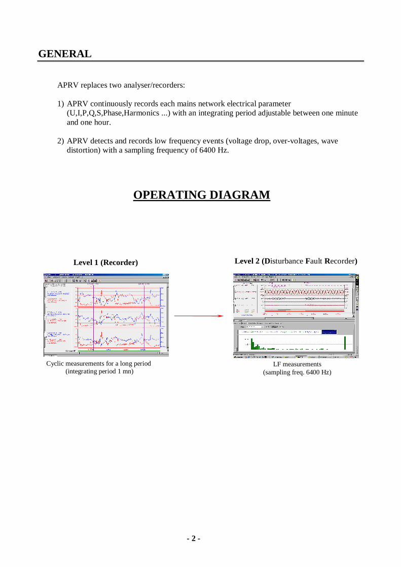
Cyclic measurements for a long period (integrating period 1 mn)
LF measurements (sampling freq. 6400 Hz)
OPERATING DIAGRAM
Level 1 (Recorder) Level 2 (Disturbance Fault Recorder)
- 3 -
According to its programming the APRV enables an electrical network to be monitored in real time disturbance mode.
Monitoring: – 2-phase or 3-phase networks ( 3 or 4 wires) Detection: - voltage drops - over-voltages - wave distortion Restoration: – RMS. voltages and currents – Active, reactive power – Cosine and tangent – Asymmetrical mode (3-phase networks) – Harmonic levels V and I by order (2 to 63), and transfer direction – Level of global distortion for V and I
Measurement storage is optimised to reduce the memory occupation as far as possible without affecting the measurement accuracy. Analysis of measurements is achieved: Locally - with the APRV (with a VGA screen, PC keyboard and external printer) - or with a compatible Personal Computer, this analysis is performed with all the 3-phase mains
network parameters, by means of APRWIN software. Remotely (Option) – by a compatible Personal Computer, by means of a modem connected to the switched network,
to a dedicated link or to a multiple point-to-point network During the data transfer or processing, APRV continues scanning and storage of measurements. APRV calculation capacity permits the RMS. value and the curve of the wave of 8 alternating channels (Voltage or current) to be monitored in real time, as well as the variation in state of 16 logical channels. It is possible to survey 16 analog channels and 32 logical channels by adding a second data acquisition card, an analog measuring unit and a logical channel unit
- 4 -
Triggering: The triggering and storage of measurements may be obtained: in "Manual mode"
– by hitting a keyboard key in "Automatic mode"
– by overrunning a max. or min. threshold of RMS. value on one of channels – by variation of signal amplitude in time (dv/dt or di/dt) – by overrunning a max. or min. threshold of rate on an harmonic order – by overrunning global rate threshold – by variation of state of one or more logical channels (AND function, OR function)
Threshold and duration alignments of each channel are completed by the user using the keyboard. In these 2 modes the APRV stores measurements with a pre-time adjustable from 20 to 200 ms, and a post-time adjustable from 400 ms to 4800 ms. If triggering occurs before the post-time end, the recording time is increased by the time of the post-time. The max. storage time is 5 seconds (40 seconds with the optional software ref. -PE-LOGDEM). Measurement storage: The storage of measurements is performed on the APRV compact flash Measurement processing: The processing of measurements is achieved :
- by APRV by means of the keyboard, screen and external printer. - with an IBM or compatible Personal Computer, measurement may be transferred by
means: - of CF card - of RS 232 link, locally or remotely on the switched network.

- 5 -
APRV Description The APRV is made up of two main parts: 1) A measuring and detection module This module is based on a high-capacity signal processor, DSP by Motorola. DSP performances permit a real-time measurement and detection of overrunning the programmed thresholds onto 8 analog and 16 numerical channels (or 16 analog and 32 logical channels). Measured signals are sampled at an average frequency of 6400 Hz. An automatic synchronisation system enables adjustment of the sampling frequency to obtain 128 samples per period (input frequency of 50 Hz). All channels are simultaneously sampled by the use of blocker-samplers. Each input signal period is fractioned into a series of 128 complex numbers (Fast Fourier Transform) characterising the module and the phase of each component of the signal up to the 63rd harmonic. This mode of representation greatly facilitates all future numerical processing:
- RMS. value calculation - Calculation of active, reactive power and apparent of the cosine and tangent phase taking into
account an input voltage and an input current. - Calculation of direct, reverse and zero-sequence voltage taking into account a 3-phase system.
With this mode of representation, it is possible to restore the original signal (visualisation). Each sampled period is analysed in real-time to detect a programmed event. In case of detection the DSP transfers the set of measurements corresponding to the element detected into the host system memory (second part) and informs it for immediate acknowledgement and storage. 2) Host module for dialog and storage This module drives the detection module. It is constituted of a CPU board micro-processor with: - 16 Mbytes of RAM – 1 x 256Mo Compact Flash Card – 1 x parallel output for external printer – 3 x serial outputs (RS232, modem, radio clock ) – 1 x colour LCD screen - 1 Ethernet 10baseT plug The operating system used is a multi-task system, called SDOS. This system enables the best management of the host processor activity, by modifying the priority of processing tasks to be accomplished according to detected events.
- 6 -
All software is stored on the hard disk to simplify any possible modification or improvement. The software which manages the DSP is also stored on the hard disk and automatically loaded in its memory during the initialisation. Host module functions are: – Detection module programming: When measurement begins, the software detection module is loaded in the DSP module memory, and also the set of overrunning parameters requested by the operator. These overrunning parameters are introduced in the APRV by means of an interactive software. – Storage of events detected by the DSP: A priority task, advised by the detection module that an event has to be stored, processes the raw data, compacts and stores them on the hard disk, which decreases the space used and increases the storage capacity. Management of memory is optimised to permit a detection of consecutive events without APRV saturation. The maximum duration of an event is 5 seconds. An optional module enables events to be processed within 40 seconds ( E.g. motor starting) All measurement files are available for displaying and on-site processing.
- 7 -
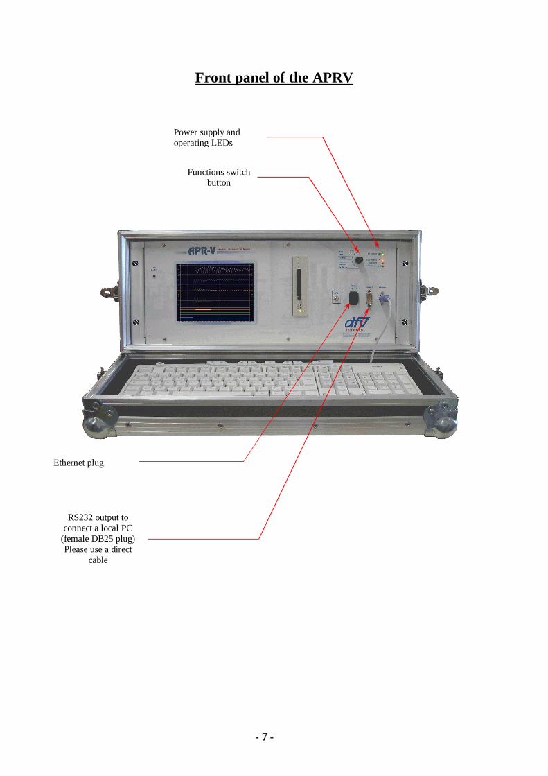
Front panel of the APRV
RS232 output to connect a local PC
(female DB25 plug) Please use a direct
cable
Functions switch button
Power supply and operating LEDs
Ethernet plug
- 8 -
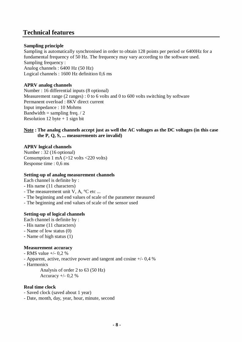
Technical features Sampling principle Sampling is automatically synchronised in order to obtain 128 points per period or 6400Hz for a fundamental frequency of 50 Hz. The frequency may vary according to the software used. Sampling frequency : Analog channels : 6400 Hz (50 Hz) Logical channels : 1600 Hz definition 0,6 ms APRV analog channels Number : 16 differential inputs (8 optional) Measurement range (2 ranges) : 0 to 6 volts and 0 to 600 volts switching by software Permanent overload : 8KV direct current Input impedance : 10 Mohms Bandwidth = sampling freq. / 2 Resolution 12 byte + 1 sign bit Note : The analog channels accept just as well the AC voltages as the DC voltages (in this case
the P, Q, S, ... measurements are invalid) APRV logical channels Number : 32 (16 optional) Consumption 1 mA (>12 volts <220 volts) Response time : 0,6 ms Setting-up of analog measurement channels Each channel is definite by : - His name (11 characters) - The measurement unit V, A, °C etc ... - The beginning and end values of scale of the parameter measured - The beginning and end values of scale of the sensor used Setting-up of logical channels Each channel is definite by : - His name (11 characters) - Name of low status (0) - Name of high status (1) Measurement accuracy - RMS value +/- 0,2 % - Apparent, active, reactive power and tangent and cosine +/- 0,4 % - Harmonics
Analysis of order 2 to 63 (50 Hz) Accuracy +/- 0,2 %
Real time clock - Saved clock (saved about 1 year) - Date, month, day, year, hour, minute, second
- 9 -
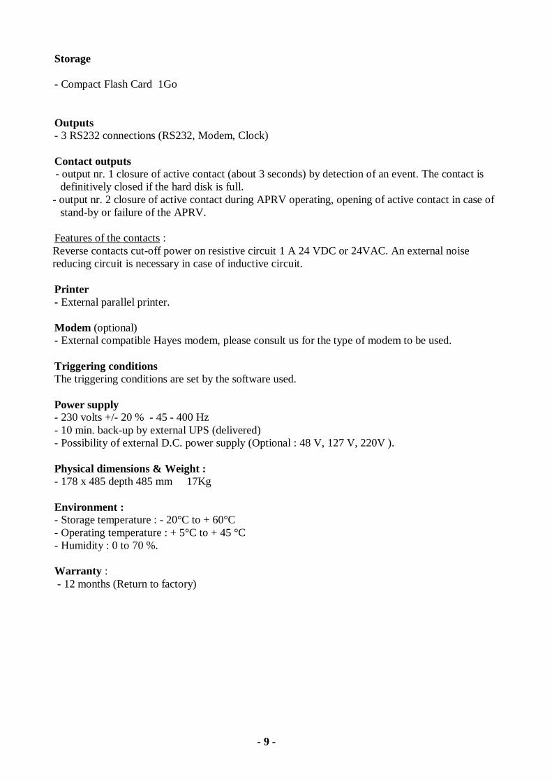
Storage - Compact Flash Card 1Go Outputs - 3 RS232 connections (RS232, Modem, Clock) Contact outputs - output nr. 1 closure of active contact (about 3 seconds) by detection of an event. The contact is
definitively closed if the hard disk is full. - output nr. 2 closure of active contact during APRV operating, opening of active contact in case of
stand-by or failure of the APRV. Features of the contacts : Reverse contacts cut-off power on resistive circuit 1 A 24 VDC or 24VAC. An external noise reducing circuit is necessary in case of inductive circuit. Printer - External parallel printer. Modem (optional) - External compatible Hayes modem, please consult us for the type of modem to be used. Triggering conditions The triggering conditions are set by the software used. Power supply - 230 volts +/- 20 % - 45 - 400 Hz - 10 min. back-up by external UPS (delivered) - Possibility of external D.C. power supply (Optional : 48 V, 127 V, 220V ). Physical dimensions & Weight : - 178 x 485 depth 485 mm 17Kg Environment : - Storage temperature : - 20°C to + 60°C - Operating temperature : + 5°C to + 45 °C - Humidity : 0 to 70 %. Warranty : - 12 months (Return to factory)
- 10 -
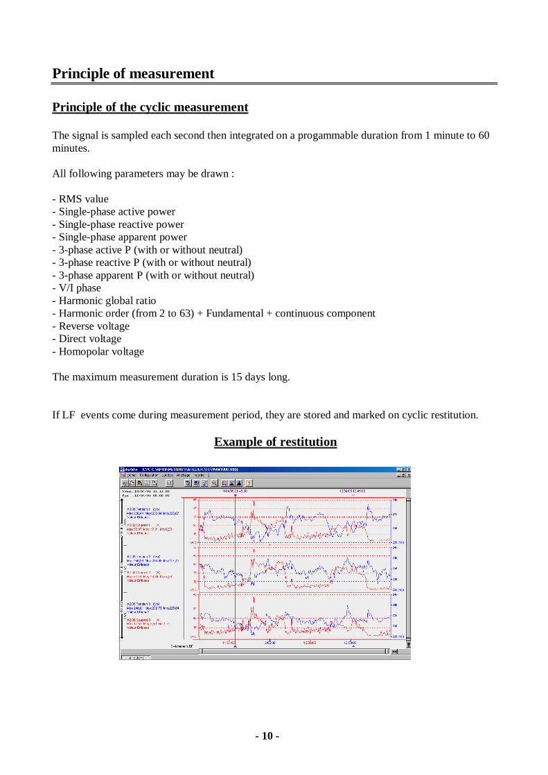
Principle of measurement Principle of the cyclic measurement The signal is sampled each second then integrated on a progammable duration from 1 minute to 60 minutes. All following parameters may be drawn : - RMS value - Single-phase active power - Single-phase reactive power - Single-phase apparent power - 3-phase active P (with or without neutral) - 3-phase reactive P (with or without neutral) - 3-phase apparent P (with or without neutral) - V/I phase - Harmonic global ratio - Harmonic order (from 2 to 63) + Fundamental + continuous component - Reverse voltage - Direct voltage - Homopolar voltage The maximum measurement duration is 15 days long. If LF events come during measurement period, they are stored and marked on cyclic restitution.
Example of restitution
- 11 -
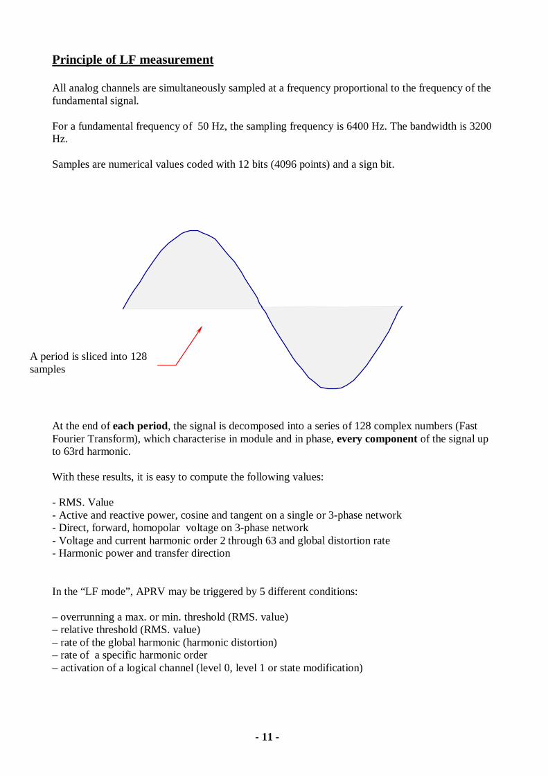
Principle of LF measurement All analog channels are simultaneously sampled at a frequency proportional to the frequency of the fundamental signal. For a fundamental frequency of 50 Hz, the sampling frequency is 6400 Hz. The bandwidth is 3200 Hz. Samples are numerical values coded with 12 bits (4096 points) and a sign bit.
At the end of each period, the signal is decomposed into a series of 128 complex numbers (Fast Fourier Transform), which characterise in module and in phase, every component of the signal up to 63rd harmonic. With these results, it is easy to compute the following values: - RMS. Value - Active and reactive power, cosine and tangent on a single or 3-phase network - Direct, forward, homopolar voltage on 3-phase network - Voltage and current harmonic order 2 through 63 and global distortion rate - Harmonic power and transfer direction In the “LF mode”, APRV may be triggered by 5 different conditions: – overrunning a max. or min. threshold (RMS. value) – relative threshold (RMS. value) – rate of the global harmonic (harmonic distortion) – rate of a specific harmonic order – activation of a logical channel (level 0, level 1 or state modification)
A period is sliced into 128 samples
- 12 -
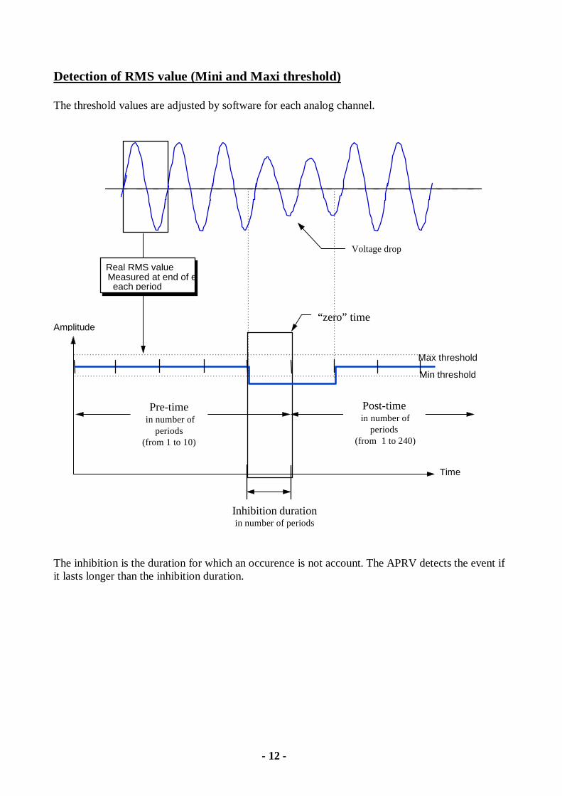
Detection of RMS value (Mini and Maxi threshold) The threshold values are adjusted by software for each analog channel.
Max threshold
Min threshold
Time
Amplitude
Real RMS valueMeasured at end of e
each period
Pre-time in number of
periods(from 1 to 10)
Post-time in number of
periods (from 1 to 240)
“zero” time
Inhibition durationin number of periods
Voltage drop
The inhibition is the duration for which an occurence is not account. The APRV detects the event if it lasts longer than the inhibition duration.

- 13 -
Detection on a relative variation of amplitude (dV/dT or dI/dT)
Max thresholdMin threshold
Time
Amplitude
integer time
in number of periods
Real RMS valuemeasured at end
of each period
Duration in number of periods
Amplitude
Amplitude
The relative threshold is fixed by
- the duration - the amplitude
"Zero" time
Pre-time innumber of
periods(from 1 to 10)
Post-timein number of
periods(from 1 to 240)
the relativethreshold is validin positive andnegative value
- 14 -
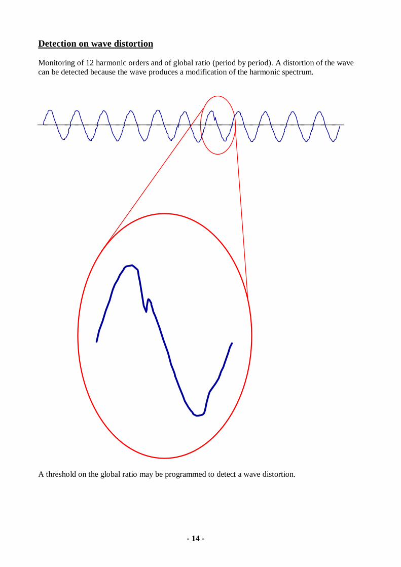
Detection on wave distortion Monitoring of 12 harmonic orders and of global ratio (period by period). A distortion of the wave can be detected because the wave produces a modification of the harmonic spectrum.
A threshold on the global ratio may be programmed to detect a wave distortion.

- 15 -
Example of printing of the cyclic curves:
- 16 -
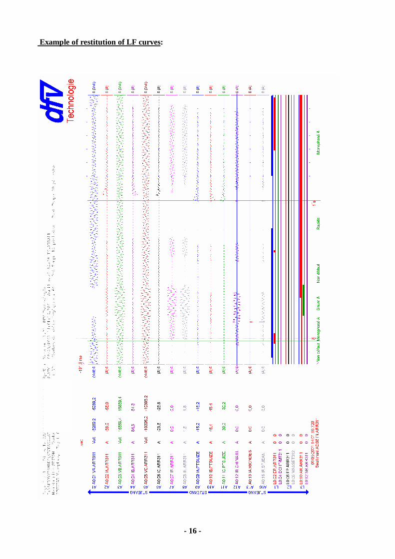
Example of restitution of LF curves: