APPLICATION PROFILE - Fire Protection Technologies · · 2014-01-16APPLICATION PROFILE ......
17
APPLICATION PROFILE Form No. EAP 1016 EXPLOSIONS IN CEMENT PLANTS • Cement manufacturing is one of the largest mineral commodity industries in the United States, with an estimated production capacity of greater than 73 million metric tons annually. • Essentially the heart and soul of the cement manufacturing process, the kiln is a horizontal steel cylinder, lined with firebrick and sloped slightly downward, from the raw material feed to the fuel feed supply and burner pipe. Typically, kilns will rotate at one to three revolutions per minute, heating the raw material mix to a red-hot 2,500-plus degree often form that emerges from the lower end of the kiln in the form of very hot, marble-sized chunks known as “clinker.” Once out of the kiln the clinker goes through a cooling process. When cool, the clinker is ready to pass through a series of grinding and milling processes that result in the gray powder we know as cement. • The cement industry is very capital intensive. Some of the major pieces of equipment include pulverizers, dust collectors, electrostatic precipitators, and rotary kilns. • Energy costs can account for up to 40 percent of the total cost of cement manufacturing. Currently, over 90 percent of the installed capacity uses coal as the primary fuel. Conversion to coal was started in the 1970’s. In 1972, only 39 percent of the industry’s energy was supplied by coal. • Inland Cement, “We are also concerned about the potential fire and explosion hazard of working with coal and are confident that we can use coal safely. Coal has been the fuel of choice for the cement industry around the world for many years and the technology is well developed to prevent fires and explosions. EXPLOSIONS IN CEMENT PLANTS • Coal is fed into a pulverizer where it is crushed and dried using hot air at approximately 300°F. The pulverized coal is then pneumatically transported to the dust collector where the pulverized coal is collected and either fed directly to the burner at the kiln or to a storage bin. • During normal operation the coal stream is inerted with nitrogen or similar gas. The problem typically occurs during startup, shutdown or failure of the inerting system. • It is not uncommon for tramp metal, railroad spikes, or similar metal objects to be fed into the grinder and thus create sparks. These sparks can travel from the pulverizer through the transport pipe and into the dust collector. • Another source of ignition in the dust collector is static electricity. The atmosphere in the dust collector is typically at ~200°F with the dry coal dust suspended. These conditions increase the risk of explosions in the dust collector. • The other common ignition source is pyrites that are collected below the pulverizing bed. If there is a failure of the inert gas source then air is introduced and pyrites can ignite the coal dust. • Coal is milled to a fine powder in a pulverizer - this increases the surface area of the coal and hence the rate of combustion. The powdered coal is blown into the combustion chamber of the burner nozzle where it is burnt at around 1400°C. • The Mine Safety and Health Administration (MSHA) a branch of the U.S. Department of Labor reports that during the past 5 months, eight explosions have occurred, resulting in one fatality and nine nonfatal injuries. Six of these explosions occurred in cement plants. CEMENT PLANT EQUIPMENT WITH HIGHEST EXPLOSION POTENTIAL As reported by Factory Mutual, electric-generating plants experienced losses of greater than $26,000,000 over the last ten yeras due to explosions. Coal dust explosions were the cause of twenty-seven losses. Forty-seven percent of kiln losses occurred in the cement industry. A typical plant layout of a coal burning cement plant is shown in the next diagram. The equipment shown in red are the ones most likely to have explosions and the need for explosion protection. Each of these pieces of equipment is descrbed in greater detail in the remainder of the document: • Kiln • Pulverizer • Dust Collection • Cyclone • Electrostatic Precipitator • Storage bins and silos • Transport pipes and ducts 704 SW 10th Street P.O. Box 610 Blue Springs, Missouri 64013-0610 U.S.A. Phone: 8162293405 www.fike.com
Transcript of APPLICATION PROFILE - Fire Protection Technologies · · 2014-01-16APPLICATION PROFILE ......

APPLICATION PROFILE
Form No. EAP 1016
EXPLOSIONS IN CEMENT PLANTS
• Cement manufacturing is one of the largest mineral commodity industries in the United States, with an estimated production capacity of greater than 73 million metric tons annually.
• Essentially the heart and soul of the cement manufacturing process, the kiln is a horizontal steel cylinder, lined with firebrick and sloped slightly downward, from the raw material feed to the fuel feed supply and burner pipe. Typically, kilns will rotate at one to three revolutions per minute, heating the raw material mix to a red-hot 2,500-plus degree often form that emerges from the lower end of the kiln in the form of very hot, marble-sized chunks known as “clinker.” Once out of the kiln the clinker goes through a cooling process. When cool, the clinker is ready to pass through a series of grinding and milling processes that result in the gray powder we know as cement.
• The cement industry is very capital intensive. Some of the major pieces of equipment include pulverizers, dust collectors, electrostatic precipitators, and rotary kilns.
• Energy costs can account for up to 40 percent of the total cost of cement manufacturing. Currently, over 90 percent of the installed capacity uses coal as the primary fuel. Conversion to coal was started in the 1970’s. In 1972, only 39 percent of the industry’s energy was supplied by coal.
• Inland Cement, “We are also concerned about the potential fire and explosion hazard of working with coal and are confident that we can use coal safely. Coal has been the fuel of choice for the cement industry around the world for many years and the technology is well developed to prevent fires and explosions.
EXPLOSIONS IN CEMENT PLANTS• Coal is fed into a pulverizer where it is crushed and dried using hot air at approximately 300°F. The pulverized coal is then pneumatically
transported to the dust collector where the pulverized coal is collected and either fed directly to the burner at the kiln or to a storage bin.• During normal operation the coal stream is inerted with nitrogen or similar gas. The problem typically occurs during startup, shutdown or
failure of the inerting system.• It is not uncommon for tramp metal, railroad spikes, or similar metal objects to be fed into the grinder and thus create sparks. These sparks
can travel from the pulverizer through the transport pipe and into the dust collector.• Another source of ignition in the dust collector is static electricity. The atmosphere in the dust collector is typically at ~200°F with the dry
coal dust suspended. These conditions increase the risk of explosions in the dust collector.• The other common ignition source is pyrites that are collected below the pulverizing bed. If there is a failure of the inert gas source then air
is introduced and pyrites can ignite the coal dust. • Coal is milled to a fine powder in a pulverizer - this increases the surface area of the coal and hence the rate of combustion. The powdered
coal is blown into the combustion chamber of the burner nozzle where it is burnt at around 1400°C. • The Mine Safety and Health Administration (MSHA) a branch of the U.S. Department of Labor reports that during the past 5 months, eight
explosions have occurred, resulting in one fatality and nine nonfatal injuries. Six of these explosions occurred in cement plants.
CEMENT PLANT EQUIPMENT WITH HIGHEST EXPLOSION POTENTIALAs reported by Factory Mutual, electric-generating plants experienced losses of greater than $26,000,000 over the last ten yeras due to explosions. Coal dust explosions were the cause of twenty-seven losses. Forty-seven percent of kiln losses occurred in the cement industry. A typical plant layout of a coal burning cement plant is shown in the next diagram. The equipment shown in red are the ones most likely to have explosions and the need for explosion protection. Each of these pieces of equipment is descrbed in greater detail in the remainder of the document:• Kiln• Pulverizer• Dust Collection• Cyclone• Electrostatic Precipitator• Storage bins and silos• Transport pipes and ducts
704 SW 10th Street P.O. Box 610 Blue Springs, Missouri 64013-0610 U.S.A. Phone: 8162293405 www.fike.com

2 of 17
FIKE HARDWARE COMPETITIVE ADVANTAGE • Nozzles and Covers for abrasive transport lines that allow for flush mounting so that the hardware does not extend into the process
stream. As a result the Fike Hardware will last longer.• Extended Nozzles for use in the pulverizer allow the agent to be directed to the protected area. This allows the container to be
mounted on top of the pulverizer rather than going through the sidewall where additional obstructions may be encountered.• Lateral ‘Y’ and Tri-Clover Connection allow for easy maintenance to ensure that pressure ports are not plugged. The lateral ‘Y’ also
helps prevent product impingement onto the pressure detector due to turbulence in the process. • 50 Liter High Rate Discharge containers having a long through distance to cover rotary kilns and large volumes.
RawMill
ElectrostaticPrecipitator
BlendingandStorage
Kiln
Cooling
Clinker Store
Cement Mills
Gypsum
CementSilos
Preheat Tower
CoalMill
Packing
Bulk Loading
WasteFuel

3 of 17Copyright © Fike Corporation All Rights Reserved.Form No. EAP 1016, October 2001. Specifications are subject to change without notice.

CEMENT KILN
FUNCTIONALITY A cement kiln is the world’s largest moving manufacturing machine. Cement kilns are cylindrical ovens, some as long as 1000 feet and as much as 24 feet in diameter. They rotate one to three times every minute. The kilns are mounted at a slight incline. The inside is lined with fire resistant brick. Powdered coal, oil, gas, liquid waste-derived fuel, and solid waste fuel are used to fuel the kiln. Raw material enters the kiln and is heated to over 2700°F. The material leaving the kiln is called clinker. EXPLOSION HISTORY• Loss history for the past twelve years in rotary kilns from FM Global Data Sheet 7-76:
• 18.6% if 43 losses were due to explosions• 45% of 43 losses were in a cement industry
CAUSES OF EXPLOSION • Poor combustion - flame temperatures low• Combustion upset caused by product slide• Firing increased too rapidly at startup• Waste fuel gas accumulation• Ignition sources continuously present
Figure 1: Typical Cross-Sectional View of a Cement Kiln
4 of 17

SOLUTION Kilns are best protected by an explosion suppression system. Suppression containers should be used on the inlet and outlet to suppress the deflagration and to prevent flame propagation to other equipment.
Figure 2: Kiln Protected by Explosion Suppression and Chemical Isolation
Copyright © Fike Corporation All Rights Reserved.Form No. EAP 1017, October 2001. Specifications are subject to change without notice.
5 of 17
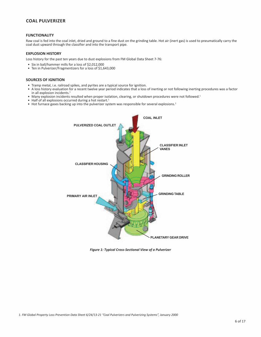
COAL PULVERIZER
FUNCTIONALITY Raw coal is fed into the coal inlet, dried and ground to a fine dust on the grinding table. Hot air (inert gas) is used to pneumatically carry the coal dust upward through the classifier and into the transport pipe.
EXPLOSION HISTORY Loss history for the past ten years due to dust explosions from FM Global Data Sheet 7-76: • Six in ball/hammer mills for a loss of $2,012,000• Ten in Pulverizer/Fragmentizers for a loss of $1,643,000
SOURCES OF IGNITION • Tramp metal, i.e. railroad spikes, and pyrites are a typical source for ignition.• A loss history evaluation for a recent twelve year period indicates that a loss of inerting or not following inerting procedures was a factor
in all explosion incidents.1
• Many explosion incidents resulted when proper isolation, clearing, or shutdown procedures were not followed.1
• Half of all explosions occurred during a hot restart.1
• Hot furnace gases backing up into the pulverizer system was responsible for several explosions.1
COAL INLET
PULVERIZED COAL OUTLET
CLASSIFIER INLETVANES
CLASSIFIER HOUSING
GRINDING ROLLER
GRINDING TABLEPRIMARY AIR INLET
PLANETARY GEAR DRIVE
Figure 1: Typical Cross-Sectional View of a Pulverizer
1. FM Global Property Loss Prevention Data Sheet 6/24/13-21 “Coal Pulverizers and Pulverizing Systems”, January 2000
6 of 17

Copyright © Fike Corporation All Rights Reserved.Form No. EAP 1009, October 2001. Specifications are subject to change without notice.
SOLUTION Explosion Venting of the pulverizer is not allowed per NFPA 8503 of FM 6-24/13-21, so this equipment is best protected by either containment (tested to 200 psig), or an explosion suppression system. Chemical isolation should be used on the inlet and outlet to prevent flame propagation to other equipment.
Figure 2: Pulverizer Protected by Explosion Suppression and Chemical Isolation
7 of 17

DUST COLLECTOR
FUNCTIONALITY A dust collector (bag house) is typically a low strength enclosure that separates dust from a gas stream by passing the gas through a media filter. The dust is collected on either the inside or the outside of the filter. A pulse of air or mechanical vibration removes the layer of dust from the filter. This type of filter is typically efficient when particle sizes are in the 0.01 to 20 micron range. EXPLOSION HISTORY• Loss history shows that dust collectors are by far the leading piece of equipment to experience explosions.1
• Loss history for the past ten years due to dust explosions from FM Global Data Sheet 7-76:• Fifty-eight in dust collectors for a loss off $15,094,000.
SOURCES OF IGNITION• Because dust collectors are designed to handle material produced elsewhere, the ignition source does not have to
come from within the dust collector. It may come from other equipment downstream of the dust collector. • Sparks, flame, or smoldering embers, from dust production areas, are potential ignition sources that can ignite an
explosion in the dust collector.
Figure 1: Sectional View of a Dust Collector
1. FM Global Property Loss Prevention Data Sheet 6/24/13-21 “Coal Pulverizers and Pulverizing Systems”, January 2000
8 of 17

Copyright © Fike Corporation All Rights Reserved.Form No. EAP 1010, October 2001. Specifications are subject to change without notice.
SOLUTION Dust collectors are best protected by either explosion venting and/or explosion suppression systems. In both cases chemical isolation should be used on the inlet to prevent flame propagation to other equipment.
Figure 2: Dust Collector Protected by Explosion Suppression and Chemical Isolation
Figure 3: Dust Collector Protected by Explosion Venting and Chemical Isolation
9 of 17

CYCLONE
FUNCTIONALITY Dust laden gas enters the chamber from a tangential direction at the outer wall of the device, forming a vortex as it swirls within the chamber. The larger particulates, because of their greater inertial, move outward and are forced against the chamber wall. Slowed by friction with the wall surface, they then slide down the wall into a conical dust hopper at the bottom of the cyclone. The cleaned air swirls upward in a narrower spiral through an inner cylinder and emerges from an outlet at the top. Accumulated particulate dust is deposited into a hopper, dust bin or screw conveyor at the base of the collector. Cyclones are best at removing relatively coarse particulates. They can routinely achieve efficiencies of 90% for particles larger than about 20 µm (0.008 inch). By themselves, however, cyclones are not sufficient to meet stringent air quality standards. They are typically used as pre-cleaners and are followed by more efficient air cleaning equipment such as electrostatic precipitators and bag houses. EXPLOSION HISTORY• Loss history for the past ten years due to dust explosions from FM Global Data Sheet 7-76:
• Twenty-seven losses involved coal dust for a loss of $12,056,000
Figure 1: Cyclone Operation
10 of 17

Copyright © Fike Corporation All Rights Reserved.Form No. EAP 1011, October 2001. Specifications are subject to change without notice.
SOURCES OF IGNITION Because cyclone collectors are designed to handle material produced elsewhere, the ignition source does not have to come from within the cyclone collector. It may come from other equipment upstream or downstream of the cyclone. Sparks, flame, or smoldering embers, from dust production areas, are potential ignition sources that can ignite an explosion in the cyclone collector.
SOLUTION Cyclone collectors are best protected by explosion suppression systems. Chemical isolation should be used on the inlet and outlet to prevent flame propagation to other equipment.
Figure 2: Cyclone Protected by Explosion Suppression and Chemical Isolation
11 of 17

ELECTROSTATIC PRECIPITATOR
FUNCTIONALITY In an electrostatic precipitator, particles suspended in the air stream are given an electric charge as they enter the unit and are then removed by the influence of an electric field. A high DC voltage (as much as 100,000 volts) is applied to the discharge electrodes to charge the particles, which then are attracted to oppositely charged collection electrodes, on which they become trapped.
Particles that stick to the collection plates are removed periodically when the plates are shaken or “rapped.” Rapping is a mechanical technique for separating the trapped particles from the plates, which typically become covered with a 6-mm (0.2 inch) layer of dust. An electrostatic precipitator can remove particulates as small as 1 µm (0.00004 inch) with an efficiency exceeding 99%. The effectiveness of electrostatic precipitators in removing fly ash from the combustion gases of fossil-fuel furnaces accounts for their high frequency of use at power stations. EXPLOSION HISTORY• Loss history for the past ten years due to dust explosions from FM Global Data Sheet 7-76:
• Four in electrostatic precipitators for a loss of $2,988,000 SOURCES OF IGNITION Due to continuous spark generation and mechanical rapping, ignition sources are readily present in the electrostatic precipitator. Because electrostatic precipitators are designed to handle material produced elsewhere, the ignition source does not have to come from within the electrostatic precipitator.
Figure 1: Sectional View of an Electrostatic Precipitator
12 of 17

Copyright © Fike Corporation All Rights Reserved.Form No. EAP 1012, October 2001. Specifications are subject to change without notice.
SOLUTION One way of protecting electrostatic precipitators is through the use of explosion venting. Chemical isolation should be used on the inlet to prevent flame propagation to other equipment.
Figure 2: Electrostatic Precipitator Protected by Explosion Venting and Chemical Isolation
13 of 17

STORAGE BIN
FUNCTIONALITYA storage bin can contain either raw coal for feeding into the pulverizer, or pulverized coal for feeding into the burner. Typically coal is fed into the top of the storage bin. The heavy particles of coal settle in the hopper, while dust becomes suspended in the upper section. The dust can be the fines created during pulverizing, or the fines that are a by-product of abrasion as the coal being moved from one piece of equipment to another. EXPLOSION HISTORY • Loss history for the past ten years due to dust explosions from FM Global Data Sheet 7-76:
• Seven in storage silos/bins for a loss of $4,002,000 SOURCES OF IGNITION Due to continuous spark generation and mechanical rapping, ignition sources are readily present in the electrostatic precipitator. Because electrostatic precipitators are designed to handle material produced elsewhere, the ignition source does not have to come from within the electrostatic precipitator.
Figure 1: Sectional View of a Storage Bin
14 of 17

Copyright © Fike Corporation All Rights Reserved.Form No. EAP 1013, October 2001. Specifications are subject to change without notice.
SOLUTION One way of protecting electrostatic precipitators is through the use of explosion venting. Chemical isolation should be used on the inlet to prevent flame propagation to other equipment.
Figure 2: Storage Bin Protected by Explosion Suppression and Chemical Isolation
15 of 17

DUCTS AND PIPES
FUNCTIONALITY Transport pipes and ducts are enclosures that move coal dust from one piece of equipment to another, or that brings heated gases into the equipment for process operation. These enclosures can range from lightweight sheet metal to heavy wall pipe. They can be round with diameters up to approximately 5 feet, or rectangular with cross sections up to approximately 2’x3’ EXPLOSION HISTORY• Damage to transport pipes and ducts are usually the result of an explosion in a connected piece of equipment. For example,
an explosion that occurred in the pulverizer usually damages the pulverizer heated gas inlet, because the inlet is of lightweight construction.
• Loss history for the past ten years due to dust explosions from FM Global Data Sheet 7-76:• Eight in coal processing for a loss of $4,654,000
SOURCES OF IGNITION Sparks, flame, or smoldering embers are potential ignition sources that can ignite an explosion in transport pipes and ducts.
Figure 1: Ducts and Pipes
16 of 17
Copyright © Fike Corporation All Rights Reserved.Form No. EAP 1014, October 2001. Specifications are subject to change without notice.
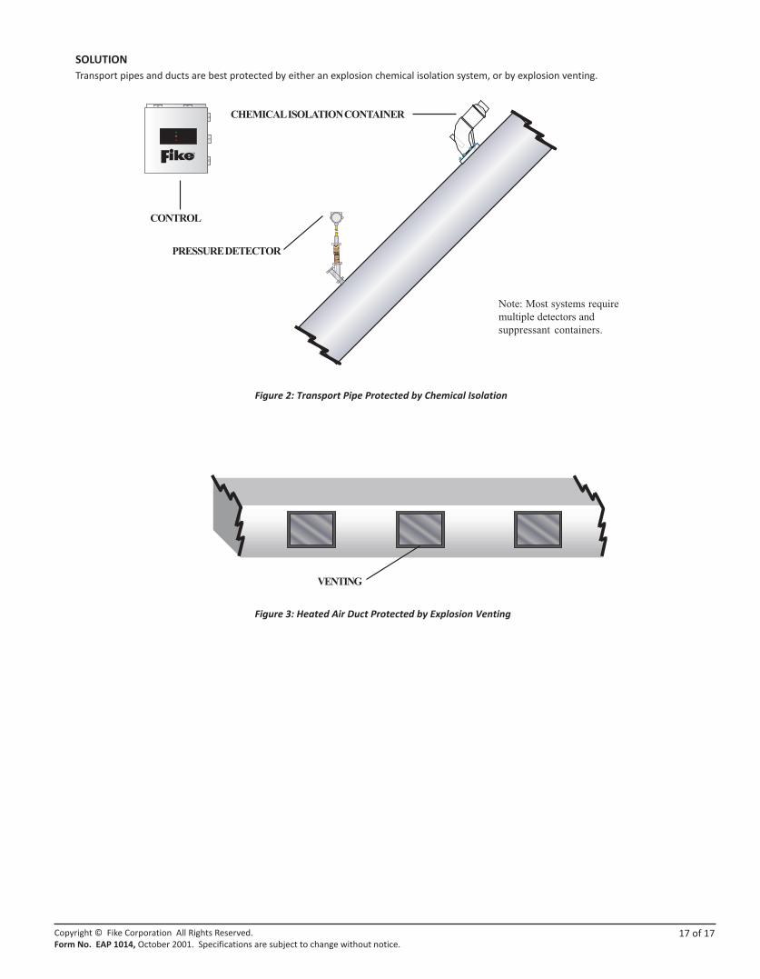
SOLUTION Transport pipes and ducts are best protected by either an explosion chemical isolation system, or by explosion venting.
Figure 2: Transport Pipe Protected by Chemical Isolation
Figure 3: Heated Air Duct Protected by Explosion Venting
17 of 17