Application for an IPPC Licence Proposed Biodiesel Plant … · 2013-07-25 · Application for an...
25
Proposed Biodiesel Plant Proposed Biodiesel Plant Marshmeadows Marshmeadows , , New Ross, New Ross, Co. Wexford. Co. Wexford. MALONE O’REGAN ENVIRONMENTAL SERVICES LTD 2B Richview Office Park Clonskeagh Dublin 14 Application for an IPPC Licence Application for an IPPC Licence July 2007 July 2007 Green Biofuels Ireland Limited IPPCL Form Attachments For inspection purposes only. Consent of copyright owner required for any other use. EPA Export 25-07-2013:21:59:26
Transcript of Application for an IPPC Licence Proposed Biodiesel Plant … · 2013-07-25 · Application for an...

Proposed Biodiesel PlantProposed Biodiesel Plant
MarshmeadowsMarshmeadows, ,
New Ross,New Ross,
Co. Wexford.Co. Wexford.
MALONE O’REGANENVIRONMENTAL SERVICES LTD
2B Richview Office Park
ClonskeaghDublin 14
Application for an IPPC LicenceApplication for an IPPC Licence
July 2007July 2007
Green Biofuels Ireland Limited
IPPCL Form Attachments
For
insp
ectio
n pur
pose
s only
.
Conse
nt of
copy
right
owne
r req
uired
for a
ny ot
her u
se.
EPA Export 25-07-2013:21:59:26

Green Biofuels Ireland Ltd. July 2007 Application for an IPPC Licence Attachment A.1– Non Technical Summary
__________________________________________________________________________ Malone O’Regan
Green Biofuels Ireland Ltd. Application for an
IPPC Licence
Attachment A.1
Non Technical Summary
For
insp
ectio
n pur
pose
s only
.
Conse
nt of
copy
right
owne
r req
uired
for a
ny ot
her u
se.
EPA Export 25-07-2013:21:59:26

Green Biofuels Ireland Ltd. July 2007 Application for an IPPC Licence Attachment A.1 – Non Technical Summary
Malone O’Regan 1
Table of Contents Section Page No 1.0 Introduction ……………………………………………….... 2 2.0 Existing Site Conditions …………………………………. 2 3.0 Description of Activity ……………………………………. 3 4.0 Installation and Infrastructure …………………………… 4 5.0 Plant Operating Capacity …………………………………. 4 6.0 Process Raw Materials and Auxiliary Materials ……… 5 7.0 Energy Used / Generated ………………………………… 5 8.0 Source of Emissions ……………………………………… 5 9.0 Nature and Quantities of Emissions, Considerati on
of BAT and Impact on the Environment ………………. 7
10.0 Avoidance, Prevention and Recovery of Waste ……… 10 11.0 Energy Efficiency ………………………………………….. 11 12.0 Accidents and their Consequences ……………………. 12 13.0 Monitoring …………………………………………………… 13 14.0 Decommissioning Plans ………………………………..... 13 Figures Figure 1 Site Location Map Figure 2 Site Layout Map Figure 3 Ground Floor and Tank Farm Layout Appendices A.1.1 Conceptual Plan and Photo of Scottish Plant A.1.2 Block Diagram of Inputs, Outputs and Emissions
For
insp
ectio
n pur
pose
s only
.
Conse
nt of
copy
right
owne
r req
uired
for a
ny ot
her u
se.
EPA Export 25-07-2013:21:59:26
Green Biofuels Ireland Ltd. July 2007 Application for an IPPC Licence Attachment A.1 – Non Technical Summary
Malone O’Regan 2
1.0 Introduction Green Biofuels Ireland Ltd. (GBI) wishes to apply for an IPPCL from the EPA and commence the manufacture of BioDiesel at a purpose built BioDiesel production facility at New Ross Port, Marshmeadows, Co. Wexford. The location of the proposed development is shown on Figure 1. The plant is currently under construction and is expected to be complete early 2008.
The proposed plant will convert, via a process known as trans-esterification, renewable, indigenous resources such as rapeseed oil, tallow and used vegetable cooking oils to a high quality, biodegradable fuel (BioDiesel) meeting the EU quality standard EN14214 for use as a safe, sustainable, cleaner alternative to petroleum diesel. BioDiesel can be used in conventional combustion ignition engines as part of a blend or neat; thereby reducing emissions to air of hydrocarbons, carbon monoxides and particulates. It is considered to be a carbon neutral and energy positive fuel. BioDiesel production is listed under the IPPCL Directive (96/61/EC) under the following activity:
4. Chemical Industry Production within the meaning of the categories of activities contained in this section means the production on an industrial scale by chemical processing of substances or groups of substances listed in Sections 4.1 to 4.6. 4.1. Chemical installations for the production of basic organic chemicals, such as:
(b) oxygen-containing hydrocarbons such as alcohols, aldehydes, ketones, carboxylic acids, esters, acetates, ethers, peroxides, epoxy resins.
The above is transposed into Irish law within the Protection of the Environment Act, 2003, within Class 5 listed in the Schedule of Activities. All of the documents contained within this folder represent an application to the EPA for an IPPCL under the Environmental Protection Agency Act, 1992 as amended by the Protection of the Environment Act, 2003.This application has been prepared for GBI by Malone O Regan Environmental Services Ltd. This section of the application package constitutes a Non Technical Summary required under Part A of the IPPCL application form. 2.0 Existing Site Conditions The site comprises 0.87 ha and is located approximately 1.75km south of O’Hanrahan’s bridge (the main bridge on the N25) at New Ross, on the eastern bank of the River Barrow, in County Wexford as illustrated on Figure 1. The site lies within the Barrow River Valley with the ground sloping up and away from the site to the east. The town of New Ross lies just north of the site and rises up above the river. The BioDiesel plant is presently being constructed and to date the site has been cleared of vegetation and clean fill has been imported to provide a uniform level throughout the site. Piling has been carried out for the proposed tank farm and process buildings. A site office and compound has been set up in the north eastern corner of the site.
For
insp
ectio
n pur
pose
s only
.
Conse
nt of
copy
right
owne
r req
uired
for a
ny ot
her u
se.
EPA Export 25-07-2013:21:59:26

Green Biofuels Ireland Ltd. July 2007 Application for an IPPC Licence Attachment A.1 – Non Technical Summary
Malone O’Regan 3
Prior to the recent construction phase for the BioDiesel plant, the site had been filled up to 1m in the recent past with modern clean fill material and was disused and covered in scrub vegetation. There is no record of any industrial or commercial activity on the site. Prior to this the site along with the overall Marshmeadows area would have been reclaimed from the river in the 1800’s for agricultural use. 3.0 Description of Activity Vegetable oils, used cooking oil and animal fat represent a very high-grade source of fuel when they are chemically changed (transesterificated). From a chemistry perspective these feedstock materials consist of free fatty acids and triglycerides - three long-chain fatty acids attached to a trivalent alcohol, the glycerine. In the proposed development Green Biofuels will carry out the transesterification process to convert indigenous raw materials into BioDiesel by removing the glycerine (trivalent alcohol) component and substituting it with a monohydric alcohol. Traditionally, the transesterification reaction normally took place at raised temperatures and pressures. However the state of the art BDI process, through the use of a suitable catalyst, allows the transesterification process to take place at lower temperatures and pressures. The BioDiesel obtained is a 100% substitute for ordinary fossil fuel derived diesel. It is also possible to blend BioDiesel with fossil diesel in any ratio. The following core activities will be carried out:
1. Materials receipt and storage. 2. Fatty acid esterification: raw materials with high FFAs (free fatty acids) and
methanol are combined in the presence of a sulphuric acid and phosphoric acid catalyst.
3. Potassium methanolate (catalyst) production: the mixing of potassium hydroxide and methanol to form potassium methanolate.
4. Transesterification: mixing the oils and esterified fatty acids and potassium methanolate.
5. Washing: removal of impurities (potassium salts etc) from the BioDiesel. 6. Distillation of product: removal of water, salts and organic impurities via a
distillation process. 7. By-product acidification: Addition of sulphuric acid to produce liquid free fatty
acids, glycerine and potassium sulphate. 8. Potassium sulphate purification: Washing with methanol then drying. 9. Methanol distillation: separation of methanol and water for re-use. 10. Storage of product and by-products: collection, quality testing and storage in
large external storage vessels. Auxiliary activities will include:
1. Laboratory testing. 2. Steam, heat and hot water generation (gas oil/bio-heating fuel oil (BioDiesel)
fired boiler). 3. Deionisation of water supply. 4. Air compression (for process instruments and pneumatic movement of
potassium sulphate powder). 5. Cooling air (for cooling some parts of the process). 6. Chilling air (for chilling some parts of process and cooling water).
For
insp
ectio
n pur
pose
s only
.
Conse
nt of
copy
right
owne
r req
uired
for a
ny ot
her u
se.
EPA Export 25-07-2013:21:59:26
Green Biofuels Ireland Ltd. July 2007 Application for an IPPC Licence Attachment A.1 – Non Technical Summary
Malone O’Regan 4
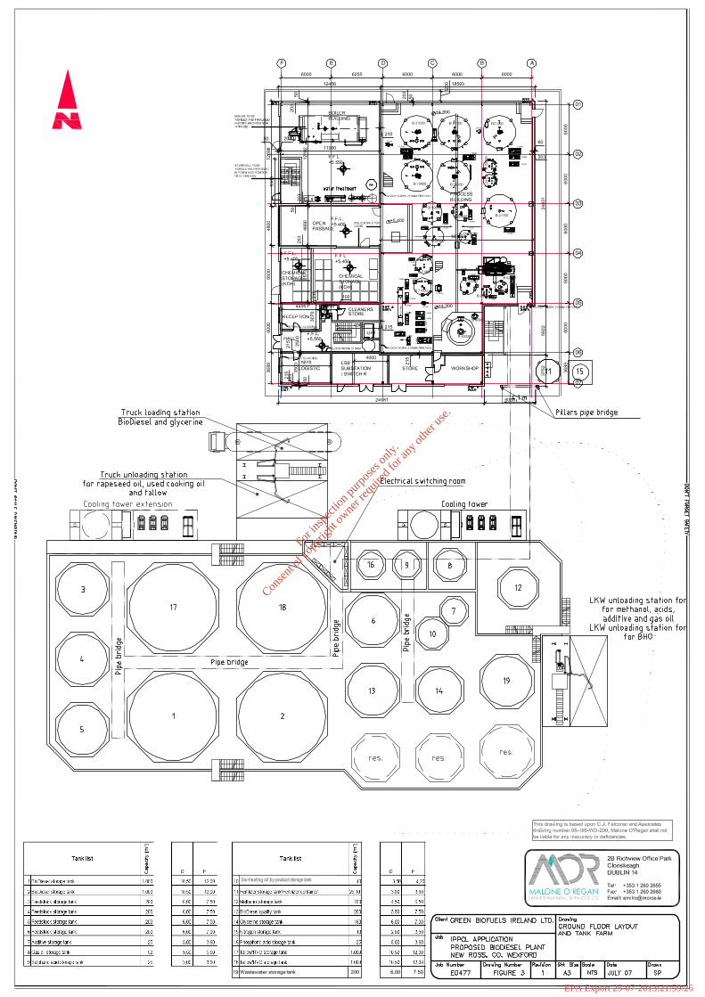
7. Nitrogen generation (inert blanket). 4.0 Installation and Infrastructure The site layout is shown on Figure 2 and will comprise of two main structures; -the main building incorporating the process area, distillation column and utilities area and the tank farm. The remainder of the site is made up of hardstand, parking and landscaping as shown on Figure 2. The ground floor of the process building and a detailed description of the tank farm (incorporating 17 tanks) are given on Figure 3. The main building is split between the process and utility areas and will contain the following: Ground Floor:
- Reception; - Steam Boiler room; - Process area with process vessels; - Workshop and spare parts; - Water deionisation unit; - Logistics room; - Stores; - ESB Substation/Switch room, and - Chemical (potassium hydroxide (KOH)) storage.
Upper Floor (part of utility section only):
- Offices, toilets, changing rooms, electrical room, control room, board room and laboratories.
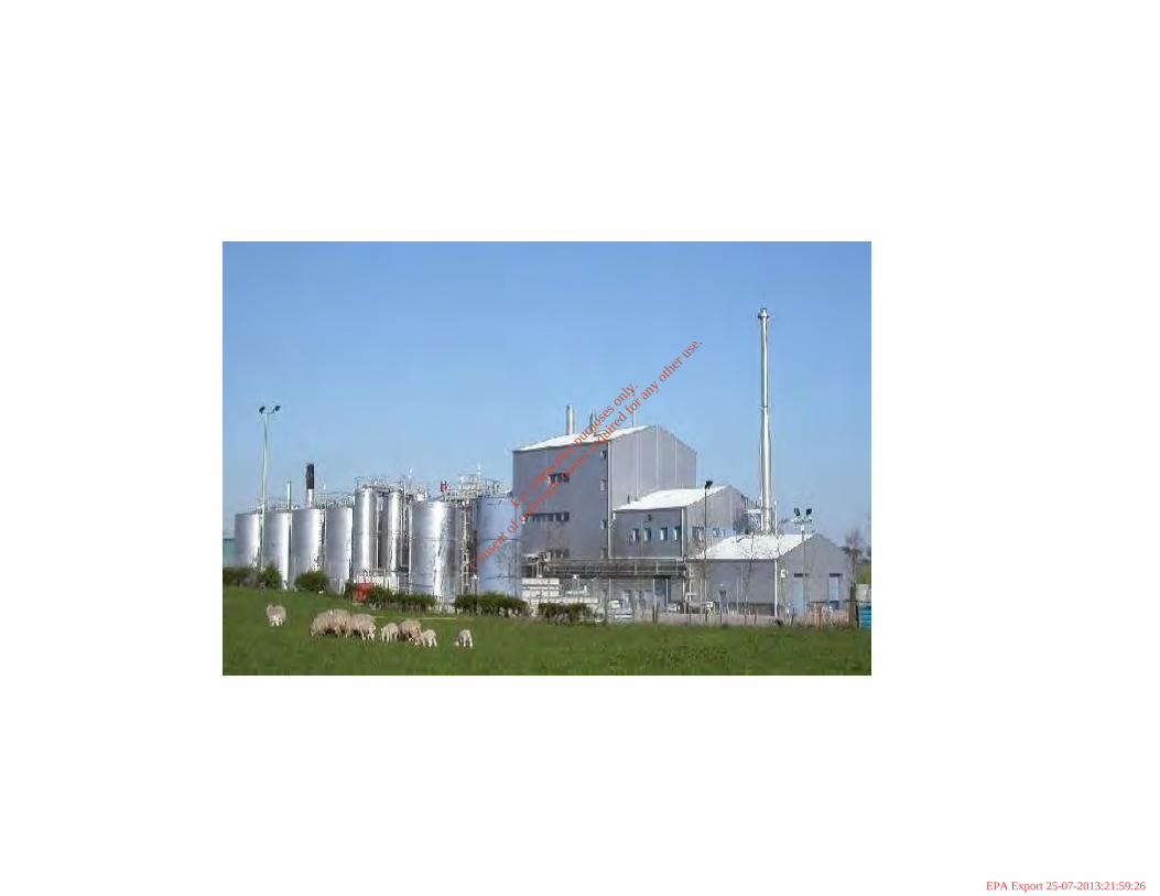
The main process building will be approx. 13.5m high with a column/distillation tower measuring approx. 19.5m in height from ground level. Tanks will range in height from 3.5 to 12m above ground level. Appendix A.1.1 contains an illustration of the BioDiesel plant and a photo of a similar licensed plant run by Argent Energy in Scotland. The site will have separate foul and surface water drainage systems. Process and domestic effluent (8 m3 per day) will drain to the New Ross WWTP due to be built by end of 2008. The BioDiesel plant is likely to be operating before the new WWTP is commissioned, therefore a tank has been provided on site for the storage of wastewater for weekly collection and disposal at Wexford County Council’s WWTP for Wexford town. The site is designed with attenuation systems and shut-off valves with monitoring systems to accommodate firewater retention and/or spills/contaminated water. Water supply (11 m3 per day) will be drawn from the public main on the adjoining R0733. A 7.1MW boiler run on gas oil and/or gas oil / bio-heating oil mix will be used to heat the process. The site will also be served by electricity and telecommunications. 5.0 Plant Operating Capacity The BioDiesel plant is designed as follows: Operating mode: semi-continuous
For
insp
ectio
n pur
pose
s only
.
Conse
nt of
copy
right
owne
r req
uired
for a
ny ot
her u
se.
EPA Export 25-07-2013:21:59:26

Green Biofuels Ireland Ltd. July 2007 Application for an IPPC Licence Attachment A.1 – Non Technical Summary
Malone O’Regan 5
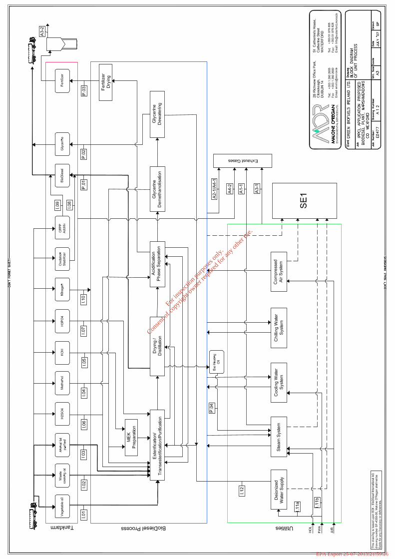
Operating days per year: 330 Operating hours per day: 24 Capacity per hour: 3.79 t Capacity per day: 90.91 t Capacity per year: 30,000 t Annual operating hours: approx. 7,920 hrs 6.0 Process Raw Materials and Auxiliary Materials Relatively few raw and auxiliary materials will be used in the process. The input raw materials comprise tallow, rapeseed oil and recycled vegetable oil. The auxiliary chemicals used comprise methanol, sulphuric acid, potassium hydroxide and phosphoric acid. These raw materials are fundamental to the ‘recipe’ for creation of BioDiesel (fatty acid methyl ester) with the properties required by the European BioDiesel quality standards. The process is extremely efficient in terms of transformation of raw materials into the end product, and is specifically designed as such for economic and environmental reasons. The raw materials used in the process yield three additional saleable by-products – potassium sulphate, glycerine and BioDiesel bio-heating oil – a lower grade BioDiesel suitable for boilers. This minimises production waste generation. The BDI process takes approximately 1000kgs of feedstock, 107kg of methanol and small quantities of potassium hydroxide and sulphuric acid to produce approximately 975kgs of BioDiesel, 99 kgs of crude glycerine and a small quantity of fertiliser and bio-heating oil (biofuel) by-product. 7.0 Energy Used / Generated The plant will be entirely electricity powered, from the National Grid, with the exception of steam generation which will be by a gas oil fired boiler. The Marshmeadows site is currently supplied by an ESB substation with 100mm diameter ESB ducting, which will be extended to serve the proposed BioDiesel plant. The electrical demand is approximately a maximum of 54 kWh/t of feedstock. Feedstock quantity in one year is estimated to be 30,769 t. A total of 54 kWh/t x 30,769 t equates to 1,661,526 kWh, thus approximately 1,661 MWh is estimated as the annual electricity demand. This includes for process, cooling tower, chilling and air compressor, tank farm and excludes steam boiler, lighting and administration electricity requirements. The facility will also have its own ESB substation (with switch-room) located within the curtilage of the plant. The boiler could use a maximum of 2,333 tonnes of gas oil, at a rate of 0.29 tonnes per hour based on 100% gas oil usage. However, it is likely to operate at a much lower fuel use for the majority of the time (60-70% capacity). Also, it is proposed to use bio-heating oil (a lower grade biofuel generated within the process) in a 70:30 mix (i.e. 70% gas oil). This would represent a saving of up to 700 tonnes per annum in fossil fuel usage. 8.0 Sources of Emissions A block diagram showing the inputs and outputs as emissions is contained within Appendix A.1.2.
For
insp
ectio
n pur
pose
s only
.
Conse
nt of
copy
right
owne
r req
uired
for a
ny ot
her u
se.
EPA Export 25-07-2013:21:59:26
Green Biofuels Ireland Ltd. July 2007 Application for an IPPC Licence Attachment A.1 – Non Technical Summary
Malone O’Regan 6
8.1 Emissions to Air The main sources of emissions to air are as follows: Normal Operations:
• Biodiesel manufacturing process ventilation system – point source emission to air of VOCs mainly methanol.
• Boiler Operation – point source emission to air of particulates, CO2, CO, NOx and SOx.
• Laboratory – minor point source emission to air. • Fertiliser Silo – minor point source emission of particulates to air. • Tank Farm Breathing and Working Losses – potential fugitive emissions of
VOCs to air. Abnormal Scenario:
• General building ventilation system – in the unlikely event that methanol concentrations in the process building air were to reach explosive concentrations then the process building is completely vented to atmosphere.
8.2 Emissions to Surface Water The main sources of emissions to surface water are: Normal Operations:
• Surface water run-off from roofs, hardstand and bunded areas. Abnormal Operations:
• None – all surface water will be retained on site in an emergency scenario such as a spill or fire.
8.3 Emissions to Foul Drainage System The main sources of emissions to the public foul drainage system are:
• Process effluent (3-5 m3 per day) from the BioDiesel manufacturing process. • Drying of compressed air. • Process water preparation. • Sanitary wastewater from toilets and canteen. • Weekly cleaning activities. • Wastewater from boiler operations.
A total of 8m3 per day is envisaged. 8.4 Noise Emissions The main internal noise sources are pumps, decanters, boiler, compressed air station. All are enclosed within the process building. The main external noise sources are:
For
insp
ectio
n pur
pose
s only
.
Conse
nt of
copy
right
owne
r req
uired
for a
ny ot
her u
se.
EPA Export 25-07-2013:21:59:26
Green Biofuels Ireland Ltd. July 2007 Application for an IPPC Licence Attachment A.1 – Non Technical Summary
Malone O’Regan 7
• Air fan on cooling tower. • Pressure relief valves on boiler. • Electric motor of tank farm pumps (17 no.). • Pneumatic conveyor on potassium sulphate silo loading. • Liquid nitrogen generator. • Generator hum, electricity substation. • Process building extractor fan.
9.0 Nature and Quantities of Emissions, Considerati on of BAT and Impact
on the Environment 9.1 Emissions to Air Point Source Point source air emissions from the production process will primarily comprise methanol and water vapour. The maximum expected methanol mass flow is in the region of 0.1kg/hr after abatement via a condenser and scrubber. The vapour pressures of the other additives/components to the process are too small to form relevant concentrations. The gas velocities (due to no fans or drawing mechanisms) in the internal pipelines are low and result in the majority of particulates and liquid droplets (water and sulphuric acid) not being carried far along the pipes or will be condensed out within the process. Other components are likely to be less than 20 mg/Nm3. The HMIP publication “Technical Guidance Note (DISPERSION) [D1]” has been employed to determine the worst case stack heights for the process discharge to atmosphere. The maximum expected mass flow was used to determine stack height. Detailed modelling and assessment using real emission levels and local MET. data has not been conducted because the stack height has been set as per the HMIP publication which is calculated as 22.5m above ground level. The emissions comply with the BAT associated emission levels for emissions to air as set out for Organic Substances Class I in the Draft BAT Guidance Note on Best Available Techniques for the Manufacture of Organic Chemicals. Accordingly, the process is not anticipated to adversely impact on ambient air quality. Boiler Emissions The boiler to be used on site for process steam generation will be a 7.1 MW boiler. The boiler will be a low NOx boiler and will incorporate low furnace heat release rates and will incorporate a 19% flue gas recirculation rate. A Saacke forced draught rotary cup burner with dual atomisers and ultra low NOx combustion will be used with the boiler. The technology proposed is considered BAT. Based on a 70:30 mix of gas oil to bioheating oil, and assuming an overall sulphur content of 0.1% mass, boiler emissions are generally expected to be within the emission limit values (ELVs) for NOx and SOx. The HMIP publication “Technical Guidance Note (DISPERSION) [D1]” has been employed to determine the requisite stack height for the boiler discharge to atmosphere.
For
insp
ectio
n pur
pose
s only
.
Conse
nt of
copy
right
owne
r req
uired
for a
ny ot
her u
se.
EPA Export 25-07-2013:21:59:26

Green Biofuels Ireland Ltd. July 2007 Application for an IPPC Licence Attachment A.1 – Non Technical Summary
Malone O’Regan 8
The maximum expected mass flows for particulates, NOx and SOx was used to determine stack height. The stack height had already been set at 24m in the planning permission. Recent data inputted into the D1 calculation indicates that 25m may be required. However this will be further reviewed by the boiler/burner manufacturer and detailed modelling and assessment using real emission levels and local MET. data may also be carried out if required. The D1 calculation is a screening model and therefore tends to overestimate the stack height required. The boiler emissions are therefore not anticipated to adversely impact on ambient air quality and/or Air Quality Standards (AQSs). Fugitive Emissions/Odours No fugitive emissions or odours will be generated during normal operation of the process, as all vessels are closed or vent to the process exhaust system (point source emission). Storage tank vents will have charcoal filters to prevent fugitive odours from the storage facilities. 9.2 Emissions to Surface Water Surface water runoff from roofs, hardstand and roads will discharge to the river via an attenuation tank and petrol interceptor. The final discharge point will be fitted with TOC and pH meters which will be linked to the process control system (PCS) and an automatic shut-off valve should any abnormal changes be detected. The type of interceptor used will be a Klargester NS125 Class 1 Full Retention Oil Interceptor which will be oversized to retain a large volume of material. This will be regularly inspected and emptied as part of the EMS for the plant. The interceptor will be fitted with a high level liquid alarm also linked to the PCS. The surface water discharged post interceptor is expected to be in the range of pH suitable for the protection of freshwater fish, (pH 6 – 9), of ambient temperature and with total hydrocarbons at no more than 0.5 mg/l post interceptor. The post interceptor BOD is expected to be less than 5 mg/l in order for it to retain its surface water classification. Post interceptor suspended sediments are expected to fall below the EQS of ≤ 50 mg/l. Surface water which collects in bunded areas will be visually inspected prior to discharge to the surface water drainage system. The EQSs presented in Table 1 will be complied with. Table 1 Applicable Surface Water EQSs Parameter
Units EQS 1
BOD5 mg/l O2 ≤ 5.0 Oil and Grease (petroleum hydrocarbons)
mg/l No visible film 0.32
Suspended Solids mg/l 50 Temperature - Ambient pH pH units ≥6.0 & ≤ 9.0
- No limit/value - 1 Environmental Quality Standards (EPA, 1997) - 2 for mineral oils
The above is considered BAT for surface water discharges. The surface water run-off from the plant will discharge to the River Barrow candidate Special Area of
For
insp
ectio
n pur
pose
s only
.
Conse
nt of
copy
right
owne
r req
uired
for a
ny ot
her u
se.
EPA Export 25-07-2013:21:59:26

Green Biofuels Ireland Ltd. July 2007 Application for an IPPC Licence Attachment A.1 – Non Technical Summary
Malone O’Regan 9
Conservation. Compliance with the EQSs will ensure that the runoff will not negatively impact on the existing water quality and thus will not impact on listed species. 9.3 Emissions to Foul Drainage The maximum flow of process wastewater is 3-5m3 per day. BioDiesel International has provided the following average figures presented in Table 2 below: Table 2 Wastewater Quality Characteristics Water Quality Parameter
Anticipated Effluent Quality
COD 22,500 mg O2l-1
BOD5 6,000 mg O2l-1
Fats/oils/grease <0.2% Methanol <0.045 – 0.1% pH 5 - 8
Process wastewater will be collected from vessels and piped via the overhead pipebridge across to the tank farm where a sampling manhole on the foul line will be provided for sampling prior to combining it in the main foul sewer with the domestic effluent. In addition to the process wastewater a further 3m3 per day will be generated from the following:
• The boiler will be used to generate steam and hot water. Both the steam and hot water are circulated in closed systems, however a small percentage is blown down regularly and re-supplied from the deionisation plant.
• Minimal quantities of water will condense from the air compressor
(approx.16.8 lt/day). This water will contain some hydrocarbons from the hydraulic oil used in the compressor.
• The demineralisation plant will generate process water for the BioDiesel
process. The estimated amount of wastewater from this process is 100 lt/hr. Plant cleaning will occur weekly. All internal plant areas will have catchpits/sumps for collection of maintenance/washdown. Minimal concentrations of contaminants are expected. Approximately 10 m3 per week of washdown will be generated. The anticipated wastewater quality from the cleaning water mixed with the process wastewater is set out in Table 3:
For
insp
ectio
n pur
pose
s only
.
Conse
nt of
copy
right
owne
r req
uired
for a
ny ot
her u
se.
EPA Export 25-07-2013:21:59:26
Green Biofuels Ireland Ltd. July 2007 Application for an IPPC Licence Attachment A.1 – Non Technical Summary
Malone O’Regan 10
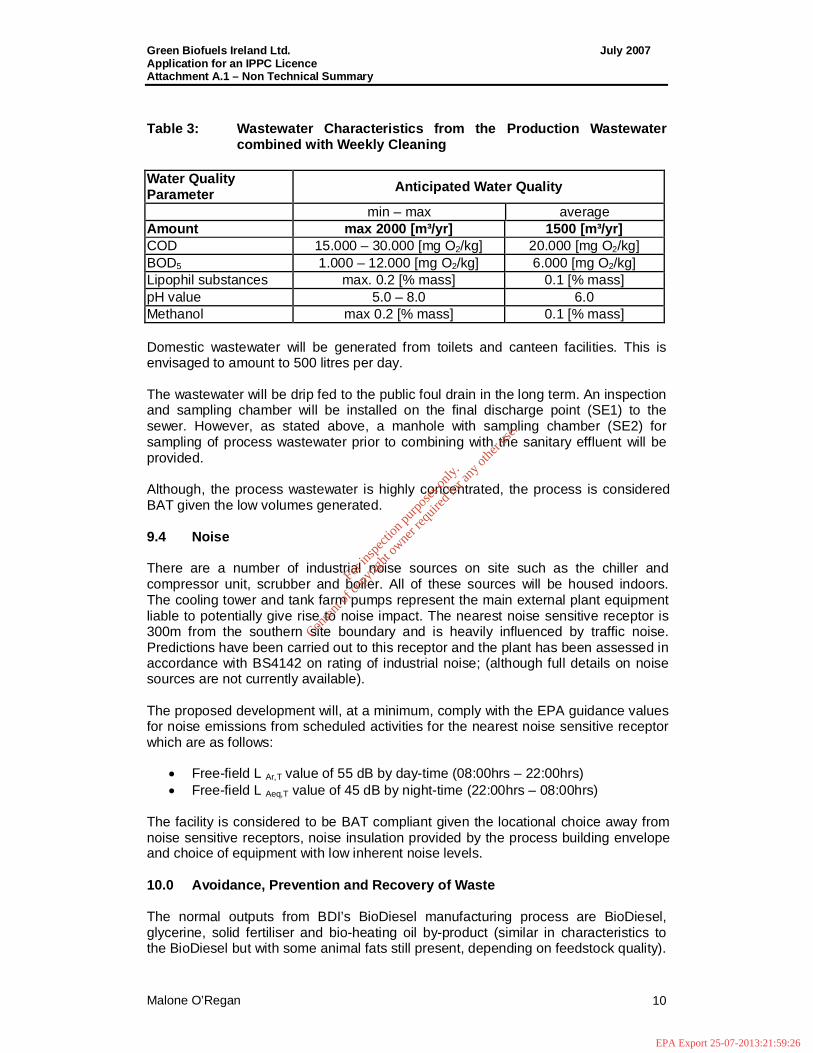
Table 3: Wastewater Characteristics from the Produc tion Wastewater combined with Weekly Cleaning
Water Quality Parameter Anticipated Water Quality
min – max average Amount max 2000 [m³/yr] 1500 [m³/yr] COD 15.000 – 30.000 [mg O2/kg] 20.000 [mg O2/kg] BOD5 1.000 – 12.000 [mg O2/kg] 6.000 [mg O2/kg] Lipophil substances max. 0.2 [% mass] 0.1 [% mass] pH value 5.0 – 8.0 6.0 Methanol max 0.2 [% mass] 0.1 [% mass] Domestic wastewater will be generated from toilets and canteen facilities. This is envisaged to amount to 500 litres per day. The wastewater will be drip fed to the public foul drain in the long term. An inspection and sampling chamber will be installed on the final discharge point (SE1) to the sewer. However, as stated above, a manhole with sampling chamber (SE2) for sampling of process wastewater prior to combining with the sanitary effluent will be provided. Although, the process wastewater is highly concentrated, the process is considered BAT given the low volumes generated. 9.4 Noise There are a number of industrial noise sources on site such as the chiller and compressor unit, scrubber and boiler. All of these sources will be housed indoors. The cooling tower and tank farm pumps represent the main external plant equipment liable to potentially give rise to noise impact. The nearest noise sensitive receptor is 300m from the southern site boundary and is heavily influenced by traffic noise. Predictions have been carried out to this receptor and the plant has been assessed in accordance with BS4142 on rating of industrial noise; (although full details on noise sources are not currently available). The proposed development will, at a minimum, comply with the EPA guidance values for noise emissions from scheduled activities for the nearest noise sensitive receptor which are as follows:
• Free-field L Ar,T value of 55 dB by day-time (08:00hrs – 22:00hrs) • Free-field L Aeq,T value of 45 dB by night-time (22:00hrs – 08:00hrs)
The facility is considered to be BAT compliant given the locational choice away from noise sensitive receptors, noise insulation provided by the process building envelope and choice of equipment with low inherent noise levels. 10.0 Avoidance, Prevention and Recovery of Waste The normal outputs from BDI’s BioDiesel manufacturing process are BioDiesel, glycerine, solid fertiliser and bio-heating oil by-product (similar in characteristics to the BioDiesel but with some animal fats still present, depending on feedstock quality).
For
insp
ectio
n pur
pose
s only
.
Conse
nt of
copy
right
owne
r req
uired
for a
ny ot
her u
se.
EPA Export 25-07-2013:21:59:26
Green Biofuels Ireland Ltd. July 2007 Application for an IPPC Licence Attachment A.1 – Non Technical Summary
Malone O’Regan 11
The bio-heating oil is suitable as a saleable biofuel for boilers but would not be of the appropriate standard for vehicles. In general there will be no process waste generated, intermediary by-products and ancillary chemicals such as methanol, alkali, impurities in the product and by-products and excess fatty acids generated during production will be recycled back into the process. The main waste from the production process will be KOH raw material bags and these will be returned to the supplier. Waste will arise from auxiliary processes as follows:
• Laboratory waste • Waste mineral oils from machine lubrication • Interceptor waste • Paper, cardboard plastic and general office waste • Canteen waste • K2SO4 filters • Deionisation concentrate • Ion exchange resin • Waste rags and gloves • Metals from maintenance • Potential fluid waste from tank maintenance and repair
As described above, the process is very efficient and wastes generated are mainly non-hazardous. It is difficult to put exact estimates on quantities likely to be generated at this stage however, it is expected to be less than approximately 8 tonnes per year. Waste generated will be recovered or recycled in most instances except for laboratory waste arisings, liquid organic and inorganic waste from maintenance activities and domestic waste from the canteen which will be disposed of. All waste receptacles will be clearly labelled and will be designed to prevent escape of solids or liquids, waste auditing will be carried out and incompatible wastes will be segregated. All waste contractors will be either licensed by the EPA or permitted by the local authority to handle the waste. As part of its drive to continually improve environmental performance, GBI will keep accurate records of all waste arisings and disposal arrangements. This information will be provided annually to the EPA in the Annual Environmental Report. The facility is considered to be BAT compliant with regard to waste management. 11.0 Energy Efficiency The biodiesel production process has been designed to minimize energy use and makes use of all opportunities to capture and reuse energy particularly in terms of heat. GBI will be commissioning a new facility with new plant and equipment, and the energy efficiency of all equipment will be taken into account by GBI prior to any purchases, thus optimizing energy usage. Nothwithstanding this, once the plant is operational under normal conditions, then the company will monitor energy usage throughout the installation and will identify potential opportunities for improvement in energy efficiency.
For
insp
ectio
n pur
pose
s only
.
Conse
nt of
copy
right
owne
r req
uired
for a
ny ot
her u
se.
EPA Export 25-07-2013:21:59:26
Green Biofuels Ireland Ltd. July 2007 Application for an IPPC Licence Attachment A.1 – Non Technical Summary
Malone O’Regan 12
Insofar as the provision of energy is concerned, GBI has elected to use mains electricity and for the boiler the bio-heating oil by-product mixed with gas oil will be used. The biodiesel manufacturing process is continuous and most stages operate at ambient pressure and relatively low temperatures; - all of which reduce energy needs. Auxiliary systems such as hot water/steam and cooling/chilling units are closed systems as far as possible with heat exchangers to maximize heat usage through the plant. 12.0 Accidents and their Consequences Installation hazards have been assessed according to probability and consequences. Risk management measures and emergency response actions have been developed on this basis. Hazards have been classified as low, moderate or high. No potential hazards have been identified as high risk. The design of the plant is considered to be in accordance with BAT for the minimisation of potential accidents and resulting impacts. GBI has recognised the potential for accidental spills to occur and in particular in relation to potentially polluting materials such as methanol, fuel oil, acid etc. In light of this the primary focus has been to provide management handling and storage procedures that, in the event of a release will prevent the material from escaping to either the drainage system or unsurfaced ground. This will be effected by the provision of secondary containment and bunding for all material that could spill and cause pollution incidents and by ensuring that all movements around the site, will be purpose built contained structures. If in the unlikely event that spills entered the drainage system then these would be contained on site within the surface water attenuation tanks. Continuous monitoring and automatic shutdown valves have been provided on the final discharge point. Major potential accident scenarios are those associated with explosion and fire, given the use of methanol within the process. The installation will have a number of designated fire protection zones and a comprehensive fire protection system. In terms of emergency response provision, GBI will have a site wide emergency response programme which will include detailed response actions and reporting levels for various incidents. All incidents or near misses will be investigated and documented. The Safety Management System and Environmental Management System will be closely linked to ensure that are no contradictory instructions or procedures. Specific procedures and response plans will facilitate the prevention or minimisation of pollution arising from incidents such as spillages, pollution control equipment or plant failure, fires etc. GBI will ensure that all areas where potentially polluting material is stored or handled are regularly inspected and that these inspections are documented. The opportunity for any major or significant incidents at the facility to occur has been minimised, given all of the anti-malfunction systems that have been designed into the installation, and the management practises that will be adopted. The most likely non-conformances i.e. incidents that could be environmentally significant if they do occur are likely to be transient issues and not long term environmental impairment issues. The biodiesel installation does not pose a significant threat to the environment under either normal or abnormal and emergency operating conditions. In the unlikely event of a fire or explosion occurring, the facility has been designed to
For
insp
ectio
n pur
pose
s only
.
Conse
nt of
copy
right
owne
r req
uired
for a
ny ot
her u
se.
EPA Export 25-07-2013:21:59:26
Green Biofuels Ireland Ltd. July 2007 Application for an IPPC Licence Attachment A.1 – Non Technical Summary
Malone O’Regan 13
contain firewater. The firewater retention capacity on site has been determined in accordance with the Fire-Water Retention Facilities (Draft) Guidance Note to Industry on the Requirements for Firewater Retention Facilities published by the EPA. 13.0 Monitoring GBI will routinely monitor emissions and discharges from the installation. This will include the following:
• Methanol and total organic compounds (TOC) from the point source emission stack on a periodic basis as instructed by the EPA.
• NOx and SOx from the boiler stack on a periodic basis as instructed by the EPA.
• Monitoring of boiler efficiency in accordance with the manufacturers instructions.
• BOD, COD, F/O/G pH and methanol monitoring on the emissions to sewer on a periodic basis as required by Wexford County Council.
• Continuous flow monitoring (with pump rates) on emissions to sewer. • Continuous monitoring of pH and TOC on the emissions to surface water. • BOD, F/O/G, petroleum hydrocarbons, suspended solids and temperature on
emissions to surface water on a periodic basis. • Noise monitoring at the boundary and nearest noise sensitive location on a
periodic basis. • Olfactory (sniff) assessment of odours will be carried out daily. • Visual inspections of bunds will be carried out weekly.
Waste, energy and water consumption will also be monitored and recorded on a regular basis, so that trends can be identified and efficiencies adopted, where possible. Specifically, a waste register will be set up. 14.0 Decommissioning Plans GBI has prepared an outline Residuals Management Plan (RMP) which requires that the company upon definitive cessation of activities at the installation decommission to plant in phases such as production cessation, return raw materials to suppliers, sell on final product, dispose of wastes generated, clean down of production and storage areas and pipelines, carry out drain cleaning and surveying, decommission site services and audit and validate all activities. A soil and groundwater investigation will also form part of the RMP. Comparison with the initial site conditions will be made and any surface contamination will be addressed and the arisings disposed of. Any ground or groundwater contamination associated with the installation will be remediated. However given that the avoidance of environmental impact has been a major consideration in the design and operation of the installation, it is considered unlikely that any such contamination will occur.
For
insp
ectio
n pur
pose
s only
.
Conse
nt of
copy
right
owne
r req
uired
for a
ny ot
her u
se.
EPA Export 25-07-2013:21:59:26

(Regional map)
For
insp
ectio
n pur
pose
s only
.
Conse
nt of
copy
right
owne
r req
uired
for a
ny ot
her u
se.
EPA Export 25-07-2013:21:59:26

For
insp
ectio
n pur
pose
s only
.
Conse
nt of
copy
right
owne
r req
uired
for a
ny ot
her u
se.
EPA Export 25-07-2013:21:59:26
For
insp
ectio
n pur
pose
s only
.
Conse
nt of
copy
right
owne
r req
uired
for a
ny ot
her u
se.
EPA Export 25-07-2013:21:59:26
Green Biofuels Ireland Ltd. July 2007 Application for an IPPC Licence Attachment A.1 – Non Technical Summary
__________________________________________________________________________ Malone O’Regan
Green Biofuels Ireland Ltd. Application for an
IPPC Licence
Appendix A.1.1
Conceptual Layout and Photo of Scottish Plant
For
insp
ectio
n pur
pose
s only
.
Conse
nt of
copy
right
owne
r req
uired
for a
ny ot
her u
se.
EPA Export 25-07-2013:21:59:26

For
insp
ectio
n pur
pose
s only
.
Conse
nt of
copy
right
owne
r req
uired
for a
ny ot
her u
se.
EPA Export 25-07-2013:21:59:26
For
insp
ectio
n pur
pose
s only
.
Conse
nt of
copy
right
owne
r req
uired
for a
ny ot
her u
se.
EPA Export 25-07-2013:21:59:26

Green Biofuels Ireland Ltd. July 2007 Application for an IPPC Licence Attachment A.1 Non Technical Summary
__________________________________________________________________________ Malone O’Regan
Green Biofuels Ireland Ltd. Application for an
IPPC Licence
Appendix A.1.2
Block Diagram of Input, Outputs and Emissions
For
insp
ectio
n pur
pose
s only
.
Conse
nt of
copy
right
owne
r req
uired
for a
ny ot
her u
se.
EPA Export 25-07-2013:21:59:26
For
insp
ectio
n pur
pose
s only
.
Conse
nt of
copy
right
owne
r req
uired
for a
ny ot
her u
se.
EPA Export 25-07-2013:21:59:26
GBI BioDiesel Plant -Marshmeadows, New Ross Stream numbers
VTU Engineering
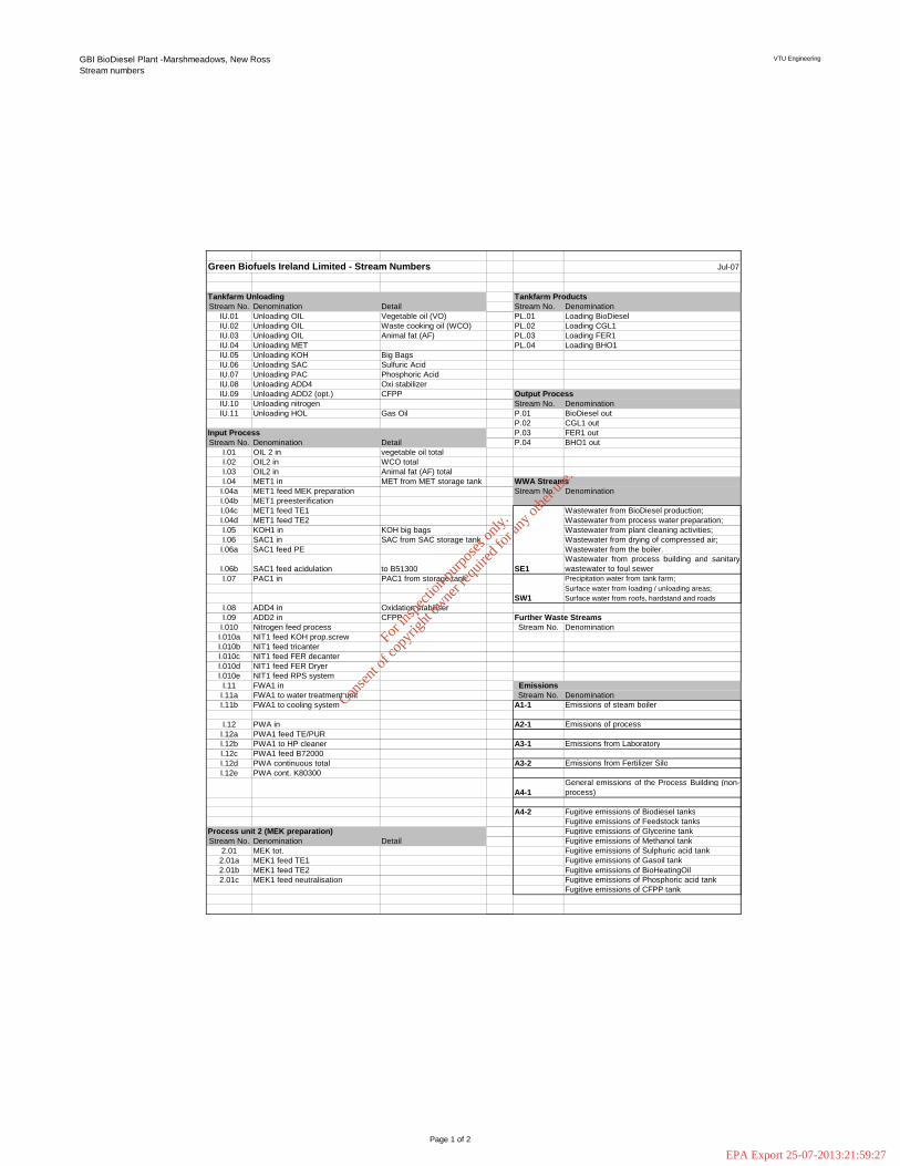
Green Biofuels Ireland Limited - Stream Numbers Jul-07
Stream No. Denomination Detail Stream No. DenominationIU.01 Unloading OIL Vegetable oil (VO) PL.01 Loading BioDieselIU.02 Unloading OIL Waste cooking oil (WCO) PL.02 Loading CGL1IU.03 Unloading OIL Animal fat (AF) PL.03 Loading FER1IU.04 Unloading MET PL.04 Loading BHO1IU.05 Unloading KOH Big BagsIU.06 Unloading SAC Sulfuric AcidIU.07 Unloading PAC Phosphoric AcidIU.08 Unloading ADD4 Oxi stabilizerIU.09 Unloading ADD2 (opt.) CFPPIU.10 Unloading nitrogen Stream No. DenominationIU.11 Unloading HOL Gas Oil P.01 BioDiesel out
P.02 CGL1 outP.03 FER1 out
Stream No. Denomination Detail P.04 BHO1 outI.01 OIL 2 in vegetable oil totalI.02 OIL2 in WCO totalI.03 OIL2 in Animal fat (AF) totalI.04 MET1 in MET from MET storage tank WWA Streams
I.04a MET1 feed MEK preparation Stream No. DenominationI.04b MET1 preesterificationI.04c MET1 feed TE1 Wastewater from BioDiesel production; I.04d MET1 feed TE2 Wastewater from process water preparation;I.05 KOH1 in KOH big bags Wastewater from plant cleaning activities;I.06 SAC1 in SAC from SAC storage tank Wastewater from drying of compressed air;
I.06a SAC1 feed PE Wastewater from the boiler.
I.06b SAC1 feed acidulation to B51300 SE1Wastewater from process building and sanitarywastewater to foul sewer
I.07 PAC1 in PAC1 from storage tank Precipitation water from tank farm; Surface water from loading / unloading areas; Surface water from roofs, hardstand and roads
I.08 ADD4 in Oxidation stabiliserI.09 ADD2 in CFPP
I.010 Nitrogen feed process Stream No. DenominationI.010a NIT1 feed KOH prop.screwI.010b NIT1 feed tricanterI.010c NIT1 feed FER decanterI.010d NIT1 feed FER DryerI.010e NIT1 feed RPS system
I.11 FWA1 in EmissionsI.11a FWA1 to water treatment unit Stream No. DenominationI.11b FWA1 to cooling system A1-1 Emissions of steam boiler
I.12 PWA in A2-1 Emissions of processI.12a PWA1 feed TE/PURI.12b PWA1 to HP cleaner A3-1 Emissions from LaboratoryI.12c PWA1 feed B72000I.12d PWA continuous total A3-2 Emissions from Fertilizer SiloI.12e PWA cont. K80300
A4-1General emissions of the Process Building (non-process)
A4-2 Fugitive emissions of Biodiesel tanksFugitive emissions of Feedstock tanksFugitive emissions of Glycerine tank
Stream No. Denomination Detail Fugitive emissions of Methanol tank2.01 MEK tot. Fugitive emissions of Sulphuric acid tank2.01a MEK1 feed TE1 Fugitive emissions of Gasoil tank2.01b MEK1 feed TE2 Fugitive emissions of BioHeatingOil2.01c MEK1 feed neutralisation Fugitive emissions of Phosphoric acid tank
Fugitive emissions of CFPP tank
Further Waste Streams
Process unit 2 (MEK preparation)
SW1
Tankfarm Unloading
Input Process
Tankfarm Products
Output Process
Page 1 of 2
For
insp
ectio
n pur
pose
s only
.
Conse
nt of
copy
right
owne
r req
uired
for a
ny ot
her u
se.
EPA Export 25-07-2013:21:59:27

GBI BioDiesel Plant -Marshmeadows, New Ross Stream numbers
VTU Engineering
Monitoring PointsStream No. Denomination Detail
1.01 OIL3 feed TE1.02 WPH1 to B50900 SE2 Wastewater
SW1 Surface waterStream No. Denomination Detail2.02 FME1 TE1 after 1st stage TE A1-1 Atmosphere2.03 GLP1 discharge TE1 after 1st stage TE A2-12.04 FME1 TE2 after 2nd stage TE2.05 GLP1 discharge TE2 after 2nd stage TE AN1 Noise2.06 FME1 PUR1 after 1st stage purification AN22.07 WPH2 PUR1 after 1st stage purification2.08 FME2 PUR2 after 2nd stage purification2.09 WPH2 PUR2 after 2nd stage purification Abbreviations explained2.09a WPH2 feed WPH buffer/PUR2 recirculation B220002.09b WPH2 feed GLP collector B50100 AIR 1 Compressed air2.10 FME2 PUR3 after 3rd stage purification ADD 1 Additive (CFPP)2.11 WPH2 PUR3 after 3rd stage purification ADD 2 Additive (CFPP) 2.11a WPH2 feed WPH buffer/PUR3 ADD 3 Additive (oxidation stability)2.11b WPH2 feed PUR2 to purification 2nd stage ADD 4 Additive (oxidation stability)2.11c WPH2 discharge GLP collector BHO 1 Bio heating oil 2.11d WPH2 feed TE2 to TE 2nd stage CAP 1 Caustic Pottash2.11e WPH2 feed PUR1 to purification 1st stage CAS 1 Caustic Soda, Sodium Hydroxide
CGL 1 Crude glycerineCGL 2 Crude glycerine COL, COH 1 Condensate
Stream No. Denomination Detail CWA 1 Cooling water 4.01 FME2 discharge FME flash to FME-Distillation column CWP 1 Cooling water 4.02 FCO1 discharge FME flash to TE DCP 1 Distillation CoProduct
DRS 1 Distillation residue FCO 1 Volatile component FER 1 Potassium sulphate phase 2 FER 2 Potassium sulphate
Stream No. Denomination Detail FFA 1 Free fatty acids 5.01 GLP1 feed acidulation from GLP collector FFA 2 Free fatty acids 5.02 FME1 feed TE from skimmer in B51000 FME 1 Methylester 5.03 GLP2 feed neutralisation from tricanter FME 2 Methylester 5.04 FFA1 discharge tricanter FME 3 BioDiesel 5.05 FER1 feed FER buffer tank FER discharge from tricanter FWA 1 Fresh water
GAS 1 Natural gasGLP 1 Glycerine phase
Process unit 6 (FER recovery, FER drying, Neutralisation) GLP 2 Glycerine phase Stream No. Denomination Detail GLP 3 Glycerine phase
6.01 GLP2 discharge neutralisation GLP 4 Glycerine phase 6.02 GLP2 feed GLP demeth column GFF 1 Three-Media-Mixture 6.03 SALT discharge GLP filter HTM 1 Heat transfer Medium 6.04 FER1 after decanter HWA 1 Hot water 6.05 FFA from decanter HOL 1 Heating oil 6.06 MET from FER dryer KOH 1 Potassium hydroxide
MEG 1 MonoethylenglycolProcess unit 7 (Demethanolisation, Dewatering) MEK 1 Potassium methanolate Stream No. Denomination Detail MET 1 Methanol
7.01 CGL2 discharge GLP demeth col. MET 2 Methanol7.02 MET2 discharge GLP demeth col. MET 3 Methanol -Water 7.02a MET2 to Preesterification MET 4 Methanol -Methylester -Water 7.02b MET2 to MEK preparation MOD 1 Mineral oil diesel7.02c MET2 to NITWGS NIT 1 Nitrogen 7.02d MET2 to Tricanter NOH 1 Caustic Soda, Sodium Hydroxide7.03 CGL2 feed dewatering column OIL 1 Fats and Oils 7.04 FFA from skimm. MET buffer tank OIL 2 Fats and Oils 7.05 RWA from dewatering column OIL 3 Fats and Oils 7.05a RWA to transesterification PAC 1 Phosphoric acid 7.05b RWA to FME purification-1 PAC 2 Phosphoric acid 7.05c RWA to NITWGS1 PWA 1 Process water
PWA 2 Process waterProcess unit 8 (ventilation system) RPS 1 Ventilation gas Stream No. Denomination Detail RWA 1 Recylcing water
8.01 VEN1 to W80200 SAC 1 Sulfuric acid8.02 VEN1 discharge W80200 SAC 2 Sulfuric acid 8.03 MET/H2O from W80200 SAC 3 Sulfuric acid8.04 MET/H2O from K80300/to PUR3 STL, STH 1 Steam
STL 2 Steam VEN 1 Ventilation gasWGS 1 Waste gasWPH 1 Aqueous phase WPH 2 Aqueous phaseWWA 1 Waste water
Process unit 5 (GLP collection, acidulation, phase separation)
Process unit 2 (transesterification)
Process unit 4 (FME distillation)
Process unit 1 (preesterification)
Page 2 of 2
For
insp
ectio
n pur
pose
s only
.
Conse
nt of
copy
right
owne
r req
uired
for a
ny ot
her u
se.
EPA Export 25-07-2013:21:59:27