
Apollo 1500/1600 Swing Gate Operator · The Apollo Model 1500/1600 Swing Gate Operator is designed...
26
Nice Apollo Swing Gate Opener Model 1500 Model 1600 Vehicular Swing Gate Opener Revision 1.0.0.0_2-2014
Transcript of Apollo 1500/1600 Swing Gate Operator · The Apollo Model 1500/1600 Swing Gate Operator is designed...

Nice Apollo Swing Gate Opener Model 1500
Model 1600Vehicular Swing Gate Opener
Revision 1.0.0.0_2-2014

EXTREMELY IMPORTANT 2
TECHNICAL SPECIFICATIONS 2
1 - OVERVIEW 2
2 - GATE INFORMATION 2
2.1 - ASTM F2200 2
2.2 - Gate latches 3
2.3 - Specific applications 3
2.4 - Swing gates 3
2.5 - General requirements 3
3 - SAFETY AND CAUTIONS 3
3.1 - Properly installed safety devices 3
3.2 - Safety signs, notices to personnel warning signs 3
3.3 - Gate system safety devices 4
3.4 - Infrared beams and warning signs 4
3.5 - Establish the location 4
3.6 - Read and follow all instructions 4
3.7 - Keep children away 4
3.8 - Test the gate system 4
3.9 - Keep gates properly maintained 4
4 - INSTALLATION NOTES 5
5 - APPLICATIONS 7
6 - SOLAR PANEL CHART 7
7 - PARTS IDENTIFICATION 8
8 - PULL TO OPEN INSTALLATION 9
8.1 - Location of pivot point 9
8.2 - Vertical position of pivot arm 9
9 - PUSH TO OPEN INSTALLATION 10
9.1 - Location of pivot point 10
9.2 - Vertical position of pivot arm 10
9.3 - Wiring Actuators for push to open 10
10 - ACTUATOR MOUNTING 11
11 - CONTROL BOX MOUNTING 11
12 - CONNECTING ACTUATORS 11
13 - GATE BRACKET MOUNTING 12
14 - LIMIT SWITCH ADJUSTMENT 12
14.1 - Model 1500 12
14.2 - Model 1600 12
15 - CONTROL BOARD CONNECTIONS 13
16 - CONTROL BOARD ADJUSTMENTS 14
17 - NICE RECEIVERS & TRANSMITTERS 15
17.1 - Wiring the Nice receiver 15
17.2 - Programming transmitters 15
18 - GENERAL LAYOUT & SAFETY ACCESS 16
20 - MAINTENANCE SCHEDULE 18
21 - TROUBLESHOOTING 17
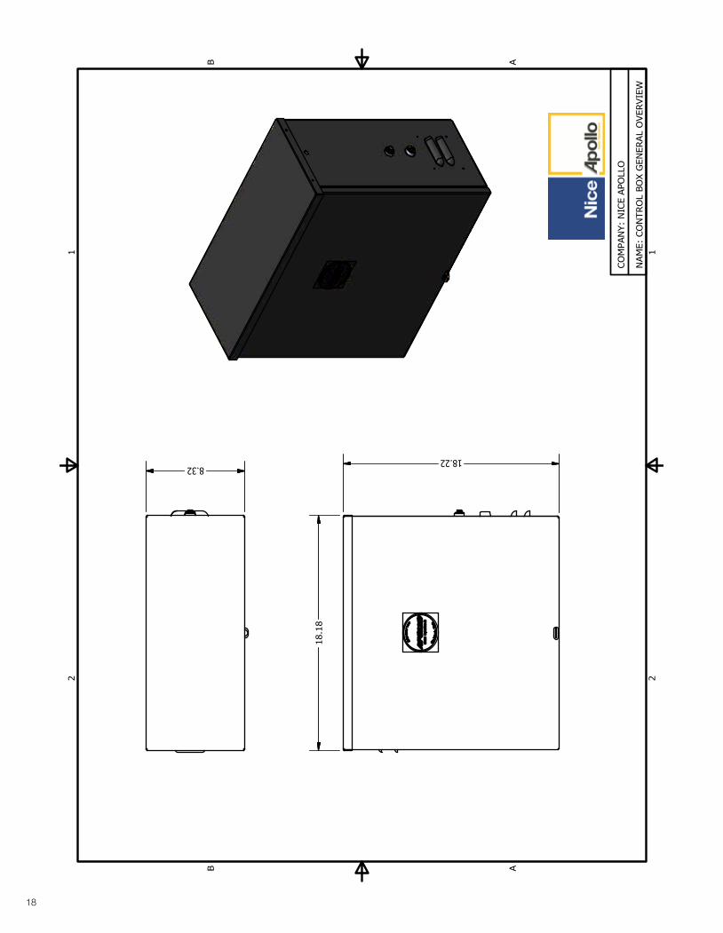
22 - OPERATOR DIMENSIONS
22.1 - Control box 18
22.2 - Actuator 19
23 - EXPLODED VIEWS
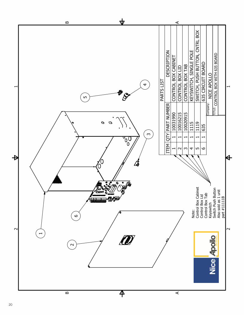
23.1 - 1500 Single gate control box 20
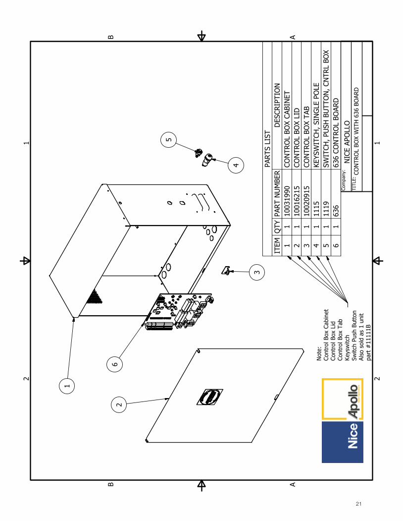
23.2 - 1600 Dual gate control box 21
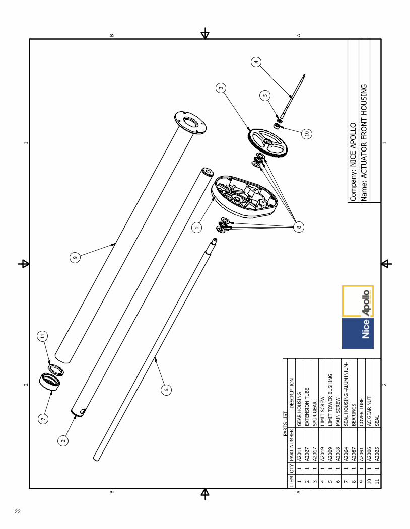
23.3 - Actuator front 22
23.4 - Actuator back 23
24 - WARRANTY INFORMATION 24
25 - INSTALLATION CHECKLIST 25
TABLE OF CONTENTS
3
1 - OVERVIEW
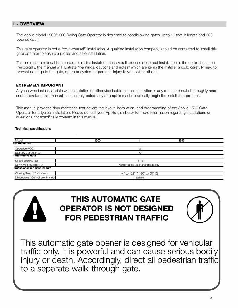
THIS AUTOMATIC GATE OPERATOR IS NOT DESIGNED
FOR PEDESTRIAN TRAFFIC
This automatic gate opener is designed for vehicular traffic only. It is powerful and can cause serious bodily injury or death. Accordingly, direct all pedestrian traffic to a separate walk-through gate.
The Apollo Model 1500/1600 Swing Gate Operator is designed to handle swing gates up to 16 feet in length and 600 pounds each.
This gate operator is not a “do-it-yourself” installation. A qualified installation company should be contacted to install this gate operator to ensure a proper and safe installation.
This instruction manual is intended to aid the installer in the overall process of correct installation at the desired location. Periodically, the manual will illustrate “warnings, cautions and notes” which are items the installer should carefully read to prevent damage to the gate, operator system or personal injury to yourself or others.
EXTREMELY IMPORTANT Anyone who installs, assists with installation or otherwise facilitates the installation in any manner should thoroughly read and understand this manual in its entirety before any attempt is made to actually begin the installation process.
This manual provides documentation that covers the layout, installation, and programming of the Apollo 1500 Gate Operator for a typical installation. Please consult your Apollo distributor for more information regarding installations or questions not specifically covered in this manual.
Technical specifications
Electrical data
Performance data
Dimensional and general data
Model 1500 1600
Operation (VDC) 12Standby Current (mA) 10
Speed open 90° (s) 14-16Duty Cycle (cycles/hour) Varies based on charging capacity
Working Temp (°F Min/Max) -4º to 122º F (-20º to 50º C)Dimensions - Control box (inches) 18x18x8
4
3 - SAFETY AND CAUTIONS
WARNING
2 - GATE INFORMATION • Loops and loop detectors, photo-cells or other equivalent devices must be installed with this gate operator to prevent the gate from closing on vehicular traffic
• The speed limit for vehicular traffic through the gate area is 5 MPH. Install speed bumps and signs to keep vehicular traffic from speeding through the gate area. Failure to adhere to posted speed limits can result in damage to the gate, operator, and to the vehicle.
• Be sure that all residents are familiar with the proper use of the gate and gate operator. Be sure that all residents are familiar with the possible hazards associated with the gate system.
• Be sure that all warning signs are permanently installed on both sides of the gate in an area where they are fully visible to traffic
• It is your responsibility to periodically check all reversing devices. If any of these devices are observed to function improperly, remove the operator from service immediately and contact your installing or servicing dealer.
• Follow the recommended maintenance schedule of one inspection per every 180 days of use.
• Do not allow children to play in the area of the operator or to play with any gate-operating device.
• Be sure that all activating devices are installed a minimum distance of 8 feet away from the gate and gate operator, or in such a way that a person cannot touch the gate or gate operator while using the activating device. If activating devices are installed in violation of these restrictions, immediately remove the gate operator from service and contact your installing dealer.
• To remove the gate operator from service, operate the gate to the full open position, shut off power to the operator at the service panel (if applicable), and disconnect batteries.
2.1 - ASTM F2200 Gates shall be constructed in accordance with the provisions given for the appropriate gate type listed, refer to ASTM F2200 for additional gate types. Protrusions shall not be permitted on any gate, refer to ASTM F2200 for exceptions, if any. Any non-automated gate that is to be automated in any manner should be upgraded to conform to the provisions contained within the provisions of this document and ASTM F2200 as applicable.
2.2 - Gate latches In association with this gate controller and these swing gate operators, at no time should manual gate latches or locks be used. The forces applied to a swing gate operator could be in excess of those forces which are safe for bystanders. Should unnecessary forces be applied to a gate system which is in the locked position, the catastrophic failure of the gate or locking mechanism could result in substantial damage, extensive physical injury and or death.
2.3 - Specific applications This swing gate operators are intended for those locations where vehicle traffic is intended to be controlled through the use of an entryway obstruction (gate). The gate system should be made of closed material types which prevent any body part from entering, becoming entangled or otherwise entering the gate in any manner. If the gate is not fully closed off from access, the opening or closing of the gate system may result in severe damage, injury or death.
2.4 - Swing and slide gates Swing and slide gates are designed to move across an entry control point to prevent or allow controlled access by authorized persons or equipment. Swing or slide gate systems are not necessarily completely autonomous systems, and require regular maintenance and inspection on a periodic schedule. Although with certain safety devices in place the gate system could operate as a completely independent system free from human interaction for a defined period of time, human inspection and testing is required to ensure longevity and safe operation over long periods of time.
2.5 - General requirements
• Safety and security are obviously a number one priority for both the manufacturer and the end user. As a result this manual has been written to make all persons fully aware of the responsibilities required to ensure constant safety, security and longevity are acquired throughout the life of the system.
• The manufacturer of this swing gate system has performed countless hours of testing, analysis and statistical control analysis to ensure that this operator performs its intended function for extended periods of time. The installer should ensure and verify that all required safety devices are installed correctly and in a manner consistent with the requirements of this manual. Additionally, all devices, security devices, safety devices, sensors and other affiliated attachments are installed in a robust manner that will prevent their accidental damage, removal or incidental tampering.
• A basic requirement for this system to operate correctly is that at any time a sensor is triggered, covered, disconnected or otherwise tampered with, that the entire system ceases to function. If any part of the gate safety system is removed or triggered, an immediate safety action by the gate operator is expected (retraction or stoppage). If the gate safety system is not functional, or fails to operate within these guidelines, the gate should be immediately removed from service until repairs can be made.
• Any gate system that is open or has slats, bars or other material which allows an individual to stick their hands, head, or feet through the material, must be converted or covered in such a manner so as to prevent such future actions. Application of materials, and how to modify the gate system is up to the end user or installer, however care should be taken to prevent such human interaction into the moving gate system. No entry into the gate is ever authorized and should be prevented by whatever measures are required for that specific installation. Care should always be used during installation!
IMPORTANT SAFETY INSTRUCTIONS
WARNING - TO REDUCE THE RISK OF INJURY OR DEATH READ AND FOLLOW ALL INSTRUCTIONS.
• Never let children operate or play with gate controls. Keep the remote control away from children.
• Always keep people and objects away from gate. NO ONE SHOULD CROSS THE PATH OF THE MOVING GATE.
• Test the operator periodically. The gate MUST reverse on contact with a rigid object or stop or reverse when an object activates the non-contact sensors. After adjusting the force or the limit of travel, retest the gate operator. Failure to adjust and retest the gate operator properly can increase the risk of injury or death.
• Use the emergency release only when the gate is not moving. • KEEP GATES PROPERLY MAINTAINED. Read the owner’s manual. Have
a qualified service person make repairs to gate hardware. • The entrance is for vehicles only. Pedestrians must use separate entrance. • SAVE THESE INSTRUCTIONS!
3.1 - Properly installed safety devices Safety devices are used to sense, register and prevent damage to vehicular traffic which may block the path of the gate system. If properly installed and inspected for functionality within the prescribed maintenance procedures, the safety devices should prevent the gate system from inflicting harm or damage as a result of its opening and closing action.
3.2 - Safety signs, notices to personnel warning signs Safety signs must alert all who may enter the gate system area, as to the danger posed by moving equipment. Safety features must be installed and work correctly, such as the infrared beam. This safety device prevents serious injury or death as a result of the gate closing while an object or person blocks the gate operating pathway. An optional flashing lamp that is activated anytime the gate is moving should be added in addition to the aforementioned safety features.

5
4 - INSTALLATION NOTES
• A minimum of two (2) WARNING SIGNS shall be installed, one on each side of the gate where easily visible.
• Test all features for proper functions before placing the automatic vehicular gate opener into service.
• Demonstrate the basic functions and safety features of the gate system to owners/end users/general contractors, including how to turn off power and how to operate the manual release feature.
• Leave safety instructions, product literature, installation manual and maintenance instructions with end user.
• Explain to the owners/users the importance of a service contract that includes a routine testing of the entire system including the entrapment protection devices, and explain the need for the owners to insure that this testing is performed routinely.
• Offer the owner/end user a maintenance contract, or contact them regularly to offer maintenance.
• See instructions on the placement of non-contact sensors for each type of application.
4.1 - Follow Instructions Always follow all instructions included in this manual to ensure safety and the longevity of the operator.
4.2 - Intended usage THIS CIRCUIT BOARD IS INTENDED FOR USE WITH VEHICULAR SWING AND SLIDE GATES ONLY.
4.3 - Warnings, cautions and notes 4.3.1 Gate terms “system, “gate operator”, “gate system”, and “gate
operator system” for these warnings, cautions, and notes is intended to cover the gate controller, gate controller software, the gate actuator, and all safety accessories included within a typical installation.
4.3.2 Gate system designers, installers and users must take into consideration the inherent hazards associated with each installation, since no two installations will be exactly alike.
4.3.3 Improperly designed, constructed, installed or maintained systems can and may introduce hazards which may or may not be readily seen or identified by users, bystanders, installers or inspectors
4.3.3 Improperly designed, constructed, installed or maintained systems can and may introduce hazards which may or may not be readily seen or identified by users, bystanders, installers or inspectors
4.3.4 All pinch points must be guarded or eliminated. 4.3.5 Only install this gate system opener in appropriate manners in which
the operation is safe and secure. 4.3.6 A gate operator exerts a great amount of force in order to move
the gate system in normal operation, therefore appropriate safety sensors, measures, notices and appropriate safety features must be incorporated in all installations.
4.3.7 The gate must be installed correctly and no binding or resistance should be present throughout its movement in either direction.
4.3.8 The gate system must be installed in an area and in such a manner in which the gate has sufficient clearance to open, close and move without striking or contacting any structures and/or other obstructions.
4.3.9 The gate system is designed for vehicular traffic only, and should never, under any situation be used for pedestrian traffic
4.3.10 Pedestrian prohibited signs, warning signs or other suitable measures must be used at minimum, to warn pedestrians to stay away from, and to not use this system under any circumstances.
4.3.11 Pedestrians should be encouraged to use a pedestrian entry/exit only. 4.3.12 Pedestrians should never cross the path of a moving gate. The
sensors are designed to prevent contact with a vehicle and are not necessarily capable of preventing contact with a pedestrian. Care should be taken to prevent pedestrian usage under any circumstances.
4.3.13 One or more non-contact sensors must be used in any situation or area where entrapment may have the possibility of occurring.
4.3.14 Gates shall be constructed in accordance with the provisions given for the appropriate gate type listed, refer to ASTM F2200 for additional gate types.
4.3.15 Any existing manual gate latches shall be removed or disabled when an automatic gate system is installed. Use only mag locks controlled by the system
3.3 - Gate system safety devices Automatic gate operators are designed to move a heavy steel gate. Great amounts of force are sometimes used to move these heavy systems. The automatic gate system may cause significant damage or injury if the path of the gate is obstructed. All sensors, safety devices and warning notices must be in place and operable in order for this system to operate properly. It is the installer’s responsibility to install this system properly and to ensure its correct and safe operation.
3.4 - Infrared beams and warning signs Infrared beams are used to inform the control board that an obstruction is present. Safety devices must be installed properly and inspected periodically to ensure continued reliability and safety. Safety devices, safety sensors, warning signs and notices of moving equipment danger must be installed and readily visible by all paths of approach to the gate system. Failure to post warnings could result in loss of life, damage or physical injury.
3.5 - Establish the location The installer of this system needs to establish the location of the opener in accordance with instructions contained within this manual. A typical layout is provided at the end of this manual with a nominal basic drawing. It is the installer’s responsibility to ensure that the opener is installed in such a fashion so as to prevent binding, pinching or improper articulation of the system throughout its actuation cycle.
3.6 - Read and follow all instructions 3.7 - Keep children away Never let children operate or play with gate controls. Keep the remote control away from children.
3.8 - Test the gate system The gate must reverse on contact with a rigid object or stop when an object activates the non-contact sensors. After adjusting the force or the limit of travel, retest the gate operator. Failure to adjust and retest the gate operator properly can increase the risk of injury or death. Test force and correct functionality for photo-eyes and other safety devices at least every 6 months. ONLY USE the MANUAL RELEASE when the gate is not moving or when the unit fails or in case of power outage. • Turn the power to the gate controller OFF AND REMOVE BATTERIES
before using the emergency release.
3.9 - Keep gates properly maintained Have only a qualified service person make repairs. Unqualified service technicians are not recommended.
Before installing and/or operating the gate opener, installers and/or users should do the following: • Confirm the gate operator being installed is appropriate for the application. • Confirm the gate is designed and built according to current applicable
published industry standards. • Confirm all appropriate features and accessory devices are being
incorporated, including both primary and secondary entrapment protection devices.
• Make sure the gate works freely before installing the operator. • Repair or service worn or damaged gate hardware before installing the
operator. • Adjust the FORCE device to the minimum force setting that allows reliable
gate operation. • Install operator inside fence line (DO NOT install operator on public side of
fence line). • Swinging gates shall not open into public access areas. • Install a proper electrical ground to a gate operator. • Install keypad controls where users cannot touch, or reach through gate
while operating controls, which is a minimum of 8 feet from the gate. • Install controls where user has full view of gate operation. • Install all warning signs on both sides of the gate to warn persons in
the area of potential hazards associated with automatic vehicular gate operation.

6
4.3.16 Protrusions shall not be permitted on any gate, refer to ASTM F2200 for exceptions, if any.
4.3.17 Gates shall not be designed, constructed and installed in such a manner that gravity will cause or initiate movement in any direction whether the operator is attached or not.
4.3.18 A pedestrian gate shall not, under any circumstances, be attached to, or incorporated into, any vehicular gate system in manner. This also applies to any fence or wall, or any portion thereof, that the gate may cover in the open or closed position.
4.3.19 Any non-automated gate that is to be automated in any manner should be upgraded to conform to the provisions contained within the provisions of this document and ASTM F2200 as applicable.
4.3.20 To reduce the risk of severe injury or death please read and under stand this entire manual and your local code requirements prior to starting installation. Additionally, understanding the ASTM standards will assist you in the proper assembly, installation and operation of your gate opening system.
4.3.21 Disconnect all electricity and/or all sources of power before performing any maintenance.
4.3.22 To reduce the risks of fire or injury always contact the installer or distributor prior to performing any repairs or maintenance.
4.3.23 Never operate gate with obstructions present. 4.3.24 No one should ever cross the operative path of the gate. 4.3.25 Never let children play or linger in the vicinity of the gate or opener
equipment. 4.3.26 Never operate the gate or the opener when the opener is not
operating or adjusted correctly. 4.3.27 Never allow children to play with or manipulate gate controls. Keep
all remotes away from children. 4.3.28 Only use the MANUAL RELEASE when gate is completely stationary.
Untrained persons should never touch the gate or any releases if any are installed or applicable.
4.3.29 Test the gate operator periodically (once every 6 months minimum). Gate must reverse course or stop immediately upon contact with any source in its path. Gate must stop and reverse course at any time any object or other item crosses the path of the gate. Should the safety sensors not stop and/or reverse the gates travel, immediately investigate and repair the inoperative condition. Gate should not be used under any circumstances, if all sensors and safety devices are not performing to standards illustrated within this manual.
4.3.30 Gate should not be used if safety devices are not performing to all local, state and federal guidelines.
4.3.31 Replace any fuses only with fuse of same type and rating. 4.3.32 Installation of this gate system in a manner inconsistent with the
manufacturer’s recommended instructions, local, State or Federal law transfers the liability unto the installer. Careful consideration has been taken by the manufacturer’s to devise safe measures, safe design and incorporate safety measures to prevent injury, death or property damage. By circumventing, ignoring or modifying any safety system or the exclusion thereof, the installer is creating a new untested process outside the purview of the manufacturer and therefore assumes all risk.
4.3.33 This unit is not to be installed on any gate, door or other structure which serves to block, secure, close off or otherwise control a pedestrian entry point or access point.
4.3.34 Vehicular swing gates shall be designed, constructed and installed in accordance with security related parameters specific to the application in question, with absolute safety in all considerations.
4.3.35 Never mount any device that operates the gate opener where the user can reach around, over or through the gate to operate the controls. Controls should be mounted at minimum, 8 feet away from any moving part of the gate or gate system.
4.3.36 A hard wired control shall be located in such a manner so that electronic communication between the two is never interrupted or the wires damaged.
4.3.37 Any controls used to activate the device should be located within view of the gate and should have safety features that prevent unauthorized use.
4.3.38 Never allow anyone to ride, hang on or otherwise touch the gate.
4.3.39 Safety sensors must be present at all times. The hard wired safety sensors must be arranged and installed in such a manner so that the communication between gate operator and sensor(s) are never interrupted or severed by mechanical damage or movement. All items which have sensors or safety devices installed must be constructed or installed in such a manner so as to prevent removal or damage. All subsequent sensors must be suitable for the system installed and approved for use.
4.3.40 Never increase the force used to move the gate, beyond the absolute minimum required.
4.3.41 Never use force adjustments to compensate for binding, sticking or resistant operation. These situations should be addressed and corrected before installation of the gate operator. Gate systems should swing freely in all directions prior to installation of this gate operator.
4.3.42 After any adjustment is made, all safety modes/features must be tested. Gate must stop or reverse upon any object crossing the path of the gate or the gate comes into contact with any object.
4.3.43 Activate gate only when the gate is in clear view of the user, the gate system is properly adjusted, tested and verified, and there are no obstructions present.
4.3.44 Keep gate and gate system properly maintained and properly inspected at all times.
4.3.45 This operator is intended for installation only on swing gates used to control vehicular traffic
4.3.46 The gate must be installed in a location so that sufficient clearance is provided between the gate and adjacent structures when opening and closing to reduce the risk of entrapment.
4.3.47 The gate must be properly installed and work freely in both directions prior to the installation of the gate operator.
4.3.48 Install the gate operator only when the operator is appropriate for the construction and the usage class of the gate.
4.3.49 The gate must be properly installed and work freely in both directions prior to the installation of the gate operator.
4.3.50 Controls must be far enough from the gate so that the user is prevented from coming in contact with the gate while operating the controls.
4.3.51 All warning signs and placards must be installed where visible in the area of the gate.
4.3.52 Care shall be given to reduce the risk of nuisance tripping such as when a vehicle trips the sensor while the gate is still moving.
4.3.53 Gate operators must utilize a contact sensor such as an edge sensor. 4.3.54 A hardwired contact sensor shall be located and its wiring arranged so
that the communication between the sensor and the gate operator is not subject to mechanical damage.
4.3.55 A wireless contact sensor such as one that transmits radio frequency (RF) signals to the gate operator for entrapment protection functions are recommended.

7
6 - SOLAR PANEL CHART
This Apollo Gate Operator is 12 Volt DC (Direct Current) powered. A 12 Volt sealed battery (33 ampere hour minimum for AC charged systems, 70 ampere hour minimum for solar charged systems) with connecting posts located on the top is recommended.
The following table should be used as a guide for capacity of operation of operators only, additional options may reduce the daily usage.
Please note that the charge capability of solar panels will vary with different geographical locations.
If a trickle charger is used and a standard electrical outlet is not readily available, a licensed electrician will be required for proper electrical hook up.
Daily cycles 1-10 1-20 1-40 1-60 1-80 80+
5 watt solar panel *10 watt solar panel *20 watt solar panel (requires regulator) *30 watt solar panel (requires regulator) *40 watt solar panel (requires regulator) *1.5 amp battery charger *10 amp battery charger *
Note: Double the amount of solar wattage for dual gate operators
8
7 - PARTS IDENTIFICATION
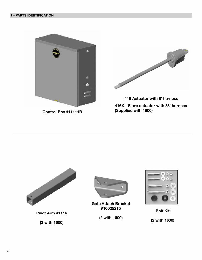
Control Box #11111B
416 Actuator with 8’ harness
416X - Slave actuator with 38’ harness (Supplied with 1600)
Pivot Arm #1116
(2 with 1600)
Gate Attach Bracket #10025215
(2 with 1600)
Bolt Kit
(2 with 1600)
9
8 - PULL TO OPEN INSTALLATION
IMPORTANT - Never weld parts to the gate or posts when the operator circuit board is powered. Doing so may damage the board beyond repair.
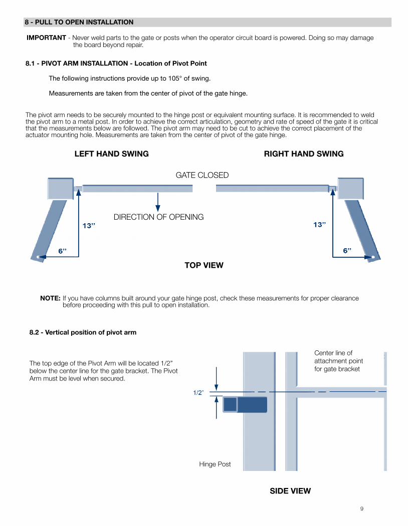
8.1 - PIVOT ARM INSTALLATION - Location of Pivot Point
The following instructions provide up to 105° of swing.
Measurements are taken from the center of pivot of the gate hinge.
The pivot arm needs to be securely mounted to the hinge post or equivalent mounting surface. It is recommended to weld the pivot arm to a metal post. In order to achieve the correct articulation, geometry and rate of speed of the gate it is critical that the measurements below are followed. The pivot arm may need to be cut to achieve the correct placement of the actuator mounting hole. Measurements are taken from the center of pivot of the gate hinge.
NOTE: If you have columns built around your gate hinge post, check these measurements for proper clearance before proceeding with this pull to open installation.
8.2 - Vertical position of pivot arm
LEFT HAND SWING RIGHT HAND SWING
GATE CLOSED
DIRECTION OF OPENING
TOP VIEW
Center line of attachment point for gate bracket
Hinge Post
SIDE VIEW
The top edge of the Pivot Arm will be located 1/2” below the center line for the gate bracket. The Pivot Arm must be level when secured.
10
9 - PUSH TO OPEN INSTALLATION
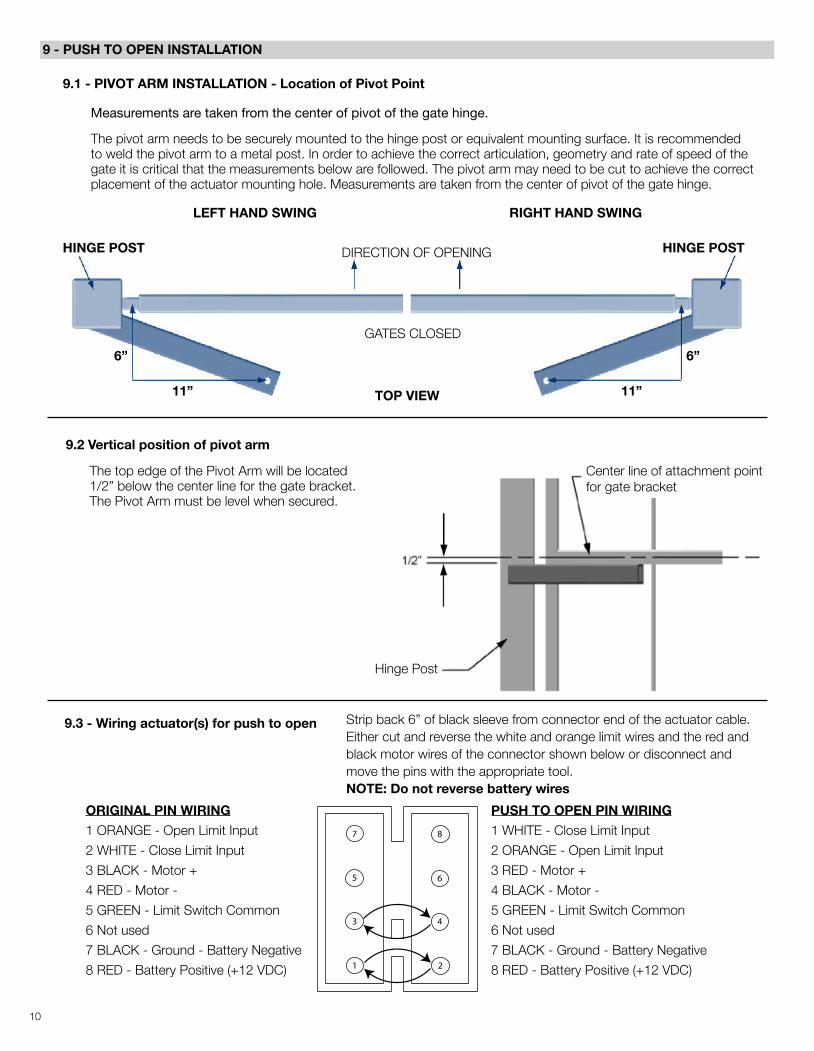
9.1 - PIVOT ARM INSTALLATION - Location of Pivot Point
Measurements are taken from the center of pivot of the gate hinge.
The pivot arm needs to be securely mounted to the hinge post or equivalent mounting surface. It is recommended to weld the pivot arm to a metal post. In order to achieve the correct articulation, geometry and rate of speed of the gate it is critical that the measurements below are followed. The pivot arm may need to be cut to achieve the correct placement of the actuator mounting hole. Measurements are taken from the center of pivot of the gate hinge.
Strip back 6” of black sleeve from connector end of the actuator cable. Either cut and reverse the white and orange limit wires and the red and black motor wires of the connector shown below or disconnect and move the pins with the appropriate tool.NOTE: Do not reverse battery wires
DIRECTION OF OPENING
GATES CLOSED
HINGE POST HINGE POST
LEFT HAND SWING RIGHT HAND SWING
TOP VIEW
6”
11”
6”
11”
The top edge of the Pivot Arm will be located 1/2” below the center line for the gate bracket. The Pivot Arm must be level when secured.
Hinge Post
Center line of attachment point for gate bracket
ORIGINAL PIN WIRING1 ORANGE - Open Limit Input
2 WHITE - Close Limit Input
3 BLACK - Motor +
4 RED - Motor -
5 GREEN - Limit Switch Common
6 Not used
7 BLACK - Ground - Battery Negative
8 RED - Battery Positive (+12 VDC)
PUSH TO OPEN PIN WIRING1 WHITE - Close Limit Input
2 ORANGE - Open Limit Input
3 RED - Motor +
4 BLACK - Motor -
5 GREEN - Limit Switch Common
6 Not used
7 BLACK - Ground - Battery Negative
8 RED - Battery Positive (+12 VDC)
7
5
3
1
8
6
4
2
9.3 - Wiring actuator(s) for push to open
9.2 Vertical position of pivot arm
11
11 - CONTROL BOX MOUNTING
10 - ACTUATOR MOUNTING
12 - CONNECTING THE ACTUATOR
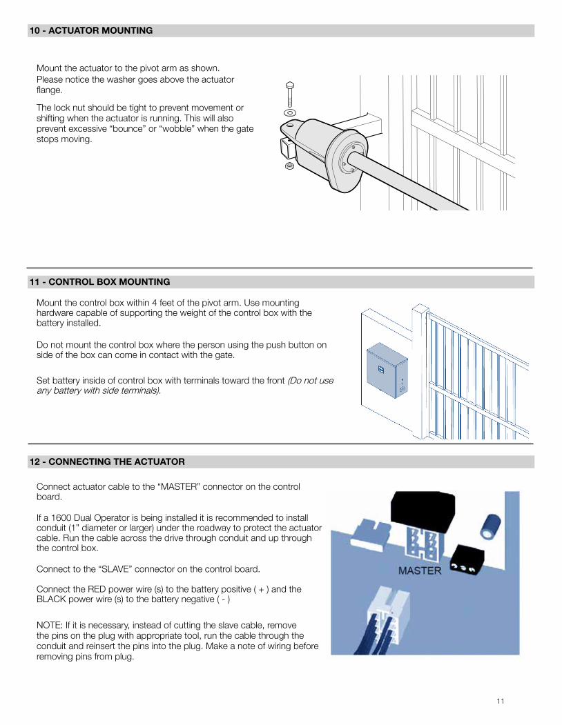
Mount the actuator to the pivot arm as shown. Please notice the washer goes above the actuator flange.
The lock nut should be tight to prevent movement or shifting when the actuator is running. This will also prevent excessive “bounce” or “wobble” when the gate stops moving.
Mount the control box within 4 feet of the pivot arm. Use mounting hardware capable of supporting the weight of the control box with the battery installed.
Do not mount the control box where the person using the push button on side of the box can come in contact with the gate.
Set battery inside of control box with terminals toward the front (Do not use any battery with side terminals).
Connect actuator cable to the “MASTER” connector on the control board.
If a 1600 Dual Operator is being installed it is recommended to install conduit (1” diameter or larger) under the roadway to protect the actuator cable. Run the cable across the drive through conduit and up through the control box.
Connect to the “SLAVE” connector on the control board.
Connect the RED power wire (s) to the battery positive ( + ) and the BLACK power wire (s) to the battery negative ( - )
NOTE: If it is necessary, instead of cutting the slave cable, remove the pins on the plug with appropriate tool, run the cable through the conduit and reinsert the pins into the plug. Make a note of wiring before removing pins from plug.
12
13 - GATE BRACKET MOUNTING
14 - LIMIT SWITCH ADJUSTMENT
Pull to Open only: Activate push button on the side of the control box and extend the actuator until it stops (leave actuator retracted for PUSH TO OPEN).
WARNING: Do not let extension tube rotate as it extends. Do not insert fingers or tools in the hole at the end of the extension tube.
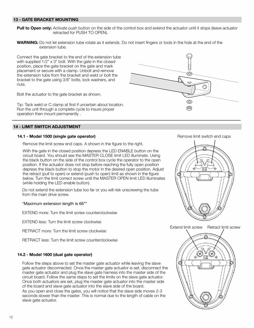
Connect the gate bracket to the end of the extension tube with supplied 1/2” x 3” bolt. With the gate in the closed position, place the gate bracket on the gate and mark placement or secure with a clamp. Unbolt and remove the extension tube from the bracket and weld or bolt the bracket to the gate using 3/8” bolts, lock washers, and nuts.
Bolt the actuator to the gate bracket as shown.
Tip: Tack weld or C clamp at first if uncertain about location. Run the unit through a complete cycle to insure proper operation then mount permanently .
14.1 - Model 1500 (single gate operator)
Remove the limit screw end caps. A shown in the figure to the right.
With the gate in the closed position depress the LED ENABLE button on the circuit board. You should see the MASTER CLOSE limit LED illuminate. Using the black button on the side of the control box cycle the operator to the open position. If the actuator does not stop before reaching the fully open position depress the black button to stop the motor in the desired open position. Adjust the retract (pull to open) or extend (push to open) limit as shown in the figure below. Turn the limit correct screw until the MASTER OPEN limit LED illuminates (while holding the LED enable button).
Do not extend the extension tube too far or you will risk unscrewing the tube from the main drive screw.
*Maximum extension length is 66”*
EXTEND more: Turn the limit screw counterclockwise
EXTEND less: Turn the limit screw clockwise
RETRACT more: Turn the limit screw clockwise
RETRACT less: Turn the limit screw counterclockwise
Remove limit switch end caps
Extend limit screw Retract limit screw
14.2 - Model 1600 (dual gate operator)
Follow the steps above to set the master gate actuator while leaving the slave gate actuator disconnected. Once the master gate actuator is set, disconnect the master gate actuator and plug the slave gate harness into the master side of the circuit board. Follow the same steps to set the limits on the slave gate actuator. Once both actuators are set, plug the master gate actuator into the master side of the board and slave gate actuator into the slave side of the board. As you open and close the gates, you will notice that the slave side moves 2-3 seconds slower than the master. This is normal due to the length of cable on the slave gate actuator.
13
15 - 635/636 CONTROL BOARD CONNECTIONS
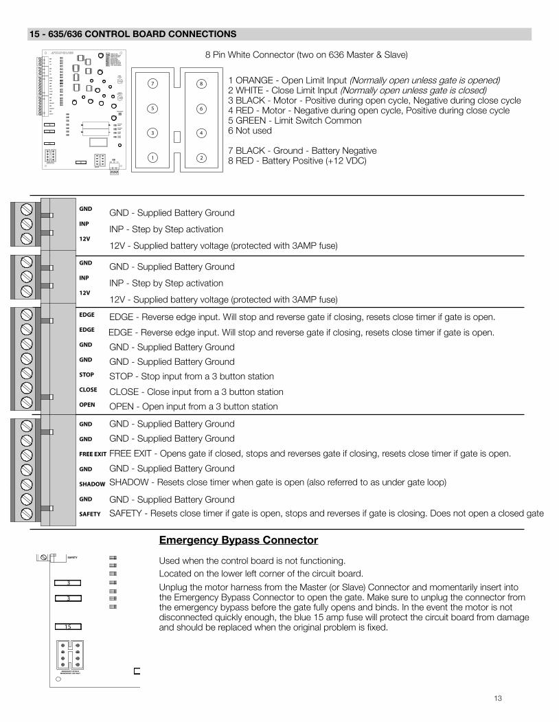
8 Pin White Connector (two on 636 Master & Slave)
1 ORANGE - Open Limit Input (Normally open unless gate is opened) 2 WHITE - Close Limit Input (Normally open unless gate is closed) 3 BLACK - Motor - Positive during open cycle, Negative during close cycle 4 RED - Motor - Negative during open cycle, Positive during close cycle 5 GREEN - Limit Switch Common 6 Not used
7 BLACK - Ground - Battery Negative 8 RED - Battery Positive (+12 VDC)
GND - Supplied Battery Ground
INP - Step by Step activation
12V - Supplied battery voltage (protected with 3AMP fuse)
GND - Supplied Battery Ground
INP - Step by Step activation
12V - Supplied battery voltage (protected with 3AMP fuse)
EDGE - Reverse edge input. Will stop and reverse gate if closing, resets close timer if gate is open.
EDGE - Reverse edge input. Will stop and reverse gate if closing, resets close timer if gate is open.
GND - Supplied Battery Ground
GND - Supplied Battery Ground
STOP - Stop input from a 3 button station
CLOSE - Close input from a 3 button station
OPEN - Open input from a 3 button station
GND - Supplied Battery Ground
GND - Supplied Battery Ground
FREE EXIT - Opens gate if closed, stops and reverses gate if closing, resets close timer if gate is open.
GND - Supplied Battery Ground
SHADOW - Resets close timer when gate is open (also referred to as under gate loop)
GND - Supplied Battery Ground
SAFETY - Resets close timer if gate is open, stops and reverses if gate is closing. Does not open a closed gate
Emergency Bypass Connector
Used when the control board is not functioning.Located on the lower left corner of the circuit board.
Unplug the motor harness from the Master (or Slave) Connector and momentarily insert into the Emergency Bypass Connector to open the gate. Make sure to unplug the connector from the emergency bypass before the gate fully opens and binds. In the event the motor is not disconnected quickly enough, the blue 15 amp fuse will protect the circuit board from damage and should be replaced when the original problem is fixed.
TIMER TO CLOSECURRENT SENSE DELAYTIMER TO CLOSE OPT.SLAVE DISABLEMASTER DISABLEMAX RUN TIMER OPT.MAX RUN TIMER VALUETIMER TO CLOSE VALUE“STOP” CIRCUIT ENABLE
TIMERTO CLOSE
CURRENTSENSITIVITY
GND INP 12V
MASTEROPEN
MASTERCLOSE
SLAVEOPEN
SLAVECLOSE
GND
INP
12V
GND
INP
12V
EDGE
EDGE
GND
GND
STOP
CLOSE
OPEN
GND
GND
FREE EXIT
GND
SHADOW
GND
SAFETY
LED ENABLE
MASTER
EMERGENCY BYPASSMOMENTARY USE ONLY
3
3
3
15
7
5
3
1
8
6
4
2
TIMER TO CLOSECURRENT SENSE DELAYTIMER TO CLOSE OPT.SLAVE DISABLEMASTER DISABLEMAX RUN TIMER OPT.MAX RUN TIMER VALUETIMER TO CLOSE VALUE“STOP” CIRCUIT ENABLE
TIMERTO CLOSE
CURRENTSENSITIVITY
GND INP 12V
MASTEROPEN
MASTERCLOSE
SLAVEOPEN
SLAVECLOSE
GND
INP
12V
GND
INP
12V
EDGE
EDGE
GND
GND
STOP
CLOSE
OPEN
GND
GND
FREE EXIT
GND
SHADOW
GND
SAFETY
LED ENABLE
MASTER
EMERGENCY BYPASSMOMENTARY USE ONLY
3
3
3
15
GND
INP
12V
GND
INP
12V
EDGE
EDGE
GND
GND
STOP
CLOSE
OPEN
GND
GND
FREE EXIT
GND
SHADOW
GND
SAFETY
14
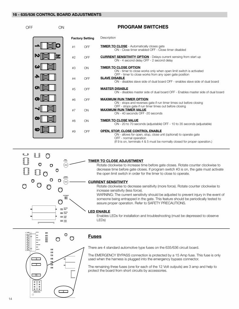
16 - 635/636 CONTROL BOARD ADJUSTMENTS
PROGRAM SWITCHES
Description
TIMER TO CLOSE - Automatically closes gate ON - Close timer enabled OFF - Close timer disabled
CURRENT SENSITIVITY OPTION - Delays current sensing from start up ON - 4 second delay OFF - 2 second delay
TIMER TO CLOSE OPTIONON - timer to close works only when open limit switch is activated OFF - timer to close works from any open gate position
SLAVE DISABLEON - disables slave side of dual board OFF - enables slave side of dual board
MASTER DISABLEON - disables master side of dual board OFF - Enables master side of dual board
MAXIMUM RUN TIMER OPTIONON - stops and reverses gate if run timer times out before closing OFF - stops gate if run timer times out before closing
MAXIMUM RUN TIMER VALUEON - 40 seconds OFF -20 seconds
TIMER TO CLOSE VALUEON - 20 to 70 seconds (adjustable) OFF - 10 to 35 seconds (adjustable)
OPEN, STOP, CLOSE CONTROL ENABLEON - allows for open, stop, close unit (optional) to operate gate OFF - normal operation (If 9 is on, terminals 4 & 5 must be normally closed for proper operation.)
OFF ON
Factory Setting
#1 OFF
#2 OFF
#3 ON
#4 OFF
#5 OFF
#6 OFF
#7 ON
#8 ON
#9 OFF
Fuses
There are 4 standard automotive type fuses on the 635/636 circuit board.
The EMERGENCY BYPASS connection is protected by a 15 Amp fuse. This fuse is only used when the harness is plugged into the emergency bypass connector.
The remaining three fuses (one for each of the 12 Volt outputs) are 3 amp and help to protect the board from short circuits by accessories.
TIMER TO CLOSE ADJUSTMENT Rotate clockwise to increase time before gate closes. Rotate counter clockwise to
decrease time before gate closes. If program switch #3 is on, the gate must activate the open limit switch in order for the timer to close to operate.
CURRENT SENSITIVITY Rotate clockwise to decrease sensitivity (more force). Rotate counter clockwise to
increase sensitivity (less force). WARNING: The current sensitivity should be adjusted to prevent injury in the event of
someone being entrapped in the gate. This feature should be periodically tested to assure proper operation. Refer to SAFETY PRECAUTIONS.
LED ENABLE Enables LEDs for installation and troubleshooting (must be depressed to observe
LEDs)
TIMER TO CLOSECURRENT SENSE DELAYTIMER TO CLOSE OPT.SLAVE DISABLEMASTER DISABLEMAX RUN TIMER OPT.MAX RUN TIMER VALUETIMER TO CLOSE VALUE“STOP” CIRCUIT ENABLE
TIMERTO CLOSE
CURRENTSENSITIVITY
GND INP 12V
MASTEROPEN
MASTERCLOSE
SLAVEOPEN
SLAVECLOSE
GND
INP
12V
GND
INP
12V
EDGE
EDGE
GND
GND
STOP
CLOSE
OPEN
GND
GND
FREE EXIT
GND
SHADOW
GND
SAFETY
LED ENABLE
MASTER
EMERGENCY BYPASSMOMENTARY USE ONLY
3
3
3
15
15
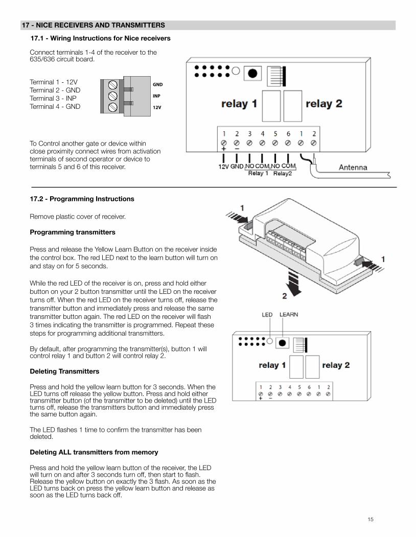
17 - NICE RECEIVERS AND TRANSMITTERS
17.2 - Programming Instructions
Remove plastic cover of receiver.
Programming transmitters
Press and release the Yellow Learn Button on the receiver inside the control box. The red LED next to the learn button will turn on and stay on for 5 seconds.
While the red LED of the receiver is on, press and hold either button on your 2 button transmitter until the LED on the receiver turns off. When the red LED on the receiver turns off, release the transmitter button and immediately press and release the same transmitter button again. The red LED on the receiver will flash 3 times indicating the transmitter is programmed. Repeat these steps for programming additional transmitters.
By default, after programming the transmitter(s), button 1 will control relay 1 and button 2 will control relay 2.
Deleting Transmitters
Press and hold the yellow learn button for 3 seconds. When the LED turns off release the yellow button. Press and hold either transmitter button (of the transmitter to be deleted) until the LED turns off, release the transmitters button and immediately press the same button again.
The LED flashes 1 time to confirm the transmitter has been deleted.
Deleting ALL transmitters from memory
Press and hold the yellow learn button of the receiver, the LED will turn on and after 3 seconds turn off, then start to flash. Release the yellow button on exactly the 3 flash. As soon as the LED turns back on press the yellow learn button and release as soon as the LED turns back off.
17.1 - Wiring Instructions for Nice receivers
Connect terminals 1-4 of the receiver to the 635/636 circuit board.
Terminal 1 - 12V Terminal 2 - GND Terminal 3 - INP Terminal 4 - GND
To Control another gate or device within close proximity connect wires from activation terminals of second operator or device to terminals 5 and 6 of this receiver.
16
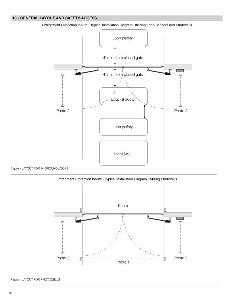
18 - GENERAL LAYOUT AND SAFETY ACCESS
Entrapment Protection Inputs - Typical Installation Diagram Utilizing Loop Sensors and Photocells
Figure - LAYOUT FOR IN-GROUND LOOPS
Entrapment Protection Inputs - Typical Installation Diagram Utilizing Photocells
Figure - LAYOUT FOR PHOTOCELLS
Loop (safety)
Loop (shadow)
Loop (safety)
Loop (exit)
Photo 2 Photo 2
4’ min. from closed gate
4’ min. from closed gate
Photo 2 Photo 2
Photo
Photo 1

17
20 - MAINTENANCE SCHEDULE
Table 2
1 Year 6 Months
Check the battery for any leakage or loose connections. Batteries should be replaced when depleted
If equipped - Check emergency vehicle access device for proper operation
Inspect for damage
Check that the gate reverses on contact with an object in both the opening and closing cycles
Check vehicular reverse and shadow loops for proper operation
Check and tighten bolts and nuts
Battery ● ●
Fire Dept ● ●
Gate ●
Reverse System ●●
Loop(s) ●
Mounting Hardware ●
21 - TROUBLESHOOTING
Table 3
SYMPTOM(S) POSSIBLE SOLUTION
With charging device disconnected - check battery voltage (should be between 12-14VDC)
If voltage measures OK, check the terminal block connection to the board
Check terminal block wiring for loose or broken wires
Check the gate and actuator for binding or problems
If no binding is present adjust current sensitivity to increase strength
Check the input LEDs. Any open inputs ON will hold the gate open and indicates a possible problem with an accessory Check the secondary safety devices. Any activated safety devices will hold the gate open and indicates a problem with the safety device
Check the limit LEDs. Open limit LED should be lit when gate is fully open
Check the program switches. Switch #1 should be turned ON
Check accessory inputs and clear or reset as necessary
Operator will not run / Power On / do anything
Gate opens a short distance, then stops and reverses
Gate opens but will not close
Timer to close will not close gate
Gate opens by itself
●
18
1 1
2 2
AA
BB
CO
MPA
NY:
NIC
E APO
LLO
NAM
E: C
ON
TR
OL
BO
X G
ENER
AL
OVER
VIE
W
18.22
18.1
8
8.32
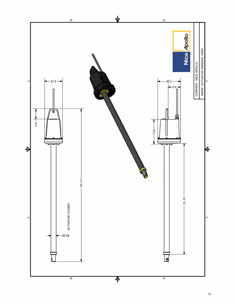
19
1 1
2 2
AA
BB
CO
MPAN
Y:
NIC
E A
PO
LLO
NAM
E:
ACTU
ATO
R G
EN
ER
AL
VIE
W
43.1
7
ACTU
ATO
R C
LOSED
7.385.74
31.4
1
4.0
3.0
Ø1.66
7.0
1
20
PART
S LI
STD
ESCR
IPTI
ON
PART
NU
MBE
RQ
TYIT
EMCO
NTR
OL
BOX
CABI
NET
1003
1990
11
CON
TRO
L BO
X LI
D10
0162
151
2CO
NTR
OL
BOX
TAB
1002
0915
13
KEYS
WIT
CH, S
ING
LE P
OLE
1115
14
SWIT
CH, P
USH
BU
TTO
N, C
NTR
L BO
X11
191
563
5 CI
RCU
IT B
OAR
D63
5 1
6
1 1
2 2
AA
BB
TITL
E:
Com
pany
:
2
34
5
1
Not
e:Co
ntro
l Box
Cab
inet
Cont
rol B
ox L
idCo
ntro
l Box
Tab
Keys
witc
hSw
itch
Push
But
ton
Also
sol
d as
1 u
nit
part
#11
111B
NIC
E AP
OLL
OCO
NTR
OL
BOX
WIT
H 6
35 B
OAR
D
6
21
PART
S LI
STD
ESCR
IPTI
ON
PART
NU
MBE
RQ
TYIT
EMCO
NTR
OL
BOX
CABI
NET
1003
1990
11
CON
TRO
L BO
X LI
D10
0162
151
2CO
NTR
OL
BOX
TAB
1002
0915
13
KEYS
WIT
CH, S
ING
LE P
OLE
1115
14
SWIT
CH, P
USH
BU
TTO
N, C
NTR
L BO
X11
191
563
6 CO
NTR
OL
BOAR
D63
61
6
1 1
2 2
AA
BB
TITL
E:
Com
pany
:
2
3
4
5
1
Not
e:Co
ntro
l Box
Cab
inet
Cont
rol B
ox L
idCo
ntro
l Box
Tab
Keys
witc
hSw
itch
Push
But
ton
Also
sol
d as
1 u
nit
part
#11
111B
NIC
E AP
OLL
OCO
NTR
OL
BOX
WIT
H 6
36 B
OAR
D
6
22
PAR
TS L
IST
DES
CRIP
TIO
NPA
RT N
UM
BER
QTY
ITEM
GEA
R H
OU
SIN
GA2
011
11
EXTE
NSI
ON
TU
BEA2
027
12
SPU
R G
EAR
A201
71
3
LIM
IT S
CREW
A201
91
4
LIM
IT T
OW
ER B
USH
ING
A200
91
5
MAI
N S
CREW
A201
81
6
SEAL
HO
USI
NG
-AL
UM
INIU
M-
A206
41
7
BEAR
ING
SA2
087
18
COVE
R T
UBE
A209
11
9
AC G
EAR
NU
TA2
006
110
SEAL
A202
51
11
1 1
2 2
AA
BB
7
3
4
5
6
2
1 8
Com
pany
: N
ICE
APO
LLO
Nam
e: A
CTU
ATO
R FR
ON
T H
OU
SIN
G
11
9
10
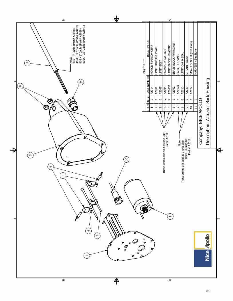
23
PAR
TS L
IST
DES
CRIP
TIO
NPA
RT
NU
MBE
RQ
TYIT
EMM
OTO
R &
PIN
ION
GEA
RA2
014
11
LIM
IT T
OW
ER &
PLA
TEA2
001
12
LIM
IT B
OLT
A200
52
3
PRO
XIM
ITY
SWIT
CHA2
004
24
LIM
IT B
LOCK
- P
LAST
ICA2
003P
25
BRAS
S BL
OCK
W/M
AGN
ETA2
002
16
BACK
, HO
USI
NG
A201
2K1
7
LIM
IT C
AP &
SEA
LA2
010
28
STR
AIN
REL
IEF
A202
91
9
SMAR
T SE
NSO
R (8
16 O
nly)
A207
21
10
HAR
NES
S -
See
Not
e1
11
1 1
2 2
AA
BB
Com
pany
: N
ICE
APO
LLO
Des
crip
tion:
Act
uato
r Ba
ck H
ousi
ng
7
8
11
9
1
10
2
Not
e:Th
ese
Item
s ar
e so
ld a
s 1
unit
also
: Ba
ck H
ousi
ng K
itPa
rt #
A20
12
4
5
6
Not
e:41
6 -
8' C
able
(Pa
rt#
A20
28)
416X
- 3
8' C
able
(Pa
rt#
A20
37)
816
- 8'
Cab
le (
Part
# A
2058
)81
6X -
38'
Cab
le (
Part
# A
2041
)
3
Thes
e It
ems
also
sol
d as
one
uni
t Pa
rt#
A20
38

24
Nice Group USA Limited Warranty – 2 (TWO) YEARS
Nice Group USA (“Manufacturer”) warrants this product shall be free from defects in materials and workmanship for a period of 2 years from the manufacture date. These warranties are in lieu of all other warranties expressed or implied and shall be considered void if the product is damaged due to, but not limited to, improper installation, improper use, terrorism or acts of God. The proper operation of this product is dependent on your compliance with the instructions regarding installation, operation, maintenance, and testing. Failure to comply strictly with those instructions will void this limited warranty in its entirety.
If, during the 2 year time period from the date of manufacture, this product appears to contain a defect covered by this limited warranty, call the manufacturer service center at 1-800-226-0178 before uninstalling and/or dismantling this product. The technical assistance department at the manufacturer will discuss the problems you are experiencing in order to confirm the product defect. You will provide the information from the dated proof of purchase receipt to confirm the warranty period or the technician will confirm your extended warranty period through your registration information on file. The technician will give you the shipping information you need to return your product. Your product must be returned to the manufacturer service center in a prepaid and insured manner. Should your product be covered under the warranty policy, your product will be repaired, replaced with a factory rebuilt product or replaced with a new product (at the manufacturer’s discretion) at no cost to you and sent back to you via standard ground freight.
THIS WARRANTY AND THE OBLIGATIONS AND LIABILITIES OF MANUFACTURER ARE EXCLUSIVE AND IN LIEU OF ALL OTHER WARRANTIES, EXPRESS OR IMPLIED, INCLUDING ANY IMPLIED WARRANTY OF MERCHANTABILITY OR FITNESS FOR A PARTICULAR PURPOSE. Under no circumstances shall the manufacturer be liable for consequential, incidental or special damages of any kind whatsoever. The manufacturer’s liability for a breach of warranty, breach of contract, negligence or strict liability cannot exceed the cost of the warrantied product. No person is authorized to assume for the manufacturer any other liability in connection with the sale of this product.
24 - WARRANTY
25
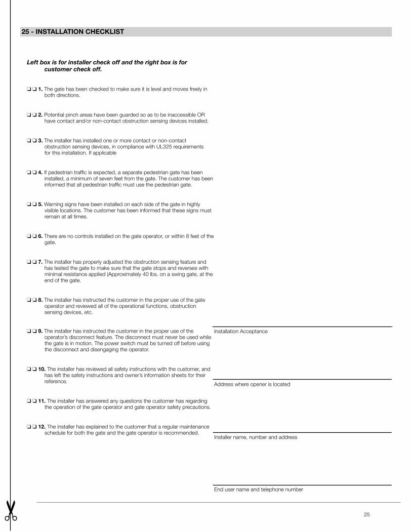
25 - INSTALLATION CHECKLIST
Left box is for installer check off and the right box is for customer check off.
❑ ❑ 1. The gate has been checked to make sure it is level and moves freely in both directions.
❑ ❑ 2. Potential pinch areas have been guarded so as to be inaccessible OR have contact and/or non-contact obstruction sensing devices installed.
❑ ❑ 3. The installer has installed one or more contact or non-contact obstruction sensing devices, in compliance with UL325 requirements for this installation. If applicable
❑ ❑ 4. If pedestrian traffic is expected, a separate pedestrian gate has been installed, a minimum of seven feet from the gate. The customer has been informed that all pedestrian traffic must use the pedestrian gate.
❑ ❑ 5. Warning signs have been installed on each side of the gate in highly visible locations. The customer has been informed that these signs must remain at all times.
❑ ❑ 6. There are no controls installed on the gate operator, or within 8 feet of the gate.
❑ ❑ 7. The installer has properly adjusted the obstruction sensing feature and has tested the gate to make sure that the gate stops and reverses with minimal resistance applied (Approximately 40 lbs. on a swing gate, at the end of the gate.
❑ ❑ 8. The installer has instructed the customer in the proper use of the gate operator and reviewed all of the operational functions, obstruction sensing devices, etc.
❑ ❑ 9. The installer has instructed the customer in the proper use of the operator’s disconnect feature. The disconnect must never be used while the gate is in motion. The power switch must be turned off before using the disconnect and disengaging the operator.
❑ ❑ 10. The installer has reviewed all safety instructions with the customer, and has left the safety instructions and owner’s information sheets for their reference.
❑ ❑ 11. The installer has answered any questions the customer has regarding the operation of the gate operator and gate operator safety precautions.
❑ ❑ 12. The installer has explained to the customer that a regular maintenance schedule for both the gate and the gate operator is recommended.
Installation Acceptance
Address where opener is located
Installer name, number and address
End user name and telephone number

Contact us Nice Group USA Inc. 12625 Wetmore Road Suite 218 San Antonio, TX 78247 Ph. +1.210.545.2900 Fax +1.210.545.2915
www.niceapollo.com www.facebook.com/NiceApollo


![Vol 39 - [Swing, Swing, Swing].pdf](https://static.fdocuments.net/doc/165x107/55cf8f6f550346703b9c5141/vol-39-swing-swing-swingpdf.jpg)