
APD2007_FinalReport_05
78
1 Analytical Product Design Final Report Title: Redesign of Drinking Water Fountain Member of group APD07-05: Mobeen Shaukat Rafael Ramos Adrien Yee Yi Ren Instructor: Panos Y. Papalambros Team consultant: Erin MacDonald
-
Upload
bruno-pergher -
Category
Documents
-
view
2 -
download
0
Transcript of APD2007_FinalReport_05
1
Analytical Product Design
Final Report
Title: Redesign of Drinking Water Fountain
Member of group APD07-05: Mobeen Shaukat Rafael Ramos Adrien Yee Yi Ren
Instructor: Panos Y. Papalambros
Team consultant:
Erin MacDonald

2
Contents
1. Introduction ..................................................................................................................... 4 1.1 Problem statement ..................................................................................................... 5
1.2 Preliminary market research ..................................................................................... 5 1.3 Laws and Regulations ............................................................................................... 6 2. Previous Designs ............................................................................................................. 8
Current Patents .............................................................................................................. 10 3. Design Objectives ......................................................................................................... 11
4. Concept Generation ...................................................................................................... 12 4.1 Brainstorming ......................................................................................................... 12
4.2 Selection of concepts .............................................................................................. 12 4.2.1 Attributes.......................................................................................................... 12 4.2.2 Rejected concepts............................................................................................. 12 4.2.3 Concepts chosen for further consideration ...................................................... 13
4.3 Early sketches and prototypes ................................................................................. 13 4.3.1 Concept #1: Adjustable nozzle ........................................................................ 13
4.3.2 Concept #2: Shaped basin ................................................................................ 14 4.3.3 Concept #3: Leveled nozzle ............................................................................. 14 4.3.4 Concept #4: High pressure stream ................................................................... 15
4.4 Selection criteria and method.................................................................................. 16 4.5 Selected Product Concept ....................................................................................... 16
4.6 Product features ...................................................................................................... 17 5. Quantification of Design Concept ................................................................................ 20
6. The Engineering Design ............................................................................................... 22 6.1 Design Attributes .................................................................................................... 22 Ergonomic Consideration ......................................................................................... 22
Hygienic Consideration ............................................................................................ 22 Strength Consideration.............................................................................................. 23
6.2 Design with Mathematical Methods ....................................................................... 23 Ergonomic Optimization Model ............................................................................... 23 Basin Spine Design ................................................................................................... 26 Drain Radius Design ................................................................................................. 29 Strength Consideration.............................................................................................. 30
6.3 Design with Experimental Methods ........................................................................ 31 Beta prototype ........................................................................................................... 31
Basin Boundary and Depth Design ........................................................................... 32 6.4 CAD Model .............................................................. Error! Bookmark not defined. 6.5 Conclusion .............................................................................................................. 34
7. Choice Based Conjoint Analysis .................................................................................. 35 7.1 Logit model ............................................................................................................. 35
7.2 Composition of the utility and CBC results ............................................................ 35 8. The Microeconomic Model........................................................................................... 37
8.1 Market Size ............................................................................................................. 37

3
8.2 Cost Estimates ......................................................................................................... 38
Costs independent from design variables ............................................................... 38 Costs dependent on design variables ...................................................................... 38 8.3 Market Share Estimates .......................................................................................... 39
8.3.1 Assumption ..................................................................................................... 39 8.3.2 Utilities from competitors and fE ................................................................... 39 8.4 Profit Model ............................................................................................................ 41
9. Future Work .................................................................................................................. 42 Modeling methods ........................................................................................................ 42
Concepts realization ...................................................................................................... 42 10. Design in the Designed World .................................................................................... 43
Appendix 1 – Business Plan ............................................................................................. 44 Appendix 2- Previous Designs Schematics ...................................................................... 51
Appendix 3 - Relevant Patents .......................................................................................... 53 Appendix 4 - ADA-compliance of the Drinking Fountain ............................................... 54
Appendix 5 - Brainstorming ideas .................................................................................... 55 Appendix 6 - QFD Chart................................................................................................... 57 Appendix 7 - Product Development Process .................................................................... 58
Appendix 8 - Pugh ............................................................................................................ 59 Appendix 9 - Gantt Chart .................................................................................................. 60
Appendix 10 - Survey 1 .................................................................................................... 61 Summary of Survey 1 Results................................................................... 63 Appendix 11 - Survey 2 .................................................................................................... 64
Appendix 12 - Finite element analysis (FEA) used in progress report ............................. 67
Fountain body ........................................................................................... 67 Basin shape ............................................................................................... 68
Appendix 13 - Product architecture .................................................................................. 69
Appendix 14 – Matlab codes ............................................................................................ 72
Figure 1 Drinking fountain ADA requirements .................................................................. 7
Figure 2 Adjustable nozzle concept .................................................................................. 14
Figure 3 Shaped basin concept ......................................................................................... 14
Figure 4 Leveled nozzle concept ...................................................................................... 15
Figure 5 High pressure stream concept ............................................................................. 16
Figure 6 Detailed CAD of product features and user posture ........................................... 17
Figure 7 Water consumption - Nozzle diameter2 diagram ............................................... 18
Figure 8 Clam shell ........................................................................................................... 19
Figure 9 Expanded view of fE .......................................................................................... 19
Figure 10 Determine users satisfactory by bending angle ................................................ 24
Figure 11 ADA requirements for bottle filling ................................................................. 27
Figure 12 The contact angle α........................................................................................... 27
Figure 13 Design with different nozzle position............................................................... 28
Figure 14 Design with different shooting angle ............................................................... 28

4
Figure 15 Final design characteristics............................................................................... 29
Figure 16 Block diagram of beta prototype ...................................................................... 31
Figure 17 Beta prototype top view.................................................................................... 32
Figure 18 Beta prototype side view .................................................................................. 32
Figure 19 Beta prototype fixture ....................................................................................... 33
Figure 20 Design flow ...................................................................................................... 34
Figure 21 Beta values for bending angles ......................................................................... 36
Figure 22 Beta values for colors ....................................................................................... 36
Figure 23 Beta values for filling times ............................................................................. 36
Figure 24 Beta values for prices ....................................................................................... 36
Figure 25 Microeconomic model ...................................................................................... 37
Figure 26 Market size estimation ...................................................................................... 37
Figure 27 Business Plan: Drinking water fountain shipments .......................................... 44
Figure 28 Business Plan: Breakeven timeline .................................................................. 49
Figure 29 Stress analysis of fountain body thickness = 2.108 .......................................... 67
Figure 30 Stress analysis of fountain body thickness = 3.048 .......................................... 68
Figure 31 Stress analysis of initial basin design ............................................................... 69
Figure 32 Stress Analysis of modified basin shape .......................................................... 69
Table 1 Design objectives for Ergo Water Fountain ...................................................... 11
Table 2 Design Variables ................................................................................................ 20
Table 3 Nomenclature for Ergo Design .......................................................................... 24
Table 4 Optimization Results for Nozzle Height ............................................................ 25
Table 5 Nomenclature for Ergo Water Fountain ............................................................ 26
Table 6 Strength Analysis Var./Para. .............................................................................. 30
Table 7 Design Methods for Experiments ...................................................................... 33
Table 8 Beta values ......................................................................................................... 35
Table 9 Components cost ................................................................................................ 38
Table 10 Utility for fE....................................................................................................... 40
Table 11 Utilities for competitors ..................................................................................... 40
Table 12 Final optimization results................................................................................... 41
Table 13 Business Plan: Advantages of fE ....................................................................... 47
Table 14 Business Plan: Cost estimation .......................................................................... 48
Table 15 Business Plan: Net present value ....................................................................... 48
Table 16 FEA Results of fountain body ........................................................................... 67
Table 17 FEA Results of basin shape ............................................................................... 68

5
1. Introduction
1.1 Problem statement
Drinking water fountain design is over one hundred year old. Observation of drinking
fountain use at the University campus indicated that there is room for improving the
design of these fountains. More specifically, ergonomics, aesthetics, and hygiene of
drinking fountains can be improved through a better design. Along the same lines, more
features can be added to drinking water fountains that will enhance the end user
experience. This project presents the design effort to improve the ergonomics, aesthetics,
and hygiene of drinking water fountains.
1.2 Preliminary market research
A customer survey was distributed to University of Michigan students based on the
problem statement to identify their concerns of using drinking water fountains in the
campus. The survey can be found in Appendix 5 of this report. The survey had 45
respondents, mainly university students.
At the beginning of the survey, a question determines if the respondent is qualified to
take survey by asking if they use the drinking water fountain. This question qualified 42
respondents who use drinking fountain. In the following question, it is found that 81% of
these respondents use the drinking water fountain at least once a day. The responses to
both questions show that the drinking fountain is one of the sources of drinking water for
the majority of students when they are in the university campus and hence any issues
associated with the drinking fountain will most likely have a significant impact.
A quick search on the internet will tell one that one of the main issues of using the
drinking fountain is the quality of the water. Based on initial findings of our team, some
drinking fountains are not frequently examined for their water quality. In some cases, the
level of contaminants (e.g. arsenic, lead, etc) in the drinking fountains goes above the
safety standards undetected until a complaint is made. Among the respondents who are
concerned with the hygiene of using the drinking fountain, 31% of the respondents are
either moderately or extremely concerned. Based on their feedback, they are doubtful of
the water quality as well as the cleanliness of the drinking fountain itself due to heavy
public usage. Besides, 50% of the fountain users are bothered by the splash of water from
the fountain.
In general, not many know how drinking water is processed in the existing drinking
fountains. This is strongly supported by the survey which shown that 88% of the users
cannot identify the type of filtering process in a drinking fountain. This may be one of
factors that deter some respondents from drinking as much as they would from a trusted

6
water source such as bottled water. Provision of information such as periodical water
quality, type of filter and its life span may reassure the user and therefore further establish
drinking fountain as main source of drinking water in university buildings.
The ergonomics of using water fountain deals with the posture while operating the
fountain and properties of the water consumed (e.g. temperature, flavor, etc). Only 26%
of the respondents felt uncomfortable with the posture and 14% did not like the taste of
the water. Survey analysis on the limited number of respondents could not identify
relationship between user height and discomfort level. The respondents who felt
uncomfortable with the posture chose back (73%), neck (36%), and hair (27%) as the
causes of discomfort. In order to attain optimum ergonomic posture for fountain users,
the team needs to find the optimum fountain height based on the survey‟s average height
of around 172 cm.
Other than drinking directly from the fountain, the users also use it to fill up bottles. Most
the drinking fountains in the university do not provide separate water dispensing
mechanism for filling bottle. From the survey, it is found that 71% of the respondents are
using fountain for this purpose in which 43% of them had difficulty to do so. Through
observing fountain users, they typically spend an average of 30 seconds to fill up a 500-
800ml water bottle. A more efficient water dispensing mechanism may be to cut filling
time to and possibly reduce wastage of water.
While the design of a drinking fountain is mainly to provide drinking water, the
aesthetics aspect of it, especially in a building, can be used not only to give an
extraordinary drinking experience but even provide a good atmosphere for learning
experience in the university. Although only 24% of the survey respondents thought that
the drinking fountain was not aesthetically pleasing, the drinking fountain may still be
added with cost-effective artistic features to become a highly desirable designer piece.
1.3 Laws and Regulations
Water
Based on our research, the water dispensed through the drinking fountain is regulated for
its quality and its temperature. The Safe Drinking Water Act (SDWA) regulates the
quality and safety of drinking water to protect public health. It regulates 90 contaminants
to their allowable levels as set by Environmental Protection Agency (EPA) and
specifically controls lead contamination through several provisions. EPA recommends
drinking fountain to be taken out of service if lead level reaches 20 ppb. In simplifying
our product design, our team assumes that the quality of the water supply to the drinking
fountain meets the standards and no contaminants are added to the water within the
system. On the other hand, refrigerated drinking water fountain is required to deliver
water temperature between 40˚F to 50˚F by the American National Standard Institute.
Our drinking water fountain will incorporate simple temperature control mechanism to
conform to this requirement.

7
Physical Dimensions
The American with Disabilities Act (ADA) placed several constraints on the physical
dimensions of an ADA-compliant drinking fountain to ensure accessibility for disabled
people. Dimensions relevant to our drinking fountain are the distance between the wall to
the front edge of the unit (430-485 mm), max height of nozzle from the ground (915 mm)
and min height of lower edge of the unit to the ground (685 mm). In addition, the nozzle
must be within 75 mm from the front edge of the unit and shall direct the water flow in a
trajectory that is parallel or nearly parallel to the front of the unit. The nozzle shall
provide water stream of at least 4 in (100 mm) high to accommodate insertion of a cup or
glass under the flow of water. As for the unit controls, it shall be front mounted or side
mounted near the front edge.1
Figure 1 Drinking fountain ADA requirements
1 http://www.access-board.gov/adaag/html/adaag.htm#4.15

8
2. Previous Designs
There are many different types of drinking water fountains currently available. Among
the biggest manufacturers there are Haws, Elkay, Halsey Taylor. Here is some examples
representative of each of the major categories of water fountains. Detailed engineering
schematics are in Appendix 1.
Category1: Indoors
Wall mounted
Haws 1001FR Wall Mounted Drinking Fountains
Model 1001 is a barrier free, stainless steel drinking
fountain with round sculpted bowl. Bubbler, waste
strainer and push button are polished chrome plated
brass. Model includes vandal resistant bottom plate,
special mounting plate and 1-1/4" O.D. waste arm. It
is manufactured in 18 gauges, Type 304, No. 4 satin
finish stainless steel for easy maintenance and
provides the perfect finishing touch for any project.
Recessed
Haws 2405 Recessed Wall Mounted Drinking Fountains.
Model 2405 is a barrier free, fully recessed, stainless steel drinking
fountain in a 18 gauge, type 304, no. 4 satin finish. It is designed to be
installed above a wheel chair access area. It features front mounted push
button valve and vandal resistant, polished chrome plated brass bubbler
head and waste strainer. The mounting consists of furnished hanging
brackets and screws. 1-1/4" O.D. waste arm. Provision for trap (not
included) must be made in or behind wall. Model 2405 meets all current
Federal Regulations for the disabled, including those in the Americans
with Disabilities Act. Haws manufactures drinking fountains, electric
water coolers and electric drinking fountains to be lead free by all
known definitions including ANSI/NSF Standard 61, Section 9, California Proposition 65
and the Federal Safe Drinking Water Act.
1 Pictures and data collected from www. Doctordrinkingfountain.com

9
Pedestal mounted
Haws 3377 Pedestal Mounted Drinking Fountains
Model 3377 is ideal for pedestrian and wheelchair access.
This pedestal drinking fountain may be installed indoors or
outdoors. It features sculpted bowl, front push button,
polished chrome plated brass bubbler head and waste
strainer, hose bib access hole, no. 4 satin finish stainless
steel receptor and bracket, heavy gauge galvanized steel
pedestal with green powder coated finish with top access
plate and vandal resistant screws, push button valve with
automatic stream regulation, vandal resistant bottom plate
on fountain and 1/2" NPT screwdriver stop. Fountain
contains a 12" square integral mounting base with four bolt holes. Anchor bolts are
furnished. Model 3377 meets all current Federal Regulations for the disabled including
those in the Americans with Disabilities Act.
Category: Outdoors
Pedestal mounted
Haws 3060 Pedestal Mounted Drinking Fountains.
Model 3060 is a durable and vandal resistant circular, vibracast-reinforced
concrete pedestal drinking fountain with exposed aggregate finish that is a
perfect complement to all outdoor environments. Vandal resistant features
include bubbler hooded by an extension of the precast pedestal to deter bubbler
damage. It is manufactured with the highest quality cement, select aggregates
and sand. Model 3060 includes push button valve with automatic stream
regulation, concrete guard for polished chrome plated brass bubbler head,
stainless steel access plates with vandal resistant screws and 1/2" NPT
screwdriver stop. Standard color is Portland Gray cement with exposed
aggregate finish. Pedestal is reinforced with 3/16" galvanized wire. The mounting
consists of three furnished integral mounting brackets plus anchor bolts. Matching stone
plugs conceal mountings.

10
Current Patents
Some patents for existing drinking water fountains include:
Patent No.: US D545, 109 S – “FOUNTAIN”
Patent No.: US D547, 104 S – “DRINKING FOUNTAIN”
Patent No.: Des 343,330 – “DRINKING FOUNTAIN”
See Appendix 3 – Current Patents for patent details.
These patents provided us with a preliminary understanding of how certain materials (like
aluminum) are used often to help standardize elements like the basin, in order to achieve
a minimum level of hygiene. This also facilitates cleaning with standard cleaning
products.

11
3. Design Objectives
The overall objective of current design activity is to enhance the experience of water
fountain user by improving the form and function of water fountain. After observing
users, analyzing survey data, and reviewing the current products available, design
objectives given in Table 1 were selected for the project.
Table 1 Design objectives for Ergo Water Fountain
Design Objective Quantitative Measurement
Ease of use Comfortable posture – back angle
Effort to activate the fountain
Height of fountain
Ease of filling bottle Effort required to fill the bottle
Time required to fill the bottle
Improved Hygiene Surface area of basin
Drain rate of water
Information availability Information display for ads, news etc.
Water quality display
Improved visual appeal Color appeal on scale of 1 – 5
Shape appeal on scale of 1-5
Material appeal on scale of 1- 5
Competitive pricing Price equal to current water fountain
Overall user satisfaction User satisfaction on scale of 1 -7
These objectives fall into three categories: function, form, and business. The function of
the current water fountain will be enhanced by improving the ergonomics of the fountain
and at the same time by providing extra features that are currently not available, like
information display.
Initial survey indicated that there is room for improving aesthetics of water fountain.
Aesthetics is very subjective and difficult to measure. However, subjective rating will be
used to compare the improved design versus the current design. Shape, color, and
material will be varied to improve the aesthetics of the fountain. The goal of the project
will be to make water fountain a sculpture piece that at the same time serves the purpose
of quenching thirst.
Since the user group and buyer for this product are different, it is difficult to develop a
business objective. Users selected for the study are students whereas buyer is the
construction firm or the University. Nevertheless, the goal of the project will be to
provide added functionality and visual appeal at a comparable price of a current water
fountain.
These objectives were used to construct the QFD that is given in Appendix 6. Also
several concepts were evaluated using these objectives. This concept selection process is
explained in the next section.

12
4. Concept Generation
In this chapter the solution concepts are developed and addressed in the effort of finding
the most promising solution for further analysis. This is done by using brainstorming to
develop the concepts, followed by a careful categorization of concepts and a systematic
decision making process. Finally, the design requirements that can be quantified for
engineering analysis are chosen.
4.1 Brainstorming
With existing observation, survey analysis and design requirements, the team came up
with 24 concepts by brainstorming, each of which aimed at some of the requirements.
These ideas were further filtered through group discussion and voting, ended up with 4
favorite choices. Pugh chart was then applied with the guidance of weighted design
requirements, and a final decision was made. Other concepts were also reviewed as
substitutes. The list in Appendix 4 shows the results of the brainstorming.
4.2 Selection of concepts
An initial selection of the most reasonable concepts was made starting from the original
brainstorming. Some of the original concepts where considered too extravagant or likely
to be prohibitively expensive. We also noted that some concepts have similar function,
and are more like attributes that can be added to other ones (listed in 4.2.1).
4.2.1 Attributes
Numbers 1-7 are identified as attributes, which fall in the following categories:
*Trigger improvement: 1, 2, 4 and 7
*Hygienic devices: 3
*Bottle filling facility: 5 and 6
4.2.2 Rejected concepts
Number 13 and 16 are already on the market so these ideas are not relevant in the further
development of a new product.
Number 14 is obviously not cost-effective and unfriendly to users. Number 15 is
applicable but not appealing to manufacturers as well as maintenance, and it‟s also
expensive to build.

13
Ideal ergonomic targets will be met by applying number 17 and 20; however, these
concepts obviously neglect hygiene concerns, which are in fact, one of the most
important considerations in our design.
Number 19, 21 and 22 are scrapped simply because we have similar ideas of these.
Number 18, where users with different height can easily approach the fountain without
adjusting their posture, is also discarded. An obvious reason for discarding this idea is the
possible unpleasant water splash. Other obstacles with this concept include its drainage
system and its coordination with surroundings.
Number 24 is space demanding and is somewhat redundant in its function. Number 12 is
also canceled because it involves too much material which our team need to avoid.
Moreover, we have no idea how to convince our manufacturers to produce an instant
product with little profit.
Number 23 is scrapped as well because there might be too much work to accomplish, and
since none of our team members have EE background, this idea is not practical.
4.2.3 Concepts chosen for further consideration
Concepts 8, 9, 10 and 11 are considered as possible solutions. They are all capable of
fulfilling the design objectives in some way. Furthermore, the team considered the
manufacturability of these four options and it is concluded that these concepts are both
feasible to realize and cost-efficient to meet demands. A more comprehensive analysis of
the concepts is thus given below.
4.3 Early sketches and prototypes
Brief hand sketches and CAD models were built to visually understand and evaluate
concepts. This is done to facilitate team discussion over whether and how these concepts
meet the requirements and to explore possible questions in the concepts.
4.3.1 Concept #1: Adjustable nozzle
The concept shown in Figure 2 consists of an adjustable nozzle, both in-plane position
and its height, which allows the user to drink with left and right neck rotation
(conventionally, people use drinking fountain by rotating their necks to the right). Further
development in this direction will involve design decisions like: the number of nozzles
needed, the rotation angle of the nozzle, a appropriate rotation force and the physical
dimension of the basin. A disadvantage of this concept is that bottle filling facility is not
included.

14
Figure 2 Adjustable nozzle concept
4.3.2 Concept #2: Shaped basin
This solution shown in Figure 3 is developed to eliminate remained water in basin. Also,
the curved basin shape was supposed to help avoid water splash on the use. By adapting
this concept, several things needed to discuss further: 1. What contour of the basin we
need to meet our desirable result, that is, both eliminate remained water and reduce water
splash; 2. What nozzle position and stream pressure we need to cooperate with the basin
contour to meet our goals; 3. What materials to apply to the basin so that from
manufacturer perspective, this design is cost effective to produce; 4. Again, the basic
physical dimensions will need to be discussed.
Figure 3 Shaped basin concept
4.3.3 Concept #3: Leveled nozzle
This solution is a straight answer to our design objectives. Both leveled nozzles and
bottle filler are included. The bottle filler suppose to acquire range or force sensor so
button is omitted. By installing leveled nozzles, our goal is to reduce bending motion of

15
users, thus in turn increase their satisfaction of drinking posture. One significant problem
with this concept is that higher nozzle increase the possibility of water splash, which
could only be eliminated by either increasing the basin radius or reducing the stream
pressure. However, neither amendment has positive effect on user satisfaction. So, the
main objective of this concept realization is to optimize its function by appropriate design
of the elements mentioned above.
Figure 4 Leveled nozzle concept
4.3.4 Concept #4: High pressure stream
A water station is an extension of the previous concept with higher stream pressure.
Water shoots from left side to right side so people can approach water directly. This idea
is somewhat fancy and a major problem is whether people can afford this high water
pressure. Further research of water property will be needed if we go this way.

16
Figure 5 High pressure stream concept
4.4 Selection criteria and method
The four concepts have been illustrated and one primary concept is going to be chosen.
Pugh chart is introduced to rank these concepts. Specific criteria are imported from QFD
shell and weights are given based on team discussion. For each criterion, concepts are
evaluated from -3 to +3 by members‟ knowledge and experience. As can be seen in the
chart, the result yields one positive score (Concept #2) and three negative ones. The gaps
among scores are significant. This is because weighting coefficients for design objectives
are relatively high. We all consider the result valid and Concept #2 is finally chosen.
4.5 Selected Product Concept

17
Figure 6 Detailed CAD of product features and user posture
Figure 6 shows a compilation of views of detailed CAD of product features including the
view of a potential user.
4.6 Product features
Hygiene
The hygiene of aspect of the drinking fountain is improved with an innovative basin
design. It is designed to reduce water splash to the user by making the contact point
between the water droplets and basin surface 37 degrees more parallel. The water splash
is significantly reduced compared to a flat basin design. As presence of water promotes
growth of germs, the shape of the basin surface is also designed to closely resembles a
brachistochrone curve i.e. curve of fastest descent to minimize water containment on the
basin. This shape will considerably reduce the water left on the basin than a flatter
design.
Water consumption
Info display
Automatic sensing
Bottle filler
Nozzle
Splash
reducer

18
In determining the diameter of the nozzle, results from an experiment done by K.
Coetzee, and C. Bennett in 19781 are analyzed. This experiment studies the effect of
nozzle diameter on drinking time, water utilization, water consumption and power used
per user within a range of 3mm to 9mm. A 6mm nozzle diameter is chosen for highest
water consumption of 60 cm3 per person while compromising 15% lower water
utilization and 10% higher power used per user.
Figure 7 Water consumption - Nozzle diameter2 diagram
Accessibility
Using the drinking fountain is effortless with automatic sensing controls placed at easily
accessible location. With this control mechanism, the user can use the drinking fountain
without having to touch it, hence eliminating hygienic concern. For filling bottles, a
simple yet effective feature, with a small basin and automated filler, is added to make the
process quick and easy. The drinking fountain will also comply with the ADA
requirements for disabled users (Appendix - ADA Requirements).
Information display
With the information display screen, various types of information will be shown to the
users. If the information displayed is attractive to the user, it should encourage more users
to drink from the fountain. Real-time information such as weather and time, Mbus
arrivals, news and events, etc can be easily acquired and shown. In addition, the “health”
status of the drinking fountain will also be available to the user by simply stating the filter
change due date.
Emotional Design
1 K. Coetzee, and C. Bennett , The efficiency of a drinking fountain, Applied Ergonomics 1978, 9.2, 97-100

19
The drinking fountain incorporates emotional design to inflict a sense of hygiene and
purity in the mind of the users with shiny finishing on the stainless steel fountain body
and basin. The clam shell shaped basin will also improve the ambience in a building and
contribute to people feeling positive about the surroundings.
Figure 8 Clam shell
Modularity
By integrating modularity the product architecture, the drinking fountain can be easily
customized to address specific user needs. The bottle filler and information display
screen can be optionally packaged with the basic drinking fountain. Besides, the basin
shape can be tailor-made to different shapes to match its environment. For instance, it can
be shaped like an opened book to be placed in a library.
Figure 9 Expanded view of fE

20
5. Quantification of Design Concept
This part is initialized in our proposal report and during the design process we gradually
refined our variables, parameters, constraints and objectives in the model. The final
quantification of our design concept is presented here before the detailed analysis as a
preview of our optimization model. More detailed descriptions and connections can be
found in the Chapter 6 and 7.
Variables, Parameters1, Constraints and Objectives:
Table 2 Design Variables
Variable/Parameter Description
*Basin
Shape: Basin spine characteristic length a, angle φ:
These values define the Brachistochrone
spine;
Parameter
Width: w: Basin widths are essential variables for
splash design. We conducted experiments
using our beta prototype to decide these
widths.
Variable
Thickness: t: It refers to the thickness of the basin Variable
*Nozzle
Position: hn : It refers to the height of the nozzle from
the basin bottom; Variable
Shooting angle: β: It refers to the shooting angle of the stream; Variable
Trajectory: u, v are local coordinates of the stream
trajectory;
Parameter
*Drain
Radius: Rd : It controls the drain rate and is
determined by the flow rate;
Parameter
*Installation
Fountain height: h : Different fountain height will have
different ergonomic score according to our
survey analysis and ergo model;
Variable
*Economic
Price: P : Price influents the market share as well as
engineering attributes, thus is also involved; Variable
%Market: Pr : Market share is determined using logit
model where user utilities are inputs;
Parameter
Revenue: R : The total income throughout 5 years‟
business plan;
Parameter
Total cost: C: Based on the fixed investment, unit cost
and estimated market share of our product.
Parameter
1 Here “Parameter” means all the intermediate values calculated during the design process.

21
Constraint Related to: Description
*Mechanical Const.
ADA requirements: Fountain height h (in our
design, this constraint is
relaxed, see economic model
for details);
Supporting pipe length L;
Nozzle position from the far
end of the supporting pipe Dn;
See Appendix for
detailed requirements.
Basin bending stress: max (shape_basin a, φ,
width_basin w, test load) y
(mat)
Here y is chosen as
the stress limitation of
stainless steel.
*Ergonomic Const.
Distance between user
head and basin surface:
Derg(Stream trajectory u, v,
shape_basin a, φ) 50mm;
From common
knowledge, people will
feel uncomfortable if
the basin surface is too
near. This value is set
as 50mm in our design.
User back bending
angle: (fountain height h, Stream
trajectory max{v}, user stature)
erg;
erg is an ergonomic
recommended interval
of back bending angle,
we assume erg =[0,
90].
*Hygienic Con.
Drain rate: rate_drain(drain radius Rd,
shape_basin a, φ, stream
trajectory u, v) Stream rate;
higher than stream rate
to achieve drain
effectiveness.
*Bottle Filling Con.
Height of the filler hf hbottle The average bottle
height hbottle
Radius of the filler
basin
Rf Rbottle The average bottle
height Rbottle
Objective Description
Sergo+Ssplash: This objective is used in the engineering design
optimization phase where Sergo and Ssplash are scores for
ergonomic and splash performance of our design (see
Chapter 6 for more information). This objective is further
introduced in to the logit model where we estimate our
market share in the economic optimization.
Profit P: Profit is our ultimate objective of the economic
optimization based on all the analysis, surveys and
assumptions we made. (see Chapter 7 for more
information)

22
6. The Engineering Design
All pieces of engineering design discussions are presented here: An optimization method
is first used to find the best height for the fountain; then both a mathematical model and a
beta prototype is built to search for the best basin shape in terms of splash reduction and
drain rate improvement; finally, we exam the drain efficiency by determining the drain
radius. During this process, assumptions are made based on both online database and
common sense.
6.1 Design Attributes
Ergonomic Consideration
The performance of a drinking water fountain is highly related to its interaction with
users. From our survey analysis as well as own experience, current designs lack credits to
prove itself as an ergonomically pleasing interface. Unfortunately, as we found out in our
project, designing a fountain in a more ergonomic way somehow conflicts with ADA
requirement, which is an essential attribute in design and market though not mandatory.
Current designs treat this dilemma in two ways. One, adjust the basin to a lower position
to meet ADA requirement of fountain height. The cost of this compromise will be high if
the fountain is installed at some place with rare ADA access like gym. The other way is
to make modulus products, usually two fountain sets with different height to both meet
the needs of ADA requirements and achieve better ergo performance. The team also
discussed the possibility of making the fountain vertically adjustable, and we agreed that
there will be much more trivial things to take care about if we go this way, and moreover,
since adjustable basin involves the new problem of increasing user time consumption, we
don‟t think it is wise to bring ourselves this problem.
Thus, in our design, we mainly focused on improving the fountain ergo performance by
determine the best basin height for both male and female users. An optimization model
on this issue is later built and calculation carried out. In the model, we defined a scoring
mechanism based on user bending angle, and the target is written as a weighted sum
value of total score.
Hygienic Consideration
This part contains two goals: increasing drain rate and minimizing splash.
Splash
Splash is annoying and it always exits with drinking water fountain. Two ideas correlated
in this issue and will help us to move forward are ‟How to efficiently reduce splash with
a given basin size?‟ and „What is the minimum basin boundary to hold the splash?‟
Intuitively, adding beads at appropriate places in the basin will tackle the first problem
and with a given stream rate and basin depth, it is easy to define a basin by bounding it

23
with maximum splash radius. Since none of the team member is expertise in fluid, we
used experiments to iteratively find the solution for these two problems and the derived
the converged result.
Drain Rate
A major concern about drinking water fountain is its hygiene. Two problems exist:
firstly, lead contamination occurs in public fountain; secondly, the basin surface was
reported to have significant amount of germs. We decided not to include the former one
in our design since it involves piping system. The latter problem is treated as equal to
minimize the droplet remain on the basin surface after use. This design target then helps
us to form the main spine of the basin.
A covered bubbler is also used (like current designs) to prevent lips or flow of water from
mouth to splash on the spout itself.
Strength Consideration
Besides the above, we also build an approximated model to calculate the basin bending
stress by using theoretical analysis and making assumptions to simplify our problem.
This model is further used as a nonlinear constraint in the optimization model.
Please understand that we did not use Catia FEA model in our final optimization model.
However, a separated FEA model can be found in the progress report. Commercial
software will be used to link Catia FEA model with our profit model (See Chapter 8) in
our future work. (See Chapter 10)
6.2 Design with Mathematical Methods
Ergonomic Optimization Model
The basic idea is to use back bending angles as an indicator of user satisfaction. A survey
analysis with the help from Dr. Erin Macdonald helped us to quantify user preference on
the bending angle. The result is shown below:

24
Figure 10 Determine users satisfactory by bending angle
It is arguable whether we need more angles on human body besides back bending angle
to better interpret user experience, however, it is reasonable to identify back bending
angle as the major indicator of user satisfaction.
A detailed list of variables, parameters, constants and objectives is shown below:
Table 3 Nomenclature for Ergo Design
Name Description
H = Stature height of the user, 5% -95% for both male and female Constant
h = Basin height, or more precisely, the nozzle height Variable
hw = Maximum stream height: max{v} Linking variable
U = The distance from mouth to the top Parameter
r = golden ratio (0.62) Constant
θ = User bending angle Parameter
S(θ) = Score for a certain θ Parameter
SE = Total ergonomic score Objective
SM = Score for male user Parameter
SF = Score for female user Parameter
µM = Mean value for male stature height distribution Constant
µF = Mean value for female stature height distribution Constant
бM = Standard deviation for male stature height distribution Constant
бF = Standard deviation for female stature height distribution Constant
PM(H) = Probability density of stature height H for male users Parameter
PF(H) = Probability density of stature height H for female users Parameter

25
With the assumption that people drink water from the highest point of the stream
(max{v}) and the bending point divides upper and lower body with golden ratio, the
bending angle is given by:
θ = acos(hw + h − Hr
H(1 − r))
Based on the regression of the conjoint analysis result, score (utility) of this certain angle
is:
S θ = −0.072θ2 + 0.541θ − 0.232
And the weighted score is:
Si = Pi(H)S(θ)dH Where i = F, M.
And thus the total score is given by:
S = 1
2 Pi(H)S(θ)dH
H i95
H i5i=M,F
Constants and parameters are given values based on database and assumptions:
Data Source
U =200mm Assumption
HF95= 1736mm, HF5= 1521mm Anthropometric Reference Data for
Children and Aults: U.S. Population,
1999-20021
HM95= 1895mm, HF5= 1628mm
µF = 1628mm, µM = 1767mm
бF = 99.68mm, бM = 78.03mm
A MATLAB toolbox is then used to find the optimal solution for this program, and the
results are given below:
Table 4 Optimization Results for Nozzle Height
Optimization Results:
h (the nozzle height) = 133.2 cm
SE (Total ergonomic score) = 0.52
1 Here we use data for U.S. citizens in the range between 20 – 29 years old. By keeping
the same methodology, the program can be easily modified for other user groups.

26
Basin Spine Design
In this part we try to minimize the droplet remained on the basin surface. Although there
are other ways to achieve this goal, e.g. changing the material to increase water
repellence, we focus on the basic physical method to maximize the usage of gravity. The
existing Brachistochrone solution helps us to “find the shape of the curve down which a
bead sliding from rest and accelerated by gravity will slip from one point to another in the
least time”. Although it is arguable since fluid behavior is different from that of solid
bead, however, this method is still applicable because it meets our goal to maximize the
usage of gravity.
The Brachistochrone curve is actually the equations of an inverse cycloid, as shown
below:
x = a(θ − sin(θ))
y = −a(1 − cos(θ))
This equation set assumes zero friction, which is not the fact in our case. We will resort
to the equation set which enables dynamic friction after we decide the basin surface
material.
In the similar fashion as we did in the ergonomic model, a detailed list of variables,
parameters, constants, constraints and objectives is shown below:
Table 5 Nomenclature for Ergo Water Fountain
hn = Nozzle height from drain Variable
ln = Nozzle distance from drain Parameter
v = Stream velocity Parameter
β = Nozzle shooting angle Variable
α = Contact angle between stream and basin surface Objective
a = Character value for basin spine Parameter
φ = π , Character angle for spine at the drain Constant
R = 3.5‟, Radius of the supporting pipe Constant
Derg50mm, Distance between user head and basin surface Constraint
Lb= πa, Basin length limitation Constraint
ADA = The distance for ADA requirement Constraint
Explanation of the nomenclature is given below:
1. From common knowledge, people will feel uncomfortable is the basin surface is too
near when they are drinking. This value is set as 50mm in our design.

27
2. Basin length limitation: From the point of material cost, the idea length will be
exactly long enough to cover the stream trajectory. With the given design function of
basin spine and the assumption of stream rate and angle, visual experiments are
carried out to find the best spine length.
3. ADA requirement on stream trajectory height: This height should be more than 4
inches from the basin to enable bottle insertion.
Figure 11 ADA requirements for bottle filling
4. The lower end of the basin spine should have a descent direction to ensure drain is
effective. For our equation set, this indicates θ ∈ [0, π]. Here we fix θd = π for θ at
the drain.
Figure 12 The contact angle α
5. The nozzle shooting angle β should not be zero, i.e. shooting directly upwards is not
allowed, according to the regulation. Here we set β ∈ 𝜋
6,𝜋
2 .
6. From our design concept, the nozzle is place on a pipe of 3.5 inches. Refer to
Engineering Analysis for details about this pipe.
7. The angle of the stream hitting the basin α (the contact angle) should be minimized to
reduce the splash. We found certain research report to prove our intuitive guess.
A mathematical model is then built in MATLAB to play with and optimize the contact
angle. The results are shown below.

28
Figure 13 Design with different nozzle position
Figure 14 Design with different shooting angle
Conclusions:
1. From our calculations, hn should be at least 60mm high from the bottom to meet the
ADA requirement;
2. With given stream velocity and angle, the minimum α is reached when the nozzle is
placed at the highest possible position.
3. The minimum α is reached at the lower boundary of β.
0 0.05 0.1 0.15 0.2
-0.12
-0.1
-0.08
-0.06
-0.04
-0.02
0
0.02
0.04
Nozzle at 1.5r
Nozzle at 2r
0 0.05 0.1 0.15 0.2
-0.12
-0.1
-0.08
-0.06
-0.04
-0.02
0
0.02
0.04Shooting Angle = 30deg
Shooting Angle = 45deg

29
Figure 15 Final design characteristics
Drain Radius Design
Sufficient drain radius will ensure the whole system performance. Here we calculate the
radius based on the model we‟ve discussed above. Notice that this is only a first order
model where we treat droplets as solid rigid bodies and basin as ideally smooth surface;
while the stream pressure at the nozzle and drain are the same (we cut a hole in the drain
pipe to meet this goal). Thus the drain radius is given by the XXX:
𝑅𝑛2𝑣1 = 𝑅𝑑
2𝑣2
, where Rn is the radius of the nozzle, v1 and v2 are stream velocity at the nozzle and the
drain accordingly.
Notice that the stream lost part of its velocity when contacting the basin surface, and
there is a height gap between the nozzle and the drain. Based on the optimized design, the
relationship between v1 and v2 is then given as:
1
2𝑣12 =
1
2𝑣32 + 𝑔(2𝑎 − 𝒉𝒏)
𝑣1′ = 𝑣3cos(𝜶)
0 0.05 0.1 0.15 0.2 0.25-0.14
-0.12
-0.1
-0.08
-0.06
-0.04
-0.02
0
0.02
0.04
0.06
x/m
y/m
Nozzle
Shooting angle = 30deg
Stream velocity = 1.6m/s
Nozzle position from drain:
hn = 3.5 inches
ln = 0
Contact angle = 37.0deg
Basin spine design:
Total length: 200.9mm
Total Height: 127.9mm

30
1
2𝑣1′2 + 2𝑔𝑎 =
1
2𝑣22
Given values of v1(1.6m/s), a (64mm), hn (89mm) and 𝜶 (37deg) according to the design
results, the minimum value for Rd is calculated as 2.7mm.
However, we find out later in the test run that this radius is far from enough the produce
sufficient drain rate. The problem could be that the pressure at the drain is practically
higher than that of the nozzle, thus lead to the decrease of v2 and higher Rd.
Strength Consideration
The simplified strength analysis model is given below:
The dimensions of the basin cross-section at the bottom, the inertial moment, and the
main axis are determined by the results from “Experimental Methods” section (See
section 6.3); the length of the basin is determined by “Basin Spine Design”; the applied
load is set as 80kg and the safety coefficient as 1.5. All values are listed below:
Table 6 Strength Analysis Var./Para.
Var./Para. Description Value Units
Parameters
M Applied load 80 kg
mu Safety coefficient 1.5 /
g Gravity constant 9.8 m/s2
L Basin length Determined by Basin Spine
Design
mm
c Maximum distance from the
principal axis
Determined by Experiments mm
I Moment of inertia of the cross-
section
Determined by Experiments mm4
Variable
t Basin thickness / mm

31
The stress constraint is then given by:
𝜎 =𝑀𝑐
𝐼=
𝑚𝑔𝜇𝐿𝑐
𝐼(𝑡)≤ 𝜎𝑦
6.3 Design with Experimental Methods
We studied several reports on the topic of droplets‟ behaviors. However, formulas given
in those papers are not coherent with our experimental results. The problem might be the
difference between the Reynolds number/Weber number of fountain stream and that of
single droplets used in those papers. Thus, we conducted our design with experiments
based on our beta prototype.
Beta prototype
Due to the nature of the project, it was determined that a system that could help emulate
water flow into the basin shape would be of great value. This prototype aims at
demonstrating the design concept can be realized into an actual product. It is intended as
a first step to demonstrate that the architecture proposed can be built with real materials
at an appropriate cost, and that it is likely to meet most of the design requirements,
including functionality and user appeal.
Ideally it is portable, so it can be used for demonstration purposes as well.
Figure 16 Block diagram of beta prototype
As can be seen in Figure 16, there is a submersible water pump contained in a reservoir
that feeds through a “wall” into the basin. The water is collected and returned into the
container creating a closed loop.

32
Figure 17 Beta prototype top view
The basin shape of this prototype is built with copper rods as its skeleton and a
waterproof curtain as its surface. The side view of the skeleton is formed by previous
discussion on spine. The curtain is clipped to the skeleton at five fixed points. This
fixture helps us to easily reshape the basin by changing its length, width and depth.
Figure 18 Beta prototype side view
Basin Boundary and Depth Design
The idea here is to determine the basin boundary with the maximum splash radius along
the spine, and thus minimize the basin surface area. Besides, it is intuitively true that we

33
can reduce splash by using deeper basin, however, this method also increase the basin
surface area. Thus, our goal is to make the best compromise between splash and surface
area via experiments.
In detail, we separate the clips into two sets: the upper three (A, B and C as shown in the
figure below) and the lower two. By loosening or tightening these two sets of clips, we
can examine the different performance of splash and drain rate. The results are shown
below:
Figure 19 Beta prototype fixture
Table 7 Design Methods for Experiments
Method Observation
Case Tighten Loosen Splash/Drain Surface area
1 A B C D E Upper side splash 0
2 D E A B C Upper side splash
Water remains in the basin
+
3 All / Returning water goes out of
the basin
-
4 / All Good performance ++
Conclusions:
1. Both in case 1 and 2, upper side splash occurs because the stream almost hits the
upper boundary of the basin, which is true in the previous math model. So the basin
spine should be extended to hold this part of splash.
A
B C
D E

34
2. In case 2, water remains in the basin because the basin surface is almost flat thus the
drain is not efficient. So clip D E should be loosened appropriately to enhance drain
rate.
3. In case 3, water goes out of the basin because depth is not enough and thus enables
water to flow in other paths. From the point, we decide to add beads to create a
definite drain path. Also, when placed at proper positions, beads also help to reduce
splash.
4. In case 4, we obtain a fairly good performance by loosening all the clips, however,
this also increases the total surface and in turn the material cost.
Although there is no quantitative method available, iterative tries can help us to find a
qualified performance for both splash and drain rate. Both basin boundaries and depth are
decided by the experiment and used in the CAD model.
6.4 Conclusion
As a conclusion, the design flow chart is shown below. This is further used in the
microeconomic model where the whole picture is completed.
Figure 20 Design flow

35
7. Choice Based Conjoint Analysis
7.1 Logit model
Briefly, a logit model with CBC (choice-based conjoint) analysis serves to estimate the
probability of people choosing one product among the others, and further estimate the
market share of this product. This probability is given as:
𝑃𝑖𝑗 =𝑒𝑣𝑖𝑗
𝑒𝑣𝑖𝑗 ′𝑗 ′
, where i represents the ith
consumer, j represents the jth
product and vij is the utility value
of product j according to consumer i (here we assume that consumer preferences are
identical, so i can be omitted). In our model, the detailed form of %market is given
below:
%𝑚𝑎𝑟𝑘𝑒𝑡𝑓𝐸 =𝑒𝑣𝑓𝐸
𝑒𝑣𝑐𝑜𝑚𝑝𝑒𝑡𝑖𝑡𝑜𝑟𝑠 + 𝑒𝑣𝑁𝑜𝑛𝑒 + 𝑒𝑣𝑓𝐸
, where 𝑒𝑣𝑐𝑜𝑚𝑝𝑒𝑡𝑖𝑡𝑜𝑟𝑠 are utility values from other drinking fountain manufacturers 𝑒𝑣𝑁𝑜𝑛𝑒
is the utility value of choosing not to buy any product given.
7.2 Composition of the utility and CBC results
The utility values can be further decomposed into beta values which indicate people‟s
preferences on different design attributes. The beta values used in this model is listed
below:
Table 8 Beta values
Beta Description
Beta_color User preference on the fountain color
Beta_filler User preference on bottle filler efficiency
Beta_ergo The same as SE in Chapter 6
Beta_splash An alternative expression of contacting
angle α, it is defined as:
(-200tan(α)/pi+50)/50
Beta_price User preference on the price
The values of these betas are obtained by conducting a CBC survey. The survey results
with regression curves are shown below:

36
Figure 21 Beta values for bending angles
Figure 22 Beta values for colors
Figure 23 Beta values for filling times
Figure 24 Beta values for prices

37
8. The Microeconomic Model
Economic analysis for fE consists of estimating the annual US market size of drinking
water fountain, estimating fixed and variable costs for producing water fountain,
estimating market share via logit model and then maximizing profits using optimization.
The complete model is show below while methods used in brackets. Details are discussed
in the following.
Figure 25 Microeconomic model
8.1 Market Size
The market size is given by an authenticate business report1. Here we use the number
from year 2007 as the total market size of drinking water fountain. And we assume that
the premium market our product will aim at is roughly 15% of the total market.
Figure 26 Market size estimation
1 SBI Market Profile: Plumbing Fixtures and Fittings – a market intelligence report,
Find/SVP published products, NY, 1998 (Note: 2007 estimate only)
4230041600457004230044400504005200057000
64000
1992 1993 1994 1995 1996 1997 1998 2003 2007
US Drinking Fountain Shipments

38
8.2 Cost Estimates
Since the product is similar to current products in the market, cost estimates were
obtained by comparing the prices of competitive products. Also, prices of various
replacement parts were obtained that helped to calculate the variable cost of the product.
One thing needs to mention is that the basin price is based on its volume, thus the unit
cost is not a constant. The following table shows the variable costs of components.
Costs independent from design variables
Table 9 Components cost
Variable costs
Component Price
Bubbler 20
Trigger 18
Bottle filler 120
Chiller 440
Supporting 225
LCD screen 80
Basin **
Total 903+
Manufacturing costs
Labor 100
Packaging 25
Shipping 50
Total 175
Total Cost/Unit 1078+
Fixed Costs
Casting Mold 300000*
Assembly Eq 100000
Rent 25000
Salary 250000
Overhead 50000
Total 725000
* We use cast here because the basin shape we created is hard to stamp.
* *The basin price is based on its volume.
Costs dependent on design variables
The basin price is based on its volume and hence linked to basin spine, width and
thickness. An analytical model is built as follows:

39
𝑉𝑜𝑙𝑢𝑚𝑒 =𝒘𝟏 + 𝒘𝟐
2𝐿𝑠𝑝𝑖𝑛𝑒 𝒕
, where w1 and w2 are determined by experiments, t is the basin thickness and 𝐿𝑠𝑝𝑖𝑛𝑒 is
the total length of the spine curve, which is given by the following calculation:
𝐿𝑠𝑝𝑖𝑛𝑒 = 𝑑𝑥2 + 𝑑𝑦2𝜋
0
= 1 + (𝑑𝑦
𝑑𝑥)2
𝜋
0
𝑑𝑥
= 𝑎 (1 − 𝑐𝑜𝑠𝜃)2 + 𝑠𝑖𝑛2𝜃𝜋
0
𝑑𝜃 = 4𝑎
The unit cost for the basin is approximately $5/kg, and the density of the material is set at
7.8e-6kg/mm3. Thus the price for one basin is:
𝐶𝑏𝑎𝑠𝑖𝑛 =𝒘𝟏 + 𝒘𝟐
24𝑎𝒕 ∙ (7.8 ∙ 10−6
kg
mm3) ∙ $5/kg
8.3 Market Share Estimates
8.3.1 Assumption
Predicting market share is always challenging but still essential. In this part we introduce
the Logit model and CBC analysis results (from Chapter 7) to address this problem.
However, some critical assumptions should be highlighted at the first place:
1. The preference of drinking water fountains is coherent throughout consumers and
users. This might be the most arguable assumption we made. However, this
assumption helps us to simply the problem.
2. There are only a few competitors in the market and the products families of these
competitors are both limited in number and stable in design attribute.
3. Design attributes will not change, i.e. people only consider about certain attributes
we analyzed and will not turn to other ones.
8.3.2 Utilities from competitors and fE
Based on the conjoint analysis results in Chapter 7, we calculated utilities from our
product (𝒗𝒇𝑬) and our competitors‟. (𝒗𝒄𝒐𝒎𝒑𝒆𝒕𝒊𝒕𝒐𝒓𝒔)
*𝒗𝒇𝑬:
To address to the ADA requirement on fountain height, we resort to two installation
fixtures: one fountain installed at ADA height (80cm), or bi-leveled fountains with both
ADA height and optimized height. The utilities of both fixtures are listed below:

40
Table 10 Utility for fE
fE fixture 1 Exterior
color
Bottle
filling time
Bending
angle
(Ergo)
Contacting
angle
(Splash)
Price Utility
𝐵𝑒𝑡𝑎
Cooler N/A Chapter 6 Chapter 6 Variable
Beta_color Beta_filler Beta_ergo Beta_splash Beta_price
0.34 0.53 0.52 0.04 / /
fE fixture 2 Exterior
color
Bottle
filling time
Bending
angle
(Ergo)
Contacting
angle
(Splash)
Price Utility
𝐵𝑒𝑡𝑎
Cooler N/A Chapter 6 Chapter 6 Variable
Beta_color Beta_filler Beta_ergo Beta_splash Beta_price
0.34 0.53 0.52 0.04 / /
*𝒗𝒄𝒐𝒎𝒑𝒆𝒕𝒊𝒕𝒐𝒓𝒔:
Two premium market competitors‟ utilities are estimated by determining their beta
values. Both of these are from ELKAY Manufacturing Co., Competitor 1 has bi-leveled
fountains which is similar to our selling strategy; Competitor 2 bears some critical
characteristics that are identical to our design (recessed cooler, redesigned basin). Also,
we assume the ADA requirement is complied with in all cases. The resulting utilities are
shown below:
Table 11 Utilities for competitors
Competitor 1 Exterior
color
Bottle
filling time
Bending
angle
(Ergo)
Contacting
angle
(Splash)
Price Utility
𝐵𝑒𝑡𝑎
Natural N/A According
to ADA
requirement
Beta value
estimated
directly
$1962
Beta_color Beta_filler Beta_ergo Beta_splash Beta_price
-0.08 -0.57 -0.57 (h =
100cm)
-0.3 0.65 -0.87
Competitor 2 Exterior
color
Bottle
filling time
Bending
angle
(Ergo)
Contacting
angle
(Splash)
Price Utility
𝐵𝑒𝑡𝑎
Natural N/A According
to ADA
requirement
Beta value
estimated
directly
$1800
Beta_color Beta_filler Beta_ergo Beta_splash Beta_price
-0.08 -0.57 -1.87 (h =
80cm)
-0.3 0.97 -1.85

41
*𝒗𝑵𝒐𝒏𝒆:
𝑣𝑁𝑜𝑛𝑒 is given by CBC result as -0.74;
As a conclusion, the market share is estimated through the method discussed above.
However, as a “first order” analysis, this estimation may need further revision based on
the following issues: 1. Real consumers (facility managers) may not have the same
preference as survey takers; 2. Competitors may also have new designs with higher
utilities.
8.4 Profit Model
Based on the engineering analysis (Chapter 6), CBC analysis (Chapter 7) and market
estimates in this chapter, we are now able to optimize the profit by establishing the
microeconomic model. The Matlab Opimization Toolbox is used and the final results are
listed below, also, the complete implementation can be found in the appendix:
Table 12 Final optimization results
Var./Para. Description Maximal Solution Reference/Methods
*Basin
Width: w Variable 150mm at the bottom,
200mm at the top
Chapter 6/
Experiments
Thickness: t Variable 1.41mm (active const.*) Chapter 6/Optimized
*Nozzle
Position: hn Variable 88.9mm (active const.) Chapter 6/Optimized
Shooting angle: β Variable 30deg (active const.) Chapter 6/Optimized
*Installation
Fountain height: h Variable 1332mm Chapter 6/Optimized
*Economic
Price: P1 Variable $2184 Chapter 8/Optimized
P2 $3268 Chapter 8/Optimized
%Market: Pr1 Parameter 29%
Pr2 25%
Revenue: R Parameter $14.0m
Total cost: C Parameter $9.0m
Objective Description Maxima
Profit: P $5.0m

42
9. Future Work
Modeling methods
The current engineering and microeconomic models are analytical ones. Some parts still
need fine-tune to produce more convincing results: Catia will be used both in the stress
analysis and basin volume calculation, and further integrated other parts to get the
accurate value for thickness; the economic model can be revised by taking a close look at
our competitors and using more sophisticated logit model.
Concepts realization
It is a pity that we haven‟t realized all the conceptual ideas we bring out during the
brainstorm session, however, this is almost always the fact in design. Concepts like
connection between info display and fountain usage and sensor trigger are not fully
studied in this design but are interesting ideas to look at in the future.

43
10. Design in the Designed World
Is irrationality predictable? – Reflection on market-driven aesthetic design
This question is inspired by two guest lecturers, namely, Prof. Jan-Henrik Andersen and
Mr. Adam Cooper during the Analytical Product Design course. The question itself might
be too broad to talk about in this little space and with very limited knowledge from the
author. However, by questioning and thinking this way the author is offered great
experience and interesting perspective.
Designers have two phases: irrational minds and sensitivity towards the market. The
former one comes from the nature of their work – to create ideas; and the latter from the
objective of their work – to create profit. Somehow in many cases these two phases
conflict with each other and make the design process a run-and-debug loop. On the other
hand, it is commonly acknowledged that consumers nowadays also carry two phases:
unpredictable pursuit of fashion and nitpicky over quality.
Moreover, there still exists a bigger picture where policies are involved. These forces
always bound designers‟ freedom and at the same time reshape consumer‟s preference.
By stating these facts, it seems like demands are not predictable and designers can only
hit the target with luck. However, daily experience with successful brands tells us that
irrationality is predictable.
As an amateur in design field, the author had sufficient learning opportunities during the
project and is fascinated by the theoretical and practical methods used to control the
design. The result might not be professional, however, this learning process helps the
author to rethink „design‟ in a more sophisticated context where the intuitive aesthetic
pursuit of designers is constrained by profit, market, engineering requirements,
manufacturability, time and others. These constraints and objectives separate design apart
from fine art and applied new values to it. The ideas of „Sustainable design‟ and „Design
for society‟ are among them.
A further reflection as well as communication with insiders inspired even more thoughts.
By linking design attributes (in many cases these are engineering attributes), consumer
preference and policies together, we can push the boundary in the most effective fashion
and this leads to controlling the seemingly irrational market.
-- Ren, Yi

44
Appendix 1 – Business Plan
Business Objective
Our proposed business objective can be stated as follows:
To design, manufacture and market a premium drinking water fountain with enhanced
ergonomics, visual appeal, a modern information display and a bottle filler capability.
The traditional drinking fountain design is 100 years old, and our team believes that there
is much room to improve it, in particular in the following areas:
Ergonomics
Hygiene
Aesthetics
Provide additional features
The background research showed that there is a clear trend in the increase of shipments
for drinking fountains within the United States.
Figure 27 Business Plan: Drinking water fountain shipments1
This creates the natural expectation that there will be a well-defined market for a modern
drinking fountain.
1 Source: SBI Market Profile: Plumbing Fixtures and Fittings – a market intelligence
report, Find/SVP published products, NY, 1998 (Note: 2007 estimate only)
42300 4160045700
42300 4440050400 52000
5700064000
1992 1993 1994 1995 1996 1997 1998 2003 2007
US Drinking Fountain Shipments

45
Users The facilities that would have fE fountains are considered to be “high-end”, that
incorporate the fountain into an already modern and sophisticated environment. There is
a stylish and urban atmosphere that is inviting for people to have small groups of people
interacting in the comfort of a relax environment like a lounge area, or next to a lobby
that expects visitors often and that could be interested in having some water to quench
their thirst. At the same time, they get the opportunity to re-fill their standard water
bottle and while this is happening they get relevant information about the weather, local
news or announcements of events of interest to the user. The user also has the confidence
that this drinking fountain has been properly maintain and that it meets an understandable
standard of hygiene, since the station itself displays information about the quality of the
water, last time filters where replaced, etc.
Product Specifications
The beta prototype for the product is shown in the Figure .
Figure 28 Experimental prototype

46
Figure 29 Working prototype in the Design Expo
The key features of fE fountain are:
1. A supporting pipe that houses water supply, water drain, and trigger mechanism.
2. A basin with splash reduction shape
3. Bottle fill mechanism with sensor
4. Information display
The base pipe serves as the backbone of the product. It holds all the components of the
water fountain. Water supply pipe and water drain pipe runs inside the base pipe. The
drain is also the part of the base pipe and it is hidden from the user. That is one of the
major improvement over the current drinking fountains where drain is usually visible and
it collects water and debris.
Two further enhancements over the current water fountain are bottle filler and
information display. Bottle filler is attached to the base pipe and it is marketed as a
separate module. This means, that if a customer do not want a bottle filler then it can be
deleted from the final product. Bottle fill has an automatic sensing mechanism that senses
the bottle and dispenses water as required. Information display is also provided as a
separate module. Info display can be programmed to display customizable information,
weather, news, etc.
Overall, with all these features fE is a superior product as compared to any existing water
fountains.
Market Analysis Our research reveals that there are less than ten major manufacturers of drinking water
fountains. Some of them include Elkay, Halsey Taylor and Sunroc. Their prices range
from $400 to more than $2500 depending on the finishing, materials used and number of
basins per station.

47
Within the new buildings at the University of Michigan it has been found that the water
fountains installed are the higher end priced ones. We are making the business model
assumption that 15% of the target market is “premium”, meaning facilities or locations
that are new, or that present architectural and interior design elements that give the
visitors of the facility a sense of modern and progressive visual arrangements. With fE
the plan is to capture up to 50% of the total premium market within five years.
A summary of the advantages of fE over Existing Water Fountains is shown in the next
table.
Table 13 Business Plan: Advantages of fE
fE
Existing water fountains
Consumer Improved ergonomics
Less splash
Bottle fill
Information display
High back angle
Splash and stagnant water
Bottle fill only on limited
fountains
No information display
Customer Improved aesthetics
Customization
Revenues from ads
Old design
No/minimal customization
No revenues
Financial Data
Costs, Manufacturing and Pricing
Many things within the plan to reduce the overall cost of fE have to do with a broad
vision of the processes entailed to generate a product of this nature. For instance, due to
the exclusive architecture that characterizes the basin of the fE drinking water fountains it
is proposed that the casting of it be made in-house. Since the architecture of the design is
meant to be modular in the sub-assemblies, this allows for the basin to be constructed as
an independent entity. The remaining components can be commercial off the shelf
purchased from third parties. As far as personnel required it has been calculated that 2
engineers and 3 technicians in the assembly area would satisfy the requirements during
the first few years. For characteristic finishing of the products (for instance painting and
other special materials before shipping) there will be a list of suppliers with which there
would be a previous agreement of their rates and material costs. A summary of the costs
is shown in the next tables.

48
Table 14 Business Plan: Cost estimation
Variable costs
Component Price
Bubbler 20
Trigger 18
Bottle filler 120
Chiller 440
Supporting 225
LCD screen 80
Basin **
Total 903+
Manufacturing costs
Labor 100
Packaging 25
Shipping 50
Total 175
Total Cost/Unit 1078+
Fixed Costs
Casting Mold 300000*
Assembly Eq 100000
Rent 25000
Salary 250000
Overhead 50000
Total 725000
* We use cast here because the basin shape we created is hard to stamp.
* *The basin price is based on its volume.
Table 15 Business Plan: Net present value
Net Present Value
Year 0 1 2 3 4 5
Investment 400000 0 0 0 0 0
Fixed Costs 325000 325000 325000 325000 325000 325000
Unit Sales 0 480 1139.424 2045.341 3289.889 4992
COGS 0 778361.5 1847674.62 3316697 5334840 8094960
Revenue 0 1273246 3022431.72 5425463 8726747 13241760
Net Profit 0 169884.6 849757.1 1783766 3066907 4821800
Tax @ 35% 0 59459.62 297414.985 624318.1 1073418 1687630
Net Profit -725000 110425 552342.115 1159448 1993490 3134170
Net Present Value $3,646,028.23

49
By assuming that we will achieve the estimated market share in 5 years and with an
annual sales increase of 37%, the Net Present Value (NPV) is around $3.6m (See Table
15).
Figure 30 Business Plan: Breakeven timeline
By the second year according to your calculations we would breakeven, suggesting that
the fE business model is strong, complementing a good NPV and with the satisfaction
that a great product has been placed in high end locations within reach of the mainstream
users.
Business Assumptions
1. The preference of drinking water fountains is coherent throughout consumers and
users.
2. There are only a few competitors in the market and the products families of these
competitors are both limited in number and stable in design attribute.
3. Design attributes will not change, i.e. people only consider about certain attributes we
analyzed and will not turn to other ones.
4. We will be able to achieve the estimated market share in 5 years.
5. The premium market size of the drinking water fountain is 15% of the total market.
6. An initial market share of 5% of the premium market can be achieved in the first
year.
7. An annual increase of 37% of our market share can be achieved and maintained for
five year.
8. There will be no significant policies changing and water issues to influence this
market.
($10,000,000.00)
($5,000,000.00)
$0.00
$5,000,000.00
$10,000,000.00
$15,000,000.00
0 1 2 3 4 5
year
Chart Title
Net Profit
COGS
Revenue

50
Existing Patents and Products
United States Design Patent, Clark et. al. Patent No: US D545,109 S, June 26, 2007
United States Design Patent, Hong. Patent No: US D547,104 S, Jul 24, 2007
United States Design Patent, Windenburg et al. Patent No: 343,330, Jan 18, 1994

51
Appendix 2- Previous Designs Schematics

52

53
Appendix 3 - Relevant Patents

54
Appendix 4 - ADA-compliance of the Drinking Fountain
ADA-compliance of the Drinking Fountain

55
Appendix 5 - Brainstorming ideas1
1 Figures are numbered from left to right and top to bottom.

56
1. A pressure control feature added to the handle.
2. Foot triggered drinking fountain.
3. Auto-disinfectant spray added for hygiene concerns.
4. Range motion sensor used to trigger on stream.
5. Efficient bottle filler replacing the existing drinking fountain.
6. A hollow at calculated position in the basin to facilitate efficient bottle filling.
7. Innovative pressure triggered rubber handle.
8. Adjustable (rotatable) drinking fountain to meet demands of people with different
height.
9. Redesigned basin material and shape to improve drain rate.
10. Drinking fountain with three nozzles at different height and separated bottle filler.
11. Water station to meet multiple requirements.
12. Recyclable Paper-made basin to minimize bacteria level of the drinking fountain.
13. A traditional bended nozzle with long neck for bottle filling.
14. Water-fountain-like drinking fountain.
15. Cup-dispenser add-on to alleviate hygiene concerns.
16. Redesigned rotatable nozzle.
17. A snake like adjustable nozzle to achieve better user posture.
18. “Water bar” serving all thirsty creatures.
19. Rotatable and connected handle and nozzle for ergonomic considerations.
20. Direct nozzle with increased stream pressure.
21. Adjustable stream pressure and increased basin depth for better bottle filling
experience.
22. Separated bottle filler.
23. Use inkjet technology to direct water to the bottle or to the user as required
24. A set of three drinking fountains with different height.

57
Appendix 6 - QFD Chart

58
Appendix 7 - Product Development Process

59
Appendix 8 - Pugh

60
Appendix 9 - Gantt Chart

61
Appendix 10 - Survey 1
Drinking Water Fountain Survey
Age: Gender: M F Height:
Occupation: [Student] [Office dweller] or specify other:
Please tick answer in [ ].
1. Do you use a water fountain for drinking water? [ YES ]
[ NO ]
If NO, why not?
2. On average, how many times do you use a water fountain in a day?
[ Seldom ] [ 1 – 5 ] [ 6 – 10 ] [ 11+ ]
3. When do you use the water fountain the most? Please rank:
(1-most often; 4-least likely)
___ after eating ___ coming out of the restroom ___ after gym ___
after work ___ [ other ]
4. Are you concerned about the hygiene of using a water fountain?
[ 1 ] [ 2 ] [ 3 ] [ 4 ] [ 5 ] 1 = Not at all, 2 = Slightly, 3 = Moderately, 4 =Highly, 5 = Extremely
Please specify your concern
______
5. Does the fountain do any of the following to the water:
1. Reverse osmosis
2. Charcoal filtering
3. UV filtering
4. I do not know
6. Is the water:
1. Very Cold
2. Cold
3. Neutral
4. Hot
5. Very Hot
7. Do you like the taste of the water?
[ YES ] [ NO ]

62
8. While using the water fountain, are you concerned about splashing water?
[ YES ] [ NO]
9. While using the water fountain, do you feel comfortable? [ YES ]
[ NO ]
If NO, what makes you uncomfortable?
[ Neck Rotation] [ Back Bending] [ Trigger Position ] [
Long Hair ]
10. Is the design of existing water fountain aesthetically pleasing? Please circle a
number:
Ugly 1 2 3 4 5 Pleasing
11. Do you use the fountain to fill up a water bottle? [ YES
] [ NO ]
If YES, is it easy to fill the bottle? 1 = Very Difficult, 7 = Very Easy
[ 1 ] [ 2 ] [ 3 ] [ 4 ] [ 5 ] [ 6 ] [ 7 ]
12. Do you use fountain for any other purpose than drinking? [ YES ]
[ NO ]
If YES, please specify
13. Would you like to have information displayed next to the fountain? [ YES ]
[ NO ]
If YES, then what sort of information would you like to see? You can select as many as you want.
[ News ] [ Weather ] [ Time ] [ Advertisement ]
Others

63
14. Do you find drinking water fountain noisy?
1. Strongly Agree 2. Agree 3. Neither Agree/Disagree 4. Disagree 5. Strongly
Disagree
15. How satisfied are you with the overall drinking experience from the fountain?
1 = Very Unsatisfied, 7 = Very Satisfied
[ 1 ] [ 2 ] [ 3 ] [ 4 ] [ 5 ] [ 6 ] [ 7 ]
Summary of Survey 1 Results
1. 93% use water fountain 2. 81% use it at least once a day 3. Most often after work 4. 90% concern about the hygiene 5. 88% has no knowledge of filter process in fountain 6. 79% think the water is cold 7. 86% thinks the taste is OK 8. 50% concerned with splash 9. 26% uncomfortable with using existing fountain
a. 36% neck b. 73% back c. 18% trigger position d. 27%hair
10. 24% thinks it’s not aesthetically pleasing 11. 71% fill bottle with water fountain 12. 43% thinks it’s not easy to fill up bottle 13. 10% use for other purpose than drinking/filling bottle 14. 38% wants to see information displayed next to fountain
a. 50% news b. 63% weather c. 63% time d. 19% ads
15. 26% finds it noisy 16. 17% unsatisfied with it

64
Appendix 11 - Survey 2

65

66
*CBC questions continue like this.

67
Appendix 12 - Finite element analysis (FEA) used in progress report
Static stress analysis is carried to determine the specifications of the fountain body and
basin. The cylindrically-shaped fountain body, which acts as the structure of the drinking
fountain, and the basin must withstand worst-scenario load case. Several industrial tube
sizes and various basin designs are analyzed to determine minimum specifications for the
designated load. The load is assumed to be the weight of a 99.99th
percentile American
male of 122.702kg. With safety factor of 2, the Von Mises stress from the FEA must not
exceed half of the yield strength of stainless steel (2.5 x 10⁸ N/m
2). Through several case
studies, the fountain body and basin shape that meet the requirements are found. Variety
In conclusion, the fountain body will be made of a round tube with a nominal size of 3 in.
and wall thickness of 3.1 mm while basin shape B with a slightly thicker cross sectional
profile.
Fountain body
Table 16 FEA Results of fountain body
Nominal
Size
Outer
Diameter
(mm)
Wall
thickness
(mm)
Restraint Basin shape
Von Mises
stress
(N/m2)
3.0in 88.9 2.108 1 side A 1.29
3.0in 88.9 3.048 1 side A 1.03
Figure 31 Stress analysis of fountain body thickness = 2.108

68
Figure 32 Stress analysis of fountain body thickness = 3.048
Basin shape
Table 17 FEA Results of basin shape
Nominal
Size
Outer
Diameter
(mm)
Wall
thickness
(mm)
Restraint Basin shape
Von Mises
stress
(Nm2)
3.0in 88.9 3.048 2 sides A 1.36
3.0in 88.9 3.048 2 sides B 1.14
Restraint
Load

69
Figure 33 Stress analysis of initial basin design
Figure 34 Stress Analysis of modified basin shape
Appendix 13 - Product architecture
By integrating modularity into the product architecture, the drinking fountain can be
easily customized to address specific user needs. The surface finishing and basin shape
can be easily tailored to match its surroundings or convey specific emotion. The bottle
filler and information display screen can be optionally packaged with the basic drinking
fountain. With the modular design, we will be able to produce the parts at costs that do
not differ significantly from the cost of mass producing a single product design.
Restraint
Load
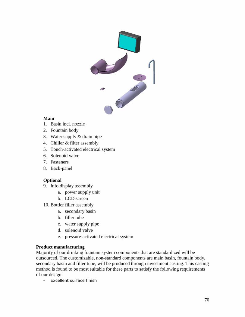
70
Main
1. Basin incl. nozzle
2. Fountain body
3. Water supply & drain pipe
4. Chiller & filter assembly
5. Touch-activated electrical system
6. Solenoid valve
7. Fasteners
8. Back-panel
Optional
9. Info display assembly
a. power supply unit
b. LCD screen
10. Bottler filler assembly
a. secondary basin
b. filler tube
c. water supply pipe
d. solenoid valve
e. pressure-activated electrical system
Product manufacturing
Majority of our drinking fountain system components that are standardized will be
outsourced. The customizable, non-standard components are main basin, fountain body,
secondary basin and filler tube, will be produced through investment casting. This casting
method is found to be most suitable for these parts to satisfy the following requirements
of our design:
- Excellent surface finish

71
- Light weight and thin wall
- Aesthetically pleasing contours
- Structural strength to withstand worst-case load
- Corrosion, abrasion and heat resistant
- Electrical characteristics for touch-activated mechanism
- Interior cavities & passageways for system components and fluid flow
- Small dimensional tolerance to ensure proper fit when joining two parts
- Appearance that can be plated or anodized to meet customized user needs
- Alloys that can be welded or brazed to allow further customization
In addition, investment casting method will also offer several financial and marketing
benefits. The single casting with integrated components (e.g. spout guard) minimizes
secondary processes such as welded fabrication, machining or bolted assembly, saving
time and costs. Additional cost saving is realized by keeping metal usage to a minimum
because castings can be designed and produced to net-shape configuration. Also, the
availability of prototyping and temporary tooling for cast components can be developed
quickly to prove out designs and respond to market demands.
Assembly
The assembly of our drinking fountain components will be primarily carried out on site at
customer‟s location to reduce manufacturing cost and hence, achieve our business goal of
competitive pricing. This is enabled by incorporating design for assembly into the
product with reduced number of part counts by integration as mentioned previously. The
assembly process can be broken down into three main sections:
1) Install and connect chiller and filter assembly systems in the designated wall-
recess
2) Insert and fasten piping and activation systems into basin and assemble to
fountain body
3) Fasten basin and fountain body assembly to back panel and close wall recess
area.

72
Appendix 14 – Matlab codes
The implementation consists three part. Profit.m is the main objective function;
profit_constraint.m is the non-linear constraint function called by fmincon and
Solver_profit.m is the main file where optimization is executed and results listed.
Profit.m
% APD
% Optimization Model
% for Max. Profit
% clear
function P=Profit(X,u,sigma,r1,v,r,sita,L,Q_max,Beta_color...
,Beta_filler,U2,U3,U_none,Cv_constant,Cf)
%------------------------------------------Variables
%-------------------Ergo-----------------------------
% h=85; %Basin height, NEED TO OPTIMIZE
h=X(1);price=X(2:3);
%-----------------------------------------------------
%-------------------Splash----------------------------
% hn=2*r; %Nozzle position from the drain, OPTIMIZED
hn=X(4);
%-----------------------------------------------------
%-------------------Structure-------------------------
t=X(5); %basin thickness, NEED TO OPTIMIZE
%-----------------------------------------------------
%-------------------Economic--------------------------
% price=[1500, 2500];
%-----------------------------------------------------
%------------------------------------------Parameters
%-------------------Splash----------------------------
%-------------------Inputs: v,sita,hn
%-------------------Outputs:S_splash
ln=(r^2-(r-hn)^2)^.5;
ada=(v*cos(sita))^2/2/9.8+hn; %this is hw in the ergo part.
hh=fsolve(@(hh)
v*cos(sita)/9.8*v*sin(sita)+(2*hh/9.8).^0.5*v*sin(sita)-pi*(ada-
hh)/2+ln, [0,0.15]);
hh=min(hh);
a=(ada-hh)/2;
n=1;
for phi=0:pi/100:pi
x(n)=a*(phi-sin(phi));
y(n)=-a*(1-cos(phi));
n=n+1;
end
Tmax=(max(x)-ln)/v/sin(sita);
i=1;
for T=0.00:Tmax/100:Tmax
xx(i)=pi*a-ln-v*sin(sita)*T;
yy(i)=-2*a+v*cos(sita)*T-1/2*9.8*T^2+hn;

73
i=i+1;
end
[Y,ii]=max(yy);
i=find(abs(x-xx(ii))<0.001);
% if yy(ii)-y(i)>4*25.4*0.001&&...
% ((x(length(x))-xx(ii))^2+(y(length(y))-yy(ii))^2)^.5-
100*0.001>=50*0.001
k=(xx(length(xx))-xx(length(xx)-1))/(yy(length(yy))-yy(length(yy)-
1));
S_splash=(-200/pi*k+50)/50;
% end
%-----------------------------------------------------
%-------------------Ergo------------------------------
%-------------------Inputs: u,sigma,h0
%-------------------Outputs: S_ergo
h=real(h);
sita0=37.6/180*pi; % From conjoint analysis
hw=ada; % will be replaced as a variable
hf_low=max(h+hw,132.1);
hm_low=max(h+hw,142.8);
hf=hf_low:(153.6-hf_low)/100:153.6;
hm=hm_low:(169.5-hm_low)/100:169.5;
sita=acos((hw+h-[hf;hm]*r1)./[hf+0.001;hm+0.001]/(1-r1));
S=-0.072*(sita/pi*18).^2+.541*(sita/pi*18)-.232; % coefficients from
conjoint analysis
w=[(153.6-hf_low)/100*normpdf(hf,u(1),sigma(1));...
(169.5-hm_low)/100*normpdf(hm,u(2),sigma(2))];
S_ergo=(S(1,:)*w(1,:)'+S(2,:)*w(2,:)')/2;
S_ergo=real(S_ergo);
%-----------------------------------------------------
%-------------------Structure-------------------------
Stress_basin=0; %Stress calculated at basin bottom
%-----------------------------------------------------
%-------------------Economic--------------------------
% Utilities
% Utilitiy for ergo
Beta_ergo=[-1.4946 S_ergo];
% Utilitiy for splash
Beta_splash=S_splash;
% Utility for price
Beta_price=-0.002*price+4.571;
Current_U=[exp(sum([Beta_ergo(1),Beta_splash,Beta_color,Beta_filler,Bet
a_price(1)])),...
exp(sum([Beta_ergo(2),Beta_splash,Beta_color,Beta_filler,Beta_price(2)]
))];
Total_U=Current_U(1)+Current_U(2)+exp(U2)+exp(U3)+exp(U_none);
Pr=Current_U/Total_U; %market proportion of our design
%Cost related:
%Basin_mat

74
Basin_mat_unit_price=5; %5 dollars per kg
%Basin_Vol
Basin_Vol=4*a*1000*t*(120+300)/2;
Pipe_Vol=r*1000*pi*t*L;
Vol=Basin_Vol+Pipe_Vol;
C_Basin=Vol*7.8/1e6*5;
Cv=C_Basin+Cv_constant;
Cv=[Cv,2*Cv];
%-----------------------------------------------------
%------------------------------------------Objective Function
%-------------------Economic--------------------------
P=-(Q_max*Pr*(price-Cv)'-Cf);
%-----------------------------------------------------
profit_constraint.m
function [C,Cq]=profit_constraint(X,v,r,sita)
%------------------------------------------Constraints
%-------------------Ergo------------------------------
% d_face=50; %the minimum distance between face and basin surface
%-----------------------------------------------------
%-------------------Splash----------------------------
% sita_nozzle_lower=pi/6; %met
%-----------------------------------------------------
%-------------------Structure-------------------------
%Stress
% Stress_Y=2.5e8;
80(mass)*9.8*1.5(coef)*L*20.5(c)/(1.37e4*t)(I)<=2.5e8;
% hn=X(4);
% t=X(5);
ln=(r^2-(r-X(4))^2)^.5;
ada=(v*cos(sita))^2/2/9.8+X(4); %this is hw in the ergo part.
hh=fsolve(@(hh)
v*cos(sita)/9.8*v*sin(sita)+(2*hh/9.8).^0.5*v*sin(sita)-pi*(ada-
hh)/2+ln, [0,0.15]);
hh=min(hh);
a=(ada-hh)/2;
n=1;
for phi=0:pi/100:pi
x(n)=a*(phi-sin(phi));
y(n)=-a*(1-cos(phi));
n=n+1;
end
Tmax=(max(x)-ln)/v/sin(sita);
i=1;
for T=0.00:Tmax/100:Tmax
xx(i)=pi*a-ln-v*sin(sita)*T;

75
yy(i)=-2*a+v*cos(sita)*T-1/2*9.8*T^2+X(4);
i=i+1;
end
[Y,ii]=max(yy);
i=find(abs(x-xx(ii))<0.001);
C=[a*pi/X(5)-.1421;
-yy(ii)+y(i)-4*25.4*0.001;
-((x(length(x))-xx(ii))^2+(y(length(y))-
yy(ii))^2)^.5+100*0.001+50*0.001];
%Dimension
% Basin_width_uppper=6*25.4;
% Pipe_radius_upper=4*25.4;
% Pipe_radius_lower=3*25.4;
% L_upper=19*25.4;
% L_lower=17*25.4;
Cq=0;
%-----------------------------------------------------
%-------------------Economic--------------------------
%-----------------------------------------------------
Solver_profit.m %------------------------------------------Constants
%-------------------Ergo-----------------------------
u=[162.8,176.7]-[20,20];
sigma=[9.96831981830439,7.80310194730275];%20-29 US citizens F/M
r1=(-1+5^.5)/2; % golden ratio
%-----------------------------------------------------
%-------------------Splash----------------------------
v=1.6;%stream veloctiy (m/s)
r=3.5/2*25.4*0.001; % Pipe radius
sita=pi/6; %Nozzle shooting angle, OPTIMIZED
%-----------------------------------------------------
%-------------------Structure-------------------------
L=17*25.4; %Pipe length
%-----------------------------------------------------
%-------------------Economic--------------------------
Q_max=64000*.15; %total market size for Premium Drinking Foutain
% Utilitiy for color
Beta_color=0.33929;
% Utilitiy for filler time
Beta_filler=0.5275;
% Competitors
% U1=1.09-1/2; %from spread sheet
U2=-0.87;
U3=-1.85;
U_none=-0.74;
%Unit Costs

76
%Bubble part
C_bubble=20;
%Trigger
C_trigger=18;
%Bottle filler part
C_fill=120;
%Chiller
C_chiller=665;
%Sliding
C_LCD=80;
%Labour
C_assembly=100;
C_ship=50;
C_package=25;
Cv_constant=sum([C_bubble C_trigger C_fill C_chiller...
C_LCD C_assembly C_ship C_package]);
%Fixed Costs
%Stamping Mold
C_CM=300000;
C_Assembly_Eq=100000;
C_Rent=25000;
C_Salary=250000;
C_overhead=50000;
Cf=sum([C_CM,C_Assembly_Eq,C_Rent,C_Salary,C_overhead]);
%-----------------------------------------------------
%------------------------------------------Optimization
% X=[basin_height, price_one, price_two, nozzle_height, thickness];
[X,fval]=fmincon(@(X)Profit(X,u,sigma,r1,v,r,sita,L,Q_max,Beta_color,..
.
Beta_filler,U2,U3,U_none,Cv_constant,Cf),[130,2200,3500, 2*r,
3],[],[],[],[],...
[85,1000,2000,r,1],[160,3500,4000,2*r,4],@(X)profit_constraint(X,v,r,si
ta));
%------------------------------------------Results
h=X(1);price(1)=X(2);price(2)=X(3);hn=X(4);t=X(5);
ln=(r^2-(r-hn)^2)^.5;
ada=(v*cos(sita))^2/2/9.8+hn; %this is hw in the ergo part.
hh=fsolve(@(hh)
v*cos(sita)/9.8*v*sin(sita)+(2*hh/9.8).^0.5*v*sin(sita)-pi*(ada-
hh)/2+ln, [0,0.15]);
hh=min(hh);
a=(ada-hh)/2;
n=1;
for phi=0:pi/100:pi
x(n)=a*(phi-sin(phi));
y(n)=-a*(1-cos(phi));
n=n+1;
end
Tmax=(max(x)-ln)/v/sin(sita);

77
i=1;
for T=0.00:Tmax/100:Tmax
xx(i)=pi*a-ln-v*sin(sita)*T;
yy(i)=-2*a+v*cos(sita)*T-1/2*9.8*T^2+hn;
i=i+1;
end
[Y,ii]=max(yy);
i=find(abs(x-xx(ii))<0.001);
if yy(ii)-y(i)>4*25.4*0.001&&...
((x(length(x))-xx(ii))^2+(y(length(y))-yy(ii))^2)^.5-
100*0.001>=50*0.001
k=(xx(length(xx))-xx(length(xx)-1))/(yy(length(yy))-yy(length(yy)-
1));
S_splash=(-200/pi*k+50)/50;
end
%-----------------------------------------------------
%-------------------Ergo------------------------------
%-------------------Inputs: u,sigma,h0
%-------------------Outputs: S_ergo
h=real(h);
sita0=37.6/180*pi; % From conjoint analysis
hw=ada; % will be replaced as a variable
hf_low=max(h+hw,132.1);
hm_low=max(h+hw,142.8);
hf=hf_low:(153.6-hf_low)/100:153.6;
hm=hm_low:(169.5-hm_low)/100:169.5;
sita1=acos((hw+h-[hf;hm]*r1)./[hf+0.001;hm+0.001]/(1-r1));
S=-0.072*(sita1/pi*18).^2+.541*(sita1/pi*18)-.232; % coefficients from
conjoint analysis
w=[(153.6-hf_low)/100*normpdf(hf,u(1),sigma(1));...
(169.5-hm_low)/100*normpdf(hm,u(2),sigma(2))];
S_ergo=(S(1,:)*w(1,:)'+S(2,:)*w(2,:)')/2;
S_ergo=real(S_ergo);
%-----------------------------------------------------
%-------------------Structure-------------------------
Stress_basin=0; %Stress calculated at basin bottom
%-----------------------------------------------------
%-------------------Economic--------------------------
% Utilities
% Utilitiy for ergo
Beta_ergo=[-1.4946 S_ergo];
% Utilitiy for splash
Beta_splash=S_splash;
% Utility for price
Beta_price=-0.002*price+4.571;
Current_U=[exp(sum([Beta_ergo(1),Beta_splash,Beta_color,Beta_filler,Bet
a_price(1)])),...
exp(sum([Beta_ergo(2),Beta_splash,Beta_color,Beta_filler,Beta_price(2)]
))];
Total_U=Current_U(1)+Current_U(2)+exp(U2)+exp(U3)+exp(U_none);
Pr=Current_U/Total_U; %market proportion of our design

78
%Cost related:
%Basin_mat
Basin_mat_unit_price=5; %5 dollars per kg
%Basin_Vol
Basin_Vol=4*a*1000*t*(120+300)/2;
Pipe_Vol=r*1000*pi*t*L;
Vol=Basin_Vol+Pipe_Vol;
C_Basin=Vol*7.8/1e6*5;
Cv=C_Basin+Cv_constant;
Cv=[Cv,2*Cv];
Result={'Basin Height:',X(1)*10;
'Nozzle Position: (H/L)',X(4)*1000;...
'Basin Thickness:',X(5);...
'Price_one:',X(2);...
'Price_two:',X(3);...
'%Market_one:',Pr(1);...
'%Market_two:',Pr(2);...
'Revenue:',Q_max*Pr*price';...
'Cost:',(Q_max*Pr*(-Cv)'-Cf);...
'Profit',-fval}


