
APCAC XVII TECHNICAL CONFERENCE - Turnell Corpturnellcorp.com/Publications/APCAC-2000.pdf · APCAC...
37
APCAC XVII TECHNICAL CONFERENCE FUEL CHANGES IN CEMENT KILN APPLICATIONS VICTOR J. TURNELL, P.E. ST. LOUIS, MO U.S.A. October 20, 2000
Transcript of APCAC XVII TECHNICAL CONFERENCE - Turnell Corpturnellcorp.com/Publications/APCAC-2000.pdf · APCAC...
APCAC XVII TECHNICAL CONFERENCE
FUEL CHANGES IN CEMENT KILN APPLICATIONS
VICTOR J. TURNELL, P.E.
ST. LOUIS, MO U.S.A.
October 20, 2000

Fuel Changes In Cement Kiln Systems
Table of Contents
1. ABSTRACT 3
2. INTRODUCTION 3
3. FUEL PROPERTIES AND CHARACTERISTICS 4
3.1. GASEOUS FUELS 4 3.2. FUEL OILS 5 3.3. COAL 6 3.4. PETROLEUM COKE 7 3.5. SUMMARY OF FUELS 8
4. FUEL CHANGE IMPACTS ON CEMENT QUALITY 11
4.1. ASH EFFECTS 11 4.2. SULFUR EFFECTS 16
5. FUEL CHANGE IMPACTS ON THE CEMENT KILN SYSTEM 20
5.1. OPTIMUM COMBUSTION CHARACTERISTICS 20 5.2. FUEL FINENESS 21 5.3. BURNER DESIGN 22 5.4. CALCINER DESIGN AND MODIFICATION 22 5.4.1. SITUATION 1 26 5.4.2. SITUATION 2 27 5.4.3. SITUATION 3 27 5.5. INCREASE OXYGEN CONCENTRATION IN THE COMBUSTION ZONE 28 5.6. MATERIAL BUILD-UP IN PREHEATER KILN SYSTEMS 29
6. FUEL CHANGE IMPACTS ON THE FUEL PREPARATION EQUIPMENT 31
6.1. MILLS 31 6.2. FUEL PREPARATION SYSTEM OPTIONS 33 6.2.1. SITUATION 1 33 6.2.2. SITUATION 2 34 6.2.3. SITUATION 3 35
7. SAFETY CONSIDERATIONS 35
8. SUMMARY 36
Page 2 of 2

Fuel Changes In Cement Kiln Systems
1. Abstract
Due to the increasing costs of liquid and gaseous fuels, many cement plants burning these
fuels are converting to solid fuels such as coal and petroleum coke as their main fuel to
reduce operating costs. This paper discusses various topics that are important when
considering fuel changes. Subjects discussed are: the chemical and physical properties of
solid fuels, the impact of solid fuels on kiln operation, the selection of appropriate
equipment for grinding and firing the solid fuels, and safety considerations. The importance
of following good engineering practice are emphasized to achieve projected results.
2. Introduction
Cement plant owners, managers and technical personnel are constantly searching for ways
to reduce operating costs at their plants. One potential method of reducing operating costs
is to change the current fuel to another that is less expensive. In some occasions, coal,
petroleum coke or combinations of both replace gaseous or liquid fuels. In other
occasions, 100 percent petroleum coke or combinations of coal and petroleum coke
replace coal. In other occasions, other combustible materials such as tires, rice husks,
liquid or solid waste fuels replace or partially replace the main fuels as well. This paper
focuses only on fuel changes to coal, petroleum coke and combinations of both.
Page 3 of 3

Fuel Changes In Cement Kiln Systems
3. Fuel Properties and Characteristics
Fuel properties and characteristics have significant impacts on cement quality, on kiln
system operation and design, on emissions from the cement kiln system, and on the fuel
preparation system. This section provides general fuel properties and characteristics of the
different fuels.
3.1. Gaseous Fuels
The gaseous fuel used in cement plants is typically natural gas. Natural gas is composed
mainly of methane, CH4. Other components found in smaller proportions are ethane
(C2H6), propane (C3H8), butane (C4H10), pentane (C5H12), carbon dioxide (CO2), and
nitrogen (N2). Table 1, Typical Natural Gas Composition, provides typical chemical
analysis ranges of natural gas. Gaseous fuels have several advantages as compared to
liquid and solid fuels, such as not requiring preheating, drying or grinding and the primary
air for firing into the kiln system can be lower.
Page 4 of 4

Fuel Changes In Cement Kiln Systems
Table 1, Typical Natural Gas Composition
Compound Natural Gas
Composition1, volume %
Methane, CH4
Ethane, C2H6
Propane, C3H8
Butane, C4H10
Pentane, C5H12
Carbon Dioxide, CO2
Nitrogen, N2
86.3 to 95.2
2.5 to 8.1
0.6 to 2.8
0.13 to 0.66
0 to 0.44
0 to 1.1
0.31 to 2.47
3.2. Fuel Oils
Fuel oils are comprised mainly of complex mixtures of hydrocarbons with small amounts of
nitrogen, oxygen and sulfur. However, the elemental composition does not vary
substantially. Table 2, Fuel Oils, provides the typical chemical composition range of fuel
oils. Several different fuel oils are used in cement plants; generally, they are the heavier
grades such as No. 6 fuel oil which require preheating before they can be pumped and
atomized. In cement kiln systems, liquid fuels are atomized to obtain optimized combustion
characteristics. Liquid fuels, during combustion, evaporate and the resulting combustible
vapors then burn as gases. Atomization of liquid fuels increases the evaporation rate by
producing a large number of small liquid particles, which creates a large surface area to
volume ratio.2
Page 5 of 5

Fuel Changes In Cement Kiln Systems
Table 2, Fuel Oils
Element or compound Fuel Oil Composition
range3, % mass
Carbon, C
Hydrogen, H2
Nitrogen, N2
Oxygen, O2
Sulfur, S
83 to 87
10 to 14
0.1 to 1.5
0.1 to 1.5
0.1 to 5.0
3.3. Coal
Coal is classified by rank into four major groups: anthracite, bituminous, sub-bituminous,
and lignite. Table 3, Coal Classification, provides the coal classification according to the
various ranks. Generally, coals used in cement plants are bituminous and sub-bituminous.
Normally, in cement kiln systems, coal has to be dried and ground before firing. During
combustion, volatile matter in coal evaporates and combusts as in the case of liquid fuels.
However, the fixed carbon does not evaporate. Instead, oxygen has to react with carbon
on the surface of the coal particles. 4 Evaporation of the volatile matter also increases the
surface area available for reaction with oxygen.
Table 3, Coal Classification
Page 6 of 6

Fuel Changes In Cement Kiln Systems
Class Fixed carbon limits,
%
(dry ash free basis)
Volatile-matter limits,
%
(dry ash free basis)
Higher Calorific
value limits, kcal/kg
(moist, ash free
basis)
Anthracite
Bituminous
Sub-bituminous
Lignite
86 to 98
69 to 86
0 to 14
14 or greater
Greater than 5,833
4,611 to 6,389
Less than 4,611
3.4. Petroleum Coke
Petroleum coke is a byproduct from oil refining industry and exists in four basic forms,
delayed coke (green coke), calcined coke, fluid coke and flexicoke. Delayed coke is a
byproduct of the delayed coker process. Calcined coke is delayed coke that has been
pyrolized above 1400°C to remove the volatile part and is usually used in the production of
carbon electrodes for metallurgical applications. Fluid coke is produced in a fluid bed
coking process. Flexicoke is produced using a fluid bed coking process with a gasification
step added. In most cement kiln applications, petroleum coke also has to be dried and
ground before firing. During combustion, the volatile matter in petroleum coke also
evaporates, and combusts as in the case of liquid fuels. However, the fixed carbon does
not evaporate. Instead, oxygen has to react with carbon on the surface of the petroleum
coke particles. 5
Page 7 of 7

Fuel Changes In Cement Kiln Systems
3.5. Summary of Fuels
Table 4, Fuel Properties, summarizes some of the properties of fuels. From this table, it is
apparent that coal typically will have more ash than the other fuels listed while petroleum
coke typically will have more sulfur than the other fuels listed. Also, from this table, it is
apparent that fluid coke typically will have the lowest hardgrove grindability index (HGI)
which makes it the most difficult to grind as compared with the other fuels.
Page 8 of 8

Fuel Changes In Cement Kiln Systems
Table 4, Fuel Properties
Description Natural gas Fuel oil Coal Delayed
coke,
% mass
Fluid Coke,
% mass
Ash
Volatile matter
Sulfur
0
Not
applicable
Traces
0.01 to 0.56
high
0.1-5.0
4 to 15
30 to 40
0.6 to 3.0
0.2 to 1.0
8 to 16
2.0 to 7.5
0.2 to 0.5
2.0 to 6.5
3.5 to 6.5
Hardgrove
Grindability
index (HGI)
Not
applicable
Not
applicable
30 to 60 50 to 90 <30
Table 5, Solid Fuel Properties, provides some typical values for the listed variables that are
used to predict the effect of the deflagration of the solid fuels.7 These values provide an
indication of the fuel burning characteristics, for example, the rate of pressure rise, KSt,
provides an indication of the speed of combustion. The values of KSt are sample specific
and are dependent on several parameters including the fuel fineness. KSt increases when
the size of the fuel particle decreases.
Page 9 of 9

Fuel Changes In Cement Kiln Systems
Table 5, Solid Fuel Properties
Material Mass median
diameter µm
Minimum flame
concentration
g/m3
Kst
bar-m/sec
Lignite
Bituminous Coal
Petroleum coke
32
24
15
60
60
125
151
129
47
Page 10 of 10

Fuel Changes In Cement Kiln Systems
4. Fuel Change Impacts On Cement Quality
This section discusses some of the fuel change impacts on cement quality. These impacts
on cement are caused by the change of clinker chemistry due to a change of the fuel
chemical properties.
4.1. Ash Effects
Fuel ash changes caused by a fuel change will have an effect on the potential clinker
mineral phases, tricalcium silicate (C3S), dicalcium silicate (C2S), calcium aluminate (C3A)
and tetracalcium aluminoferrite (C4AF). The percentage of each of these mineral phases
provide an indication of the potential properties of the cement made from the clinker, such
as the cement strength development, workability and color. A change to any of these
mineral phases will modify the cement properties; therefore, to maintain similar cement
properties, it is important to maintain similar mineral phases in the cement.
This section presents an example of the effect of a fuel change on the clinker mineral
phases caused by a fuel change from natural gas to coal. However, any fuel change that
modifies the ash chemistry or ash input to the cement kiln system will have an effect on the
clinker compounds unless corrections are made. Table 6, Typical Coal Ash Chemistry
Range, provides the range of coal ash elements or compounds that will be found in coal.
Page 11 of 11

Fuel Changes In Cement Kiln Systems
Table 6, Typical Coal Ash Chemistry Range
Element Typical Chemical Analysis
range, % mass8
SiO2
Al2O3
Fe2O3
CaO
MgO
TiO3
Na2O and K2O
SO3
20 to 60
10 to 35
5 to 35
1 to 20
0.3 to 4
0.5 to 2.5
1 to 4
0.1 to 12
Table 7, Raw Material Compositions, shows the chemical compositions of the limestone,
clay and fuel ash that are used in this example. Table 8, Preheater Kiln System Clinker
Composition, shows the effect on clinker composition after the main fuel has been changed
in a preheater kiln system. Table 9, Wet Process System Clinker Composition, shows the
effect on clinker composition after the main fuel has been changed in a wet process
system.
In these examples, the specific fuel consumption of the preheater kiln system is 750 kcal/kg
of clinker and 1500 kcal/kg of clinker for the wet process system. The fuel net heating
value is 7400 kcal/kg coal and the ash content is 9.3 percent. The column titled “Natural
Gas Fired” provides the clinker compounds prior to the fuel change. The column titled
Page 12 of 12

Fuel Changes In Cement Kiln Systems
“Coal Fired (Uncorrected)” provides the potential clinker compounds if the kiln feed
chemistry was not corrected. The column titled “Coal Fired (corrected)” provides the
potential clinker compounds if the kiln feed chemistry is corrected.
Table 7, Raw Material Compositions
Compound Limestone
(% mass)
Clay
(% mass)
Fuel Ash
(% mass)
SiO2
Al2O3
Fe2O3
CaO
Other
3.89
1.93
0.93
91.19
2.06
70.03
17.17
5.00
4.25
3.55
51.32
10.19
16.11
10.30
12.08
Page 13 of 13

Fuel Changes In Cement Kiln Systems
Table 8, Preheater Kiln System Clinker Composition
Clinker Component Natural Gas Fired Coal Fired
(uncorrected)
Coal Fired
(Corrected)
Limestone (% mass)
Clay (% mass)
Fuel Ash (% mass)
72.3
27.7
0
71.6
27.5
0.9
72.1
27.0
0.9
C3S (% mass)
C2S (% mass)
C3A (% mass)
C4AF (% mass)
Silica ratio
60
18.4
12.8
6.3
2.71
55.3
22.8
12.7
6.7
2.68
60.0
18.3
12.5
6.6
2.68
Page 14 of 14

Fuel Changes In Cement Kiln Systems
Table 9, Wet Process System Clinker Composition
Clinker Component Natural Gas Fired Coal Fired
(uncorrected)
Coal Fired
(Corrected)
Limestone (% mass)
Clay (% mass)
Fuel Ash (% mass)
72.3
27.7
0
70.9
27.2
1.9
71.9
26.2
1.9
C3S (% mass)
C2S (% mass)
C3A (% mass)
C4AF (% mass)
Silica ratio
60.0
18.4
12.8
6.3
2.71
50.6
27.1
12.6
7.1
2.66
60.0
18.2
12.3
7.0
2.64
Page 15 of 15

Fuel Changes In Cement Kiln Systems
4.2. Sulfur Effects
The behavior of sulfur in a cement kiln system is an important subject when considering a
fuel change that will change the sulfur input to the cement kiln system.
Before discussing the effects of changing the sulfur input to the cement kiln system, it is
helpful to describe the sources of sulfur and their typical behavior in cement kiln systems.
Sulfur enters the cement kiln system in the kiln feed and in the fuel. Kiln feed and fuel
sulfur may be in the form of elemental sulfur, organic sulfur compounds, sulfides (either
simple sulfides such as pyrites or polysulfides), or sulfates.9
The reactions involving sulfur in a cement kiln are complex and are influenced by many
variables such as the sulfur compound forms, retention times at various temperatures,
availability of other compounds such as CaCO3, CaO, K2O, Na2O, O2 and others.
Depending on the sulfur compound and its location in a cement kiln system, sulfur may exit
the kiln system as gaseous sulfur dioxide (SO2) or as sodium sulfate (Na2SO4), potassium
sulfate (K2SO4), and calcium sulfate (CaSO4). The sulfur dioxide gases are emitted to the
atmosphere with the other kiln system vent gases. The sulfate compounds exit the kiln in
the clinker product or in the kiln system vent dust.
Fuel sulfur entering preheater kiln systems usually exits the kiln as sulfates in the clinker
and in the preheater bypass dust (of kiln systems equipped with a preheater bypass). Fuel
Page 16 of 16

Fuel Changes In Cement Kiln Systems
sulfur usually has little effect on the SO2 emissions from preheater kiln systems. Fuel sulfur
entering wet process kilns and dry process long kilns usually exits the kiln as sulfates in the
clinker with a portion exiting as SO2 in the kiln vent gases, provided an oxidizing
atmosphere is maintained in the kiln.
Two examples to show the potential magnitude of sulfur increase caused by a fuel change
are shown. These examples show the effects of changing from 100 percent natural gas to
100 percent petroleum coke in a wet process system and a preheater kiln system. Table
10, Sulfur Increase, shows the increased input of sulfur to the example kiln systems.
Table 10, Sulfur Increase
Description Wet process kiln
system
Preheater-calciner
kiln system
Fuel consumption (kcal/kg clinker)
Fuel heating value (kcal/kg petroleum coke)
Sulfur content (%)
1500
8400
6.0
750
8400
6.0
S increase (kg S/kg clinker)
SO2 equivalent increase (kg SO2/kg clinker)
SO3 equivalent increase (kg SO3/kg clinker)
1.1%
2.1%
2.7%
0.5%
1.1%
1.3%
Most standards on cement quality have limits on the SO3 content. The reason for these
limits is to prevent long-term expansion characteristics.10 The Standard Specification for
Portland Cement11 in the United States limits the SO3 to 2.3 to 4.5 percent depending on
Page 17 of 17

Fuel Changes In Cement Kiln Systems
the type of cement and the tricalcium aluminate (C3A) content. These limits are on the total
SO3 content of cement, which includes SO3 derived from clinker as well as from gypsum
(CaSO4 • 2H2O). There are cases where the cement properties can be improved by
exceeding the SO3 limits. In these cases, it is permissible to exceed the limits provided it
has been demonstrated that cement with the increased SO3 content will not develop
expansion in water exceeding 0.020 percent at 14 days. Table 11, Portland Cement
Standards, lists the current sulfate content limits in the United States.
Table 11, Portland Cement Standards
Description Type I and IA Type II and
IIA
Type III and
IIIA
Type IV and
V
SO3 maximum
C3A is 8% or less
C3A is more than 8%
3.0
3.5
3.0
not applicable
3.5
4.5
2.3
not applicable
The total sulfate content and the form that the sulfate exists in the cement effect the setting
properties of the cement. The dissolution rate of CaSO4 into Ca2+ and SO42- must be
adjusted to the rate of which Al3+ ions from the C3A enter the liquid phase during the initial
phases of cement hydration. Since the dissolution rate of anhydrite (CaSO4) is slower than
gypsum (CaSO4 • 2H2O) and hemihydrate (CaSO4 • ½H2O), it is important to have the
different sulfates in the appropriate ratio. If the dissolution of calcium sulfate is too low,
then a flash set may occur.12
Page 18 of 18

Fuel Changes In Cement Kiln Systems
In general, experience has shown that the sulfate content, as SO3, in clinker should not
exceed about 1.5 to 2.0 percent; otherwise, cement-setting problems may occur.
Preheater kiln systems may require a preheater bypass system to lower the calcium sulfate
in the clinker to an acceptable level to maintain good quality cement. When a bypass
system is used, some of the sulfur will exit as gaseous SO2 in the bypass gases and as
sulfates in the bypass dust.
Wet process kiln systems and long dry kiln systems typically have limited control on the
sulfates content in clinker. By increasing the burning zone temperature and lowering the
kiln exit gas oxygen content it may be possible to lower the sulfates content in the clinker
by increasing the SO2 emissions from the kiln. This is usually not acceptable because of
environmental concerns.
Page 19 of 19

Fuel Changes In Cement Kiln Systems
5. Fuel Change Impacts on the Cement Kiln System
This section discusses some of the fuel change impacts on the cement kiln system caused
by a change of the fuel chemical properties and burning characteristics.
5.1. Optimum Combustion Characteristics
When considering a fuel change, it is important to take steps to maintain optimum
combustion characteristics and good fuel burnout in the kiln and calciner. Optimum
combustion characteristics in a cement kiln system provide the lowest specific fuel
consumption and highest production which occur with the hottest flame possible while
maintaining good refractory life and acceptable emission rates. Good fuel burnout is
required to maintain low emission levels of carbon monoxide (CO) and to avoid carbon in
the fuel from entering the kiln charge and creating local reducing conditions.
Optimum combustion characteristics and a high level of fuel burnout is typically ensured in
the design of a system by the appropriate selection of fuel fineness, burner design and the
calciner design of precalciner kiln systems. In the operation, the combustion characteristics
can be improved by an increase in the oxygen concentration in the combustion zone.
Page 20 of 20

Fuel Changes In Cement Kiln Systems
5.2. Fuel Fineness
Determining the appropriate fuel fineness during the design phase is important since it
affects the grinding system design and capacity. Fuel fineness influences the rate at which
the fuel particles are exposed to oxygen. Finer fuel particles increase the surface area
available for reaction with oxygen, which increase the reaction speed and hence, the
combustion rate.
Experience shows that the recommended fineness of coal for firing in cement kiln systems
is related to the volatile content of the coal. The lower the volatile content, the finer the
solid fuel has to be ground. Table 12, Solid Fuel Fineness, provides typically
recommended fineness for burning coal and petroleum coke in cement kilns and calciners.
During actual operation, the kiln operator can adjust the fuel fineness to optimize the
combustion.
Table 12, Solid Fuel Fineness
Description Coal Petroleum
Coke
Volatile content % mass (dry, ash free)
Kiln burner fuel fineness (% retained 90 micron)
Calciner burner fuel fineness (% retained on 90 micron)
30
20
10
12
5 to 713,14
3 to 515,16
Page 21 of 21

Fuel Changes In Cement Kiln Systems
5.3. Burner Design
Determining the appropriate burner design for the new fuel is important to ensure good fuel
and oxygen mixing which is required for good combustion. In cement kilns, the preferred
burner has flame-shaping capabilities that provide the ability to control the fuel and air
mixing and has the ability to minimize primary air. Typically, minimizing primary air will
improve the fuel efficiency of the cement kiln system by replacing the primary air with hot
secondary air. Typically, these burners require an indirect solid fuel firing system.
5.4. Calciner Design and Modification
Before discussing steps to control combustion in calciners, it is appropriate to review the
three basic types of calciners that exist, the “total flow” calciner, the “tertiary air flow”
calciner and the “hybrid” calciner. Figure 1, Calciners, provides typical layouts of these
calciners.
Page 22 of 22

Fuel Changes In Cement Kiln Systems
Figure 1, Calciners
In total flow calciners, combustion takes place in a mixture of kiln exit gases and tertiary air.
Combustion therefore starts in gases with about 10 to 14 percent oxygen and ends in about
1 to 3 percent oxygen. Although not shown in figure 1, raw meal from the preheater 2nd
lowest stage is fed into the bottom of the calciner and is conveyed through the calciner to
the lowest stage cyclone by the calciner gases. During this time, fuel combustion is
occurring and transferring heat to the raw meal causing calcination.
In tertiary air flow calciners, combustion takes place in air. Combustion therefore starts in
gases with 21 percent oxygen and ends in about 1 to 3 percent oxygen. Although not
shown in figure 1, raw meal from the preheater 2nd lowest stage is fed into the calciner at
the fuel burner end. The raw meal is conveyed through the calciner to the bottom stage
cyclone by the calciner gases. During this time, fuel combustion is occurring and
transferring heat to the raw meal causing calcination.
Page 23 of 23

Fuel Changes In Cement Kiln Systems
Hybrid calciners are essentially a combination of the total flow calciner and the tertiary air
flow calciner. In hybrid calciners, combustion starts in tertiary air similar to tertiary air flow
calciners and is completed in a mixture of kiln vent gases and tertiary air similar to total flow
calciners. Combustion therefore starts in gases with 21 percent oxygen and ends in about 1
to 3 percent oxygen. Although not shown in figure 1, raw meal from the preheater 2nd
lowest stage is fed into the calciner at the fuel burner end and into the kiln riser duct. The
raw meal is conveyed through the calciner and riser duct to the bottom stage cyclone by
the calciner gases and kiln vent gases, respectively. During this time, fuel combustion is
occurring in the calciner and transferring heat to the raw meal causing calcination.
The gas temperature at the exit of the three types of calciners is kept around 870 to 900°C
which is required for calcination of limestone (decarbonization of CaCO3 to CaO and CO2)
and yet low enough to avoid forming clinker in the calciner.
Total flow calciners and hybrid calciners have an advantage that they can create a reducing
zone in the kiln vent gases which reduces nitrogen oxides, NOx, generated in the cement
kiln. Tertiary air flow calciners and hybrid calciner have an advantage that combustion
starts in an atmosphere with 21 percent oxygen, which is favorable for hard-to-burn fuels.
In addition, tertiary air flow calciners and hybrid calciners can operate with an increased
temperature in the combustion zone of the calciner, which is also favorable for hard-to-burn
fuels. The required calciner volume of tertiary air flow calciners for a particular application
is less than the volume required for total flow calciner and hybrid calciners. This is due to
several reasons, including the reason that the kiln vent gases do not pass through the
calciner.
Page 24 of 24

Fuel Changes In Cement Kiln Systems
Table 13, Calciners, summaries the some of design features of the three basic types of
calciners.
Table 13, Calciners
Total Flow Calciner Tertiary Air Flow Calciner Hybrid Calciner
• Combustion occurs in
kiln vent gases mixed
with tertiary air (10 to
14% O2)
• Combusion gas
temperatures of 870°C to
900°C
• Combustion starts in
tertiary air (21% O2)
• Combustion gas
temperatures of 870°C to
1100°C
• Combustion starts in
tertiary air (21% O2) and
then mixes with kiln vent
gases
• Combustion gas
temperatures of 870°C to
1500°C (localized)
• Low NOx arrangement
available
• Smallest calciner vessel
• Best suited for hard-to-
burn fuels
• Low NOx arrangement
available
• 2nd smallest calciner
vessel
• Better suited for hard-to
burn fuels
In general, a fuel change from one fuel to a harder-to-burn fuel will require modifications to
the calciner operation and design. This following section describes some potential
modifications as they relate to existing calciners.
Page 25 of 25

Fuel Changes In Cement Kiln Systems
5.4.1. Situation 1
Situation 1 occurs when the existing plant has a total flow calciner.
Option 1a is to increase the retention time of the total flow calciner by increasing the
volume of the calciner vessel. Increased retention time provides additional time that is
essential for fuel burn out.
Option 1b is to convert the existing calciner to a hybrid calciner, and in some cases,
lengthening the existing total flow calciner also. This option has the advantage that it
provides the ability to increase the temperature of combustion in the “tertiary air flow”
section of the calciner. The increased temperature of combustion will increase the
combustion rate of slower burning fuels. The increased combustion rate will reduce the
required retention time for combustion. For example, the typically recommend retention
time for petroleum coke in a total flow calciner is about 7 seconds while in a hybrid calciner
it is about 4.5 seconds.
Page 26 of 26

Fuel Changes In Cement Kiln Systems
5.4.2. Situation 2
Situation 2 occurs when the existing kiln system has a tertiary air flow calciner.
Option 2a is to increase the retention time of the total flow calciner by increasing the
volume of the calciner vessel. Increased retention time provides additional time that is
essential for fuel burn out.
Option 2b is to increase the combustion temperature in the tertiary air flow calciner. This
can be done by directing some of the raw meal that normally enters the tertiary air flow
calciner near the burners to the kiln riser duct or to a location near the exit of the calciner.
This option, in some cases, is an operational change of the existing calciner only. This
option provides limited improvement of combustion, however, in some cases, it may be
sufficient to satisfy the plant’s requirements.
5.4.3. Situation 3
Situation 3 occurs when the existing kiln system has a hybrid calciner.
Option 3a is to increase the retention time of the hybrid calciner by increasing the volume of
the calciner vessel. Increased retention time provides additional time that is essential for
fuel burn out.
Page 27 of 27

Fuel Changes In Cement Kiln Systems
Option 3b is to increase the combustion temperature in the hybrid calciner. This can be
done by directing some of the raw meal that normally enters the calciner near the burners
to the kiln riser duct or to a location near the exit of the calciner. This option is an
operational change of the existing calciner only. This option provides limited improvement
of combustion, however, in some cases, it may be sufficient to satisfy the plant’s
requirements.
5.5. Increase Oxygen Concentration In The Combustion Zone
Combustion characteristics can be improved by an increase in the oxygen concentration in
the combustion zone, which will increase the combustion speed. Oxygen concentration in
the combustion zone of the kiln and calciner can be increased to a limited extent by
increasing the excess air percentage, for example, from 10 to 15 percent excess air.
Another possible method is to use oxygen enrichment in the kiln or calciner. Oxygen
enrichment is achieved by introducing oxygen into the kiln or calciner with a lance. Oxygen
enrichment will have other positive effects such as increased clinker production. In the
past, the main reason to use oxygen enrichment was to increase capacity of the kiln
system.17
The impact of increased oxygen can be substantial; for example, methane has a
fundamental burning velocity of 45 cm/sec in air and 450 cm/sec in oxygen.18
Page 28 of 28

Fuel Changes In Cement Kiln Systems
5.6. Material Build-up in Preheater Kiln Systems
When considering a fuel change in preheater kiln systems, it is important to consider the
potential effects of the fuel chemical composition on material build-ups in the kiln system.
The main chemical elements that cause material build-up in cement kiln systems are
chlorine, sodium, potassium and sulfur. These components evaporate in the hotter areas
such as the burning zone and condense in the cooler areas of the cement kiln system such
as the walls in the preheater tower and kiln feed end. These condensed components
generate material build-ups that cause increased pressure drops in the preheater tower
and material blockages.
Typically, the material build-ups are more pronounced when the molar ratio of sulfur-to-
alkali is not balanced in the kiln feed end area. Alkali referred to in this ratio is the alkali that
is available to react with sulfur. High sulfur-to-alkali molar ratios tend to generate sulfate
buildups in the kiln feed end area. Low sulfur-to-alkali molar ratios tend to generate alkali
buildups in the kiln feed end area.
Adding a raw meal “curtain” near the kiln feed end can reduce material build-ups in
preheater kiln systems. Feeding a portion of the raw meal from the second lowest cyclone
to the feed end housing produces the raw meal curtain. The raw meal curtain quenches
the kiln vent gases, hence the volatile elements, by absorbing heat from the kiln vent gases
to calcine the raw meal curtain.19
Page 29 of 29

Fuel Changes In Cement Kiln Systems
Figure 2, Raw Meal “Curtain”
Another possible measure to reduce the material build-up problems is to install air cannons
in the affected areas of the kiln system such as the kiln feed end housing.
These measures, when taken, will allow more of the negative contributor such as high
sulfur petroleum coke to be burned. Petroleum coke, with a high sulfur content, typically
will contribute to a high sulfur-to-alkali ratio that may cause sulfur buildups.
Page 30 of 30

Fuel Changes In Cement Kiln Systems
6. Fuel Change Impacts on the Fuel Preparation Equipment
This section describes some options for the fuel preparation system that will allow a plant to
fire new fuels. Depending on the type and extent of the fuel change, several options exist
for the fuel preparation equipment that may be economically justifiable.
Before discussing options for the fuel preparation system, it is worthwhile to review the
different types of mills available.
6.1. Mills
Several different types of mills are used to grind coal and petroleum coke; however, the
most commonly used in the cement industry are vertical roller mills and ball mills. Table
14, Vertical Roller Mills Versus Ball Mills, provides a list of commonly accepted advantages
and disadvantages of vertical roller mills as compared with ball mills.
Page 31 of 31

Fuel Changes In Cement Kiln Systems
Table 14, Vertical Roller Mills Versus Ball Mills
Advantages Of A Roller Mill Versus A Ball
Mill
Disadvantages Of A Roller Mill Versus A
Ball Mill
• Lower energy consumption
• Higher drying capacity
• Wider range of output capacity
• Faster feed-output changes
• Accepts larger feed sizes
• Lower noise level
• Requires less space for installation
• Less suitable for abrasive feeds (Wear
parts are expensive and replacement
causes downtime)
• Sensitive to variations in feed rate and
feed quality
• Higher maintenance costs
Based on table 15, the vertical roller mill is the preferred mill for most applications;
however, some precautions are necessary when selecting a mill. Experience has shown
that the best way to select a vertical mill for grinding petroleum coke is to perform tests on
the petroleum coke in a vertical mill. The Hardgrove Index, which is commonly used to
describe the grindability of coal, does not provide sufficient data for sizing a vertical mill for
grinding petroleum coke.20 Another precaution is to determine whether a vertical roller mill
is the best application for the new fuel. Some vertical roller mills may not be suitable for
grinding some petroleum cokes, for example, fluid coke and flexicoke, which typically has a
ball-shaped form with about 93 percent smaller than 2380 µm (8 mesh). These types of
petroleum coke are not typically suitable for grinding in some vertical roller mills since they
tend to make the mill operation rough.
Page 32 of 32
Fuel Changes In Cement Kiln Systems
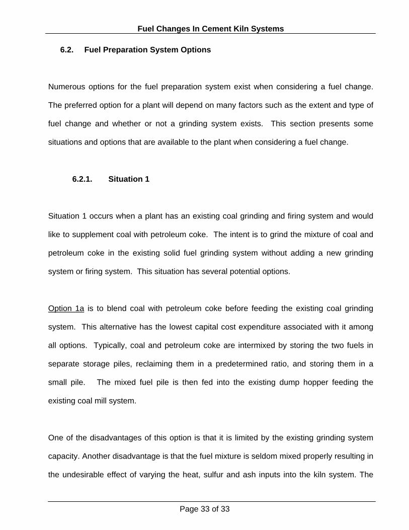
6.2. Fuel Preparation System Options
Numerous options for the fuel preparation system exist when considering a fuel change.
The preferred option for a plant will depend on many factors such as the extent and type of
fuel change and whether or not a grinding system exists. This section presents some
situations and options that are available to the plant when considering a fuel change.
6.2.1. Situation 1
Situation 1 occurs when a plant has an existing coal grinding and firing system and would
like to supplement coal with petroleum coke. The intent is to grind the mixture of coal and
petroleum coke in the existing solid fuel grinding system without adding a new grinding
system or firing system. This situation has several potential options.
Option 1a is to blend coal with petroleum coke before feeding the existing coal grinding
system. This alternative has the lowest capital cost expenditure associated with it among
all options. Typically, coal and petroleum coke are intermixed by storing the two fuels in
separate storage piles, reclaiming them in a predetermined ratio, and storing them in a
small pile. The mixed fuel pile is then fed into the existing dump hopper feeding the
existing coal mill system.
One of the disadvantages of this option is that it is limited by the existing grinding system
capacity. Another disadvantage is that the fuel mixture is seldom mixed properly resulting in
the undesirable effect of varying the heat, sulfur and ash inputs into the kiln system. The
Page 33 of 33

Fuel Changes In Cement Kiln Systems
varying heat input to the kiln will result in a higher heat consumption, reduced refractory life,
and increased downtime.
Option 1b is the same as option 1a with the addition that it considers a replacement of an
existing static classifier with a dynamic classifier, which will increase the grinding capacity
of the system. This change usually results in about 10 to 15 percent more capacity at the
same fineness or the ability to grind the fuels finer.
Option 1c is the same as option 1a with the addition of a separate petroleum coke feed bin
and weigh feeder to meter the petroleum coke along with metered coal into the mill. This
will reduce the heat, sulfur and ash input variation to the kiln.
Option 1d is the same as option 1a with the addition that it includes the modifications of
option 1b and 1c.
6.2.2. Situation 2
Situation 2 occurs when a plant has an existing coal grinding and firing system and would
like to supplement coal with petroleum coke. However, unlike situation 1, the intent is to
supplement the existing grinding capacity with a new grinding system.
Option 2a is to install a new grinding system with the grinding capacity to burn 100 percent
petroleum coke in the kiln burner. This situation offers the advantage of burning different
Page 34 of 34

Fuel Changes In Cement Kiln Systems
mixtures of fuels in the kiln and calciner, which provides the ability to maximize the
petroleum coke consumption without necessarily modifying the calciner.
6.2.3. Situation 3
Situation 3 occurs when the existing plant does not have a solid fuel grinding system and
would like to supplement or replace the existing fuel with either coal, petroleum or a mixture
of both. In this case, a new grinding system is required.
Option 3a is to install a new grinding and firing system with the capacity designed to meet
the plant desired solid fuel grinding rate, which may be 100 percent of the heat
requirements of the kiln system. This option has the highest capital cost expenditure
associated with it among all options.
7. Safety Considerations
When considering a fuel change, it is advisable to consider the safety aspects and
requirements of the new fuel. Coal is significantly more dangerous to handle than the other
fuels including petroleum coke because of its low ignition temperature and its auto-ignition
potential while stored. Several good references and guidelines are available for design
solid fuel preparation and firing systems such as the U.S. National Fire Protection Agency
(NFPA) codes and the U.S. Portland Cement Association publication “Recommendation
Guidelines for Coal System Safety.”
Page 35 of 35

Fuel Changes In Cement Kiln Systems
8. Summary
This paper has shown several considerations that are important when considering a fuel
change including the potential impacts on cement quality, on kiln design and operation, and
on the grinding and firing system. Some of these impacts may limit the extent of the fuel
change. The economic feasibility of a fuel change varies from one plant to the other;
therefore, the economic feasibility of a fuel change must be evaluated separately for each
plant.
Page 36 of 36

Fuel Changes In Cement Kiln Systems
Page 37 of 37
1 Perry, Robert H. and Green, Don W., Perry’s Chemical Engineers’ Handbook, Seventh Edition, Table 27-8 2 North American Combustion Handbook, Volume I: Combustion, Fuels, Stoichiometry, Heat Transfer, Fluid Flow, Third Edition, page 6 3 Avallone, Eugene A. and Baumeister III, Theodore, Marks’ Standard Handbook for Mechanical Engineers, Ninth Edition, page 7-19 4 North American Combustion Handbook, Volume I: Combustion, Fuels, Stoichiometry, Heat Transfer, Fluid Flow, Third Edition, page 6 5 North American Combustion Handbook, Volume I: Combustion, Fuels, Stoichiometry, Heat Transfer, Fluid Flow, Third Edition, page 6 6 Perry, Robert H. and Green, Don W., Perry’s Chemical Engineers’ Handbook, Seventh Edition, page 27-9 7 NFPA 68, Guide for Venting of Deflagration, 1994 Edition Table E-2 8 Perry, Robert H. and Green, Don W., Perry’s Chemical Engineers’ Handbook, Seventh Edition, page 27-6 9 Miller, F. M., Young, G. L. and von Seebach, M., Formation and Techniques for Control of Sulfur Dioxide and Other Sulfur Compounds in Portland Cement Kiln Systems, Draft of the U. S. Portland Cement Association R&D Serial No. 2460 10 Hewlett Peter C., Chemistry of Cement and Concrete, Fourth Edition, page 31. 11 Standard Specification for Portland Cement, U.S. ASTM C150-95a, Table 1, Standard Chemical Requirements. 12 Hewlett, Peter C., Lea’s Chemistry of Cement and Concrete, Fourth edition page 273 13 1999 Fuller Production Seminar, Drying and Grinding of Coal for Firing in Cement Kilns 14 Dr. Maas, Uwe, 100% Petroleum Coke Firing Using the Polysius PREPOL AS-CC Process, presented at the 17th Asean Federation of Cement Manufacturers in Bali, Indonesia June 2000 15 1999 Fuller Production Seminar, Drying and Grinding of Coal for Firing in Cement Kilns 16 Dr. Maas, Uwe, 100% Petroleum Coke Firing Using the Polysius PREPOL AS-CC Process, presented at the 17th Asean Federation of Cement Manufacturers in Bali, Indonesia June 2000 17 Coveney, David F. and Hicks, James K., Oxygen Enrichment For Improvements in Emissions Control While Burning Waste Fuels. 18 NFPA 68, Guide for Venting of Deflagration, 1994 Edition, Table C-2 19 Rhin, Charles, MINOX Precalciner Recent developments and applications in precalcination of any solid fuel with low NOx emission, presented at the European Cement Conference in Berlin Germany on September 12th to 15th 1999 by Technip CLE 20 Schröder. Bernhard, Petroleum Coke Grinding in a LOESCHE Roller Mill, presented at the LOESCHE America, Inc. 3rd Annual Seminar in Maimi Beach, FL


