AP1000 DOCUMENT COVER SHEET - Westinghouse … · F-AP-3.2-1 Rev. 0 AP1000 DOCUMENT COVER SHEET...
25
F-AP-3.2-1 Rev. 0 AP1000 DOCUMENT COVER SHEET TDC: Permanent File: APY: RFS#: RFS ITEM #: APIOOO DOCUMENT NO. ORIGINATING ORGANIZATION: Westinghouse Y'" APP-GW-GLN-098 TITLE: Compliance with 10CFR20.1406 REVISION NO. 0 I Page 1 of I W- & ASSIGNED TO ALTERNATE DOCUMENT NUMBER: mffqF %h'l WORK BREAKDOWN #: +to47 ,, ,- (C) WESTINGHOUSE ELECTRIC COMPANY LLC - 2007 WESTINGHOUSE CLASS 3 (NON PROPRIETARY) Class 3 Documents being transmitted to the NRC require the following two review signatures in lieu of a Form 36. ATTACHMENTS: CALCULATIONIANALYSIS REFERENCE: LEGAL REVIEW 7 DCP #/REV. INCORPORATED IN THIS DOCUMENT REVISION: WESTINGHOUSE PROPRIETARY CLASS 2 This document is the property of and contains Proprietary Informatipnowned by Westinghouse Electric Company LLC andlor its subcontractors and suppliers. It is transmitted to you in confidence and trust, and you agree to treat this document in strict accordance with the terms and conditions of the agreement undei which it was provided to you. ELECTRONIC FILENAME APP-GW-GLN-098RO.doc VERIFIER AP1000 RESPONSIBLE MANAGER Approval of the responsible manager signifies that document is complete, all required reviews are complete, electronic file is attached and document is released for use. ORIGINATOR T. K. Meneely REVIEWERS B. M. Galus Forms\AP1000 1406 TR Rev 0 cover sheet.doc ELECTRONIC FILE FORMAT - MS Word 40 7 ELECTRONIC FILE DESCRIPTION
Transcript of AP1000 DOCUMENT COVER SHEET - Westinghouse … · F-AP-3.2-1 Rev. 0 AP1000 DOCUMENT COVER SHEET...

F-AP-3.2-1 Rev. 0
AP1000 DOCUMENT COVER SHEET
TDC: Permanent File: APY:
RFS#: RFS ITEM #:
APIOOO DOCUMENT NO.
ORIGINATING ORGANIZATION: Westinghouse Y'"
APP-GW-GLN-098
TITLE: Compliance with 10CFR20.1406
REVISION NO.
0 I Page 1 of I W-
& ASSIGNED TO
ALTERNATE DOCUMENT NUMBER: mffqF %h'l WORK BREAKDOWN #: +to47 ,, ,,-
(C) WESTINGHOUSE ELECTRIC COMPANY LLC - 2007 WESTINGHOUSE CLASS 3 (NON PROPRIETARY) Class 3 Documents being transmitted to the NRC require the following two review signatures in lieu of a Form 36.
ATTACHMENTS:
CALCULATIONIANALYSIS REFERENCE:
LEGAL REVIEW
7
DCP #/REV. INCORPORATED IN THIS DOCUMENT REVISION:
WESTINGHOUSE PROPRIETARY CLASS 2 This document is the property of and contains Proprietary Informatipn owned by Westinghouse Electric Company LLC andlor its subcontractors and suppliers. It is transmitted to you in confidence and trust, and you agree to treat this document in strict accordance with the terms and conditions of the agreement undei which it was provided to you.
ELECTRONIC FILENAME
APP-GW-GLN-098RO.doc
VERIFIER
AP1000 RESPONSIBLE MANAGER
Approval of the responsible manager signifies that document is complete, all required reviews are complete, electronic file is attached and document is released for use.
ORIGINATOR
T. K. Meneely
REVIEWERS
B. M. Galus
Forms\AP1000 1406 TR Rev 0 cover sheet.doc
ELECTRONIC FILE FORMAT -
MS Word
40 7
ELECTRONIC FILE DESCRIPTION
Westinghouse Electric Company LLC P.O. Box 355
Pittsburgh, PA 15230-0355
© 2007 Westinghouse Electric Company LLC All Rights Reserved
APP-GW-GLN-098 March 2007 Revision 0
AP1000 Standard Combined License Technical Report 98
Title: Compliance with 10CFR20.1406

WESTINGHOUSE ELECTRIC COMPANY AP1000 Licensing Design Change Document Page 3 of 25
Document Number: APP-GW-GLN-098 Revision Number: 0
Title: Compliance with 10CFR20.1406
Brief Description of the change (what is being changed and why): This report summarizes the design approach and features incorporated into the AP1000 standard plant design which demonstrate compliance with 10CFR20.1406. Although this regulation was not discussed during the AP1000 Design Certification process, the AP1000 standard plant design was developed using a design philosophy which supports compliance with 10CFR20.1406, and the AP1000 incorporates numerous features which demonstrate this compliance. Compliance with 10CFR20.1406 is to a great extent demonstrated by standard plant design features. Therefore, review of applicable features at the Design Certification stage, and incorporation of applicable features and commitments into the Design Control Document, is most appropriate. This approach limits the potential for design or regulatory divergence among Combined License applicants referencing the same certified plant design. Some aspects of compliance with 10CFR20.1406 are operational and programmatic in nature. These areas are addressed in this report, and ultimately the AP1000 DCD, through the incorporation of additional Combined License Information items, which will be addressed by the Combined License applicants. I. APPLICABILITY DETERMINATION This evaluation is prepared to document that the change described above is a departure from Tier 2
information of the AP1000 Design Control Document (DCD) that may be included in plant specific FSARs without prior NRC approval.
A. Does the proposed change include a change to: 1. Tier 1 of the AP1000 Design Control
Document APP-GW-GL-700 NO YES (If YES prepare a report for
NRC review of the changes) 2. Tier 2* of the AP1000 Design Control
Document, APP-GW-GL-700 NO YES (If YES prepare a report for
NRC review of the changes) 3. Technical Specification in Chapter 16 of the
AP1000 Design Control Document, APP-GW-GL-700
NO YES (If YES prepare a report for NRC review of the changes)
B. Does the proposed change involve: 1. Closure of a Combined License Information
Item identified in the AP1000 Design Control Document, APP-GW-GL-700
NO YES (If YES prepare a COL item closure report for NRC review.)
2. Completion of an ITAAC item identified in Tier 1 of the AP1000 Design Control Document, APP-GW-GL-700
NO YES (If YES prepare an ITAAC completion report for NRC review.)
The questions above are answered no, therefore the departure from the DCD in a COL application does not
require prior NRC review unless review is required by the criteria of 10 CFR Part 52 Appendix D Section VIII B.5.b. or B.5c

WESTINGHOUSE ELECTRIC COMPANY AP1000 Licensing Design Change Document Page 4 of 25
Document Number: APP-GW-GLN-098 Revision Number: 0
Title: Compliance with 10CFR20.1406
II. TECHNICAL DESCRIPTION AND JUSTIFICATION Title 10 of the United States Code of Federal Regulations, Part 20.1406 states:
Minimization of contamination. Applicants for licenses, other than renewals, after August 20, 1997, shall describe in the application how facility design and procedures for operation will minimize, to the extent practicable, contamination of the facility and the environment, facilitate eventual decommissioning, and minimize, to the extent practicable, the generation of radioactive waste.
While the AP1000 standard plant design considered these requirements from the beginning of the plant design process, compliance with this regulation is not specifically discussed in the AP1000 DCD. Therefore, this report summarizes the plant features which demonstrate compliance with 10CFR20.1406. This report also includes DCD revisions to clarify some areas where, although the AP1000 standard plant design incorporated significant features, these features were not previously discussed or committed to in the DCD. Demonstration of compliance with 10CFR20.1406 is in many aspects a standard plant concern and should be considered on a standard plant basis. The AP1000 standard plant features to minimize contamination and radwaste and to facilitate eventual decommissioning include those shown in Table TR98-1. The contents of this table have been derived from consideration of the AP1000 design in light of decommissioning lessons learned (including NRC Memorandum ML062620355, October 10, 2006) and discussions in various industry forums.
Table TR98-1 AP1000 Features Applicable to 10CFR20.1406
Item Feature DCD Reference 1 Radioactive source terms are minimized through application of state-of-the-
art chemistry controls, which results in a minimization of contamination. The applicable chemistry controls include:
12.1.2.1 (as revised below)
Material selection, where primary plant materials have been specified to minimize cobalt and consequential corrosion products, and
4.5, 5.2, 6.1, 12.2, 12.3, Table 12.3-1
Primary coolant chemistry controls, including zinc addition and coordinated pH operation.
9.6.3 (as modified by Technical Report 32, (APP-GW-GLN-002, DCP/NRC1729))
WESTINGHOUSE ELECTRIC COMPANY AP1000 Licensing Design Change Document Page 5 of 25
Document Number: APP-GW-GLN-098 Revision Number: 0
Title: Compliance with 10CFR20.1406
Table TR98-1 AP1000 Features Applicable to 10CFR20.1406
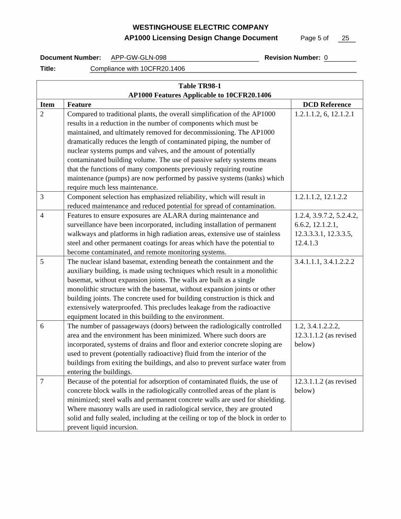
Item Feature DCD Reference 2 Compared to traditional plants, the overall simplification of the AP1000
results in a reduction in the number of components which must be maintained, and ultimately removed for decommissioning. The AP1000 dramatically reduces the length of contaminated piping, the number of nuclear systems pumps and valves, and the amount of potentially contaminated building volume. The use of passive safety systems means that the functions of many components previously requiring routine maintenance (pumps) are now performed by passive systems (tanks) which require much less maintenance.
1.2.1.1.2, 6, 12.1.2.1
3 Component selection has emphasized reliability, which will result in reduced maintenance and reduced potential for spread of contamination.
1.2.1.1.2, 12.1.2.2
4 Features to ensure exposures are ALARA during maintenance and surveillance have been incorporated, including installation of permanent walkways and platforms in high radiation areas, extensive use of stainless steel and other permanent coatings for areas which have the potential to become contaminated, and remote monitoring systems.
1.2.4, 3.9.7.2, 5.2.4.2, 6.6.2, 12.1.2.1, 12.3.3.3.1, 12.3.3.5, 12.4.1.3
5 The nuclear island basemat, extending beneath the containment and the auxiliary building, is made using techniques which result in a monolithic basemat, without expansion joints. The walls are built as a single monolithic structure with the basemat, without expansion joints or other building joints. The concrete used for building construction is thick and extensively waterproofed. This precludes leakage from the radioactive equipment located in this building to the environment.
3.4.1.1.1, 3.4.1.2.2.2
6 The number of passageways (doors) between the radiologically controlled area and the environment has been minimized. Where such doors are incorporated, systems of drains and floor and exterior concrete sloping are used to prevent (potentially radioactive) fluid from the interior of the buildings from exiting the buildings, and also to prevent surface water from entering the buildings.
1.2, 3.4.1.2.2.2, 12.3.1.1.2 (as revised below)
7 Because of the potential for adsorption of contaminated fluids, the use of concrete block walls in the radiologically controlled areas of the plant is minimized; steel walls and permanent concrete walls are used for shielding. Where masonry walls are used in radiological service, they are grouted solid and fully sealed, including at the ceiling or top of the block in order to prevent liquid incursion.
12.3.1.1.2 (as revised below)

WESTINGHOUSE ELECTRIC COMPANY AP1000 Licensing Design Change Document Page 6 of 25
Document Number: APP-GW-GLN-098 Revision Number: 0
Title: Compliance with 10CFR20.1406
Table TR98-1 AP1000 Features Applicable to 10CFR20.1406
Item Feature DCD Reference 8 Ample space for radiological work has been incorporated into the plant
design within the radiologically controlled areas of the containment, auxiliary building, annex building, and radwaste building, such that radiological work will not be required in potentially uncontrolled or unmonitored areas of the plant.
1.2, 12.1.2.1
9 The modular construction technique used results in a large number of walls in the radiologically controlled areas which are comprised of concrete contained within permanent steel forms. This left-in-place steel will be coated with paints and sealants to minimize the potential for contamination to penetrate. This not only reduces waste and background radiation during operation, but also greatly reduces decommissioning wastes, since the need for concrete scarification will be minimized.
3.8.3.1, 3.8.4.1.2, 3.8.4.5.2, 12.3.1.1.2
10 Removal and replacement of large components (steam generators, reactor coolant pumps) has been considered in detail as part of the plant design process, and adequate permanent provisions have been incorporated. This eliminates the need to construct large temporary structures, and provides for pre-established methods to prevent and control contamination during these procedures.
3.8.2.1.1, 5.4.2.2, 12.3.1.1.1
11 The use of embedded pipes has been minimized to the extent possible, consistent with maintaining radiation doses ALARA. To the extent possible, pipes have been routed in accessible areas such as dedicated pipe routing tunnels or pipe trenches, which will provide good conditions for decommissioning.
12.1.2.4 (as included in revision below)
12 Provisions for robotic and remote tooling have been made throughout the plant, with special emphasis in the primary system (the steam generators).
1.2.1.2.2, 5.1.3.2, 5.4.2.5
13 Optimized neutron shielding has been incorporated in the design of the reactor vessel insulation system. This neutron shielding will both reduce operational radiation fields and reduce the amount of surrounding material which might become activated by neutron fields during the plant life. This feature reduces the amount of material requiring special treatment during decommissioning.
12.3.2.1, Technical Report 24 (APP-GW-GLR-060; (DCP/NRC1824)
14 The selection of reactor coolant pumps without mechanical seals ensures that maintenance will be minimized. This eliminates a substantial historic need for maintenance and consequential contamination.
1.2.1.2.3, 5.1.3.3, 5.4.1

WESTINGHOUSE ELECTRIC COMPANY AP1000 Licensing Design Change Document Page 7 of 25
Document Number: APP-GW-GLN-098 Revision Number: 0
Title: Compliance with 10CFR20.1406
Table TR98-1 AP1000 Features Applicable to 10CFR20.1406
Item Feature DCD Reference 15 The spent fuel pool and connected pools are designed to eliminate
unidentified leakage to the groundwater: The walls of these pools will be constructed using modular
construction techniques, allowing higher quality than typical “in the hole” construction. The advanced welding techniques which will be employed will minimize the potential for weld failures during operation, and allow for inspection to verify weld quality.
The pools walls are made of 1/2” stainless steel plate, joined to one another with full penetration welds, and these welds will be fully inspected prior to being placed into service.
The thickness of the wall plate and the use of full penetration welds ensure that the walls will not be damaged by fuel handling, including tool manipulation and storage.
The pools are equipped with leak chases at each weld, so that the tank is effectively double-walled in the area of plate joints. This leak detection system will use piping which is adequately sized to allow testing and to minimize the potential for blockage by encrustation of precipitates (boric acid), and will facilitate removal of any such blockage.
The pool leak detection system will be zoned to allow identification of the specific area of the pool liner which is leaking, even for very small leaks.
To the extent possible, these pools are located entirely inside the auxiliary and containment building, so that any theoretical leakage from the tanks would be into the building rather than to the environment. Specifically, for pools other than a portion of the fuel transfer canal, the concrete support structure of the pools may be inspected from rooms adjacent to or below (i.e., outside) the pool.
3.8.3.1.1, 3.H.2, 12.1.2.4 (as included in revision below)
16 The radioactive waste processing systems have provisions to utilize mobile and flexible technology, where updated components can be readily installed in the radwaste building and properly interconnected with permanent systems. This approach allows for current state-of-the-art to be applied for waste processing throughout the life of the plant.
11.2, 11.4
17 The liquid radioactive waste processing system is based on ion-exchange technology, rather than the evaporation. Ion-exchange technology for radwaste has been demonstrated to generate less solid waste, and allows for flexibility in selection of resins to accommodate changing plant chemistry and other evolutions.
11.2

WESTINGHOUSE ELECTRIC COMPANY AP1000 Licensing Design Change Document Page 8 of 25
Document Number: APP-GW-GLN-098 Revision Number: 0
Title: Compliance with 10CFR20.1406
Table TR98-1 AP1000 Features Applicable to 10CFR20.1406
Item Feature DCD Reference 18 No evaporators are used in the plant design. This eliminates the potential
for local or environmental contamination through evaporator rupture disk leakage or failure.
11.2
19 The gaseous radioactive waste processing system is based upon charcoal delay beds, rather than decay tanks. Charcoal delay beds have been demonstrated to be effective in allowing adequate time for decay of radioactive gas, while not requiring a large amount of contaminated components (i.e., pressurized decay tanks) to be installed.
11.3
20 The solid waste processing system capitalizes upon the liquid waste processing system’s use of ion-exchange technology, and provides for packaging of wet wastes in high integrity containers. These containers allow for in-place dewatering and provide for a stable waste disposal technology, while at the same time providing a highly efficient packaging technique (compared to various forms of solidification which would be required for evaporator bottoms).
11.2, 11.4
21 Onsite decontamination facilities are provided for tools and small components which will routinely require decontamination. Larger components can be decontaminated in the cask washdown pit. Inclusion of these permanent facilities eliminates the need to construct temporary structures, and allows components to be decontaminated before being moved out of the radiologically controlled area of the plant.
1.2.5, 12.1.2.1, 12.1.2.2, 12.1.2.3, 12.3.1.1.1, 12.3.1.1.2, 12.3.3.3.1
22 All radioactive1 tanks are located inside appropriately designed buildings within the radiologically controlled area. Therefore, any leakage from these tanks would be into the radiogically controlled area of the plant, where adequate provisions have been made through floor drains and sealed surfaces to prevent the spread of contamination. In particular, incursion of radioactive fluid into the groundwater due to a long-term leak in one of these tanks is completely precluded.
1.2, 9.3, 11.2, 11.3, 11.4
23 No underground radioactive tanks, other than tanks located in buildings, are used in the design.
1.2, 9.3, 11.2, 11.3, 11.4
24 No flat-bottomed radioactive1 tanks are used in the design. 1.2, 9.3, 11.2, 11.3, 11.4
1 The condensate storage tank facility has the potential to become radioactive if primary to secondary leakage (i.e., a steam generator tube leak) occurs for a sustained duration. However, the potential for spread of contamination is very small; Technical Specification 3.4.7 limits operation with this type of leakage. For the purpose of this evaluation, the condensate storage tank facility is considered to be non-radioactive.
WESTINGHOUSE ELECTRIC COMPANY AP1000 Licensing Design Change Document Page 9 of 25
Document Number: APP-GW-GLN-098 Revision Number: 0
Title: Compliance with 10CFR20.1406
Table TR98-1 AP1000 Features Applicable to 10CFR20.1406
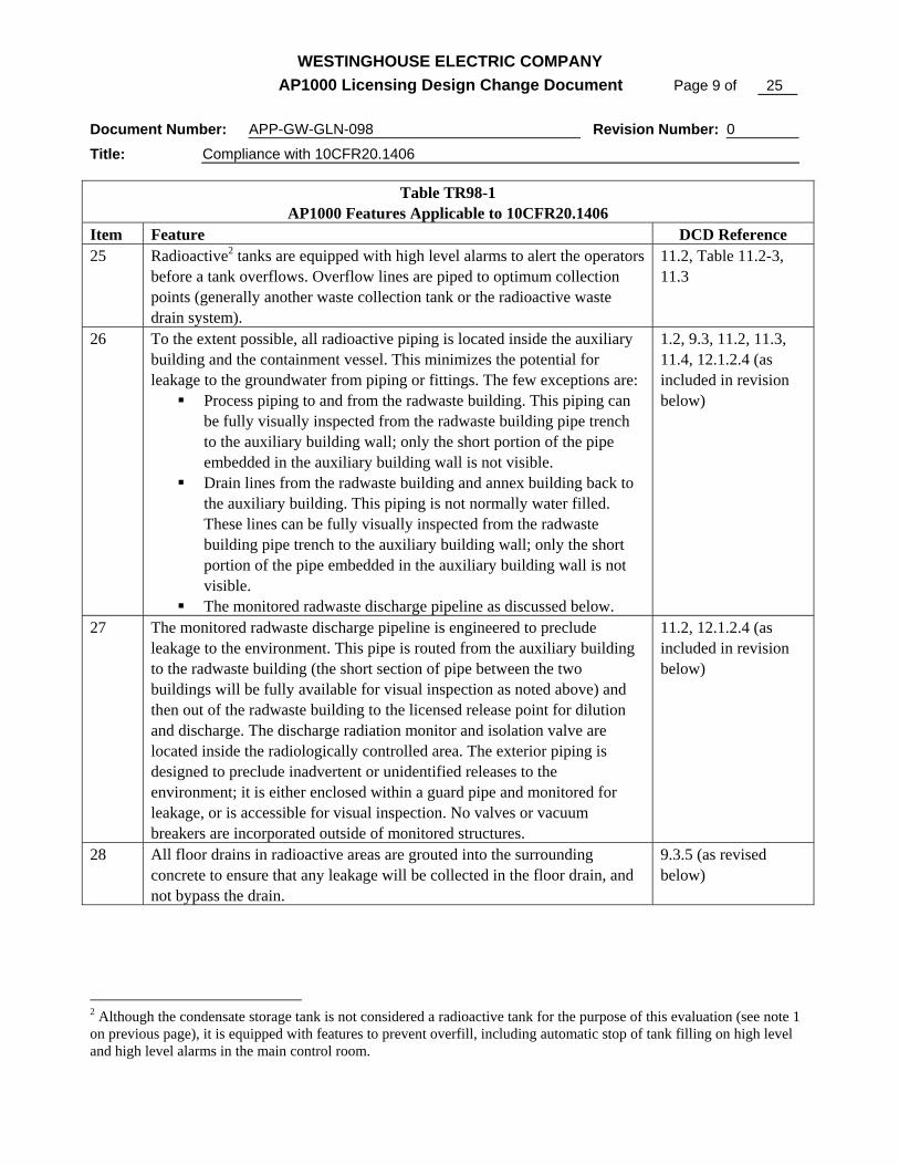
Item Feature DCD Reference 25 Radioactive2 tanks are equipped with high level alarms to alert the operators
before a tank overflows. Overflow lines are piped to optimum collection points (generally another waste collection tank or the radioactive waste drain system).
11.2, Table 11.2-3, 11.3
26 To the extent possible, all radioactive piping is located inside the auxiliary building and the containment vessel. This minimizes the potential for leakage to the groundwater from piping or fittings. The few exceptions are:
Process piping to and from the radwaste building. This piping can be fully visually inspected from the radwaste building pipe trench to the auxiliary building wall; only the short portion of the pipe embedded in the auxiliary building wall is not visible.
Drain lines from the radwaste building and annex building back to the auxiliary building. This piping is not normally water filled. These lines can be fully visually inspected from the radwaste building pipe trench to the auxiliary building wall; only the short portion of the pipe embedded in the auxiliary building wall is not visible.
The monitored radwaste discharge pipeline as discussed below.
1.2, 9.3, 11.2, 11.3, 11.4, 12.1.2.4 (as included in revision below)
27 The monitored radwaste discharge pipeline is engineered to preclude leakage to the environment. This pipe is routed from the auxiliary building to the radwaste building (the short section of pipe between the two buildings will be fully available for visual inspection as noted above) and then out of the radwaste building to the licensed release point for dilution and discharge. The discharge radiation monitor and isolation valve are located inside the radiologically controlled area. The exterior piping is designed to preclude inadvertent or unidentified releases to the environment; it is either enclosed within a guard pipe and monitored for leakage, or is accessible for visual inspection. No valves or vacuum breakers are incorporated outside of monitored structures.
11.2, 12.1.2.4 (as included in revision below)
28 All floor drains in radioactive areas are grouted into the surrounding concrete to ensure that any leakage will be collected in the floor drain, and not bypass the drain.
9.3.5 (as revised below)
2 Although the condensate storage tank is not considered a radioactive tank for the purpose of this evaluation (see note 1 on previous page), it is equipped with features to prevent overfill, including automatic stop of tank filling on high level and high level alarms in the main control room.
WESTINGHOUSE ELECTRIC COMPANY AP1000 Licensing Design Change Document Page 10 of 25
Document Number: APP-GW-GLN-098 Revision Number: 0
Title: Compliance with 10CFR20.1406
Table TR98-1 AP1000 Features Applicable to 10CFR20.1406
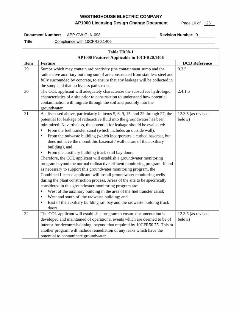
Item Feature DCD Reference 29 Sumps which may contain radioactivity (the containment sump and the
radioactive auxiliary building sump) are constructed from stainless steel and fully surrounded by concrete, to ensure that any leakage will be collected in the sump and that no bypass paths exist.
9.3.5
30 The COL applicant will adequately characterize the subsurface hydrologic characteristics of a site prior to construction to understand how potential contamination will migrate through the soil and possibly into the groundwater.
2.4.1.5
31 As discussed above, particularly in items 5, 6, 9, 15, and 22 through 27, the potential for leakage of radioactive fluid into the groundwater has been minimized. Nevertheless, the potential for leakage should be evaluated: From the fuel transfer canal (which includes an outside wall), From the radwaste building (which incorporates a curbed basemat, but
does not have the monolithic basemat / wall nature of the auxiliary building), and
From the auxiliary building truck / rail bay doors. Therefore, the COL applicant will establish a groundwater monitoring program beyond the normal radioactive effluent monitoring program. If and as necessary to support this groundwater monitoring program, the Combined License applicant will install groundwater monitoring wells during the plant construction process. Areas of the site to be specifically considered in this groundwater monitoring program are: West of the auxiliary building in the area of the fuel transfer canal; West and south of the radwaste building; and East of the auxiliary building rail bay and the radwaste building truck
doors.
12.3.5 (as revised below)
32 The COL applicant will establish a program to ensure documentation is developed and maintained of operational events which are deemed to be of interest for decommissioning, beyond that required by 10CFR50.75. This or another program will include remediation of any leaks which have the potential to contaminate groundwater.
12.3.5 (as revised below)

WESTINGHOUSE ELECTRIC COMPANY AP1000 Licensing Design Change Document Page 11 of 25
Document Number: APP-GW-GLN-098 Revision Number: 0
Title: Compliance with 10CFR20.1406
III. DCD MARK-UP
Tier 2
Table 1.8-2 (Sheet 5 of 7)
SUMMARY OF AP1000 STANDARD PLANT COMBINED LICENSE INFORMATION ITEMS
Item No. Subject Subsection
12.3-1 Administrative Controls for Radiological Protection 12.3.5.1
12.3-2 Criteria and Methods for Radiological Protection 12.3.5.2
12.3-3 Groundwater Monitoring Program 12.3.5.3
12.3-4 Record of Operational Events of Interest for Decommissioning 12.3.5.4
9.3.5.2.2 Component Description
General description and summaries of the design requirements for these components are provided below. Key equipment parameters are contained in Tables 9.3.5-1 and 11.2-2. Principal construction codes and standards and the classification applicable to the floor and equipment drainage systems are listed in Section 3.2.
Sumps and Drain Tanks
In general, the inlet drain lines to the sump or drain tank are kept submerged a minimum of 6 inches below pump shutoff level to prevent backgassing. The containment sump inlet is not submerged.
Sumps are covered to keep out debris. Covers are removable, or manholes are provided for access. The total capacity of each sump includes a 10 percent freeboard allowance to permit operation of high-high level alarms and associated controls before the overflow point is reached.
Each sump is fitted with a vent connection to exhaust potential sump gases into the room. Nonradioactive drain tanks are vented to the atmosphere. The reactor coolant drain tank is vented to the gaseous radwaste system (Section 11.3). Where necessary for the control of airborne radioactivity, the sump vents are routed to the ventilation system exhaust duct for the room.
Radioactive sumps are stainless steel construction. Nonradioactive collection sumps are constructed of concrete with corrosion resistant coating or liner.
Floor drains in radioactive areas are grouted into the surrounding concrete to collect any leakage in the floor drain, and prevent bypass of the drain.

WESTINGHOUSE ELECTRIC COMPANY AP1000 Licensing Design Change Document Page 12 of 25
Document Number: APP-GW-GLN-098 Revision Number: 0
Title: Compliance with 10CFR20.1406
Sump and Drain Tank Pumps
Sumps outside containment are provided with air diaphragm pumps mounted on the sump cover plate. Pumps are equipped with reliable, mechanical diaphragms of demonstrated acceptable design that are easy to maintain. Pumps and associated piping connections and accessories are designed for easy replacement of pump diaphragms. The containment sump pumps are described in Section 11.2. The turbine building drain tank pumps are described in subsection 9.2.9.
Valves
Air-operated valves are provided for on/off functions of air supply to the sump pump diaphragms. Swing check valves, where provided, are installed in horizontal pipe runs. Pressure control valves are provided to control air supply pressure to the sump pump diaphragms. Manual ball valves are provided for maintenance purposes.
11.2.1.3 Compliance with 10 CFR 20.1406
In accordance with the requirements of 10 CFR 20.1406 (Reference 5), the liquid radwaste system is designed to minimize, to the extent practicable, contamination of the facility and the environment, facilitate decommissioning, and minimize, to the extent practicable, the generation of radioactive waste. This is done through appropriate selection of design technology for the system, and incorporation of the ability to update the system to use best available technology throughout the life of the plant.
11.2.1.2.4 Controlled Release of Radioactivity
The liquid radwaste system provides the capability to reduce the amounts of radioactive nuclides released in the liquid wastes through the use of demineralization and time delay for decay of short-lived nuclides.
The assumed equipment decontamination factors appear in Table 11.2-5. Estimates of the radioactive source terms and annual average flow rate that will be processed in the liquid radwaste system or discharged to the environment during normal operation appear in Table 11.2-1.
Before radioactive liquid waste is discharged, it is pumped to a monitor tank. A sample of the monitor tank contents is analyzed, and the results are recorded. In this way, a record is kept of planned releases of radioactive liquid waste.
The liquid waste is discharged from the monitor tank in a batch operation, and the discharge flow rate is restricted as necessary to maintain an acceptable concentration when diluted by the circulating water discharge flow. These provisions preclude uncontrolled releases of radioactivity.

WESTINGHOUSE ELECTRIC COMPANY AP1000 Licensing Design Change Document Page 13 of 25
Document Number: APP-GW-GLN-098 Revision Number: 0
Title: Compliance with 10CFR20.1406
In addition, the discharge line contains a radiation monitor with diverse methods of stopping the discharge. The first method closes an isolation valve in the discharge line, which prevents any further discharge from the liquid radwaste system. The valve automatically closes and an alarm is actuated if the activity in the discharge stream reaches the monitor setpoint. The second method stops the monitor tank pumps.
To minimize leakage from the liquid radwaste system, the system is of welded construction except where flanged connections are required to facilitate component maintenance or to allow connection of temporary or mobile equipment. Air-operated diaphragm pumps or pumps having mechanical seals are used. These pumps minimize system leakage thereby minimizing the release of radioactive gas that might be entrained in the leaking fluid to the building atmosphere.
Provisions are made to control spills of radioactive liquids due to tank overflows. Table 11.2-3 lists the provisions for tank level indication, alarms, and overflow disposition for liquid radwaste system tanks outside containment. In addition, the radioactive waste collection tanks are located within the auxiliary building, which is well sealed and equipped with an extensive floor drain system. This eliminates the potential for undetected tank leakage to the environment, and supports compliance with 10 CFR 20.1406 (Reference 5).
The liquid radwaste system is designed so that the annual average concentration limits established by 10 CFR 20 (Appendix B, table 2, column 2) (Reference 1) for liquid releases are not exceeded during plant operation. Subsection 11.2.3 describes the calculated releases of radioactive materials from the liquid radwaste system and other portions of the liquid waste management systems resulting from normal operation.
The monitored radwaste discharge pipeline is engineered to preclude leakage to the environment. This pipe is routed from the auxiliary building to the radwaste building (the short section of pipe between the two buildings is fully available for visual inspection as noted above) and then out of the radwaste building to the licensed release point for dilution and discharge. The discharge radiation monitor and isolation valve are located inside the radiologically controlled area. The exterior piping is designed to preclude inadvertent or unidentified releases to the environment; it is either enclosed within a guard pipe and monitored for leakage, or is accessible for visual inspection. No valves or vacuum breakers are incorporated outside of monitored structures. This greatly reduces the potential for undetected leakage from this discharge to the environment at a non-licensed release point, and supports compliance with 10 CFR 20.1406 (Reference 5).

WESTINGHOUSE ELECTRIC COMPANY AP1000 Licensing Design Change Document Page 14 of 25
Document Number: APP-GW-GLN-098 Revision Number: 0
Title: Compliance with 10CFR20.1406
11.2.6 References
1. "Annual Limits on Intake (ALIs) and Derived Air Concentrations (DACs) of Radionuclides for Occupational Exposure; Effluent Concentrations; Concentrations for Release to Sewerage," 10 CFR Part 20, Appendix B, Issued by 58 FR 67657, April 28, 1995.
2. "Numerical Guides for Design Objectives and Limiting Conditions for Operation to Meet the Criterion 'As Low As Is Reasonably Achievable’ for Radioactive Material in Light-Water-Cooled Nuclear Power Reactor Effluents," 10 CFR Part 50, Appendix I.
3. "Calculation of Releases of Radioactive Materials in Gaseous and Liquid Effluents from Pressurized Water Reactors (PWR-GALE Code)," NUREG-0017, Revision 1, March 1985.
4. ANSI/ANS-55.6-1993, "Liquid Radioactive Waste Processing Systems for Light Water Reactor Plants."
5. “Minimization of contamination," 10 CFR 20.1406
11.3.1.3 Compliance with 10 CFR 20.1406
In accordance with the requirements of 10 CFR 20.1406 (Reference 4), the gaseous radwaste system is designed to minimize, to the extent practicable, contamination of the facility and the environment, facilitate decommissioning, and minimize, to the extent practicable, the generation of radioactive waste. This is done through appropriate selection of design technology for the system.
11.3.6 References
1. "Annual Limits on Intake (ALIs) and Derived Air Concentrations (DACs) of Radionuclides for Occupational Exposure; Effluent Concentrations; Concentrations for Release to Sewerage," 10 CFR Part 20, Appendix B, Issued by 58 FR 67657, April 28, 1995.
2. "Numerical Guides for Design Objectives and Limiting Conditions for Operation to Meet the Criterion >As-Low-As-Is-Reasonably-Achievable= for Radioactive Material in Light-Water-Cooled Nuclear Power Reactor Effluents," 10 CFR Part 50, Appendix I.
3. "Calculation of Releases of Radioactive Materials in Gaseous and Liquid Effluents from Pressurized Water Reactors (PWR-GALE Code)," NUREG-0017, Revision 1, March 1985.
4. “Minimization of contamination," 10 CFR 20.1406
WESTINGHOUSE ELECTRIC COMPANY AP1000 Licensing Design Change Document Page 15 of 25
Document Number: APP-GW-GLN-098 Revision Number: 0
Title: Compliance with 10CFR20.1406
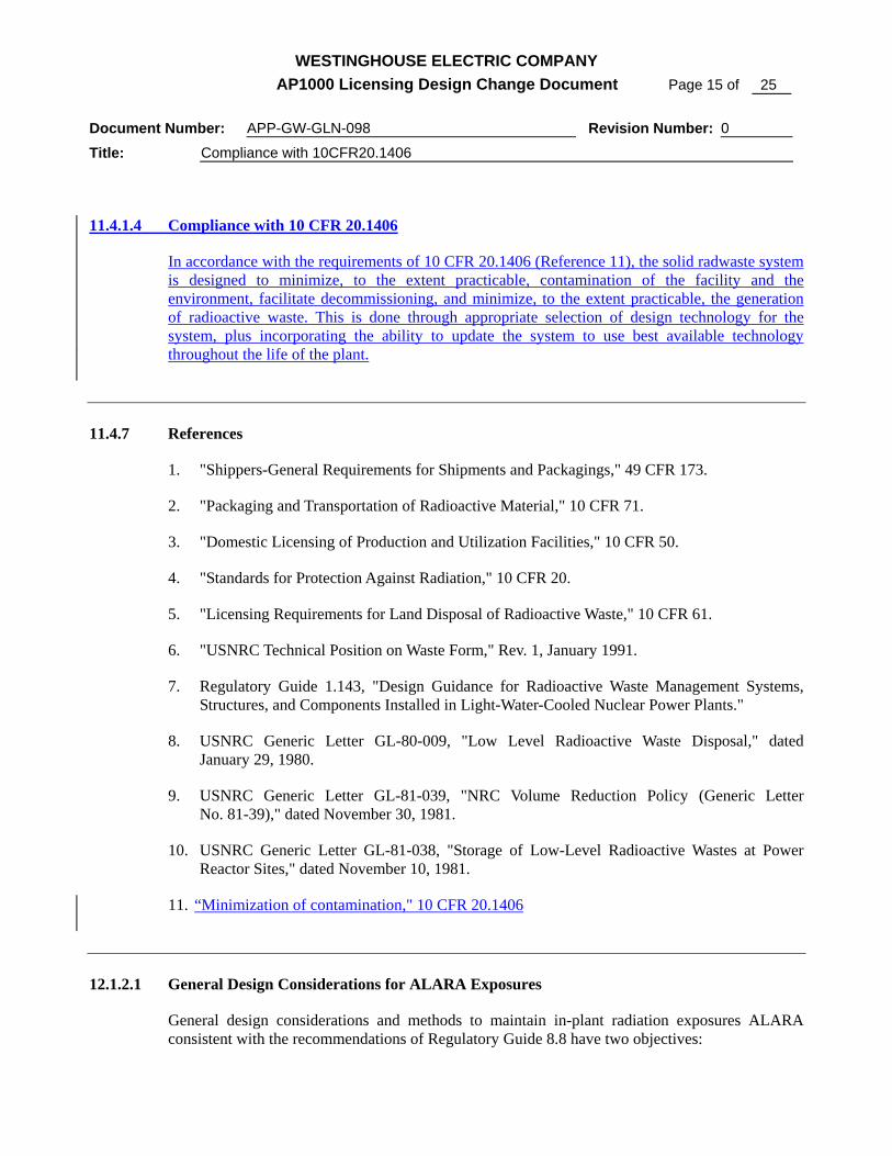
11.4.1.4 Compliance with 10 CFR 20.1406
In accordance with the requirements of 10 CFR 20.1406 (Reference 11), the solid radwaste system is designed to minimize, to the extent practicable, contamination of the facility and the environment, facilitate decommissioning, and minimize, to the extent practicable, the generation of radioactive waste. This is done through appropriate selection of design technology for the system, plus incorporating the ability to update the system to use best available technology throughout the life of the plant.
11.4.7 References
1. "Shippers-General Requirements for Shipments and Packagings," 49 CFR 173.
2. "Packaging and Transportation of Radioactive Material," 10 CFR 71.
3. "Domestic Licensing of Production and Utilization Facilities," 10 CFR 50.
4. "Standards for Protection Against Radiation," 10 CFR 20.
5. "Licensing Requirements for Land Disposal of Radioactive Waste," 10 CFR 61.
6. "USNRC Technical Position on Waste Form," Rev. 1, January 1991.
7. Regulatory Guide 1.143, "Design Guidance for Radioactive Waste Management Systems, Structures, and Components Installed in Light-Water-Cooled Nuclear Power Plants."
8. USNRC Generic Letter GL-80-009, "Low Level Radioactive Waste Disposal," dated January 29, 1980.
9. USNRC Generic Letter GL-81-039, "NRC Volume Reduction Policy (Generic Letter No. 81-39)," dated November 30, 1981.
10. USNRC Generic Letter GL-81-038, "Storage of Low-Level Radioactive Wastes at Power Reactor Sites," dated November 10, 1981.
11. “Minimization of contamination," 10 CFR 20.1406
12.1.2.1 General Design Considerations for ALARA Exposures
General design considerations and methods to maintain in-plant radiation exposures ALARA consistent with the recommendations of Regulatory Guide 8.8 have two objectives:

WESTINGHOUSE ELECTRIC COMPANY AP1000 Licensing Design Change Document Page 16 of 25
Document Number: APP-GW-GLN-098 Revision Number: 0
Title: Compliance with 10CFR20.1406
• Minimizing the necessity for access to and personnel time spent in radiation areas
• Minimizing radiation levels in routinely occupied plant areas in the vicinity of plant equipment expected to require personnel attention
Equipment and facility layouts and designs are considered for maintaining exposures ALARA during plant operations, including:
• Normal operation • Maintenance and repairs • Refueling operations and fuel storage • Inservice inspection and calibrations • Radioactive waste handling and disposal • Other anticipated operational occurrences • Decommissioning
The actual design features are described in Section 12.3. Examples of features that assist in maintaining exposures ALARA include:
• Provision of features to allow maintenance of state-of-the-art reactor coolant chemistry conditions, such that corrosion and consequential source terms are minimized. This includes pH control capability sufficient to meet current and evolving industry standards, and the ability to add zinc to the primary coolant.
• Provision of features to allow draining, flushing, and decontaminating equipment and piping
• Design of equipment to minimize the creation and buildup of radioactive material and to ease flushing of crud traps
• Provision of shielding for personnel protection during maintenance or repairs and during decommissioning
• Provision of means and adequate space for the use of movable shielding
• Separation of more highly radioactive equipment from less radioactive equipment and provision of separate shielded compartments for adjacent items of radioactive equipment
• Provision of shielded access hatches for installation and removal of plant components
• Provision of design features, such as the chemical and volume control system, to minimize crud buildup
• Provision for means and adequate space for the use of remote and robotic maintenance and inspection equipment

WESTINGHOUSE ELECTRIC COMPANY AP1000 Licensing Design Change Document Page 17 of 25
Document Number: APP-GW-GLN-098 Revision Number: 0
Title: Compliance with 10CFR20.1406
• Simplifying the plant design compared to previous pressurized water reactors with design approaches such as:
– Elimination of boron recycle – Elimination of evaporators – Use of an extended fuel cycle – Reduction in components containing radioactive fluids – Clearly and deliberately separating clean areas from potentially radioactive ones
12.1.2.4 Equipment and Facility Layout General Design Considerations for 10 CFR 20.1406
General equipment and facility layout design considerations to prevent the spread of contamination and to facilitate eventual decommissioning in accordance with 10 CFR 20.1406 include the features discussed below.
12.1.2.4.1 Piping
The use of embedded pipes is minimized to the extent possible, consistent with maintaining radiation doses ALARA.
To the extent possible, radioactive piping is located inside the auxiliary building and the containment vessel. This minimizes the potential for leakage to the groundwater from piping or fittings. The few exceptions are:
• Process piping to and from the radwaste building (which can be fully visually inspected from the radwaste building pipe trench to the auxiliary building wall)
• Drain lines from the radwaste building and annex building back to the auxiliary building (which is not normally water filled, and can also be fully visually inspected from the annex or radwaste building pipe trench to the auxiliary building wall), and
• The monitored radwaste discharge pipeline as discussed below.
The monitored radwaste discharge pipeline is engineered to preclude leakage to the environment. This pipe is routed from the auxiliary building to the radwaste building (the short section of pipe between the two buildings is fully available for visual inspection as noted above) and then out of the radwaste building to the appropriate point for dilution and discharge. The exterior piping either incorporates a guard pipe, or is available for visual inspection. No valves, vacuum breakers, or other fittings are incorporated outside of buildings.

WESTINGHOUSE ELECTRIC COMPANY AP1000 Licensing Design Change Document Page 18 of 25
Document Number: APP-GW-GLN-098 Revision Number: 0
Title: Compliance with 10CFR20.1406
12.1.2.4.2 Fuel Pool Design
The spent fuel pool and connected pools are designed to eliminate unidentified leakage to the groundwater:
• These walls of these pools are constructed using modular construction techniques, allowing higher quality than traditional construction. The advanced welding techniques which are employed minimize the potential for weld failures during operation, and allow for inspection to verify weld quality.
• The pools walls are made of 1/2” stainless steel plate, joined to one another with full penetration welds.
• The thickness of the wall plate and the use of full penetration welds prevents wall or weld damage from fuel handling operations, including tool manipulation and storage.
• The pools are equipped with leak chases at each weld. This leak detection system uses piping which is adequately sized to allow testing and to minimize the potential for blockage by encrustation of precipitates (boric acid), and facilitates removal of any such blockage.
• The pool leak detection system will be zoned to allow identification of the area of the pool liner would is leaking, even for very small leaks.
• To the extent possible, these pools are located entirely inside the auxiliary and containment building, so that any theoretical leakage from the tanks is into the building rather than having the potential for release to the environment. Specifically, for pools other than a portion of the fuel transfer canal, the concrete support structure of the pools may be inspected from rooms adjacent to or below (i.e., outside) the pool.
12.3.1.1.2 Common Facility and Layout Designs for ALARA
This subsection describes the design features utilized for standard plant process and layout situations. These features are employed in conjunction with the general equipment described in subsection 12.3.1.1.1 and include the features described in the following paragraphs.

WESTINGHOUSE ELECTRIC COMPANY AP1000 Licensing Design Change Document Page 19 of 25
Document Number: APP-GW-GLN-098 Revision Number: 0
Title: Compliance with 10CFR20.1406
Valve Modules
Selected valve modules are provided with shielded entrances for personnel protection. Floor drains are provided to control radioactive leakage. To facilitate decontamination, concrete surfaces are covered with a smooth surface coating which allows decontamination.
Piping
Pipes carrying radioactive materials are routed through controlled access areas properly zoned for that level of activity. Radioactive piping runs are analyzed to determine the potential radioactivity level and surface dose rate. Where it is necessary that radioactive piping be routed through corridors or other low radiation zone areas, shielded pipeways or distance separation are provided. Whenever practicable, valves and instruments are not placed in radioactive pipeways. Equipment compartments are used as pipeways for those pipes associated with equipment in the compartment.
When practicable, radioactive and nonradioactive piping are separated to minimize personnel exposure. Should maintenance be required, provision is made to isolate and drain radioactive piping and associated equipment.
Piping is designed to minimize low points and dead legs. Drains are provided on piping where low points and dead legs cannot be eliminated. In radioactive systems, the use of nonremovable backing rings in the piping joints is prohibited. Whenever practicable, branch lines having little or no flow during normal operation are connected above the horizontal midplane of the main pipe.
Piping which carries resin slurries is run vertically and horizontal runs carrying spent resin are sloped toward the spent resin tanks, as much as practicable. Large radius bends are utilized instead of elbows. Where sloped lines or large radius bends are impractical, adequate flush and drain capability is provided to prevent flow blockage and minimize crud traps.
The use of embedded pipes is minimized to the extent possible, consistent with maintaining radiation doses ALARA. To the extent possible pipes are routed in accessible areas such as dedicated pipe routing tunnels or pipe trenches, which provide good conditions for decommissioning.
Wall Penetrations
To minimize radiation streaming through wall penetrations, as many wall penetrations as practicable are located with offsets between the radioactive source and the normally accessible areas. If offsets are not practicable, penetrations are located as far as practicable above the floor elevation to reduce radiation exposure to personnel. If these two methods are not used, alternate means are employed, such as baffle shield walls or grouting the penetration annulus.

WESTINGHOUSE ELECTRIC COMPANY AP1000 Licensing Design Change Document Page 20 of 25
Document Number: APP-GW-GLN-098 Revision Number: 0
Title: Compliance with 10CFR20.1406
Contamination Control
Access control and traffic patterns are considered in the plant layout to reduce the spread of contamination. Equipment vents and drains from highly radioactive systems are piped directly to the collection system to minimize airborne and floor contamination. Welded piping systems are employed on radioactive systems to the maximum extent practicable to reduce system leakage and crud buildup at joints.
The number of passageways (doors) between the radiologically controlled area and the environment has been minimized. Where such doors are incorporated, systems of drains and floor and exterior concrete sloping are used to prevent (potentially radioactive) fluid from the interior of the buildings from exiting the buildings, and also to prevent surface water from entering the buildings.
Decontamination of potentially contaminated areas and equipment within the plant is facilitated by the application of epoxy paints and suitable smooth-surface coatings to the concrete floors and walls. Sloping floors with floor drains are provided in potentially contaminated areas of the plant. In addition, radioactive and potentially radioactive drains are separated from nonradioactive drains.
In radiologically controlled areas where contamination is expected, radiation monitoring equipment is provided (Section 11.5). Those systems that become highly radioactive, such as the spent resin lines in the radwaste system, are provided with flush and drain connections.
Because of the potential for adsorption of contaminated fluids, the use of concrete block walls in the radiologically controlled areas of the plant is minimized. Where such walls are used, they are fully sealed at the ceiling or top of the block in order to prevent liquid incursion.
The role of the ventilation systems in minimizing the spread of airborne contamination is described in subsection 12.3.3.
Equipment Layout
In those systems where process equipment is a major radiation source; pumps, valves, and instruments are separated from the process component. This allows servicing and maintenance of these items in reduced radiation zones. Control panels are located in low radiation zones.
Major components such as tanks, demineralizers, and filters in radioactive systems are located in shielded compartments insofar as practical. Labyrinth shields or shielding doors are provided for compartments where radiation could stream or scatter to access areas and exceed the radiation zone dose limits for those areas. For potentially high radiation components (such as ion exchangers, filters and spent resin tanks), shielded compartments with hatch openings or removable shield concrete block walls are used. Equipment in nonradioactive systems that requires lubrication is located in low radiation zones. Wherever practicable, lubrication of equipment in high radiation areas is achieved with the use of tube-type extensions to reduce exposure during maintenance.
WESTINGHOUSE ELECTRIC COMPANY AP1000 Licensing Design Change Document Page 21 of 25
Document Number: APP-GW-GLN-098 Revision Number: 0
Title: Compliance with 10CFR20.1406
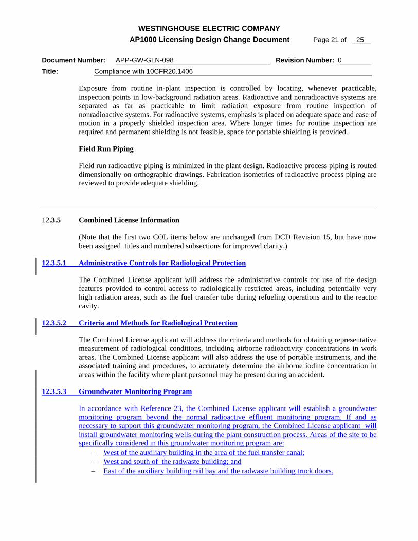
Exposure from routine in-plant inspection is controlled by locating, whenever practicable, inspection points in low-background radiation areas. Radioactive and nonradioactive systems are separated as far as practicable to limit radiation exposure from routine inspection of nonradioactive systems. For radioactive systems, emphasis is placed on adequate space and ease of motion in a properly shielded inspection area. Where longer times for routine inspection are required and permanent shielding is not feasible, space for portable shielding is provided.
Field Run Piping
Field run radioactive piping is minimized in the plant design. Radioactive process piping is routed dimensionally on orthographic drawings. Fabrication isometrics of radioactive process piping are reviewed to provide adequate shielding.
12.3.5 Combined License Information
(Note that the first two COL items below are unchanged from DCD Revision 15, but have now been assigned titles and numbered subsections for improved clarity.)
12.3.5.1 Administrative Controls for Radiological Protection
The Combined License applicant will address the administrative controls for use of the design features provided to control access to radiologically restricted areas, including potentially very high radiation areas, such as the fuel transfer tube during refueling operations and to the reactor cavity.
12.3.5.2 Criteria and Methods for Radiological Protection
The Combined License applicant will address the criteria and methods for obtaining representative measurement of radiological conditions, including airborne radioactivity concentrations in work areas. The Combined License applicant will also address the use of portable instruments, and the associated training and procedures, to accurately determine the airborne iodine concentration in areas within the facility where plant personnel may be present during an accident.
12.3.5.3 Groundwater Monitoring Program
In accordance with Reference 23, the Combined License applicant will establish a groundwater monitoring program beyond the normal radioactive effluent monitoring program. If and as necessary to support this groundwater monitoring program, the Combined License applicant will install groundwater monitoring wells during the plant construction process. Areas of the site to be specifically considered in this groundwater monitoring program are:
− West of the auxiliary building in the area of the fuel transfer canal; − West and south of the radwaste building; and − East of the auxiliary building rail bay and the radwaste building truck doors.

WESTINGHOUSE ELECTRIC COMPANY AP1000 Licensing Design Change Document Page 22 of 25
Document Number: APP-GW-GLN-098 Revision Number: 0
Title: Compliance with 10CFR20.1406
12.3.5.4 Record of Operational Events of Interest for Decommissioning
In accordance with Reference 23, the Combined License applicant will establish a program to ensure documentation of operational events which are deemed to be of interest for decommissioning, beyond that required by 10CFR50.75. This or another program will include remediation of any leaks which have the potential to contaminate groundwater.
12.3.6 References
(22 existing references not shown in markup)
23. “Minimization of contamination," 10 CFR 20.1406
IV. REGULATORY IMPACT A. FSER IMPACT
These changes have no direct impact on the text or conclusions of the AP1000 FSER, although expansion of the FSER to discuss compliance with 10CFR20.1406 on a standard plant basis is anticipated.
B. SCREENING QUESTIONS (Check correct response and provide justification for that determination
under each response) 1. Does the proposed change involve a change to an SSC that adversely affects a DCD
described design function? YES NO
The proposed changes do not involve a change to an SSC that adversely affects a DCD described design function.
2. Does the proposed change involve a change to a procedure that adversely affects how DCD described SSC design functions are performed or controlled?
YES NO
The proposed changes do not involve a change to a procedure that adversely affects how DCD described SSC design functions are performed or controlled.
3. Does the proposed activity involve revising or replacing a DCD described evaluation methodology that is used in establishing the design bases or used in the safety analyses?
YES NO
The proposed changes do not involve revising or replacing a DCD described evaluation methodology that is used in establishing the design bases or used in the safety analyses.

WESTINGHOUSE ELECTRIC COMPANY AP1000 Licensing Design Change Document Page 23 of 25
Document Number: APP-GW-GLN-098 Revision Number: 0
Title: Compliance with 10CFR20.1406
4. Does the proposed activity involve a test or experiment not described in the DCD, where an SSC is utilized or controlled in a manner that is outside the reference bounds of the design for that SSC or is inconsistent with analyses or descriptions in the DCD?
YES NO
The proposed changes do not involve a test or experiment not described in the DCD.
C. EVALUATION OF DEPARTURE FROM TIER 2 INFORMATION (Check correct response and provide
justification for that determination under each response)
10 CFR Part 52, Appendix D, Section VIII. B.5.a. provides that an applicant for a combined licensee who references the AP1000 design certification may depart from Tier 2 information, without prior NRC approval, if it does not require a license amendment under paragraph B.5.b. The questions below address the criteria of B.5.b.
1. Does the proposed departure result in more than a minimal increase in the frequency of occurrence of an accident previously evaluated in the plant-specific DCD?
YES NO
The changes described will not increase the frequency of occurrence of an accident because there is no significant increase in the probability of failure of the safety functions due to the design changes.
2. Does the proposed departure result in more than a minimal increase in the likelihood of
occurrence of a malfunction of a structure, system, or component (SSC) important to safety and previously evaluated in the plant-specific DCD?
YES NO
There are no changes which will cause an increase in the probability of an occurrence of a malfunction of any SSC important to the safety and previously evaluated in the plant specific DCD.
3. Does the proposed departure Result in more than a minimal increase in the consequences of
an accident previously evaluated in the plant-specific DCD? YES NO
The changes have no effect on the operation, performance, and pressure boundary integrity of the containment vessel. Therefore, there is no increase in the calculated release of radioactive material during postulated accident conditions.
4. Does the proposed departure result in more than a minimal increase in the consequences of
a malfunction of an SSC important to safety previously evaluated in the plant-specific DCD?
YES NO
The changes have no effect on the design functions or reliability of an SSC. Therefore there is no increase in the calculated release of radioactive material due to a malfunction of an SSC.
5. Does the proposed departure create a possibility for an accident of a different type than any
evaluated previously in the plant-specific DCD? YES NO
The changes have no effect on the operation, performance and pressure boundary integrity of the containment

WESTINGHOUSE ELECTRIC COMPANY AP1000 Licensing Design Change Document Page 24 of 25
Document Number: APP-GW-GLN-098 Revision Number: 0
Title: Compliance with 10CFR20.1406
vessel. The changes do not introduce any additional failure modes. Therefore, these changes will not result in an accident of a type different than what has already been evaluated in the DCD.
6. Does the proposed departure create a possibility for a malfunction of an SSC important to
safety with a different result than any evaluated previously in the plant-specific DCD? YES NO
The changes have no effect on the design functions of an SSC. Therefore, there are no additional failure modes or the possibility for a malfunction of an SSC important to safety with a different result than evaluated previously.
7. Does the proposed departure result in a design basis limit for a fission product barrier as
described in the plant-specific DCD being exceeded or altered? YES NO
There is no change to the design function of an SSC. Therefore, the proposed departure result does not result in a design basis limit for a fission product barrier as described in the plant-specific DCD being exceeded.
8. Does the proposed departure result in a departure from a method of evaluation described in
the plant-specific DCD used in establishing the design bases or in the safety analyses? YES NO
The methods of evaluation for the SSCs described in the plant-specific DCD are not altered by the proposed departure.
The answers to the evaluation questions above are “NO” and the proposed departure from Tier 2 does not require prior NRC review to be included in plant specific FSARs as provided in 10 CFR Part 52, Appendix D, Section VIII. B.5.b
One or more of the answers to the evaluation questions above are “YES” and the proposed change requires NRC review.
D. IMPACT ON RESOLUTION OF A SEVERE ACCIDENT ISSUE
10 CFR Part 52, Appendix D, Section VIII. B.5.a. provides that an applicant for a combined licensee who references the AP1000 design certification may depart from Tier 2 information, without prior NRC approval, if it does not require a license amendment under paragraph B.5.c. The questions below address the criteria of B.5.c.
1. Does the proposed activity result in an impact to features that mitigate severe accidents. If the answer is Yes answer Questions 2 and 3 below.
YES NO
2. Is there is a substantial increase in the probability of a severe accident such that a particular
severe accident previously reviewed and determined to be not credible could become credible?
YES NO
N/A

WESTINGHOUSE ELECTRIC COMPANY AP1000 Licensing Design Change Document Page 25 of 25
Document Number: APP-GW-GLN-098 Revision Number: 0
Title: Compliance with 10CFR20.1406
3. Is there is a substantial increase in the consequences to the public of a particular severe accident previously reviewed?
YES NO
N/A
The answers to the evaluation questions above are “NO” or are not applicable and the proposed departure from Tier 2 does not require prior NRC review to be included in plant specific FSARs as provided in 10 CFR Part 52, Appendix D, Section VIII. B.5.c
One or more of the he answers to the evaluation questions above are “YES” and the proposed change requires NRC review.
E. SECURITY ASSESSMENT
1. Does the proposed change have an adverse impact on the security assessment of the AP1000.
The design changes will not alter barriers or alarms that control access to protected areas of the plant. The changes will not alter requirements for security personnel.
YES NO