Antenna Based SDMA Schemes for Wireless Communications · PDF fileSmartwaves International...
30
Smartwaves International Antenna Based SDMA Schemes for Wireless Communications Dr. J. R. Sanford Smart Waves International 3385 Scott Boulevard Santa Clara, CA 95054 Tel. (415) 412 8694 [email protected]
-
Upload
phungkhanh -
Category
Documents
-
view
222 -
download
1
Transcript of Antenna Based SDMA Schemes for Wireless Communications · PDF fileSmartwaves International...
Smartwaves International
Antenna Based SDMASchemes for Wireless
Communications
Dr. J. R. Sanford
Smart Waves International3385 Scott Boulevard
Santa Clara, CA 95054
Tel. (415) 412 8694

2
Assumptions
• Wireless communication, that is not line of sight,has a limited usable spectrum due to propagationissues (0-3GHz)
• There is no limit to the amount of data we willwish to send
• Therefore, this spectrum must be used asefficiently as possible– All degrees of freedom must be used optimally

3
Outline
• Environment
• Goal
• Space Diversity Combining
• Multiple Beam Arrays
• Digital Beam Forming
• Frequency Scanned Systems
• Holographic Beam Forming
• Conclusions
Overview
New
}}

4
Angular Spread
• Angular spread is a function of base stationlocation, distance and environment
5
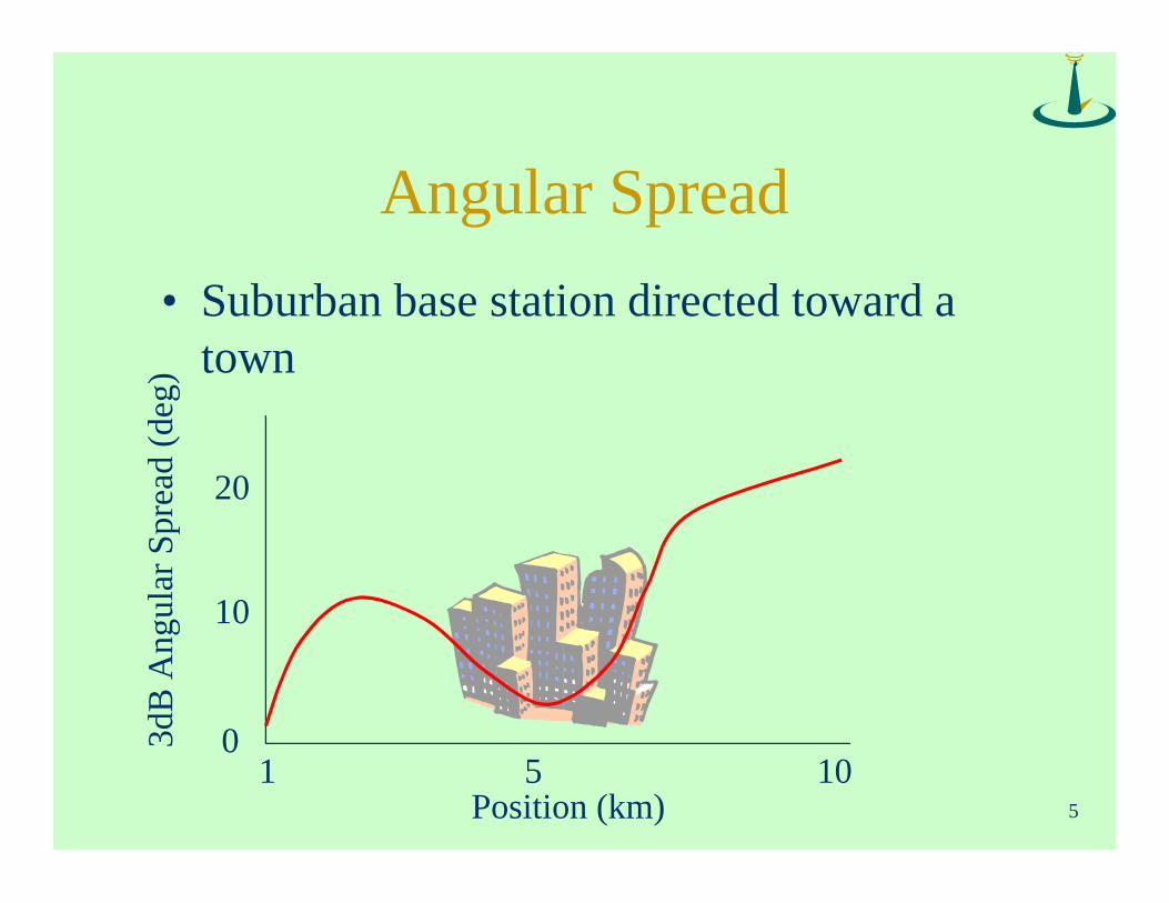
Angular Spread
• Suburban base station directed toward atown
3dB
Ang
ular
Spr
ead
(deg
)
Position (km)
0
10
20
1 105

6
Angular Spread
• Signal Loss over
Los
s Fa
ctor
3dB Angular Spread (deg)
1
500
1000
1 2010
1
r2
BernRapperswil

7
Link Directivity
• Signal Loss over
Los
s (d
B)
Average/Peak (dB)
0
15
30
-25 -15-20
1
r2
BernRapperswil

8
Interference Rejection
• Resolution is directly related to interferencerejection
Res
olut
ion
Angular Spread
0
15m
30m
0 2010

9
Smart Antenna Systems
• Main Goals:– Increase Capacity
– Increase Range
– Eliminate Down Time
• Additional Advantages– Emergency Tracking
– Jamming Suppression

10
Degrees of Freedom
time
spac
e
GSM
frequency
CDMA
• GSM, AMS, CDMA all reside in two dimensions
• Space is four dimensional (x,y,z, polarization)
• Code is a subset of the time-frequency space
op timal
6 Dimensional SpaceKnowns:Propagation environmentHardware performanceComponent costRegulations

11
Optimization
ASP Algorithm
Antenna
Channel Model
Polarization
Power AmplifierFiltering
DSPModulation
Best System A/D Converter
Rx and Tx Bands
LNA
Site Planning
Demodulator

12
Present Standard Trends
• UMTS plans services and features
• Wide Band CDMA is the leading futurestandard– TD-CDMA as a subset for smart antennas
• Data over Voice
• Down link limits performance– why not allocate more bandwidth to the down
link
13
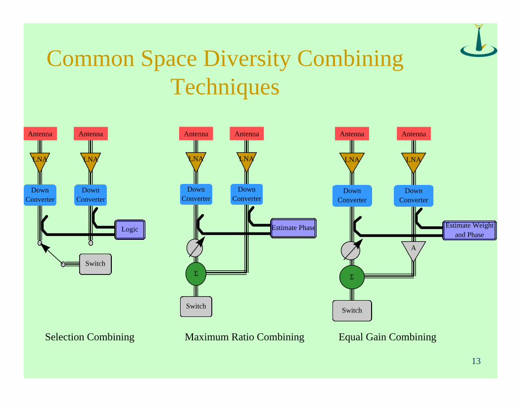
Common Space Diversity CombiningTechniques
Antenna
LNA
DownConverter
Antenna
LNA
DownConverter
Logic
Switch
Antenna
LNA
DownConverter
Antenna
LNA
DownConverter
Estimate Weightand Phase
Switch
A
Σ
Antenna
LNA
DownConverter
Antenna
LNA
DownConverter
Estimate Phase
Switch
Σ
Selection Combining Equal Gain CombiningMaximum Ratio Combining

14
Space Diversity
• Configuration can be considered 2 element array
• Optimized when antennas are maximally spaced
– more than 2 wavelengths
– decorrelated noise
• Maximum ratio is preferred in basic combiners
• A dual polarized antenna may be used instead oftwo antennas
– polarization diversity

15
Butler Matrix Fed Array
l
(n-1)l
l
Port n1 3 4 5 6 7
Transceiverband 2
Butler Matrix
Phase Front
Element Element Element Element Element Element Element Element
(n-1)l
• Combined at RF
• Elements are within awavelength

16
f2
f6f7 f3f5 f4
f1f8
Beam Distribution
Cell Boundary

17
Butler Matrix Fed Array
• Utilization– Sectorize a cell into n-cells with increased link energy
• 3dB gain increase
– Combined beams eliminate gaps• 6dB gain increase
– Cross channel interference is reduced• 10dB improvement
– Frequency hopping dramatically improves worst casefading
• Application– Low density sites with large cells

18
RF Phased Array
Calibration Network
LNAPA
3 3
Calibration Network
LNAPA
3 3

19
RF Scanning Array
• All channels are directed together
• Best for broad band TDMA packeted information

20
Digital Beam Forming Array
Calibration Network
A/D D/A
Transceiver
Computer
DSP
DSP
Elements
• Combined at IF
• Elements arewithin awavelength

21
SDMA Concept
Channel 1
• Gain
• Interference suppresion
• Fade compensation

22
Digital Beam Forming Array
• Total independent channels
• Channel bandwidth limited– DSP speed relates to bandwidth
– Wide band CDMA?
• Allows distributed power– One low power amp per element
• Very good interference rejection– channels(elements-1) “nulls”

23
Frequency Scanned Array
Transceiver
f2
24
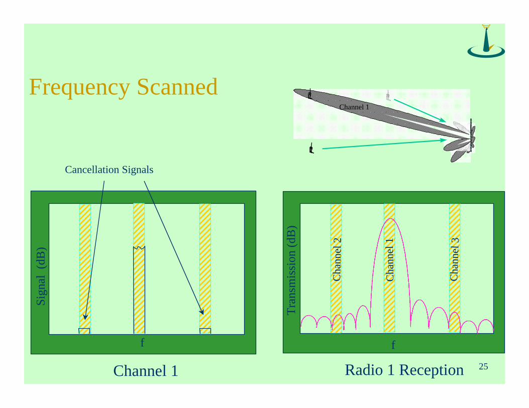
Frequency Scanned System
• Employs frequency tracking mobiles– Radio chooses the optimal channel band
• Improves range– High gain frequency scanned antennas are easily
constructed
• Adaptive nulling through frequency channelselection– Each direction corresponds to a frequency
• Best used in wide band systems
25
Frequency Scanned
Sign
al (
dB)
f
Tra
nsm
issi
on (
dB)
f
Cancellation Signals
Channel 1 Radio 1 Reception
Cha
nnel
3
Cha
nnel
1
Cha
nnel
2
Channel 1

26
Holographic Communications Concept

27
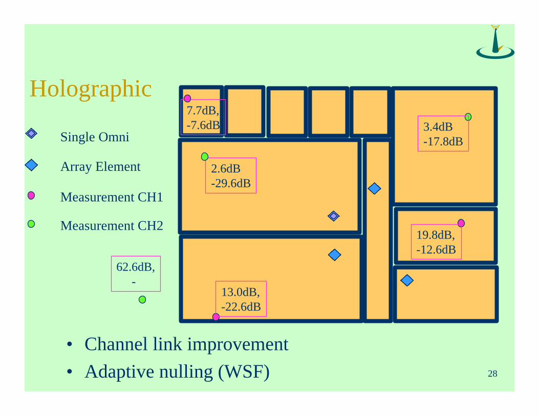
Holographic
• VLBI applied to wireless communications
• Local signal maxima are formed on transmit
• Fades are uncorrelated at the base stations
• Offers the maximum capacity and range increaseof any conceivable system
• Allows tracking, and jamming suppression (GPSlike)
28
Holographic7.7dB,-7.6dB
2.6dB-29.6dB
62.6dB, -
13.0dB,-22.6dB
19.8dB,-12.6dB
3.4dB-17.8dB
• Channel link improvement
• Adaptive nulling (WSF)
Single Omni
Array Element
Measurement CH1
Measurement CH2

29
Optimized Hardware Control
ASP Algorithm
Channel Model
Power Amplifier
DSP
Modulation
GA Channel Optimization A/D Converter
Rx and Tx Bands
LNA
Demodulator
• Create the best link through optimized hardwarecontrol
Power Control

30
Conclusions
• We will use SDMA schemes as they become costeffective
• SDMA implementation becomes more costeffective as new DSPs become available
• SDMA will be necessary to improve capacity
• TDMA (ATM) combines nicely with SDMA
• Holographic techniques provide the greatestpotential