Performance analysis for SDMA mmWave systems: using an ...
10
DRO Deakin Research Online, Deakin University’s Research Repository Deakin University CRICOS Provider Code: 00113B Performance analysis for SDMA mmWave systems: using an approximate closed-form solution of downlink sum-rate Citation: Bai, Lin, Li, Tian, Xiao, Zhenyu and Choi, Jinho 2017, Performance analysis for SDMA mmWave systems: using an approximate closed-form solution of downlink sum-rate, IEEE access, vol. 5, pp. 15641-15649. DOI: http://www.dx.doi.org/10.1109/ACCESS.2017.2734739 © 2017, IEEE Reproduced within the terms of the IEEE OAPA (Open Access Publishing Agreement). Downloaded from DRO: http://hdl.handle.net/10536/DRO/DU:30114520
Transcript of Performance analysis for SDMA mmWave systems: using an ...

DRO Deakin Research Online, Deakin University’s Research Repository Deakin University CRICOS Provider Code: 00113B
Performance analysis for SDMA mmWave systems: using an approximate closed-form solution of downlink sum-rate
Citation: Bai, Lin, Li, Tian, Xiao, Zhenyu and Choi, Jinho 2017, Performance analysis for SDMA mmWave systems: using an approximate closed-form solution of downlink sum-rate, IEEE access, vol. 5, pp. 15641-15649.
DOI: http://www.dx.doi.org/10.1109/ACCESS.2017.2734739
© 2017, IEEE
Reproduced within the terms of the IEEE OAPA (Open Access Publishing Agreement).
Downloaded from DRO: http://hdl.handle.net/10536/DRO/DU:30114520
Received July 4, 2017, accepted July 25, 2017, date of publication August 1, 2017, date of current version August 22, 2017.
Digital Object Identifier 10.1109/ACCESS.2017.2734739
Performance Analysis for SDMA mmWaveSystems: Using an Approximate Closed-FormSolution of Downlink Sum-RateLIN BAI1, (Senior Member, IEEE), TIAN LI1,2, (Student Member, IEEE),ZHENYU XIAO1,2, (Senior Member, IEEE), AND JINHO CHOI3, (Senior Member, IEEE)1School of Electronic and Information Engineering, Beihang University, Beijing 100191, China2Beijing Laboratory for General Aviation Technology, Beihang University, Beijing 100191, China3School of Electrical Engineering and Computer Science, Gwangju Institute of Science and Technology, Gwangju 61005, South Korea
Corresponding author: Zhenyu Xiao ([email protected])
This work was supported by the National Natural Science Foundation of China under Grant 61571025,Grant 61231011, and Grant 61231013.
ABSTRACT In this paper, we analyze the performance of downlink transmission in a space divisionmultiple access (SDMA) millimeter-wave (mmWave) system with beam selection, where antenna arraysare considered at a base station (BS) and users. Under the assumption of limited scattering environment,we propose a simplified approach to analyze the downlink performance of the SDMA system. In this scheme,the throughput for each BS beam is approximated by a binary random variable for tractable analysis andan approximate closed-form solution for the downlink sum rate is derived. It is shown that the predictedthroughputs by the proposed method reasonably agree with simulation results.
INDEX TERMS Space division multiple access (SDMA), millimeter wave (mmWave), antenna arrays,performance analysis, binary random variable.
I. INTRODUCTIONThe millimeter-wave (mmWave) band, which can provide alarge available spectral resources [1]–[4], has been widelystudied for the next generation cellular system, namely 5G,to meet the high-speed wireless service requirements [5].Compared with ultra high frequency (UHF) bands employedin existing cellular systems, signals transmitted over anmmWave channel may experience high path loss [6]–[8].Thus, it is generally expected to have few paths in mmWaveband [1], [9]–[11]. The resulting environment is referred to aslimited scattering environment as opposed to rich scatteringenvironment that is typical in UHF bands.
In space division multiple access (SDMA) systems, dif-ferent downlink transmission strategies have been studiedin UHF bands [12]–[14], where beamforming at a base sta-tion (BS) plays a significant role in compensating for thehigh propagation attenuation and improving spectral effi-ciency [15]–[20]. For beamforming in mmWave systems,antenna arrays with a large number of elements are gener-ally equipped at the BS and users to extend communicationrange [1], [21]. Unfortunately, due to the large-scale antennaarrays, the implementation of radio frequency (RF) hard-ware has become one of the main difficulties in mmWave
systems [22]. In such a case, hybrid beamforming usinganalog and digital beamformers has been studied to solve thisimplementation constraint [23], [24]. With a small numberof RF chains, [11] proposed a hybrid precoder using analogphase shifters and digital precoders under limited scatteringenvironments. In [25], Rajashekar and Hanzo considers ahybrid beamformer for a more practical system, where thehybrid beamforming matrices are designed by employing afinite input alphabet instead of Gaussian symbols. As an alter-native approach, beam selection with a set of pre-determinedbeams can also be considered [26]. One of the advantages ofbeam selection lies in the low-complexity of beamformingcompared with conventional hybrid approaches. Specifically,beam selection inmmWave systems is a special case of hybridbeamforming, in which the digital beamformer can be seen asan analog beam selector.
The above mentioned works mainly consider beamform-ing methods for mmWave systems, where performance wasvaluated by simulation. To the best of our knowledge, fewstudies have been focused on the performance analysis ofmmWave systems with beamforming, especially on deriv-ing closed-form expression of achievable sum-rate. Differentfrom these works, in this paper we analyze the performance
VOLUME 5, 20172169-3536 2017 IEEE. Translations and content mining are permitted for academic research only.
Personal use is also permitted, but republication/redistribution requires IEEE permission.See http://www.ieee.org/publications_standards/publications/rights/index.html for more information.
15641
L. Bai et al.: Performance Analysis for SDMA mmWave Systems
of downlink SDMA in an mmWave system with beam selec-tion [12]. The performance analysis is challenging due tothe interaction between user beamforming [27], [28] andBS beamforming with pre-determined codebooks for beamselection. Therefore, with certain assumptions for tractableanalysis, we propose approximate closed-form solutions forthe downlink sum-rate under different channel conditions,where the throughput of each BS beam is approximatedby a binary random variable. With these manipulations, wederive an approximate closed-form expression for down-link throughput in SDMA mmWave systems. Numericalresults show that the analytical sum-rate performance derivedby the proposed method reasonably agree with simulationresults.
The rest of the paper is organized as follows. Section IIpresents the system model for SDMA mmWave systemsusing antenna arrays and discusses the downlink sum-ratewith user beam selection strategy. Furthermore, some nec-essary assumptions for tractable analysis are also stud-ied. In order to apply the simplified approach to analyzethe performance, the effectiveness of user beamformingis discussed in Section III. In Section IV, approximateclosed-form solutions for downlink throughput with differentchannel coefficient conditions are derived and the effect of thenumber of BS beams on downlink performance is analyzed.Simulation results are presented and discussed in Section Vand the paper is concluded in Section VI.Notation: Vectors and matrices are presented by lowercase
and uppercase bold letters, respectively. The transpose andHermitian transpose are denoted by superscripts T and H,respectively. Present byCn×m as the n×m-dimensional com-plex space. The statistical expectation is presented by E[·].While CN (a,R) denotes the distribution of circularly sym-metric complex Gaussian (CSCG) random vectors with meanvector a and covariance matrix R.
II. ANALYSIS OF USER BEAM SELECTIONIN mmWave SYSTEMSIn this section, we consider an opportunistic SDMAwith userbeam selection based on [12].
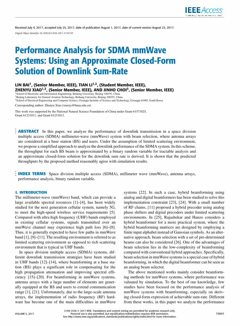
A. SYSTEM MODELThroughout the paper, we consider a frequency-divisionduplexing (FDD) based cellular system constitutes one BSand U users. As shown in Fig. 1, antenna arrays with LB andLU elements are equipped at the BS and users, respectively.Although hybrid beamforming implementation is employedin mmWave systems, the computational complexity is stillhigh as full channel state information (CSI) feedback andprecoding are required. Thus, in this paper, we assume thatthe beams are formed by analog beamformers with pre-determined phases (i.e., a hybrid beamformer where thebeamforming is implemented in RF domain and the digitalprecoding is merely a beam selector) at the BS. In this case,beamforming becomes beam selection with a set of pre-determined beams.
FIGURE 1. System model for the SDMA mmWave system with beamselection.
Let V be the set of beams at the BS and |V| = K . Thedownlink pilot signal from the BS array is given by
z =K∑k=1
vkdk (1)
where vk is the k-th beam in V and dk is the pilot signal forthe k-th beam. Hence, the received signal vector at user ubecomes
yu = Huz+ nu
=
K∑k=1
Huvkdk + nu (2)
whereHu ∈ CLU×LB denotes the downlink channel to user u,and nu ∼ CN (0, σ 2I) denotes the background noise vector.Moreover, we assume E[|dk |2] = P/K , i.e., the total transmitpower is P.According to [9] and [29], mmWave channels would be
characterized by few strong paths. Thus, the channel matrix,Hu, can be found as
Hu =
Q∑p=1
hu,pb(ψu,p)aH(θu,p) (3)
where Q is the number of paths between the BS and auser. For simplicity, we assume that the number of paths isthe same for all users. As mentioned above, due to limitedscattering in mmWave channels, Q is not large and usually2 or 3 on average [9]. Let hu,p denote the channel coefficientof the p-th path. The angle-of-arrival (AoA) and angle-of-departure (AoD) are presented by ψu,p and θu,p, respectively.In this paper, we assume that ψu,p and θu,p are indepen-dent and uniformly distributed. Here, b(ψ) ∈ CLU×1 anda(θ ) ∈ CLB×1 denote the array response vectors (ARVs)of the user and BS arrays, respectively. For the sake ofsimplicity, we consider a uniform linear array (ULA) withhalf-wavelength spacing and the ARVs are normalized as||b(ψ)|| = ||a(θ )|| = 1. In this case, the ARV of theBS becomes
a(θ ) =1√LB
[1 e−jπ sin θ . . . e−j(LB−1)π sin θ ]T. (4)
15642 VOLUME 5, 2017
L. Bai et al.: Performance Analysis for SDMA mmWave Systems
Although the ULA is considered in the paper, it is straight-forward to extend the channel model and beam selection withuniform planar array (UPA) [11], because similar assump-tions as S1)- S2) in Subsection II-C could also be satisfiedto simplify the analysis.
It is noteworthy that multiple mini-slots of random orthog-onal beams are used in [12] for beam selection under arich scattering environment. To find the best set of randomorthogonal beams for a given group of users, multiple sets ofbeams are generated and transmitted over multiple mini-slots.Thus, it is desirable to have more sets of random orthogonalbeams or more mini-slots for a better performance. However,since the pilot signaling overhead increases with the numberof mini-slots, there is a trade-off and an optimal number ofmini-slots can be found [12]. In mmWave channels, as men-tioned earlier, due to limited scattering environments, multi-ple sets of beams may not be useful to understand the systemperformance which has been studied in [30]. In this paper,with a set of K near orthogonal beams that are obtained bythe ARV of the BS with quantized AoDs, the pilot trainingcan be carried out as above. Note that in our case, we do notuse multiple mini-slots (we only use one slot).
B. USER BEAM SELECTION AND DOWNLINKTHROUGHPUTDue to the implementation difficulties and computationalcomplexity, in this paper, we consider analog beamformerwith fixed-beams at users.
Suppose that each user has a codebook of pre-determinedbeamforming vectors, which is denoted by Wu =
{wu,1, . . . ,wu,NU }, where NU represents the number ofbeams at a user. From (2), the beamformer output of theq-th beam at user u becomes
su,q;k = wHu,qyu
= wHu,qHuvkdk +
∑l 6=k
wHu,qHuvldl + wH
u,qnu. (5)
Throughout the paper, we assume ||vk || = ||wu,q|| = 1 fornormalization purposes.
At user u, from (5), the signal-to-interference-plus-noiseratio (SINR) of BS beam k at user beam q can be written as
Au,q;k =|wH
u,qHuvk |2
K/ρ +∑
l 6=k |wHu,qHuvl |2
(6)
where ρ = P/σ 2. In (6), the interference power term,∑l 6=k |w
Hu,qHuvl |2, is regarded as the inter-beam inter-
ference (IBI) results from the other beams. Thus, theSINR related to the k-th BS beam at user u is given by
Au;k = max1≤q≤NU
Au,q;k . (7)
According to [12], based on the users’ feedback signals(BS beam indexes and the corresponding SINR values), theBS allocates the k-th beam to the user with the highest SINR.
Then, the downlink throughput can be computed as
C =K∑k=1
log2
(1+ max
1≤u≤UAu;k
). (8)
While the beam selection approach is based on [12], itsperformance analysis is different from that in [12] due tovarious reasons. One of them is the existence of user arrays.Another is the different channel environment. In the follow-ing analysis, we consider the beam selection under limitedscattering environments.
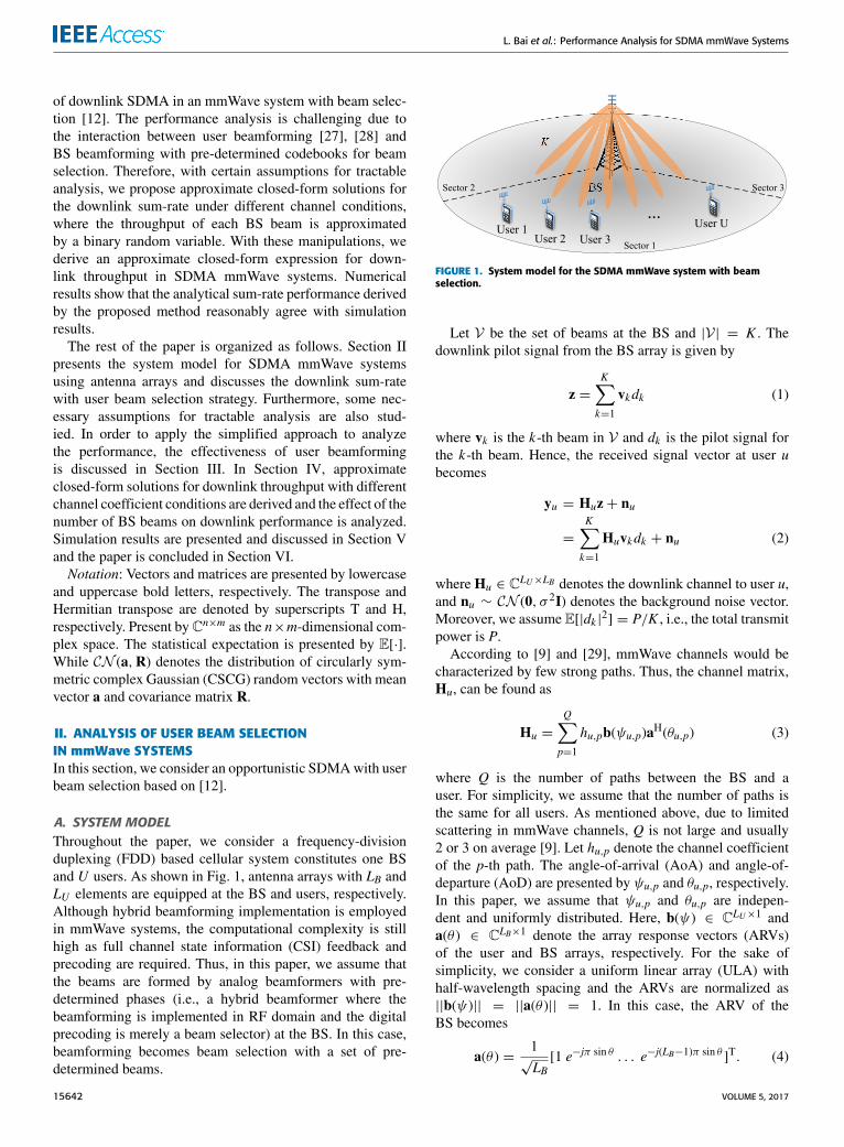
C. SIMPLIFICATIONS USING mmWave CHARACTERSFor tractable reasons, we have the following assumptionsaccording to the characters of mmWave.S1) Denote 9q as the set of possible AoAs of the received
signals related to the q-th user beam. Let ∪q9q = 9,and we assume that
|wHu,qb(ψ)|
2=
{1, if ψ ∈ 9q;
εU , otherwise(9)
where εU � 1 and 9j ∩9q = ∅, j 6= q. Moreover, 9q’sare equally divided and q = 1, . . . ,NU .
As discussed in S1), the entire space of the AoAs can becovered by user beams, {wu,1, . . . ,wu,NU }, shown in Fig. 2.Clearly, if ψ /∈ 9q, we have |wH
u,qb(ψ)|2= εU � 1. Note
that wu,q would be the ARV of the center AoA of 9q. In thiscase, for ψ ∈ 9q, the claim that |wH
u,qb(ψ)|2= 1 in S1) may
not be true, but the approximation would be reasonable sinceLU is expected to be large in mmWave systems.
FIGURE 2. An illustration of the set of user beams.
S2) The beamforming vectors at the BS are generated as
|aH(θ )vk |2 =
{1, if θ ∈ 2k ;
εB, otherwise(10)
where 2k denotes the set of the AoDs for the k-thBS beam. Again,2k ’s are equally divided. Furthermore,2k ∩2m = ∅, k 6= m, and ∪k2k = 2, where 2 is theset of all possible AoDs.
The rationale of S2) is similar to that of S1) and is omittedhere.
VOLUME 5, 2017 15643

L. Bai et al.: Performance Analysis for SDMA mmWave Systems
III. THE EFFECT OF USER BEAMFORMINGIn this section, based on the discussions in Subsection II-C,we focus on the role of the user beamformer with the channelmatrix described in (3) and propose a simplified model foruser beamforming.
Under S1) - S2), we have the following definition.Definition 1: With Q paths, suppose that
θu,1 ∈ 21, θu,2 ∈ 22, . . . , θu,Q ∈ 2Q. (11)
It is claimed that user beamforming is effective if
|wHu,ib(ψu,j)|
2=
{1, i = j;εU , i 6= j,
for i = 1, . . . ,NU and j = 1, . . . ,Q. (12)
Otherwise, it is ineffective.For illustration purpose, the case of ineffective beamform-
ing with Q = 2 is shown in Fig. 3, where θu,1 ∈ 21 andθu,2 ∈ 22. We can find that |wH
u,jb(ψu,1)|2=
|wHu,jb(ψu,2)|
2= 1 based on S1). Thus, the spatial diversity
at the user side cannot be fully exploited which results inineffective user beamforming.
FIGURE 3. An illustration of ineffective beamforming with Q = 2.
Denote by Pe(Q) the probability of effective user beam-forming with Q paths. Then, we have the following results.Lemma 1: Under S1) - S2), we assume that θu,i, for i =
1, . . . ,Q, where Q < K, is in a different 2l , l = 1, . . . ,K.For any Q ≥ 2, Pe(Q) becomes
Pe(Q) =
∏Q−1i=1 (NU − i)
NQ−1U
. (13)
Proof: As we assume that Q paths are located in dif-ferent BS beams (suppose that Q = 2, if θu,1 ∈ 91 andθu,2 ∈ 91, the two paths are merged, this becomes the caseof Q = 1). Let ψu,1 ∈ 91, we have Pr (ψu,2 /∈ 91) =
NU−1NU
.If ψu,2 ∈ 92, we have Pr (ψu,3 /∈ 91 ∪92) =
Nu−2NU
. Thus,
the probability of (12) becomes∏Q−1i=1 (NU−i)
NQ−1U
.
As a result, the probability of effective user beamformingdecreases with Q for a large NU . To illustrate it intuitively,the probabilities of effective user beamforming with differ-ent values of Q are shown in Fig. 4, where K = 20 andNU = {40, 50}.
FIGURE 4. The probability of effective user beamforming with Q.
Clearly, we can find that the probability of the effectivebeamforming decreases with Q which confirms (13). More-over, it is noteworthy that the value of the probability isprohibitively high under limited scattering environment andPe(Q) = 0.9263 with Q = 3 when NU = 40. That is, witha high probability, there might be a user beam q that satisfies|wH
u,qb(ψu,p)|2= 1 for a p of |aH(θu,p)vk |2 = 1. This is
regarded as effective user beamforming. With the approxi-mation of effective user beamforming, we can simplify theperformance analysis of downlink transmission in mmWavesystems.
IV. PERFORMANCE ANALYSIS OF DOWNLINKSDMA mmWave SYSTEMSIn this section, we discuss the downlink throughput for theperformance analysis. According to (13), we assume thatthe user beamforming is effective. In this case, with certaincharacters of mmWave, we model the channel coefficient as aconstant value and derive an approximate downlink through-put by using a binary random model of the SINRs. After that,we consider the impact of the number of BS beams on thedownlink throughput. Moreover, to validate the performancetrend over K , we also analyze the system performance withRayleigh fading channel coefficients and provide a closed-form expression of the achievable sum-rate.
A. AN APPROXIMATE CLOSED-FORM SOLUTIONFOR DOWNLINK SUM-RATETo derive the approximate closed-form expression of thesystem achievable throughput, we first consider the followingassumption.
S3) The channel gains are the same for all u and p [29], i.e.,
|hu,p|2 = |h|2 = 1. (14)
In S3), considering the independent path loss of differentpaths, the channel coefficient in (14) is not generally true.However, with this assumption, we can analyze the impact
15644 VOLUME 5, 2017

L. Bai et al.: Performance Analysis for SDMA mmWave Systems
of K on system performance intuitively. Moreover, when thedistances between the BS and users are almost the same, suchas air-based network communications, it would be reasonableto set the channel coefficient as a constant.Lemma 2: Under S1) - S3), Au;k can be formulated as a
random variable given by
Au;k
{≥ µ w.p. Pµ;≤ λ w.p. 1− Pµ
(15)
where µ = 1K/ρ+(K−1)εB
, λ = 1K−1 , and Pµ = 1− e−
QK .
Proof: Suppose that there exits at least one path p suchthat |aH(θu,p)vk |2 = 1 for a user. The resulting SINR in (7)is given by
Au;k
= maxq
|wHu,q∑Q
p=1 hu,pb(ψu,p)aH(θu,p)vk |2
K/ρ +∑
l 6=k |wHu,q∑Q
p=1 hu,pb(ψu,p)aH(θu,p)vl |2
=|∑Q
p=1 hu,paH(θu,p)vk |2
K/ρ +∑
l 6=k |∑Q
p=1 hu,paH(θu,p)vl |2
≥ maxp
|aH(θu,p)vk |2
K/ρ +∑
l 6=k |aH(θu,p)vl |2, (16)
because there is a user beam, say user beam q, that satisfies|wH
u,qb(ψu,p)|2= 1 for a p of |aH(θu,p)vk |2 = 1. Due to S2),
we have
Au;k ≥ µ =1
K/ρ + (K − 1)εB. (17)
The probability of (17) is equivalent to the probability thatthere is at least one path that belongs to the k-th beam, whichcan be calculated as
Pµ = 1− Pr(|aH(θu,p)vk |2 ≤ εB for all p)
= 1−(K − 1K
)Q. (18)
Since K−1K can be written as 2log2(1−
1K ) and log2(1 + x) ≈
x log2 e when x ≈ 0, (18) becomes
Pµ = 1−(2log2(1−
1K ))Q
≈ 1−(2−
1K log2 e
)Q= 1− e−
QK (19)
where the inequality tends to equality increasingly with K .On the other hand, if the k-th BS beam is not included in all
paths of a user, the SINR becomes either Au;k =εB
K/ρ+(K−1)εBor εB
K/ρ+1+(K−2)εB(i.e., one of |aH(θu,p)vl |2, l 6= k is 1),
which satisfies
Au;k ≤ λ =1
K − 1. (20)
The corresponding probability is 1− Pµ.
According to Lemma 2, for tractable analysis, Au;k wouldbe modeled as a binary random variable with Au;k ∈ {µ, λ}and the Au;k ’s are independent. Thus, the throughput for eachBS beam, Xk , becomes a binomial random variable given by
Xk = max1≤u≤U
log2(1+ Au;k )
=
{log2(1+ µ), w.p. Pµ(U );log2(1+ λ), w.p. 1− Pµ(U )
(21)
where
Pµ(U ) = 1− (1− Pµ)U
≈ 1− e−QUK . (22)
From (8), since C =∑K
k=1 Xk , the mean of C can becalculated as
E[C] =K∑k=1
E [Xk ]
= K[log2(1+ µ)Pµ(U )+ log2(1+ λ)(1− Pµ(U ))
]≈ K log2
(1+
1K/ρ + (K − 1)εB
)(1− e−
QUK ).
(23)
Note that the approximation is reasonable since log2(1 + λ)can be ignored with a sufficiently large K .
B. THROUGHPUT ANALYSISIn UHF band, under a rich scattering environment, the down-link throughput can be optimized by adjusting the number oftraining mini-slots in [12]. As mentioned earlier, in mmWaveband, due to limited scattering environments, we do not needto have multiple mini-slots of random orthogonal beams.There is a single slot of K beams. To see the impact of thenumber of beams, K , on the average throughput in (23), weconsider the case that K ≤ U . It follows
E[C] = K log2
(1+
1K/ρ + (K − 1)εB
)(1− e−
QUK )
≈ K log2
(1+
1K/ρ + (K − 1)εB
)≈ K log2
(1+
1ξK
)(24)
where ξ = 1ρ+ εB that can be considered as a constant
since εB � 1 with near orthogonal beams. Let R̄(K ) =
K log2(1+ 1
ξK
). The derivative of the average throughput
with respect to K becomes
ddK
R̄(K ) =1ln 2
(ln(1+
1ξK
)−
11+ ξK
)≥
1ln 2
(1
1+ ξK−
11+ ξK
)= 0 (25)
where the inequality is due to ln (1+ x) ≥ x1+x for x ≥ 0.
Thus, R̄(K ) is a nondecreasing function of K . That is, the
VOLUME 5, 2017 15645
L. Bai et al.: Performance Analysis for SDMA mmWave Systems
more near orthogonal BS beams generated simultaneously(i.e., more angular resolution), the higher the sum throughputin downlink SDMA mmWave systems. However, the limit ofR̄(K ) is bounded as
limK→∞
R̄(K ) =log2 eξ
= log2 eρ
1+ ρεB. (26)
It is noteworthy that when ρ → ∞, the performance wouldbe limited by εB. That is, if ρ →∞, the asymptotic sum-rateapproaches log2 e
εB. Thus, a small εB is generally desirable.
C. PERFORMANCE ANALYSIS UNDER RAYLEIGHFADING CHANNELSWithout loss of generality, in this subsection, we discuss thesystem performance with small-scale fading channel coeffi-cient. As in [11], the channel coefficients, hu,p’s, are assumedto be i.i.d. CN (0, 1) here. For convenience, we use h insteadof hu,p in the following analysis. Then, Xk in (21) becomes
Xk =
log2(1+
|h|2
K/ρ + (K − 1)εB|h|2), w.p. Pµ(U );
log2(1+1
K − 1), w.p. 1−Pµ(U ),
(27)
and the average sum-rate is derived as
E[C] =K∑k=1
E [Xk ]
= KE[log2
(1+
|h|2
K/ρ + (K − 1)εB|h|2
)]Pµ(U )
+ K log2(1+
1K − 1
)(1− Pµ(U ))
≈ KE[log2
(1+
|h|2
K/ρ + (K − 1)εB|h|2
)]Pµ(U )
= K∫∞
0log2
(1+
xK/ρ + (K − 1)εBx
)e−xdxPµ(U )
(28)
where f (x) = e−x is the probability density function (pdf)of |h|2.Next, we compute the closed-form of E[C]. Based on
Jensen’s inequality, the expectation in (28) is upper-boundedby [31]
E[log2
(1+
|h|2
K/ρ + (K − 1)εB|h|2
)]≤ log2
(1+ E
[|h|2
K/ρ + (K − 1)εB|h|2
])= log2
(1+
∫∞
0
xe−x
K/ρ + (K − 1)εBxdx)
= log2
(1+
γ
ω2 eγωEi
(−γ
ω
)+
1ω
)(29)
where γ = K/ρ, ω = (K − 1)εB, and Ei(x) =−∫∞
−x e−r/rdr .
Thus, an approximate closed-form of E[C] is given by
E[C] =K∑k=1
E [Xk ]
≤ K log2
(1+
γ
ω2 eγωEi
(−γ
ω
)+
1ω
)Pµ(U ). (30)
Note that although the closed-form expression is an upper-bound, the performance difference is marginal which can beobserved in Section V.
V. SIMULATION RESULTS AND ANALYSISIn simulations, we consider users in a sector as illustratedin Fig. 1. Thus, we have 2 = (−60◦, 60◦). Moreover,according to (4), the BS beams, {vl}, are generated as
vl = a(θ̂l), l = 1, . . . ,K (31)
where θ̂l = lδθ+θoffset. Here, δθ = 120◦K and θoffset = −60◦−
δθ2 . In addition, we set 9 = (−60◦, 60◦) and the signal-to-noise ratio (SNR), ρ, to 20 dB at any user.
Note that in S2), we have |aH(θ )vl |2 = 1 if θ ∈ 2l , whichis not true in general with the beams in (31). Thus, we needto modify this assumption with the results from the designedbeams. If θ ∈ 2l , we have |aH(θ )vl |2 = G, where
G =maxθ∈2l |a
H(θ )vl |2 +minθ∈2l |aH(θ )vl |2
2≤ 1. (32)
The value of εB in (17) is the cross-correlation found from thebeams in (31).
For comparison, seven different simulations1 are consid-ered as follows:• ‘‘Analytical’’: simulations using (23);• ‘‘R-analytical’’: simulations using (23) with the modi-fied gain in (32);
• ‘‘Idealized analytical’’: simulations using (24);• ‘‘Analytical-Ray’’: simulations using (28);• ‘‘Analytical-Ray-CF’’: simulations using (30);• ‘‘Realistic’’: simulations using opportunistic beamform-ing strategy with the channel coefficient in (14);
• ‘‘Realistic-Ray’’: simulations using opportunistic beam-forming strategy within Rayleigh fading channels.
Figs. 5 and 6 show simulation results for the throughputswhen K varies from 12 to 30 with U = 30 and U = 50,respectively, where LB = 40 and LU = 10. Obviously, theaverage throughput with U = 50 is higher than that withU = 30 since more multiuser gain can be exploited, whichcan also be illustrated through (22) and (23). Note that theperformance obtained by the three analytical methods closelyfollows the ‘‘Realistic’’ curve, especially for a large numberof users and moderate value of K that satisfies K ≤ U .
1Note that the simplifications in Subsection II-C are not considered whenrunning ‘‘Realistic’’ and ‘‘Realistic-Ray’’ simulations.
15646 VOLUME 5, 2017

L. Bai et al.: Performance Analysis for SDMA mmWave Systems
FIGURE 5. Average throughput with variable K with U = 30 when Q = 3and NU = 20.
FIGURE 6. Average throughput with variable K with U = 50 when Q = 3and NU = 20.
We observe that the curve of ‘‘Analytical’’ is slightly higherthan that of the ‘‘R-analytical’’ as G ≤ 1 from (32). In addi-tion, ‘‘Idealized analytical’’ provides the highest throughputas we set εB = 0.001 which cannot be a constant in the realscenario. However, it might be a reasonable approximationwith a moderate value of K and the trend agrees with that ofthe realistic one.
In Fig. 7, we present the simulation results for differentnumbers of user beams with U = 30. For ‘‘Realistic’’curve, clearly, the throughput increases with NU . Moreover,the improvement becomes less significant when NU is suf-ficiently large, since the user beamforming becomes suffi-ciently effective. That is to say, the analytical method withthe simplifications in Sections III and IV can provide a goodapproximation for the performance analysis if users employa sufficiently large number of beams. Again, the throughputfrom ‘‘Idealized analytical’’ provides the highest one as weset εB = 0.001.
When U = 50, as shown in Fig. 8, the performance gapbetween realistic and analytical methods becomes less signif-icant sincemoremultiuser gain can be exploitedwhich results
FIGURE 7. Average throughput with variable NU when K = 16, U = 30,LB = 40, and LU = 10.
FIGURE 8. Average throughput with variable NU when K = 16, U = 50,LB = 40, and LU = 10.
in an increasing probability of the effective beamformingamong all users. In summary, the proposed analytical methodcan provide reasonable results when NU is large and U ≥ K .To see the impact of Q on the effectiveness of the pro-
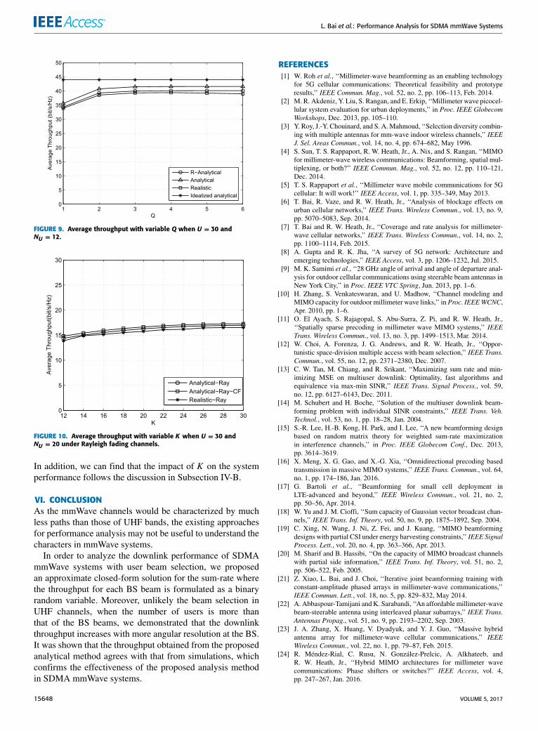
posed method, simulations are carried out with K = 16and the results are shown in Fig. 9. It is noteworthy thatthe performance of two analytical curves closely follows thatof the ‘‘Realistic’’ one which confirms the effectiveness ofthe proposed method under limited scattering environment.In addition, the further increase of Q (Q > 4 in Fig. 9) doesnot provide a growing throughput in simulations since moreIBI is involved.
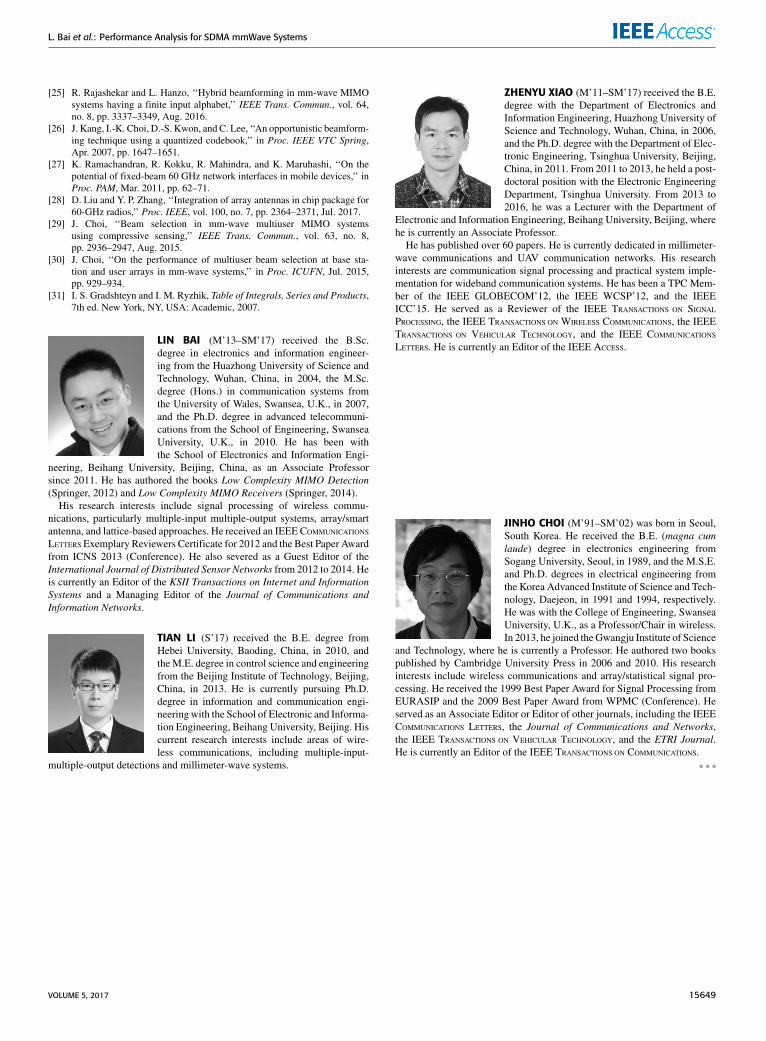
For the performance with Rayleigh fading channel coef-ficients, the simulations results are shown in Fig. 10. Obvi-ously, the results of analytical curves closely follow those ofthe numerical simulation and the average throughput growswith K . Furthermore, it can be clearly observed that there isno noticeable performance difference between ‘‘Analytical-Ray’’ and ‘‘Analytical-Ray-CF’’, which indicates that (30)could be used as an approximate closed-form expression.
VOLUME 5, 2017 15647
L. Bai et al.: Performance Analysis for SDMA mmWave Systems
FIGURE 9. Average throughput with variable Q when U = 30 andNU = 12.
FIGURE 10. Average throughput with variable K when U = 30 andNU = 20 under Rayleigh fading channels.
In addition, we can find that the impact of K on the systemperformance follows the discussion in Subsection IV-B.
VI. CONCLUSIONAs the mmWave channels would be characterized by muchless paths than those of UHF bands, the existing approachesfor performance analysis may not be useful to understand thecharacters in mmWave systems.
In order to analyze the downlink performance of SDMAmmWave systems with user beam selection, we proposedan approximate closed-form solution for the sum-rate wherethe throughput for each BS beam is formulated as a binaryrandom variable. Moreover, unlikely the beam selection inUHF channels, when the number of users is more thanthat of the BS beams, we demonstrated that the downlinkthroughput increases with more angular resolution at the BS.It was shown that the throughput obtained from the proposedanalytical method agrees with that from simulations, whichconfirms the effectiveness of the proposed analysis methodin SDMA mmWave systems.
REFERENCES[1] W. Roh et al., ‘‘Millimeter-wave beamforming as an enabling technology
for 5G cellular communications: Theoretical feasibility and prototyperesults,’’ IEEE Commun. Mag., vol. 52, no. 2, pp. 106–113, Feb. 2014.
[2] M. R. Akdeniz, Y. Liu, S. Rangan, and E. Erkip, ‘‘Millimeter wave picocel-lular system evaluation for urban deployments,’’ in Proc. IEEE GlobecomWorkshops, Dec. 2013, pp. 105–110.
[3] Y. Roy, J.-Y. Chouinard, and S. A.Mahmoud, ‘‘Selection diversity combin-ing with multiple antennas for mm-wave indoor wireless channels,’’ IEEEJ. Sel. Areas Commun., vol. 14, no. 4, pp. 674–682, May 1996.
[4] S. Sun, T. S. Rappaport, R. W. Heath, Jr., A. Nix, and S. Rangan, ‘‘MIMOfor millimeter-wave wireless communications: Beamforming, spatial mul-tiplexing, or both?’’ IEEE Commun. Mag., vol. 52, no. 12, pp. 110–121,Dec. 2014.
[5] T. S. Rappaport et al., ‘‘Millimeter wave mobile communications for 5Gcellular: It will work!’’ IEEE Access, vol. 1, pp. 335–349, May 2013.
[6] T. Bai, R. Vaze, and R. W. Heath, Jr., ‘‘Analysis of blockage effects onurban cellular networks,’’ IEEE Trans. Wireless Commun., vol. 13, no. 9,pp. 5070–5083, Sep. 2014.
[7] T. Bai and R. W. Heath, Jr., ‘‘Coverage and rate analysis for millimeter-wave cellular networks,’’ IEEE Trans. Wireless Commun., vol. 14, no. 2,pp. 1100–1114, Feb. 2015.
[8] A. Gupta and R. K. Jha, ‘‘A survey of 5G network: Architecture andemerging technologies,’’ IEEE Access, vol. 3, pp. 1206–1232, Jul. 2015.
[9] M. K. Samimi et al., ‘‘28 GHz angle of arrival and angle of departure anal-ysis for outdoor cellular communications using steerable beam antennas inNew York City,’’ in Proc. IEEE VTC Spring, Jun. 2013, pp. 1–6.
[10] H. Zhang, S. Venkateswaran, and U. Madhow, ‘‘Channel modeling andMIMO capacity for outdoor millimeter wave links,’’ in Proc. IEEEWCNC,Apr. 2010, pp. 1–6.
[11] O. El Ayach, S. Rajagopal, S. Abu-Surra, Z. Pi, and R. W. Heath, Jr.,‘‘Spatially sparse precoding in millimeter wave MIMO systems,’’ IEEETrans. Wireless Commun., vol. 13, no. 3, pp. 1499–1513, Mar. 2014.
[12] W. Choi, A. Forenza, J. G. Andrews, and R. W. Heath, Jr., ‘‘Oppor-tunistic space-division multiple access with beam selection,’’ IEEE Trans.Commun., vol. 55, no. 12, pp. 2371–2380, Dec. 2007.
[13] C. W. Tan, M. Chiang, and R. Srikant, ‘‘Maximizing sum rate and min-imizing MSE on multiuser downlink: Optimality, fast algorithms andequivalence via max-min SINR,’’ IEEE Trans. Signal Process., vol. 59,no. 12, pp. 6127–6143, Dec. 2011.
[14] M. Schubert and H. Boche, ‘‘Solution of the multiuser downlink beam-forming problem with individual SINR constraints,’’ IEEE Trans. Veh.Technol., vol. 53, no. 1, pp. 18–28, Jan. 2004.
[15] S.-R. Lee, H.-B. Kong, H. Park, and I. Lee, ‘‘A new beamforming designbased on random matrix theory for weighted sum-rate maximizationin interference channels,’’ in Proc. IEEE Globecom Conf., Dec. 2013,pp. 3614–3619.
[16] X. Meng, X. G. Gao, and X.-G. Xia, ‘‘Omnidirectional precoding basedtransmission in massive MIMO systems,’’ IEEE Trans. Commun., vol. 64,no. 1, pp. 174–186, Jan. 2016.
[17] G. Bartoli et al., ‘‘Beamforming for small cell deployment inLTE-advanced and beyond,’’ IEEE Wireless Commun., vol. 21, no. 2,pp. 50–56, Apr. 2014.
[18] W. Yu and J. M. Cioffi, ‘‘Sum capacity of Gaussian vector broadcast chan-nels,’’ IEEE Trans. Inf. Theory, vol. 50, no. 9, pp. 1875–1892, Sep. 2004.
[19] C. Xing, N. Wang, J. Ni, Z. Fei, and J. Kuang, ‘‘MIMO beamformingdesigns with partial CSI under energy harvesting constraints,’’ IEEE SignalProcess. Lett., vol. 20, no. 4, pp. 363–366, Apr. 2013.
[20] M. Sharif and B. Hassibi, ‘‘On the capacity of MIMO broadcast channelswith partial side information,’’ IEEE Trans. Inf. Theory, vol. 51, no. 2,pp. 506–522, Feb. 2005.
[21] Z. Xiao, L. Bai, and J. Choi, ‘‘Iterative joint beamforming training withconstant-amplitude phased arrays in millimeter-wave communications,’’IEEE Commun. Lett., vol. 18, no. 5, pp. 829–832, May 2014.
[22] A. Abbaspour-Tamijani andK. Sarabandi, ‘‘An affordablemillimeter-wavebeam-steerable antenna using interleaved planar subarrays,’’ IEEE Trans.Antennas Propag., vol. 51, no. 9, pp. 2193–2202, Sep. 2003.
[23] J. A. Zhang, X. Huang, V. Dyadyuk, and Y. J. Guo, ‘‘Massive hybridantenna array for millimeter-wave cellular communications,’’ IEEEWireless Commun., vol. 22, no. 1, pp. 79–87, Feb. 2015.
[24] R. Méndez-Rial, C. Rusu, N. González-Prelcic, A. Alkhateeb, andR. W. Heath, Jr., ‘‘Hybrid MIMO architectures for millimeter wavecommunications: Phase shifters or switches?’’ IEEE Access, vol. 4,pp. 247–267, Jan. 2016.
15648 VOLUME 5, 2017
L. Bai et al.: Performance Analysis for SDMA mmWave Systems
[25] R. Rajashekar and L. Hanzo, ‘‘Hybrid beamforming in mm-wave MIMOsystems having a finite input alphabet,’’ IEEE Trans. Commun., vol. 64,no. 8, pp. 3337–3349, Aug. 2016.
[26] J. Kang, I.-K. Choi, D.-S. Kwon, and C. Lee, ‘‘An opportunistic beamform-ing technique using a quantized codebook,’’ in Proc. IEEE VTC Spring,Apr. 2007, pp. 1647–1651.
[27] K. Ramachandran, R. Kokku, R. Mahindra, and K. Maruhashi, ‘‘On thepotential of fixed-beam 60 GHz network interfaces in mobile devices,’’ inProc. PAM, Mar. 2011, pp. 62–71.
[28] D. Liu and Y. P. Zhang, ‘‘Integration of array antennas in chip package for60-GHz radios,’’ Proc. IEEE, vol. 100, no. 7, pp. 2364–2371, Jul. 2017.
[29] J. Choi, ‘‘Beam selection in mm-wave multiuser MIMO systemsusing compressive sensing,’’ IEEE Trans. Commun., vol. 63, no. 8,pp. 2936–2947, Aug. 2015.
[30] J. Choi, ‘‘On the performance of multiuser beam selection at base sta-tion and user arrays in mm-wave systems,’’ in Proc. ICUFN, Jul. 2015,pp. 929–934.
[31] I. S. Gradshteyn and I. M. Ryzhik, Table of Integrals, Series and Products,7th ed. New York, NY, USA: Academic, 2007.
LIN BAI (M’13–SM’17) received the B.Sc.degree in electronics and information engineer-ing from the Huazhong University of Science andTechnology, Wuhan, China, in 2004, the M.Sc.degree (Hons.) in communication systems fromthe University of Wales, Swansea, U.K., in 2007,and the Ph.D. degree in advanced telecommuni-cations from the School of Engineering, SwanseaUniversity, U.K., in 2010. He has been withthe School of Electronics and Information Engi-
neering, Beihang University, Beijing, China, as an Associate Professorsince 2011. He has authored the books Low Complexity MIMO Detection(Springer, 2012) and Low Complexity MIMO Receivers (Springer, 2014).
His research interests include signal processing of wireless commu-nications, particularly multiple-input multiple-output systems, array/smartantenna, and lattice-based approaches. He received an IEEE COMMUNICATIONS
LETTERS Exemplary Reviewers Certificate for 2012 and the Best Paper Awardfrom ICNS 2013 (Conference). He also severed as a Guest Editor of theInternational Journal of Distributed Sensor Networks from 2012 to 2014. Heis currently an Editor of the KSII Transactions on Internet and InformationSystems and a Managing Editor of the Journal of Communications andInformation Networks.
TIAN LI (S’17) received the B.E. degree fromHebei University, Baoding, China, in 2010, andtheM.E. degree in control science and engineeringfrom the Beijing Institute of Technology, Beijing,China, in 2013. He is currently pursuing Ph.D.degree in information and communication engi-neering with the School of Electronic and Informa-tion Engineering, Beihang University, Beijing. Hiscurrent research interests include areas of wire-less communications, including multiple-input-
multiple-output detections and millimeter-wave systems.
ZHENYU XIAO (M’11–SM’17) received the B.E.degree with the Department of Electronics andInformation Engineering, Huazhong University ofScience and Technology, Wuhan, China, in 2006,and the Ph.D. degree with the Department of Elec-tronic Engineering, Tsinghua University, Beijing,China, in 2011. From 2011 to 2013, he held a post-doctoral position with the Electronic EngineeringDepartment, Tsinghua University. From 2013 to2016, he was a Lecturer with the Department of
Electronic and Information Engineering, Beihang University, Beijing, wherehe is currently an Associate Professor.
He has published over 60 papers. He is currently dedicated in millimeter-wave communications and UAV communication networks. His researchinterests are communication signal processing and practical system imple-mentation for wideband communication systems. He has been a TPC Mem-ber of the IEEE GLOBECOM’12, the IEEE WCSP’12, and the IEEEICC’15. He served as a Reviewer of the IEEE TRANSACTIONS ON SIGNAL
PROCESSING, the IEEE TRANSACTIONS ON WIRELESS COMMUNICATIONS, the IEEETRANSACTIONS ON VEHICULAR TECHNOLOGY, and the IEEE COMMUNICATIONS
LETTERS. He is currently an Editor of the IEEE ACCESS.
JINHO CHOI (M’91–SM’02) was born in Seoul,South Korea. He received the B.E. (magna cumlaude) degree in electronics engineering fromSogang University, Seoul, in 1989, and the M.S.E.and Ph.D. degrees in electrical engineering fromthe Korea Advanced Institute of Science and Tech-nology, Daejeon, in 1991 and 1994, respectively.He was with the College of Engineering, SwanseaUniversity, U.K., as a Professor/Chair in wireless.In 2013, he joined theGwangju Institute of Science
and Technology, where he is currently a Professor. He authored two bookspublished by Cambridge University Press in 2006 and 2010. His researchinterests include wireless communications and array/statistical signal pro-cessing. He received the 1999 Best Paper Award for Signal Processing fromEURASIP and the 2009 Best Paper Award from WPMC (Conference). Heserved as an Associate Editor or Editor of other journals, including the IEEECOMMUNICATIONS LETTERS, the Journal of Communications and Networks,the IEEE TRANSACTIONS ON VEHICULAR TECHNOLOGY, and the ETRI Journal.He is currently an Editor of the IEEE TRANSACTIONS ON COMMUNICATIONS.
VOLUME 5, 2017 15649