Annexure ‘A’ - CPWDcpwd.gov.in/WriteReadData/speci_materials_cir/26218.pdf · d. The electrical...
49
Transcript of Annexure ‘A’ - CPWDcpwd.gov.in/WriteReadData/speci_materials_cir/26218.pdf · d. The electrical...

Annexure ‘A’ 12.27 GRG (GLASS FIBRE REINFORCED GYPSUM) FALSE CEILING TILES
(DSR ITEM 26.26)
12.27.1 GRG false ceiling tiles
The GRG false ceiling tiles of size 595mm x 595 mm of approved texture, design and pattern and of
approved manufacturer, shall be made of Gypsum plaster of 75 microns particle size mixed with short
length glass fibre filament of 20 microns ± 5 microns diameter to give it high strength and shall be free
from harmful or any toxic ingredients. The GRG false ceiling tiles of the following two types:-
a) Semi perforated 12 mm thick micro tegular edged GRG false ceiling tiles.
b) Fully perforated 12 mm thick micro tegular edged or 10 mm thick square edged GRG false
ceiling tiles.
The GRG false ceiling tiles shall be painted with white dispersion type solvent free paint. Fully
perforated GRG false ceiling tiles shall have a non-woven fabric of density minimum 30 grams per
square meter pasted at the back.
12.27.2 Testing
The GRG false ceiling tiles do not have any surface defect or imperfection having
characteristics/specifications as stated below.
a. Relative Humidity: 99 % relative humidity resistance
b. Non-combustibility: as per BS 476 Part 4:1970
c. Light reflectance of 85% (minimum)
d. NRC (noise reduction coefficient): 0.50 (minimum) for semi perforated and 0.75 (minimum)
fully perforated tiles as per IS 8225 – 1987.
e. Moisture content less than 2%
f. Density 700 kg/m3 to 750 kg/m3
g. TC value (Thermal conductivity): 0.08 W/m K.
12.27.3 Frame
All runners of T-Grid system as given below are made of hot dipped galvanized Iron section
(galvanizing @ 120 grams per sqm including both sides) with lower exposed face of 15 mm, precoated
with white polyester paint. Perimeter wall angle should be made from 0.40 mm thick galvanized iron
with exposed faces precoated with white polyester paint. The T-Grid system should have the following
items:
a. Main-T grid runner of size 15 x 32 x 0.33 mm and 3000mm long.
b. Cross-T grid runner of size 15 x 32 x 0.33 mm and 1200mm long.
c. Secondary intermediate cross-T grid runner of size 15 x 32 x 0.33 mm and 600mm long.
d. Perimeter wall angle of size 24 x 24 x 0.40 mm and 3000mm long.
The frame work shall be executed in such a manner so as to form a grid of 600x600 mm as
specified in the nomenclature of item. The frame work shall be suspended from the ceiling by
galvanized mild steel items (galvanizing @ 80 grams per sqm) i.e L-shape level adjuster of size

85x25x2mm having cut slit piece for sliding on to the head of main T section and should have hole so
as to take the 6mm diameter fully threaded galvanized mild steel hanger rod going through it and
locked with check nut. The rod at the other end goes into galvanized mild steel M-6 dash fastener of
size 50 mm long and 8 mm outer diameter fixed to the ceiling and locked at ends with check nuts. The
lower end of the 6 mm dia hanger rod may be adjusted and locked with check nut to adjust the line
and level of the false ceiling.
12.27.4 Suspension Material
The following items are used for suspension of the T Grid frame for laying of false ceiling tiles.
a. Galvanized mild steel M-6 dash fasteners of 8 mm outer diameter (galvanizing @ 80 grams per
sqm), 50 mm long.
b. Galvanized mild steel 6mm dia fully threaded hanger rod (galvanizing @ 80 grams per sqm), up
to 1000 mm long.
c. Galvanized mild steel L-shape level adjuster (galvanizing @ 80 grams per square meter) of size
85x25x2 mm.
The rod shall be used in conjunction with L-shaped level adjuster bent at right angle and check
nut, so as to ensure that there is no disengagement both at the bottom of rod and at the top portion
which is tightened to M-6 dash fastener drilled into the ceiling slab or beam.
12.27.5 Fixing of frame and false ceiling tiles
The main runners of size 15x32x0.33 mm and 3000 mm long spaced at 1200 mm centers shall be
securely suspended with GI fully threaded hanger rod of 6 mm dia and with L-shape level adjuster of
size 85x25x2mm made from GI sheet. The hanger rod is to be suspended from the soffit at 1200 mm
center to center with the aid of M-6 dash fastener suitably drilled into the slab or beam. The last
hanger at the end of each main runner should not be greater than 600 mm from the adjacent wall.
Then cross-T runner of section 15x32x0.33 mm and 1200 mm length are to be inserted in the main-T
runner at 600mm center to center distance at right angles to the main-T runner to form a grid of
600x1200mm modules. The cross-T runner of size 15x32x0.33mm and 600 mm length are then to be
centrally inserted in between the longer cross-T runner in direction parallel to the main-T runner so as
to form a grid module of 600x600mm. Frame system shall rest on periphery walls/partitions on a
perimeter wall angle of pre-coated galvanized iron of size 24x24x0.4mm of 3000mm long with the
help of plastic rawl plugs at 450mm center to center distance with 40mm long S.S screws of size in
masonry wall/drywall partition and then lay GRG false ceiling tiles of size 595x595 mm in grid including
cutting, making opening for services like diffusers, grills, light fittings, fixtures, smoke detectors etc.
The ceiling tiles shall be placed over the galvanized iron T-section grid directly without any adhesive or
cementing material.
12.27.6 Precautions
a. All the work related to plastering, conduit laying and painting etc to be completed before the
false ceiling work is started and the area of false ceiling should be completely dry.
b. Laying of air conditioning ducts should be completed before the suspension system for false
ceiling is started.
c. All electrical work such as laying of electric cables should in place and completed before start
of false ceiling work.
d. The electrical light fixtures or diffusers etc are to be suspended independently with proper
chains, wire and dash fasteners as directed by the Engineer-in-Charge.
e. All GRG false ceiling tiles shall be provided symmetrically in full size in both directions of the
ceiling. The remaining length in both directions should be finished with the proper boxing
using GRG sheet or any other suitable material and boxing shall be paid separately.
12.27.7 Measurement
All measurement of the area is to be measured correct to a centimeter.The area shall be
calculated in square metre correct to two decimal places. No deductions shall be made for making
openings for electrical fitting, air conditioning openings or fire fighting fixtures etc. nor shall extra
payment to be made either for the extra materials or labour involved in the making of such openings.
12.27.8 Rates
The rates shall include the cost of all materials and labour involved in all the operations described above including scaffoldings etc. for providing and fixing of false ceiling at all heights.

Annexure ‘B’
22.14 Integral Crystalline Waterproofing Admixture
(DSR ITEM 22.22 to 22.26)
22.14.1 Materials
Integral Crystalline Admix is one part cementitious powder consisting of hydrophilic chemicals such as
Portland cement, very fine treated silica sand and various active, proprietary chemicals. These active
chemicals react with the moisture in fresh concrete with the by-products of cement hydration to cause a
catalytic reaction, which generates a non-soluble crystalline formation throughout the pores and
capillary tracts of the concrete. Thus the concrete becomes permanently sealed against the penetration
of water or liquids from any direction. The concrete is also protected from deterioration due to harsh
environmental conditions.
22.14.2 Technical Specification/Parameters
The integral crystalline waterproofing admixture shall confirm to the following requirements:
1) At the manufacturers recommended dosage, (i) Material must fulfil the requirements of American concrete institute guidelines ACI-212-3R-
10, the coefficient of permeability should be measured for penetration of water. Under hydrostatic pressure of 72.5 psi (5 bars) to 150 psi (10 bars) for 72 to 96 hours as per DIN 1048 Part V. Reduction of water penetration should be 50 to 90%.
(ii) The performance of the crystalline admixture must not be restricted by water/cement ratio of the concrete mix. In other words, the crystalline admixture must perform at any water / cement ratio of the concrete mix.
2) The product has no corrosion effect on reinforcement steel according to test norm DIN V 18998. The maximum chloride content lies less than 0.1% and maximum alkali content less than 9.3%.
3) The integral crystalline admixture must be compatible with any other concrete admixture confirming to ASTM D494 and IS 9103.
4) It will not be affected by wear abrasion of the treated concrete surface and crystalline treated concrete shall not require protection layer.
5) The recommended crystalline admixture shall be non-toxic and shall confirm to NSF 61 USA. Note - The manufacturer shall produce relevant test certificates as per relevant code as stated above.
<
22.14.3 Recommended Uses Foundations / Rafts Reservoirs Sewage and Water Treatment Plants Secondary Containment Structures Tunnels and Subway Systems Underground Vaults Parking Structures Swimming Pools Pre-Cast, Cast-in-Place and Shotcrete applications Basement Retaining Walls
22.14.4 Direction for use
22.14.4.1 Dosage - 0.80% by weight of cement content per cubic meter of reinforced concrete.

22.14.5 Preparation of mixing Mix integral crystalline admixture with water to form a very thin slurry (e.g. 40 lbs (18 kg) of powder mixed with 6 gallons (22.7 ltr) of water). Pour the required amount of material into the drum of the ready-mix truck and mix for at least 5 minutes to ensure even distribution of integral crystalline admixture throughout the concrete.
22.14.6 Application Concrete treated with integral crystalline admixture should be placed and finished in accordance with good concrete practices. ACI guidelines and recommendations should be observed.
22.14.7 Precaution / Special Consideration It is important to obtain a homogeneous mixture of crystalline admixture with the concrete. Therefore, do not add dry crystalline admixture powder directly to wet concrete as this may cause clumping and through dispersion will not occur. When incorporating integral crystalline admixture, the temperature of the concrete mix should be above 40ºF (4ºC).
22.14.8 Storage / Shelf life Integral crystalline admixture must be stored dry at a minimum temperature of 45ºF (7ºC) and its shelf life is one year when stored under proper conditions.
22.14.9 Measurement The quantity of integral crystalline admixture will be measured in kg as per the dosage i.e. 0.80% to the weight of cement content per cubic meter of reinforced cement concrete. The total weight of cement in kg is to be calculated as per the mix design of reinforced cement concrete.
22.14.10 Rate The rate shall include the cost of all labour and materials involved in all the operations described above.
22.15 Integral Crystalline Slurry
22.15.1 Materials
Integral crystalline slurry is a surface-applied, integral crystalline waterproofing material, which waterproofs and protects concrete in-depth. It consists of Portland cement, specially treated quartz sand and a compound of active chemicals. Integral crystalline slurry needs only to be mixed with water prior to application. When Integral crystalline slurry is applied to a concrete surface, the active chemicals react with moisture and the by-products of cement hydration to cause a catalytic reaction which generates an insoluble, crystalline structure. These crystals fill the pores and minor shrinkage cracks in the concrete to prevent any further water ingress (even under pressure). However, Integral crystalline slurry will still allow the passage of vapour through the structure (i.e. the concrete will be able to “breathe”). Even after the concrete has cured, Integral crystalline slurry remains dormant in the concrete and will reactivate in the presence of moisture to seal capillary tracts and hairline cracks. In addition to waterproofing the structure, Integral crystalline slurry protects concrete against seawater, wastewater, aggressive ground water and many other aggressive chemical solutions. Integral crystalline slurry is approved for use in contact with potable water, and is therefore suitable for use in water storage tanks, reservoirs, water treatment plants, etc. Integral crystalline slurry is not a decorative material. 25.15.2 Technical Specification/Parameters
(i) Material must fulfil the requirements of American concrete institute guidelines ACI-212-3R-10,
the coefficient of permeability should be measured for penetration of water. Under hydrostatic
pressure of 72.5 psi (5 bars) to 150 psi (10 bars) for 72 to 96 hours as per DIN 1048 Part V.
Reduction of water penetration should be 50 to 90%.
(ii) Potable Water Compatibility : Nontoxic and suitable for use in potable water facilities – NSF
Listed as per ANSI 61 listing.
(iii) Confirm to EN 1504-3 (For structural repairs – R3, Compressive strength > 25 Mpa), supplied
from an approved manufacturing unit having CE approval conforming to EN 1504-3-R3.
(iv) The product has no corrosion effect on reinforcement steel according to test norm DIN V
18998. The maximum chloride content lies less than 0.1% and maximum alkali content less than
9.3%.
Note - The manufacturer shall produce relevant test certificates as per relevant code as stated above. 22.15.3 Recommended Uses
Foundations / Rafts Reservoirs
Sewage and Water Treatment Plants Secondary Containment Structures
Tunnels and Subway Systems Underground Vaults
Parking Structures Swimming Pools
Pre-Cast, Cast-in-Place and Shotcrete applications Basement Retaining Walls
22.15.4 Surface Preparation
All concrete to be treated with Integral crystalline slurry must be clean and have an “open” capillary surface. Remove laitance, dirt, grease, etc. by means of high pressure water jetting, wet sandblasting or wire brushing. Faulty concrete in the form of cracks, honeycombing, etc. must be chased out, treated with Integral crystalline slurry and filled flush with crystalline mortar. Surfaces must be carefully prewatered prior to the Integral crystalline slurry application. The concrete surface must be damp but with no wet sheen on the surface.

22.15.5 Preparation of Material Integral crystalline slurry is mechanically mixed with clean water to a creamy consistency or that resembling thick oil. Mix only as much material as can be used within 20 minutes and stir mixture frequently. If the mixture starts to set do not add more water, simply re-stir to restore workability.
22.15.6 Mixing ratios
Vertical Surfaces Horizontal Surfaces Brush Application 5 parts integral crystalline slurry 3 parts integral crystalline slurry to 2 parts water to 1 part water Spray Application 5 parts integral crystalline slurry to 2.75-3.25 parts water
22.15.7 Application Crystalline slurry is prepared by mixing 1.00 kg of crystalline slurry with 400 ml of water and applying the same from internal side with the help of synthetic fiber brush @0.70kg per sqm per coat in two coats after cleaning the entire concrete surface throughly with high pressure water jet / wire brush or by mechanical means to make it free from loose particles, dust and dirt etc. and making the surface saturated with water before application of crystalline slurry. Second coat shall be applied within 4-6 hours of first coat. Apply integral crystalline slurry in two coats by masonry brush or appropriate power spray equipment. The second coat is applied while the first coat is still “green”. 22.15.8 Application Rates For vertical surface - Two slurry coats of Integral crystalline slurry at 0.70 kg per sqm per coat
For horizontal surface – One slurry coat of Integral crystalline slurry at 1.10 kg per sqm.
22.15.9 Post Treatment
The treated areas shall be kept damp for a period of five days and be protected against direct sun, wind and frost, by covering with polyethylene sheeting, damp burlap or similar. 22.15.10 Precaution / Special Consideration Do not apply Integral crystalline slurry at temperatures at or below freezing or to frozen or freezing surfaces. Integral crystalline slurry cannot be used as an additive to concrete or plasters. (Integral crystalline admixture should be considered for these applications).
22.15.11 Storage / Shelf Life When properly stored in a dry place in unopened and undamaged original packaging its shelf life is 12 months.

22.15.12 Measurement The quantity of Integral crystalline slurry coat will be measured in sqm. The length and width of the coated area by integral crystalline slurry shall be measured correct to a centimetre. The area shall be calculated in sqm correct to two places of decimal.
22.15.13 Rate
The rate shall include the cost of all labour and materials involved in all the operations described above.

22.16 Integral Crystalline Dry-Shake
22.16.1 Materials
Integral crystalline dry shake of hydrophilic in nature is a unique chemical treatment material for the waterproofing and protection of concrete. Integral crystalline dry shake has been specially formulated for dry-shake applications on horizontal concrete surfaces where greater impact and abrasion resistance is required. Packaged in the form of a dry powder compound, Integral crystalline dry shake consists of Portland cement, various active proprietary chemicals, and a synthetic aggregate hardener that has been crushed and graded to particle sizes suitable for concrete floors. Integral crystalline dry shake becomes an integral part of the concrete surface, thereby eliminating problems normally associated with coatings (e.g. scaling, dusting, flaking and delamination). The active chemicals react with the moisture in the fresh concrete causing a catalytic reaction, which generates a non-soluble crystalline formation within the pores and capillary tracts of the concrete.
22.16.2 Technical Specification/Parameters
(i) Material must fulfil the requirements of American concrete institute guidelines ACI-212-3R-10,
the coefficient of permeability should be measured for penetration of water. Under hydrostatic
pressure of 72.5 psi (5 bars) to 150 psi (10 bars) for 72 to 96 hours as per DIN 1048 Part V.
Reduction of water penetration should be 50 to 90%.
(ii) Potable Water Compatibility: Nontoxic and suitable for use in potable water facilities – NSF
Listed as per ANSI 61 listing.
(iii) Confirm to EN 1504-3 (For structural repairs – R3, Compressive strength > 25 Mpa), supplied from an approved manufacturing unit having CE approval conforming to EN 1504-3-R3.
(iv) The product has no corrosion effect on reinforcement steel according to test norm DIN V 18998. The maximum chloride content lies less than 0.1% and maximum alkali content less than 9.3%.
22.16.3 Recommended Uses
Raft / Foundation Slabs Below-grade Structures
Sewage and Water Treatment Plants Traffic Bearing Surfaces
Warehouse Floors Parking Structures
22.16.4 Directions for Application
22.16.4.1 Application Rates Under normal conditions, the coverage rate for Integral crystalline dry shake is 0.60 kg per sqm depending on the degree of abrasion resistance required. 22.16.4.2 Application Procedure Integral crystalline dry shake is to be sprinkled @ 0.60 kg per sqm over the PCC blinding, after fixing the reinforcement bars on the cured PCC so as to achieve positive side waterproofing below the raft concrete, as per the manufactures specification. 22.16.4.3 Curing Curing is important and shall begin as soon as final set has occurred but before surface starts to dry. Conventional moist curing procedures such as water spray, wet burlap or plastic covers may be used. Curing shall continue for at least 48 hours.

22.16.5 Precaution / Special Consideration For the best results when applying dry shake materials, the air content of the concrete shall not exceed 3% (a high air content can make it difficult to achieve a proper application).
In hot, dry, or windy conditions, it is advisable to use an evaporation retardant on the fresh concrete surface to prevent premature drying of the slab.
Chronic moving cracks or joints will require a suitable flexible sealant.
22.16.6 Storage / Shelf Life Integral crystalline dry shake must be stored dry at a minimum temperature of 45ºF (7ºC) and its shelf life is one year when stored under proper conditions.
22.16.7 Measurement
The quantity of Integral crystalline dry shake sprinkled area shall be calculated in sqm correct to two places of decimal. The length and width of the sprinkled area shall be measured correct to a centimetre.
22.16.8 Rate The rate shall include the cost of all labour and materials involved in all the operations described above.
22.17 Crystalline Mortar
27.17.1 Materials
Crystalline mortar consists of Portland cement, specially treated quartz sand and a compound of active chemicals. The active chemicals react with moisture and the by-products of cement hydration to cause a catalytic reaction, which generates an insoluble integral crystalline complex. These crystalline complexes grow in the presence of water, block the capillaries of the concrete and minor shrinkage cracks, thus waterproofing it. Chemical activation begins when the powder is mixed with water and may take several days to completely block the capillaries depending on ambient temperature and environmental conditions.
27.17.2 Technical Specification/Parameters
(i) Material must fulfil the requirements of American concrete institute guidelines ACI-212-3R-10,
the coefficient of permeability should be measured for penetration of water. Under hydrostatic
pressure of 72.5 psi (5 bars) to 150 psi (10 bars) for 72 to 96 hours as per DIN 1048 Part V.
Reduction of water penetration should be 50 to 90%.
(ii) Bond strength: ≥ 1.5 Mpa (Class – R3).
(iii) Potable Water Compatibility: Nontoxic and suitable for use in potable water facilities – NSF
Listed as per ANSI 61 listing.
(iv) Confirm to EN 1504-3 (For structural repairs – R4, Compressive strength > 45 Mpa), supplied from an approved manufacturing unit having CE approval conforming to EN 1504-3-R4.
(v) The product has no corrosion effect on reinforcement steel according to test norm DIN V 18998. The maximum chloride content lies less than 0.1% and maximum alkali content less than 9.3%.
22.17.3 Recommended Uses
Applied in conjunction with integral crystalline slurry coat for:
i) Installation of seal strips, reglets and coves at joints to assure water tightness ii) Patching of tie holes and faulty construction joints
iii) Patching and filling of routed out cracks iv) Repairing of spalled and honeycombed areas
22.17.4 Surface Preparation All surfaces to be patched, repaired or sealed with crystalline mortar must be clean and sound. Cracks shall be routed out to a U-shaped configuration, approximately (20-25 mm) wide and a minimum of (20-25 mm) deep. Tie holes should be roughened prior to filling. Spalled and honeycombed areas must be thoroughly cleaned and chiselled back to sound concrete prior to repair. Remove all dirt, cement laitance, form release agents, curing compounds, paints, coatings, etc. by means of wet or dry sandblasting, high pressure water jet or other suitable mechanical means. Surfaces must be well moistened to a dull dampness at the time of application. The concrete should be damp with no wet seen on the surface.
22.17.5 Preparation of Material For routed cracks, coves and non-moving joints, add water to crystalline mortar until a medium stiff, trowelable consistency is reached. The texture of the mix should be pliable enough to be trowelled into the cracks with some pressure, but not so pliable that it would run out or sag out of the crack. Approximate mixing ratio (by volume) is 4.5 parts powder to 1 part water. Alternatively,100 ml of water to 450 gm of crystalline mortar powder. For tie holes and pointing applications, add only a small amount of water. Mixed consistency should be that of “dry earth”, holding a shape when squeezed in your hand but easily crumbled when pressed between fingers. Mix only as much material as can be used within 20 minutes.
22.17.6 Application 22.17.6.1 For sealing cracks and faulty construction joints, routed out/making U-shape groove size 25x25mm and then priming the surface with integral crystalline slurry @0.05 kg per running meter and while the surface is tacky filled the cavity upto surface crystalline mortar @1.50 kg per running meter. Once crystalline mortar is touch dry then finally applying two coats of integral crystalline slurry @0.05 kg per running meter per coat. 22.17.6.2 For repairing spalled & honeycombed areas, prepared the surface and chiesel back upto sound concrete and then primed the area with integral crystalline slurry @0.70 kg per sqm. and while the surface is tacky repair and level the honeycomb area with crystalline mortar @ 22.70 kg per sqm. for an average thickness of 10mm. Once crystalline mortar is touch dry then finally two coats of integral crystalline slurry @ 0.70kg per sqm. per coat. 22.17.6.3 For patching of tie rod holes, prepared tie rod hole surface and primed the area with integral crystalline slurry @ 0.07 kg per sqm and while the surface is tacky repair and filled the tie rod holes with crystalline mortar @ 0.040 kg per hole. The crystalline mortar shall be tightly rodded into tie holes or packed tightly. For 25x25x25 mm hole, use 0.040 kg per hole to fill the tie hole.
22.17.7 Curing Provide protection against extreme weather conditions such as heavy rain or freezing conditions during the setting period. Curing is not normally required except during hot, low humidity weather. In these conditions a light mist of water approximately 24 hours after the repair is completed will help to ensure a controlled cure. In extreme dry heat, water misting may be required more frequently. 22.17.8 Precaution / Special Consideration Crystalline mortar shall not applied at temperatures below 40ºF (4ºC), to a frozen substrate or if temperatures will drop below freezing during the curing period (approximately 24 hours). This product is not recommended for use in expansion or construction joints. Crystalline mortar can be applied in (13 mm) layers not exceeding 2.5 inch (approximately 6.5 cm) to prevent shrinkage cracks in the mortar. 22.17.9 Storage / Shelf Life Crystalline mortar shall be stored in a dry enclosed area off the ground at a minimum temperature of 45ºF (7ºC). Shelf life when stored in proper conditions in unopened, undamaged packaging is 12 months.
22.17.10 Measurement Faulty construction joint will be measured by measuring the length in running meter correct to a centimetre. Repair of honeycombed area will be measured in square meter correct to two places of decimal by measuring the length and width of treated area correct to a centimetre. Repair of tie rod holes will be measured in numbers.
22.17.11 Rate The rate shall include the cost of all labour and materials involved in all the operations described above.

22.18 Swellable Type Waterstop Tape
22.18.1 Materials
Swellable type waterstop tape of size 19mm x 25mm is a unique sealing compound designed to expand rapidly when exposed to moisture making it a self-healing joint material for construction joint applications.
22.18.2 Technical Specification/Parameters Test Relevant Code
i) Specific Gravity:1.35 ASTM D-71
ii) Hydro-carbon Content: 47% Min. ASTM D-297
iii) Volatile Content: 1% Max. ASTM D-6
iv) Penetration, 150g cone @250C ; 5 sec. : 40 + 5 mm ASTM-D217
v) Colour: Black
Rate of Rapid Expansion :-
i) Fresh Water Exposure:
24 Hours - 140%, 48 Hours - 175%, 72 Hours - 190%, 120 Hours - 210%
ii) Salt Water Exposure:
24 Hours - 7%, 48 Hours - 12%, 72 Hours - 14%, 120 Hours - 18%
22.18.2.1 Swellable Water-stop primer i) % Solid: Min 20% ii) Flash point: 93 deg C iii) Dry time: 25 deg C: 10 min iv) Dry time: 4 deg C: 60 min
22.18.3 Recommended Uses
Typical applications for swellable type waterstop tape include building foundations, slabs, retaining walls, storage tanks, and similar non-moving cold construction joints.
22.18.4 Application
i) Carefully brush off all dust and debris from the construction joint and apply a coat of appropriate
swellable type waterstop primer throughout the length @ 3.78 litre per 240 running meter to the
area where the swellable type waterstop tape is to be placed.
ii) Using the heel of the hand and moderate pressure, press a continuous bead of swellable type
waterstop tape firmly into position. Check to be certain that the sealant has bonded to the primed
area.
iii) Splicing the ends to form a continuous, uninterrupted seal. For the best results, cut each end at
opposite 45° angles and position the cut ends together. Gently kneed the spliced ends creating an
uninterrupted seal.
iv) Peel the protective backing from the exposed side of the swellable type waterstop tape.
v) Pour the mating structural member into position.

NOTES: Always use swellable type waterstop primer to avoid displacement of the swellable type waterstop tape during concrete pouring. It may be necessary to utilize masonry nails or other mechanical means to hold the sealant in place on vertical surfaces.
Place swellable type waterstop tape so that it is not closer than 2” (5 cm) away from the outer surface of poured structure. If a Keyway is utilized, place the swellable type waterstop tape into the bottom of the formed Keyway area.
22.18.5 Precaution / Special Consideration
Always use swellable type waterstop primer to ensure tight adhesion and to aid in preventing swellable
type waterstop tape from moving during the concrete pour. For vertical surfaces, nails may be used to
hold the product in place in conjunction with swellable type waterstop primer.
Swellable type waterstop tape shall be used at a minimum depth of 50 mm (2”) inside the concrete.
When used on pipes and other structural penetrations, swellable type waterstop tape shall be cut to
measured length and placed around the penetration with ends butted. In all cases, swellable type
waterstop tape shall be in direct contact with the substrate along the entire length of the installation.
Swellable type waterstop tape is not an expansion joint sealant and only suitable for non-moving
concrete joints. Swellable type waterstop tape should not be installed in standing water or on frozen or
icy surfaces.
22.18.6 Storage / Shelf Life
When stored in a dry enclosed area off the ground at a minimum temperature of 45°F (7°C) in unopened, undamaged cartons, its shelf life is unlimited.
22.18.7 Measurement
The measurement shall be taken by measuring the length of swellable type waterstop tape in running meter correct to a centimetre.
22.18.8 Rate
The rate shall include the cost of all labour and materials involved in all the operations described above.

Annexure ‘C’
11.15. (A) Proposal for inclusion of Pendulum Test for skid resistance
of flooring material
In case of skid resistance test, Pendulum test should be done for dry and wet
condition. The criteria of Pendulum reading for various types of flooring material for dry
wet conditions is given in Table No. 11.3.
This test consists of Pendulum shaped apparatus that is allowed to fall from certain
angle so that it rubs against the surface that is being tested. A four S rubber cap is fitted
on its end & it is allowed to fall in a pendulum arc depending upon the height reached
after rubbing against the tested surface, a value is obtained that will be use to classify its
slip resistance, is interpreted follows:-
Table No. 11.3
S. No
Classification of flooring Pendulum Reading (Range)
Remarks
A. Dry Areas 25 to 35 For all type of flooring material tested in dry condition
B. Wet Areas 35 to 64 -do-
Note:
1. Dry areas – All spaces in residential building except toilet and kitchen.
2. Wet areas – Toilet and Kitchen in residential building, swimming pool,
public places, etc.
Pendulum Test Method

Annexure ‘D’
9.28 SPECIFICATION FOR uPVC CASEMENT / SLIDING WINDOW & DOOR
(DSR ITEM 9.147A to 9.147F.4) (Figures. 9.29 to 9.38)
9.28.1 Material
uPVC (un-plasticised polyvinyl chloride) is PVC resin blended with acrylic modifier, titanium
dioxide and other chemicals. Then it is processed through machine and mould to produce required
uPVC multi-chambered profiles.
The factory made uPVC white colour doors and windows shall be comprising of approved
uPVC make multi-chambered frames, sash and mullion duly reinforced with appropriate thickness of
galvanised iron section of required length, an appropriate dimension of uPVC glazing beads, EPDM
gasket according to frame/sash profile and specified hardware and fittings of approved make having
dimensions as per nomenclature of items. There are two type of uPVC extruded profile series which are
used depending upon the size and design of window/door and wind load consideration and the agency
shall also provide wind load calculation sheet duly approved by the Engineer-in-Charge as per IS 875
(Part-3) namely Small Series (small depth dimension) having wall thickness of 1.9±0.2 mm and Big
Series (big depth dimension) having wall thickness of 2.3±0.2 mm of uPVC main profile i.e frame.
Depth and width of the profile mentioned in the nomenclature of the item is as following.
i)Depth of a profile (D)- Dimension which is measured at right angles to the glazing plane, between the
front and back face surfaces of a profile.
ii) Width of a profile (W)-Dimension, measured in the direction of the glazing plane, and
perpendicular to the longitudinal axis of the profile.
9.28.1.1 Tolerance in profile dimension
For uPVC frame, sash and mullion extruded profile minus 5 % tolerance in dimension. i.e in
depth and width of profile shall be accepted. Variation in profile dimension in higher side shall be
accepted but no extra payment on this account shall be made.
9.28.2Terminology
a) Frame
Non movable or fixed portion of the window/door attached to the wall and to which the sash is
assembled.
b) Sash
Movable part in a window/door.
c) Glazing Bead
Profile which holds the glass or any other partition materials.
d) Transom (or Mullion)
Profile used within the frame, vertically or horizontally in a frame and/ or sash.
9.28.3Marking
uPVC profiles shall be legibly and visibly marked in an unobtrusive position not visible when
the window is closed at least once every one meter along the length of the profile and it should be
visible when the window is open as well as shall contain the following minimum information on the
main profile such as frame, sash and mullion/transom.
i) The name of the trade mark or brand name of the manufacturer
ii) Date of manufacturing and profile code

9.28.4 Testing (Criteria for conformity)
The uPVC extruded hollow profiles use in window and doors shall conform to the specification
as per EN 12608 and other standards as mentioned below:
S.No. Name of the test Test Method Specified Parameter
i) Vicat Softening Temperature EN ISO – 306 Shall not be <750C
ii) Charpy Impact Strength EN ISO – 179-2 Shall not be <20KJ/m2
iii) Flexural Modulus Elasticity EN ISO – 178 Shall not be <2200 N/mm2
iv) Tensile Impact Strength EN ISO – 8256 Shall not be <600 KJ/m2
v) Mean Breaking Stress for welded corner EN – 514
a) For the tensile bending test Shall not be <25 N/mm2
or
b) For the compression bending test Shall not be<30N/mm2
vi) Heat Reversion Test IS:4985-2000 Shall not be> 2.0 %
For the determination of the weld ability of profiles, welded corners shall be tested for tests as
mentioned above. The sample subjected to weld test shall not be finished by grooving and knifing etc.
except for the outside edge of 90 degree angle, which shall be cleaned to permit the sample to sit fully
on to the support.
Minimum percentage of titanium dioxide content in uPVC profiles shall not be less than 7.00
percent and calcium carbonate content shall not be more than 10.00 percent.
The uPVC casement / fixed / sliding windows and doors shall be factory fabricated by the
approved manufacturer and installation work shall be carried out by them or their authorised vendor
duly approved by the Engineer -in -charge.
9.28.5 Configuration
Indicative size and configuration of window& door (Casement/ sliding) are given in figure 9.29
to 9.38. In case a new configuration is to be provided, same shall be specified in the item and figure
included in the tender document.
9.28.6 Fabrication
i) According to the drawing, the required dimension and length of uPVC frame, sash and mullion
profiles shall be mitred cut and reinforced with galvanised iron section of required length and
thickness.
ii) All frame and sash profiles of door and window shall be fusion welded at all corners. Mullion
and Transom profiles shall also be fusion welded as per window / door design so as to prevent
any ingress of water or air in the reinforcement chamber.
iii) Each corner and joints shall be neatly cleaned by removing all excess material. The weld shall
be finished by grooving, knifing etc. at exposed welded portion only.
iv) The minimum overlap of minimum 6 mm shall be provided on frame and mullion to ensure
effective seal between the sash and frame.
v) The window / door shall be designed and provided water drainage/ventilation slots in profile of
frame, sash, transom or mullion in order to permit the escape of entrapped water, moisture from
the system. A minimum of 2 nos slots shall be provided at least at every 500 mm. The drainage
shall be so designed as not to puncture the reinforcement chamber and prevent water running
through the reinforcement chamber. The holes and slots shall offset between the inner and outer
walls so as to prevent any back flow.

9.28.7 Reinforcement
(i) The reinforcement material should be non-hygroscopic and should have no adverse effect of the
performance of the window/door and it shall confirm to any grade of IS 1079 or IS 513.
(ii) Mild steel section reinforcement made from Roll forming process and shall be hot dip zinc
galvanised in accordance with IS 277 with a minimum coating mass of 120 gm/sqm.
(iii) The thickness of reinforcement shall be as such that the uPVC window and doors meet the
design wind pressure in accordance with IS 875 (Part-3) and design of the reinforcement should
be as per uPVC profile manufacturer recommendation and fix to ensure adequate fastener
retention.
(iv) Galvanised mild steel reinforcement section is to be inserted in uPVC frame, sash and mullion
profile of required length with in 6 to 15 mm distance from the face of the weld and then shall
be screwed at 150mm from the end at every 400 mm (maximum) pitch to uPVC profile so that
it does not move or rattle.
(v) Galvanised mild steel reinforcement section thickness shall be changed according to floor level
keeping in consideration of wind load factor and minimum thickness should be as below :
a) From ground floor upto floor 5th level = 1.60±0.2 mm
b) From floor 5th level onwards = 2.20±0.2 mm
9.28.8 Glazing
i) After fusion welding and cleaning of the corner of the sash prescribed glass panes shall be
placed after fitting EPDM gasket and uPVC beading of approved quality and make.
ii) Window sash shall be made in such a way that glazing or re-glazing is possible at site without
the need to remove the outer frame.
iii) The plastic spacer shall be used to provide to support the glass in sash/frame.
iv) The following glass thickness shall be used in uPVC windows and doors but in no case less than
4mm.
a) For single glazing - 4 to 6mm
b) For double glazing - 20 mm or 24mm
Glazing supports shall be provided on frame or sash in order to distribute the load of
the glass and to place the glass in the frame or sash. Spacers that would provide supports to the
glass in the frame or sash shall be installed after the glazing support are installed. The supports
and spacers shall be so placed as not block the drainage holes/slots.
9.28.9 Glazing gasket & Weather pile strip/ Wool pile
i) Material for glazing gaskets shall be of EPDM (Ethylene propylene diene monomer) and shall be
used on both side of glass panes in uPVC sash and glazing bead profiles.
ii) Weather pile strip / Wool pile shall be used in uPVC sliding door and window to reduce air
filtration and water penetration.
9.28.10 Window / Door Hardware and Fittings
Materials for all hardware except for fixing shall have at least the equivalent corrosion
resistance of EN 1670-1988 grade 4 (240 hrs) when subjected to natural salt spray testing in accordance
with EN ISO 9227. Testing shall be carried out on complete hardware items and also duly approved by
the Engineer - in - charge before use at the site of work.

Hardware like hinges, rollers and locking devices which have been life cycle tested in
accordance with EN 199 (Windows and Doors - Resistance to repeated opening and closing - Test
method) and have achieved at least 10,000 operating cycles (i.e. opening and closing) without
deterioration, failure or excessive wear.
These shall be provided as per nomenclature of item of approved make and duly approved by
Engineer-in-Charge before fixing at site of work. Hardware / fittings such as handle, roller, touch lock,
multipoint locking, 3D hinges, friction hinges etc. shall be directly screwed not pre-drilled or
hammered.
9.28.10.1 For Casement windows
Approved quality stainless steel friction hinges (SS 304 grade) with SS screws shall be
provided as per nomenclature of item and length of friction hinges should cover more than 60 percent
width of the shutter and two number friction hinges required for each shutter one at top and one at
bottom.
9.28.10.2 For Casement doors
Minimum three numbers of approved quality 3D hinges with necessary SS screws shall be
provided in the casement door shutter up to 0.90 meter in width and 2.10 meter in height, for more than
2.10 metre height minimum four numbers 3D hinges to be used.
9.28.10.3 For Sliding windows/doors
(i) One pair of zinc alloy body with single nylon roller (weight bearing capacity to be 40 kg) upto
1.50m window height dimension and one pair stainless steel (SS 304 grade) body with
adjustable double nylon roller (weight bearing capacity to be 120 kg) above 1.50 m window
height dimension of approved quality to each shutter of window shall be provided.
(ii) One pair of adjustable double nylon roller of approved quality to each shutter of door shall be
provided.
9.28.11Tolerance
The tolerance in dimensions of finished window / door in size shall not be more than + 5mm
from the approved drawing dimension.
9.28.12 Installation
i) There shall be a maximum gap of 3 to 5mm in between uPVC door / window frame and
finished opening and the plastic packers shall be provided to maintain the level.
ii) To maintain the exact dimension of door or window, the opening shall be checked for
dimension and orthogonally using a prefabricated template. Any defect shall be made good by
the agency at his own cost before fixing of door or window.
iii) The uPVC frames are to be fixed in prepared opening in the walls. Window / door frame shall
be fixed into the aperture by drilling through the outer frame to the existing structure and shall
use
100 x 8mm fasteners of approved make.
iv) The gap between uPVC window / door and adjacent RCC/Brick/Stone cladding work shall be
filled with weatherproof Silicon sealant of approved make to maximum 5mm depth and 5mmin
width to allow expansion/contraction of uPVC profiles. Silicon sealant of matching colour of
uPVC profile shall be applied over backer rod.

9.28.13 Precautions taken before installation of uPVC Window &Door
i) Jambs, sills and soffits of the opening shall be finished with plaster / stone / tiles according to
agreement where uPVC window / door to be fixed.
ii) Aperture shall be smooth in line and level as well as in plumb.
iii) Flooring (where casement door is to be installed should be complete before installation of
door).
iv) The grill where to be installed in sliding / casement window should be provided after the
installation of window.
a) For sliding window – The grill shall be provided on the outer face of window.
b) For casement window – The grill shall be provided on the inner face of window.
v) Installation of uPVC door and window should be done before the last coat of the paint on the
wall where window jambs, sills and soffits to be finished by paint. Atleast one coat of paint
should be done before installation begins.
vi) The colour of the profile shall be same and uniform on any surfaces or part of the surfaces
which may be visible after installation of the window/door fabricated from the profile, when
viewed by the normal vision.
vii) The uPVC profiles manufacturer shall provide warranty of 10 years for colour fastness and any
manufacturing defects in respect of uPVC profiles as well as water and air tightness in case of
casement uPVC door/window unit.
viii) uPVC door/windows hardware and fittings manufacturer shall provide warranty of 10 years for
any manufacturing defects.
9.28.14 Mode of Measurement
The length and width of the window / door shall be measured from outer to outer face of the
uPVC frame correct to a centimetre. Area shall be calculated in square meter nearest to 0.01 square
metres.
9.28.15 Rate
The rate includes the cost of all labour, material and T&P involved in all the operations
described above at all heights of the building. The cost of glass panes, wire mesh and silicon sealant
shall be paid separately.

Fig. 9.29: uPVC Doors and Windows
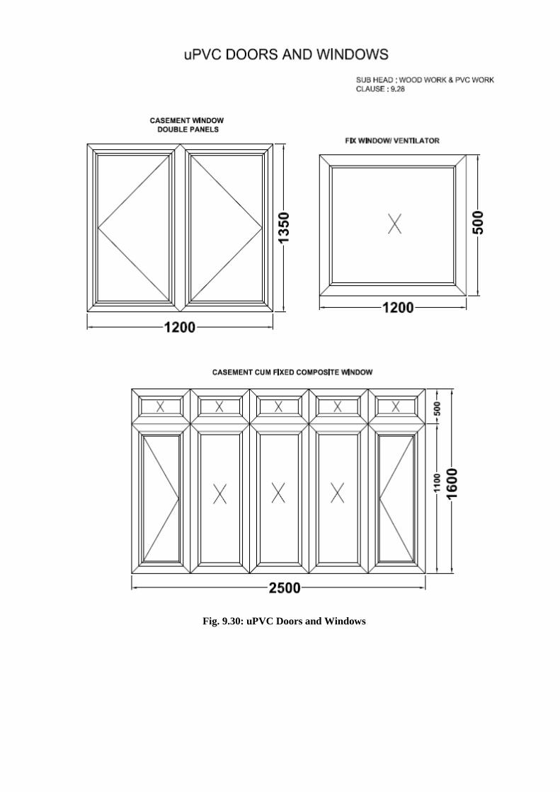
Fig. 9.30: uPVC Doors and Windows

Fig. 9.31: uPVC Doors and Windows

Fig. 9.32: uPVC Doors and Windows
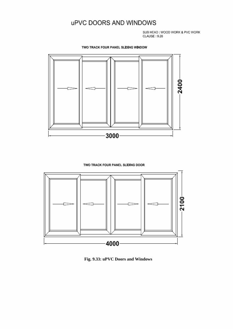
Fig. 9.33: uPVC Doors and Windows

Fig. 9.34: uPVC Doors and Windows

Fig. 9.35: uPVC Doors and Windows

Fig. 9.36: uPVC Doors and Windows (Typical casement system)

Fig. 9.37: uPVC Doors and Windows (Typical casement with top fixed system)
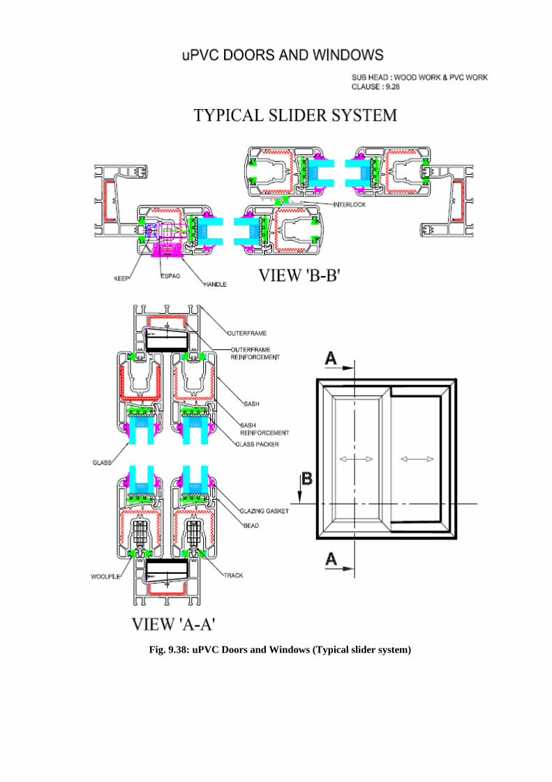
Fig. 9.38: uPVC Doors and Windows (Typical slider system)

Annexure ‘E’
22.19 UNDER DECK INSULATION SYSTEM (DSR ITEM 26.8)
(Figure 22.13)
22.19.1 Materials
50mm thick extruded polystyrene rigid insulation board of required size for Underdeck
Insulation System, complying with ISO 4898:2008 & ASTM C 578-08b-type VI, having thermal
conductivity of 0.0289 W/mk as per ASTM C 578 (Measured as per IS 3346), Compressive strength of
> 350 KPA listed as per ASTM D 1621, density of 34-36 kg/Cum as per ASTM D 1622, Water absorption
< 1% by Volume as per ASTM D 2842, Oxygen Index of 24.1 to 28.1 listed as per ASTM D 2863, cell size
0.4mm of dia (max) as per ASTM D 3576. Fire retardant property as per DIN , Part 1 of Class B2 and as
per ASTM E 84 Class A.
22.19.2 Installation Process
1. The specified Under Deck Insulation System shall be applied by an Authorized applicator only.
2. The level of the slab should be checked and kept within permissible limit of variation of 3 to
5mm.
3. The Substrate/Roof Underdeck on which the insulation system needs to be installed must be
free from all waste products such as petroleum, grease, oil, solvents, vegetable or mineral oil,
animal fat etc.
4. The Insulation board must be fixed to the concrete slab from inside with the help of water
based adhesive and Fasteners with PVC Capping. This has to be ensured that the PVC screws
are embedded in the concrete with a minimum distance of 50mm from the edges and have a
pull out strength of 0.3 kN.
22.19.3 Requirement for extruded polystyrene rigid insulation board
Since this product is a performance based product, the third Party testing is Mandatory and should be
done from any NABL approved laboratory or any other accreditation body which operates in
accordance with test ISO/IEC 17011 and accredits labs as per ISO/IEC-17025 for testing.
Sr. No Requirement Test Standard Remarks
1 Thermal Conductivity Having 180 days aged thermal conductivity of 0.0289 W/mk.
ASTM C 578 Mandatory
2 Compressive strength of > 350 KPA. ASTM D 1621 Mandatory
3 Density of 34-36 kg/Cum. ASTM D 1622 Mandatory
4 Water absorption < 1% by Volume. ASTM D 2842 Mandatory
5 Oxygen Index of 24.1 to 28.1 ASTM D 2863 Mandatory
6 Cell size 0.4mm of dia (max). ASTM D 3576 Mandatory
7 Fire retardant property as per DIN , Part 1 of Class B2
------ Mandatory
8 Fire retardant property ASTM E 84 CLASS A
Mandatory

22.19.4 Measurements
Length and breadth of the roofing insulation shall be measured correct to a cm and
the surface area worked out in square metre of the finished work.
No deduction shall be made for openings of areas upto 40 square decimetre. No extra
payment will be made for any extra material or labour involved in forming such openings. For
openings exceeding 40 square decimetre in area, deduction for the full opening will be made,
but no extra will be paid for any extra material or labour involved in forming such openings.
22.19.5 Rate
The rate shall include the cost of all materials and labour involved in all the operations
described above including scaffolding if any required.

Sub Head: New Technologies and Materials
Clause: 22.19
Pattern of Laying XPS Location of Fasteners
Fig. 22.13 Location of Fasteners of extruded Polystyrene Rigid Underdeck insulation.

22.20 CAVITY WALL INSULATION SYSTEM (DSR ITEM 26.7)
(Figure 22.14)
22.20.1 Materials
50mm thick extruded polystyrene rigid insulation board of required size between cavity wall,
complying with ISO 4898:2008 & ASTM C 578-08b-type VI, having thermal conductivity of 0.0289
W/mk as per ASTM C 578 (Measured as per IS 3346), Compressive strength of > 350 KPA listed as per
ASTM D 1621, density of 34-36 kg/Cum as per ASTM D 1622, Water absorption < 1% by Volume as
per ASTM D 2842, Oxygen Index of 24.1 to 28.1 listed as per ASTM D 2863, cell size 0.4mm of dia (
max) as per ASTM D 3576. Fire retardant property as per DIN 4102 Part 1 of class B2 and as per ASTM
E 84 Class A.
22.20.2 Installation Process
1. The Cavity Wall Insulation system has to be installed by the Trained and authorized Applicator Only.
2. The insulation board has to be installed from Inside of the wall and should be firmly struck with the help of water based adhesive applied on all the four sides of the Insulation Board.
3. The Struck insulation board should further be fixed with the help pf PVC fasteners, which has be fastened on all the four corners in such a way that it should hold adjoining insulation sheets as well.
22.20.3 Requirement for extruded polystyrene rigid insulation board
Since this product of performance based product, the third Party testing is Mandatory and
should be done from any NABL approved laboratory or from any NYLAP approved international
laboratory.
Sr. No Requirement Test Standard Remarks
1 Thermal Conductivity Having 180 days aged thermal conductivity of 0.0289 W/mk.
ASTM C 578 Mandatory
2 Compressive strength of > 350 KPA. ASTM D 1621 Mandatory
3 Density of 34-36 kg/Cum. ASTM D 1622 Mandatory
4 Water absorption < 1% by Volume. ASTM D 2842 Mandatory
5 Oxygen Index of 24.1 to 28.1 ASTM D 2863 Mandatory
6 Cell size 0.4mm of dia (max). ASTM D 3576 Mandatory
7 Fire retardant property as per DIN , Part 1 of Class B2
------ Mandatory
8 Fire retardant property. ASTM E 84 CLASS A
Mandatory
22.20.4 Measurements
Length and breadth of the wall insulation shall be measured correct to a cm and the
surface area worked out in square metre of the finished work.
22.20.5 Rate
The rate shall include the cost of all materials and labour involved in all the operations
described above including scaffolding if any required.

Sub Head: New Technologies and Materials
Clause: 22.20
Fig. 22.14 Cavity wall thermal insulation
system with Rigid foam insulation

Annexure ‘F’
22.21 Mineral Fibre Ceiling Tile (DSR ITEM 26.27.1 to 26.27.3)
(Figure 22.15 to 22.17)
22.21.1 16 mm Mineral Fibre ceiling Tile
22.21.1.1 Material
Ceiling tiles shall be of made of mineral fibre of dimension 595x595mm with 16 mm
thickness humidity resistance 99% Thermal conductivity K = 0.052-0.057 w/mK colour white,
fire performance UK Class 0/Class 1 (BS 476 pt -6&7) suitable for green building application
(GRIHA Criteria 17 & 29 SWAGRIHA 12) with recycled content not less than 30 % and light
reflectance not less than 85%. NRC of 0.55 to 0.6. The tile and grid should carry a limited
warranty of one year against sag.
22.21.1.2 Frame
The frame work shall consist of G.I. ' T ' Sections for Main runners 15x38x3000mm
length, Cross runners of 15x32x1200mm & 15x32x600mm size, 0.33 mm thickness as specified in
the item with galvanization of 120 gsm (minimum) and perimeter wall angle of 0.40mm
(minimum) thick gauge having equal flanges of size 24x24mm made from precoated G.I. Coil
length of 3.0m fixed to the wall with the help of plastic rawl plugs at 450mm centre to centre with
50mm long dry wall SS screws. The frame work shall be executed in a manner so as to form a grid
of 600x600mm as specified in the item.
22.21.1.3 Fixing of Ceiling Tiles
The frame work shall be suspended from ceiling by L shape level adjuster hangers made
of G.I. Of size 85x25x25x2mm having die cut slit for sliding into main T section, also having precut
hole so that 6mm fully threaded MS rod length upto 1000mm goes through it and pierces into M6
dash fasteners (Galvanising of 80 gsm minimum) of 6 mm dia 50mm long, fixed to the slab and
then tightened with check nuts, subsequently the bottom of 6 mm rod will be tightened with
check nuts for adjusting the line & level. The tile shall be laid on 15x32mm wide T section flanges
colour white having rotary stitching on all T sections i.e. the main runner, 1200 mm & 600 mm
cross Tees with a web height of 32 mm and load carrying capacity of 7.57Kgs/m2.
22.21.1.4 Measurements
Length and breadth of superficial area of the finished work shall be measured correct to a
centimetre. Area shall be calculated in square meter correct to two places of decimal. No
deduction will be made to openings of areas upto 40 square decimeter nor shall extra payment be
made either for any extra material or labour involved in forming such openings. For openings
exceeding 40 square decimetre in area, deduction in measurements shall be made but extra
payment will be made for any extra material or labour involved in making such openings.
22.21.1.5 Rate
The rate shall include the cost of all the materials and labor involved in all the operation
described above including scaffolding etc, if any required.

22.21.2 20mm Mineral Fibre Ceiling Tile
22.21.2.1 General specification for providing and fixing mineral fibre false ceiling tiles item to be
same as mentioned in para 22.21.1.1 to 22.21.1.5 except the thickness of mineral fibre tile will be
20 mm and NRC value 0.7.
22.21.3 16 mm Antimicrobial Ceiling Tile
22.21.3.1 General specification for providing and fixing 16 mm thick beveled tegular mineral
fibre false ceiling tiles item to be same as mentioned in para 22.21.1.1 to 22.21.1.5 except the tile
will be Anti-microbial false ceiling tiles.

Sub Head: New Technologies and
Materials
Clause: 22.21
Fig. 22.15: 16mm thick beveled tegular mineral fibre false ceiling tiles (NRC 0.55 to 0.6)

Sub Head: New Technologies and
Materials
Clause: 22.21
Fig. 22.16: 20mm thick beveled tegular mineral fibre false ceiling tiles (NRC 0.7)

Sub Head: New Technologies and
Materials
Clause: 22.21
Fig. 22.17: 16mm thick bevelled tegular mineral fibre Anti microbial false ceiling tiles
Annexure ‘G’
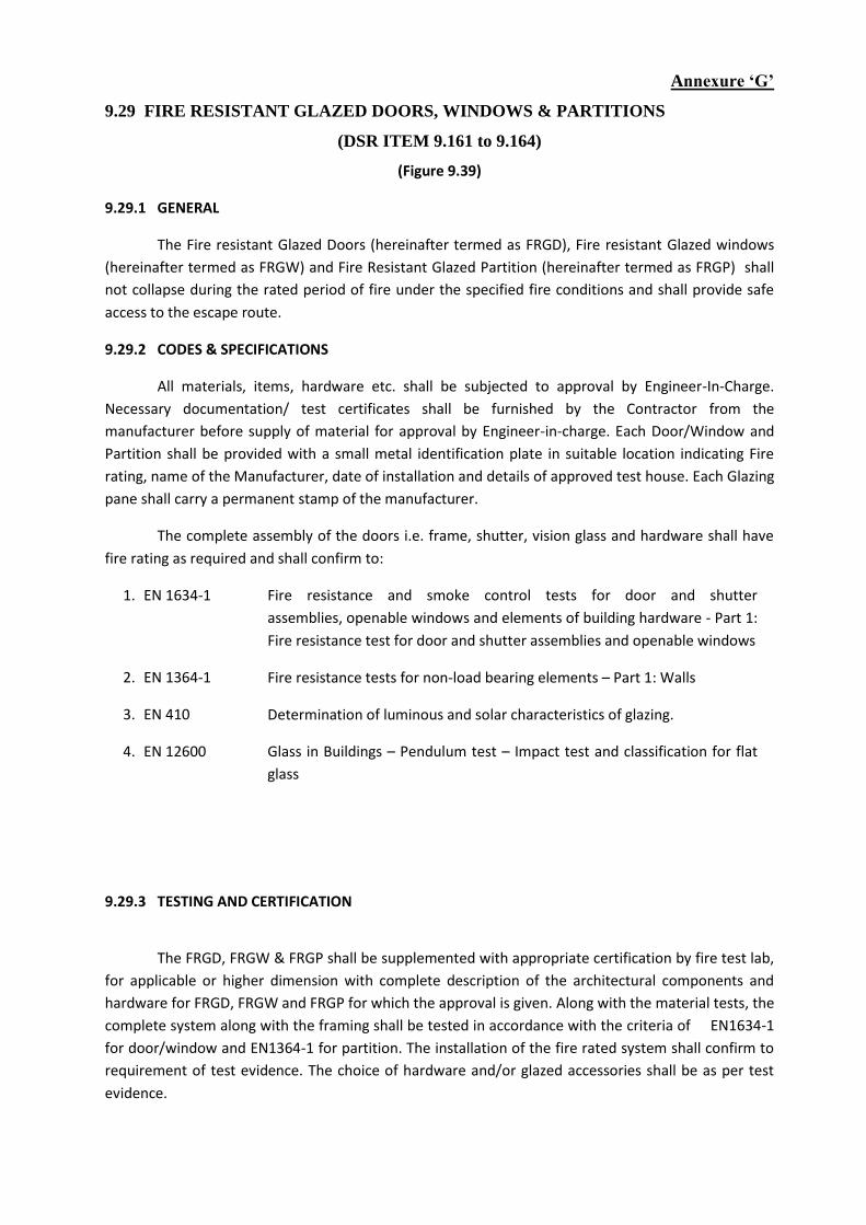
9.29 FIRE RESISTANT GLAZED DOORS, WINDOWS & PARTITIONS
(DSR ITEM 9.161 to 9.164)
(Figure 9.39)
9.29.1 GENERAL
The Fire resistant Glazed Doors (hereinafter termed as FRGD), Fire resistant Glazed windows
(hereinafter termed as FRGW) and Fire Resistant Glazed Partition (hereinafter termed as FRGP) shall
not collapse during the rated period of fire under the specified fire conditions and shall provide safe
access to the escape route.
9.29.2 CODES & SPECIFICATIONS
All materials, items, hardware etc. shall be subjected to approval by Engineer-In-Charge.
Necessary documentation/ test certificates shall be furnished by the Contractor from the
manufacturer before supply of material for approval by Engineer-in-charge. Each Door/Window and
Partition shall be provided with a small metal identification plate in suitable location indicating Fire
rating, name of the Manufacturer, date of installation and details of approved test house. Each Glazing
pane shall carry a permanent stamp of the manufacturer.
The complete assembly of the doors i.e. frame, shutter, vision glass and hardware shall have
fire rating as required and shall confirm to:
1. EN 1634-1 Fire resistance and smoke control tests for door and shutter
assemblies, openable windows and elements of building hardware - Part 1:
Fire resistance test for door and shutter assemblies and openable windows
2. EN 1364-1 Fire resistance tests for non-load bearing elements – Part 1: Walls
3. EN 410 Determination of luminous and solar characteristics of glazing.
4. EN 12600 Glass in Buildings – Pendulum test – Impact test and classification for flat
glass
9.29.3 TESTING AND CERTIFICATION
The FRGD, FRGW & FRGP shall be supplemented with appropriate certification by fire test lab,
for applicable or higher dimension with complete description of the architectural components and
hardware for FRGD, FRGW and FRGP for which the approval is given. Along with the material tests, the
complete system along with the framing shall be tested in accordance with the criteria of EN1634-1
for door/window and EN1364-1 for partition. The installation of the fire rated system shall confirm to
requirement of test evidence. The choice of hardware and/or glazed accessories shall be as per test
evidence.

9.29.4 Fire Resistant Doors/Windows and Partitions
9.29.4.1 Frame for Fire Resistant Glazed Door / Windows
Frame for Door/Window of 120 min fire rating shall be made of section 50 x 60 mm on
horizontal side & 35 x 60 mm on vertical sides having built in rebate made out of 1.6 mm thick GI sheet
(Zinc coating not less than 120gm/m²) suitable for mounting 120 min Fire Rated Glazed Door Shutters.
The frame shall be filled with Mineral wool Insulation having density min 96Kg/m³ . The frame will
have a provision of G.I. Anchor fastners 14 nos ( 5 each on vertical style & 4 on horizontal style of size
M10 x 80 ) suitable for fixing in the opening along with Factory made Template for SS Ball Bearing
Hinges of Size 100x89x3mm for fixing of fire rated glazed shutter . The frame shall be finished with a
approved fire resistant primer or Powder coating of not less than 30 micron in desired shade as per the
directions of Engineer - in- charge . (Cost of SS ball bearing hinges is excluded).
9.29.4.2 Frame for Fire Resistant Glazed Partitions
Frame for non load bearing fixed fire resistant glazed Partition for 120 min Fire Rating shall be
made out to a profile of dimension 60mm x 70 mm of 1.6 mm thick galvanised steel sheet as per test
evidence suitable for fixing fire rated glass for 120 min of both integrity & radiation control (EW120) &
minimum 15 min of insulation (EI15).The profile has to be fixed to the supporting construction by
means of anchor fasteners of size M10 x 80, every 150 mm from the edges and every 500 mm (approx)
c/c. The frame shall be filled with mineral wool insulation of density min 96kg/m³. and finished with a
approved fire resistant primer or Powder coating of not less than 30 micron in desired shade as per
the directions of Engineer - in- charge .
9.29.4.3 Shutter for Fire Resistant Doors/Windows Glazed fire resistant door shutters 60 mm thick of 120 min Fire Rating shall be confirming to
IS:3614 (Part II) or EN1634-1:1999, tested and certified as per laboratory approved by Engineer-in-
charge, with suitable mounting on door frame, consisting of vertical styles, top rail & side rail 60 mm
x 60 mm wide and bottom rail of 110 mm x 60 mm made out of 1.6mm thick G.I. sheet (zinc coating
not less than 120gm/m²) duly filled mineral wool insulation having density min 96 kg/m³ and fixing
with necessary stainless steel ball bearing hinges of size 100x89x3mm of approved make, including
applying a coat of approved fire resistant primer or powder coating not less than 30 micron etc all
complete as per direction of Engineer-in-charge (panelling to be paid for separately).
9.29.4.4 Fire Resistant Glass for Doors/Windows and Partitions
Glazing to be fixed in fire resistant doors/window shutters and fixed Partitions with G.I.
beading made out of 1.6 mm thick G.I. sheet (zinc coating not less than 120 gm/m²) of size 20 x 33 mm
screwed with M4 x 38 mm SS screws at distance 75 mm from the edges and 150 mm c/c , including
applying a coat of approved fire resistant primer/powder coating of not less than 30 micron on G.I.
beading, & special ceramic tape of 5 x 20 mm size etc complete in all respect as per direction of
Engineer-in-charge. The glass should be clear, toughened, interlayered, non-wired fire resistant having
11 mm minimum thickness of approved brand with 120 minutes of fire resistance both integrity &
radiation control (EW120) and minimum 15 min of insulation (EI15) and having a sound reduction of
more than 35dB and LT of 85%. Glass shall be compliant to class 2B2/1B1 category of Impact
Resistance as per EN 12600. The glass should be manufactured in UL & TUV audited Facility and
including UL-EU Certification. The maximum glazing size cannot be more than 1100 mm x 2200 mm
(w x h) or 2.42 sq mts in total area. The test report for the complete system (Glazed Door or Partition)
will be considered valid only if it contains the stamp and signature of the authorized signatory from the
glass manufacturer. (Actual glass size is to be measured at site for payments).
The complete assembly shall satisfy the given criteria of fire resistance - stability, fire integrity,
radiation control and insulation as per above mentioned rating required.
9.29.5 Vision Panel For FRD 9.29.5.1 Vision Panel for Fire Door
Specifications for glass for Vision panels for Fire Rated Door shall be as per para C above.
Minimum size of glass to be used for vision panels shall not be less than 350 mm x 350 mm.
9.29.6 DELIVERABLES BY THE CONTRACTOR Following documentation/ drawings shall be furnished along with the Doors/window/partition.
1) Prototype Test Certificate by national/international test house 2) Shop drawings 3) Specification/ Manufacturer’s literature, Test certificates and other documentation for materials
and items intended to be used. 4) Certificate indicating that design and installation of Doors and hardware conforms to
norm laid down by approved national/international test house. 5) Test report to be attested by Fire rated glass manufacturer. 6) The Fire rated glass applicator has to be approved by Fire rated Glass Manufacturer has to
Submit the approved applicator certificate.
9.29.7 Measurements
9.29.7.1 Measurement of frame for door/window/partition
The outer length of the vertical and horizontal members of fire rated door/window frame shall
be measured in running metres including embedded length in floor upto two decimal places.
The outer length of the vertical and horizontal members of fire rated partition frame shall be
measured in running metres upto two decimal places.
9.29.7.2 Measurement of shutter for door/window
Length and width of the shutters shall be measured to the nearest cm in closed position
covering the rebates of the frames but excluding the gap between the shutter and the frame. Area is
calculated to the nearest 0.01 sqm.
9.29.8 Rate
The rate of frame includes the cost of the materials and labour involved in all the operations.
The cost of SS ball bearing hinges and any other hardware which may be required, shall be paid for
separately.
The specified rate for door/window shutter include the cost of the door/window shutter and
labour involved in fixing of the shutter. Fittings, fixtures and paneling on the door shutter except
hinges & screws shall be paid extra as provided.
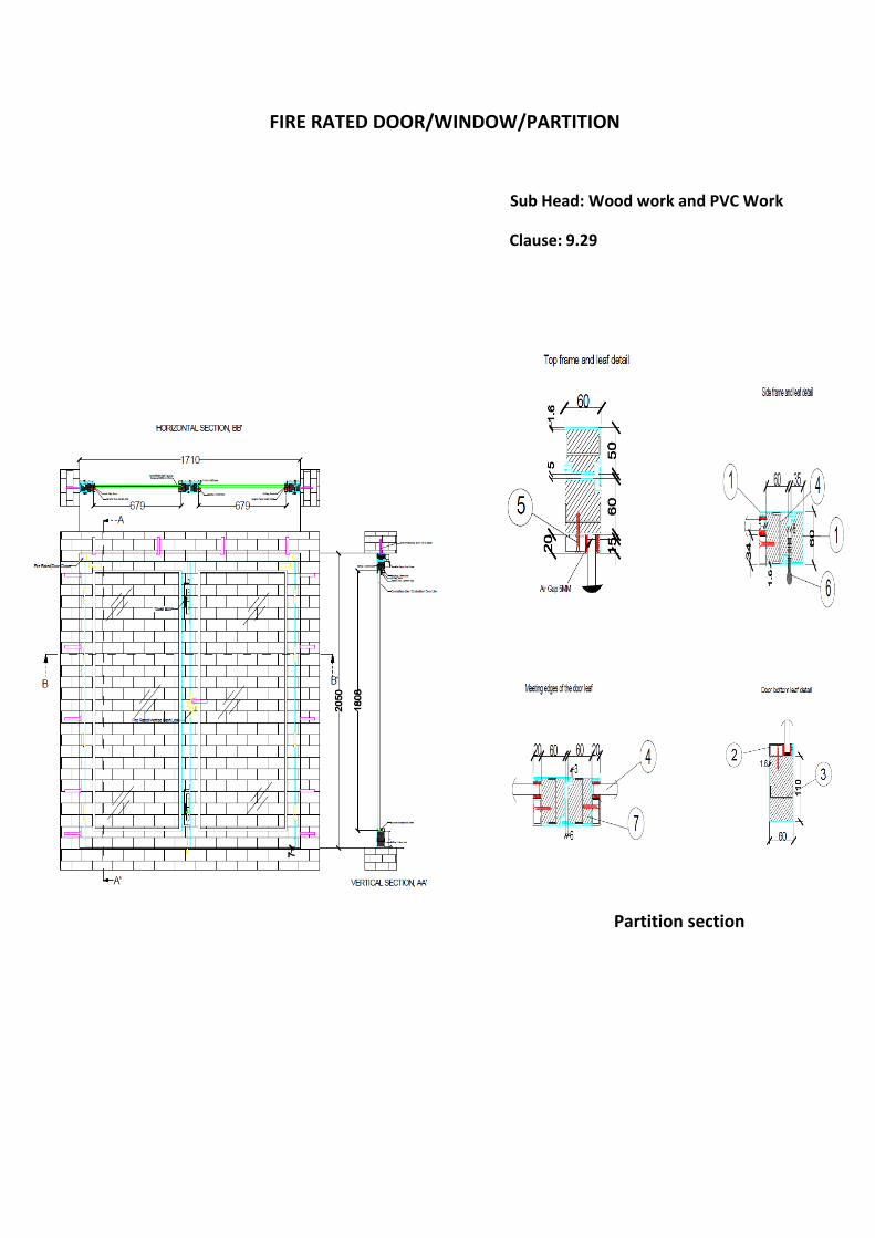
FIRE RATED DOOR/WINDOW/PARTITION
Sub Head: Wood work and PVC Work
Clause: 9.29
Partition section

Glass
Sl.
No
Type Glass Thickness Size Quantity
1 Double
leaf door
Clear toughened
interlayer fire rated
glass
11 mm 679mmx1808mm 2
1. Door frames and leaf: 1.6 mm thick GI sheet. 2. Glazing bead: 1.6 mm thick GI sheet. 3. Stiffeners: 1.6 mm thick GI sheet. 4. Glass: Clear toughened interlayer fire rated glass. 5. Beading screw: M4x35 mm @ 150mm (approx) C/C. 6. SS ball bearing butt hinges 100x89x3 mm. Ceramic wool infill (Density – 96 kg/m3)
Fig. 9.39 Detail of Fire rated Door/Window/Partition
Annexure ‘H’
22.22 LIGHT WEIGHT CALCIUM SILICATE FALSE CEILING TILES
(DSR ITEM 26.22 & 26.23)
(Figure 22.18)
22.22.1 15mm Tegular edged light weight calcium silicate false ceiling tiles
22.22.1.1 Material
15 mm thick tegular edged light weight calcium silicate false ceiling tiles with integral densified calcium silicate reinforced with fibre and natural filler false ceiling tiles of Size 595x595 mm of approved texture, design and patterns having NRC (Noise Reduction coefficient) of 0.50 (minimum) as per IS 8225:1987, Light reflectance of 85% (minimum). Non combustible as per BS: 476 (part-4), fire performance as per BS:476 (part 6 &7), humidity resistance of 100%, thermal conductivity <0.043 W/mK as per ASTM 518:1991.The tests shall have average density of 370 kg/m3 (minimum) as per ECBC code 2007. The tile shall be primer coated on both sides and the fair surface shall be having a factory finish in two coats of white dispersion type solvent free paint.
22.22.1.2 Frame
The frame work shall consist of G.I. ' T ' Sections for Main runners 24x38x3000mm length, Cross runners of 24x32x1200mm & 24x32x600mm size, 0.33 mm thickness as specified in the item with galvanisation of 120 gsm (minimum) and perimeter wall angle of 0.40mm (minimum) thick gauge having equal flanges of size 24x24mm made from precoated G.I. Coil length of 3.0m fixed to the wall with the help of plastic rawl plugs at 450mm centre to centre with 40mm long dry wall SS screws. The frame work shall be executed in a manner so as to form a grid of 600x600mm as specified in the item.
22.22.1.3 Fixing of Ceiling Tiles
The frame work shall be suspended from ceiling by L shape level adjuster hangers made of G.I. Of size 85x25x25x2mm having die cut slit for sliding into main T section, also having precut hole so that 6mm fully threaded MS rod length upto 1000mm goes through it and pierces into M6 dash fasteners (Galvanising of 80 gsm minimum) of 6 mm dia 50mm long, fixed to the slab and then tightened with check nuts, subsequently the bottom of 6 mm rod will be tightened with check nuts for adjusting the line & level. The tile shall be laid on 24x32mm wide T section flanges colour white having rotary stitching on all T sections i.e. the main runner, 1200 mm & 600 mm cross Tees with a web height of 32 mm and load carrying capacity of 7.57Kgs/m2.
22.22.1.4 Measurements
Length and breadth of superficial area of the finished work shall be measured correct to a
centimetre. Area shall be calculated in square meter correct to two places of decimal. No deduction
will be made to openings of areas upto 40 square decimeter nor shall extra payment be made either
for any extra material or labour involved in forming such openings. For openings exceeding 40 square
decimetre in area, deduction in measurements shall be made but extra payment will be made for any
extra material or labour involved in making such openings.
22.22.1.5 Rates
The rate shall include the cost of all the materials and labor involved in all the operation
described above including scaffolding etc, if any required.

22.22.2 15mm thick integral densified micro edged light weight calcium silicate false ceiling tiles
22.22.2.1 Material
15mm thick integral densified micro edged light weight calcium silicate false ceiling tiles with integral densified calcium silicate reinforced with fibre and natural filler false ceiling tiles of Size 595x595 mm of approved texture, design and patterns having NRC (Noise Reduction coefficient) of 0.50 (minimum) as per IS 8225:1987, Light reflectance of 85% (minimum). Non combustible as per BS: 476 (part-4), fire performance as per BS:476 (part 6 &7), humidity resistance of 100%, thermal conductivity <0.043 W/mK as per ASTM 518:1991.The tests shall have average density of 370 kg/m3 (minimum) as per ECBC code 2007. The tile shall be primer coated on both sides and the fair surface shall be having a factory finish in two coats of white dispersion type solvent free paint.
22.22.2.2 Frame
The frame work shall consist of G.I. ' T ' Sections of 25 micron hot dipped galvanised iron section of 0.40mm thick on Silhouette profile, rotary stitched double webbed white with 6mm reveal profile (white/black) compromising of Main runners 15x42x3000mm length, Cross runners of 15x42x1200mm & 15x42x600mm size to form grid module of size 600x600mm. Galvanised iron perimeter wall angle of size 22x19x0.4mm of length 3000mm to be fixed on periphery wall/partition with the help of plastic rawl plugs at 450mm C/C and 40mm long dry wall SS screws. The work shall be carried out as per specifications, drawing and as per direction of Engineer-in-Charge.
22.22.2.3 Fixing of Ceiling Tiles
The frame work shall be suspended from ceiling by L shape level adjuster hangers made of G.I. Of size 85x25x25x2mm having die cut slit for sliding into main T section, also having precut hole so that 6mm fully threaded MS rod length upto 1000mm goes through it and pierces into M6 dash fasteners (Galvanising of 80 gsm minimum) of 6 mm dia 50mm long, fixed to the slab and then tightened with check nuts, subsequently the bottom of 6 mm rod will be tightened with check nuts for adjusting the line & level. The tile shall be laid on 15x42mm wide T section flanges colour white having rotary stitching on all T sections i.e. the main runner, 1200mm & 600mm cross Tees with a web height of 42 mm and load carrying capacity of 7.57Kgs/m2.
22.22.2.4 Measurements
Same as the item no 22.22.1.4. 22.22.2.5 Rates
Same as the item no 22.22.1.5.

Sub Head: New Technologies and
Materials
Clause: 22.22
Fig. 22.18: 15mm Tegular/integral densified micro edged Light weight calcium silicate false ceiling
tiles