and Technology Journal Original Photo-induced light: future
15
Available online at www.sciencedirect.com Journal of Applied Research and Technology www.jart.ccadet.unam.mx Journal of Applied Research and Technology 15 (2017) 609–623 Original Photo-induced ignition phenomenon of carbon nanotubes by Xenon pulsed light: Ignition tests analysis, automotive and new potential applications, future developments Patrizio Primiceri, Roberto de Fazio, Luciano Strafella, Antonio Paolo Carlucci, Paolo Visconti ∗ Department of Innovation Engineering, University of Salento, 73100 Lecce, Italy Received 1 March 2017; accepted 3 August 2017 Available online 15 December 2017 Abstract The possibility to use carbon nanotubes (CNTs) enriched with a certain amount of metal nanoparticles for photo-inducing the combustion of liquid fuel sprays, gaseous and solid fuels was investigated in different research works. CNTs photo-ignition phenomenon has been used to trigger the combustion of different fuel typologies, demonstrating better features compared with those obtained by employing a traditional spark-plug. These improvements are due to the presence of distributed ignition nuclei inside the combustion chamber, so obtaining better values of the peak pressure, ignition delay and combustion duration. In this work, the CNTs photo-ignition phenomenon has been analyzed in order to find the minimum energy values needed to trigger the ignition, by varying the light pulse parameters and the nanoparticles concentration, Multi Wall CNTs (MWCNTs) – ferrocene, by weight. Afterwards, the results of combustion processes, triggered by using the nanoparticles, are shown comparing them with those obtained by means the spark plug and with results already published related to other fuel typologies. Hence, an overview of the possible applications of this photo-ignition phenomenon, beside that of the automotive field, is presented, also considering the disadvantages of the Xe-lamp based triggering system. Therefore, after a critical discussion on the light source typology until now used (Xenon lamp), by reporting the possible contraindications deriving from the use of this light source in most of the applicative fields, a solution is here proposed. It involves the substitution of the Xe lamp with LED sources, showing also the related experimental setup. This solution is also strengthened by the our experimental observations of CNTs photo-ignition by using high-power white LEDs as light source, never reported up to now in the literature, and by better characteristics of adaptability, robustness, easy driving and benefits provided by the LEDs rather than the Xenon lamp. © 2017 Universidad Nacional Autónoma de México, Centro de Ciencias Aplicadas y Desarrollo Tecnológico. This is an open access article under the CC BY-NC-ND license (http://creativecommons.org/licenses/by-nc-nd/4.0/). Keywords: CNTs photo-ignition; Fuel combustion; Triggering system; Driving boards; Application fields; LED-based experimental setup 1. Introduction The CNTs photo-ignition was discovered accidentally by exposing a sample of Single Wall (SW) CNTs, with added 50% by weight of metal impurities, to the flash of an ordinary camera. Since then, several studies have been carried out for better clari- fying the photo-ignition process, characterizing the phenomenon in terms of needed luminous energy levels, by varying the con- centration by weight between CNTs and metal nanoparticles, the ∗ Corresponding author. E-mail address: [email protected] (P. Visconti). Peer Review under the responsibility of Universidad Nacional Autónoma de México. spectral range of the used light source (Xenon lamp) and other parameters involved in the photo-ignition process such as, for example, light pulse duration. Beside these characterizations, studies on the possible application fields in which the CNTs photo-ignition can be employed were carried out giving as result a wide variety of applications, from automotive, to aero-spatial rockets and energetic materials. Relatively to the automotive field, the internal combustion engine, one of the more promis- ing engine typologies, arouses particular interest in the scientific community. Hence, innovative solutions for combining high per- formance, in terms of engine power and fuel consumption and at the same time, low pollutants emissions, are the subject of numerous research studies. An example of this motor typology is the Homogeneous Charge Compression Ignition (HCCI) engine, https://doi.org/10.1016/j.jart.2017.08.001 1665-6423/© 2017 Universidad Nacional Autónoma de México, Centro de Ciencias Aplicadas y Desarrollo Tecnológico. This is an open access article under the CC BY-NC-ND license (http://creativecommons.org/licenses/by-nc-nd/4.0/).
Transcript of and Technology Journal Original Photo-induced light: future
A
ltTpm(tpttteb©t
K
1
ebSfic
M
1C
Available online at www.sciencedirect.com
Journal of Applied Researchand Technology
www.jart.ccadet.unam.mxJournal of Applied Research and Technology 15 (2017) 609–623
Original
Photo-induced ignition phenomenon of carbon nanotubes by Xenon pulsedlight: Ignition tests analysis, automotive and new potential applications,
future developmentsPatrizio Primiceri, Roberto de Fazio, Luciano Strafella, Antonio Paolo Carlucci, Paolo Visconti ∗
Department of Innovation Engineering, University of Salento, 73100 Lecce, Italy
Received 1 March 2017; accepted 3 August 2017Available online 15 December 2017
bstract
The possibility to use carbon nanotubes (CNTs) enriched with a certain amount of metal nanoparticles for photo-inducing the combustion ofiquid fuel sprays, gaseous and solid fuels was investigated in different research works. CNTs photo-ignition phenomenon has been used to triggerhe combustion of different fuel typologies, demonstrating better features compared with those obtained by employing a traditional spark-plug.hese improvements are due to the presence of distributed ignition nuclei inside the combustion chamber, so obtaining better values of the peakressure, ignition delay and combustion duration. In this work, the CNTs photo-ignition phenomenon has been analyzed in order to find theinimum energy values needed to trigger the ignition, by varying the light pulse parameters and the nanoparticles concentration, Multi Wall CNTs
MWCNTs) – ferrocene, by weight. Afterwards, the results of combustion processes, triggered by using the nanoparticles, are shown comparinghem with those obtained by means the spark plug and with results already published related to other fuel typologies. Hence, an overview of theossible applications of this photo-ignition phenomenon, beside that of the automotive field, is presented, also considering the disadvantages ofhe Xe-lamp based triggering system. Therefore, after a critical discussion on the light source typology until now used (Xenon lamp), by reportinghe possible contraindications deriving from the use of this light source in most of the applicative fields, a solution is here proposed. It involveshe substitution of the Xe lamp with LED sources, showing also the related experimental setup. This solution is also strengthened by the ourxperimental observations of CNTs photo-ignition by using high-power white LEDs as light source, never reported up to now in the literature, and
y better characteristics of adaptability, robustness, easy driving and benefits provided by the LEDs rather than the Xenon lamp.2017 Universidad Nacional Autónoma de México, Centro de Ciencias Aplicadas y Desarrollo Tecnológico. This is an open access article underhe CC BY-NC-ND license (http://creativecommons.org/licenses/by-nc-nd/4.0/).
eywords: CNTs photo-ignition; Fuel combustion; Triggering system; Driving boards; Application fields; LED-based experimental setup
spesparfii
. Introduction
The CNTs photo-ignition was discovered accidentally byxposing a sample of Single Wall (SW) CNTs, with added 50%y weight of metal impurities, to the flash of an ordinary camera.ince then, several studies have been carried out for better clari-ying the photo-ignition process, characterizing the phenomenonn terms of needed luminous energy levels, by varying the con-entration by weight between CNTs and metal nanoparticles, the
∗ Corresponding author.E-mail address: [email protected] (P. Visconti).Peer Review under the responsibility of Universidad Nacional Autónoma de
éxico.
cfant
https://doi.org/10.1016/j.jart.2017.08.001665-6423/© 2017 Universidad Nacional Autónoma de México, Centro de CienciasC BY-NC-ND license (http://creativecommons.org/licenses/by-nc-nd/4.0/).
pectral range of the used light source (Xenon lamp) and otherarameters involved in the photo-ignition process such as, forxample, light pulse duration. Beside these characterizations,tudies on the possible application fields in which the CNTshoto-ignition can be employed were carried out giving as result
wide variety of applications, from automotive, to aero-spatialockets and energetic materials. Relatively to the automotiveeld, the internal combustion engine, one of the more promis-
ng engine typologies, arouses particular interest in the scientificommunity. Hence, innovative solutions for combining high per-ormance, in terms of engine power and fuel consumption and
t the same time, low pollutants emissions, are the subject ofumerous research studies. An example of this motor typology ishe Homogeneous Charge Compression Ignition (HCCI) engine,Aplicadas y Desarrollo Tecnológico. This is an open access article under the

6 esear
aCTtno
ccpcIctttbip&
aiawnttt
eecspbitfontbaoiihtsccl
uya
ttHpsp
2
Mmetati∼toTsipsrst
2p
etaoot(bs((lef
at(Tt
10 P. Primiceri et al. / Journal of Applied R
lso indicated with CAI (Controlled Auto-Ignition) (Carlucci,iccarella, & Strafella, 2016; Chehroudi, 2012a; Zhao, 2007).he HCCI engine offers significant improvements relatively to
he fuel consumption and a drastic reductions of emissions ofitrogen oxides (NOx) and soot, combining the best propertiesf gasoline and diesel engines (Johansson, 2007).
However, in the HCCI engines, the control of combustion pro-ess presents some difficult related to the instant in which theombustion process starts; in fact, it depends on the temperature,ressure level and on the air-fuel mixture inside the combustionhamber (Carlucci, Laforgia, Motz, Saracino, & Wenzel, 2014).n order to overcome these issues, an innovative solution con-erns the use of nanoparticles for triggering the ignition and thushe combustion with a precise temporal control on the combus-ion process. Moreover, by using the nanoparticles, it is possibleo obtain a distributed and controlled ignition inside the com-ustion chamber; on the contrary, if the spark plug is used thegnition is triggered in a single point with consequent flame frontropagation (Carlucci & Strafella, 2015; Chehroudi, Vaghjiani,
Ketsdever, 2009).In this research work, the CNTs photo-ignition process was
nalyzed; by using a Xenon lamp, varying the emitted luminousntensity value and the light pulse duration by means of suit-ble Xenon lamp driving boards, the minimum ignition energiesere obtained for different concentration by weight of the usedanoparticles (i.e. MWCNTs and ferrocene). Furthermore, a par-icular phenomenon was investigated regarding the decrease ofhe ignition thresholds by applying two consecutive flashes tohe same sample.
Afterwards, the nanoparticles were used, in a proper realizedxperimental setup, for triggering the combustion of differ-nt gaseous fuels, CH4, LPG and H2, comparing the resultingombustion processes with those obtained using a traditionalpark-plug. The results show that the combustion processesresent higher peak pressure, lower ignition delay and com-ustion duration respect to those triggered by spark. In addition,t was verified that the achieved results are in agreement withhose already present in literature; in fact, by comparing the dif-erent parameters of the combustion processes with those ofther research works, it is possible to notice that the use ofanoparticles improves the combustion features regardless ofhe used fuel typology. After the analysis of results achievedy employing CNTs inside the combustion chamber as ignitiongents for triggering the gaseous fuel combustion, an overviewn the possible applications of the photo-ignition phenomenons presented. Many application fields were investigated and stud-es/works of different research groups are reported for clarifyingow the nanoparticles can be employed for the specific applica-ion and what may be the possible future applications. Finally, weuggest a further innovative application related to the periodiclean, by using the CNTs photo-ignition, of vehicles catalyticonverters; in fact, on this topic, there are numerous studies initerature.
For concluding, we present the disadvantages related to these of a Xenon lamp in this type of applications. After the anal-sis of the technical limitations of the Xe lamp, we proposen innovative solution based on the use of another light source
ttis
ch and Technology 15 (2017) 609–623
ypology, i.e. LEDs source, being huge the developments andechnological advances related to the production of such devices.ence, an experimental apparatus which employs LEDs cou-led with optical fibers, in place of the Xe lamp, is proposed,howing also the first experimental results concerning the CNTshoto-ignition by using LED devices as light source.
. Materials and methods
In this paragraph, it is reported a characterization of theWCNT/ferrocene ignition process, in terms of the requiredinimum ignition energy (MIE) of Xe light pulse, for differ-
nt concentrations by weight of the mixture itself; subsequently,he mixture behavior when subjected to two light pulses, onefter the other, will be discussed. The carried out experimentalests (experimental setup shown in Fig. 1b) concerned the photo-nduced ignition of MWCNTs/ferrocene mixtures (an amount of
6.5 mg) by varying mixture’s weight ratio and Xe light pulseime duration and luminous intensity applied on the sample, inrder to find the energy threshold value for each weight ratio.he luminous energy emitted by the 50J Xe flash lamp was mea-ured by using the light energy meter (model PM100D, shownn Fig. 1a) and the pyroelectric sensor (model ES145C), bothrovided by Thorlabs, with a distance lamp-sensor of 4 mm (ashown in Fig. 1c); then, each time, the pyroelectric sensor waseplaced with the MWCNTs/ferrocene mixture (Fig. 1d) pre-erving the same distance lamp-sample to perform the ignitionest.
.1. Photo-ignition tests of CNTs/ferrocene mixtures by Xeulsed light
The photo-ignition tests were performed making use of prop-rly realized driving boards; in particular of the driving boardhat employs an IGBT switch for adjusting the pulse time lengths function of the signal applied to the IGBT gate and afterwardsf the ac-powered driving board characterized by the absencef a storage capacitor. This last, by acting on a potentiome-er, allows to regulate the luminous energy emitted by the lampVisconti et al., 2016). In the first tests campaign the drivingoard with the IGBT was employed; it was triggered by a pulsedignal coming from a PC and was provided of a potentiometerRPOT) used to adjust the desired time duration of the light pulsePrimiceri, Visconti, Longo, Tramis, & Carlucci, 2016). Theuminous energy was determined as average of four measurednergy values, each flash repeated after 10 s (to give enough timeor fully recharging of storage capacitor).
From measured energy values, captured by the whole sensorrea (15.9 cm2), able to ignite the MWCNT/ferrocene mix-ures with different weight ratio, the luminous energy densitymJ/cm2) was calculated. As result of photo-ignition tests,able 1 reports the obtained minimum ignition energy (MIE) and
he relative standard deviation, together with the RPOT poten-
iometer value and the related pulse time length. The ignitionests started with a pulse energy well below that required forgnition and then it was progressively increased with smallteps (arising the potentiometer value of 0.5 k� each time) until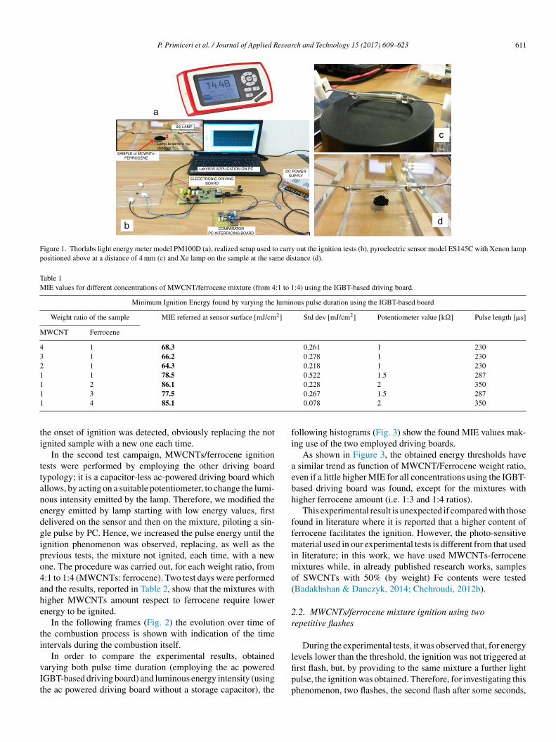
P. Primiceri et al. / Journal of Applied Research and Technology 15 (2017) 609–623 611
a50j LAMP
SAMPLE of MCWNTs-FERROCENE
Lamp to sampledistance
LabVIEW APPLICATION ON PC
ELECCTRONIC DRIVINGBOARD
b COMPARATORPC-INTERFACING BOARD
DC POWERSUPPLY
c
d
Figure 1. Thorlabs light energy meter model PM100D (a), realized setup used to carry out the ignition tests (b), pyroelectric sensor model ES145C with Xenon lamppositioned above at a distance of 4 mm (c) and Xe lamp on the sample at the same distance (d).
Table 1MIE values for different concentrations of MWCNT/ferrocene mixture (from 4:1 to 1:4) using the IGBT-based driving board.
Minimum Ignition Energy found by varying the luminous pulse duration using the IGBT-based board
Weight ratio of the sample MIE referred at sensor surface [mJ/cm2] Std dev [mJ/cm2] Potentiometer value [k�] Pulse length [�s]
MWCNT Ferrocene
4 1 68.3 0.261 1 2303 1 66.2 0.278 1 2302 1 64.3 0.218 1 2301 1 78.5 0.522 1.5 2871 2 86.1 0.228 2 35011
ti
ttanedgipo4ahe
ti
vIt
fi
aebh
ffmimo(
2r
3 77.5
4 85.1
he onset of ignition was detected, obviously replacing the notgnited sample with a new one each time.
In the second test campaign, MWCNTs/ferrocene ignitionests were performed by employing the other driving boardypology; it is a capacitor-less ac-powered driving board whichllows, by acting on a suitable potentiometer, to change the lumi-ous intensity emitted by the lamp. Therefore, we modified thenergy emitted by lamp starting with low energy values, firstelivered on the sensor and then on the mixture, piloting a sin-le pulse by PC. Hence, we increased the pulse energy until thegnition phenomenon was observed, replacing, as well as therevious tests, the mixture not ignited, each time, with a newne. The procedure was carried out, for each weight ratio, from:1 to 1:4 (MWCNTs: ferrocene). Two test days were performednd the results, reported in Table 2, show that the mixtures withigher MWCNTs amount respect to ferrocene require lowernergy to be ignited.
In the following frames (Fig. 2) the evolution over time ofhe combustion process is shown with indication of the timentervals during the combustion itself.
In order to compare the experimental results, obtainedarying both pulse time duration (employing the ac poweredGBT-based driving board) and luminous energy intensity (usinghe ac powered driving board without a storage capacitor), the
lfipp
0.267 1.5 2870.078 2 350
ollowing histograms (Fig. 3) show the found MIE values mak-ng use of the two employed driving boards.
As shown in Figure 3, the obtained energy thresholds have similar trend as function of MWCNT/Ferrocene weight ratio,ven if a little higher MIE for all concentrations using the IGBT-ased driving board was found, except for the mixtures withigher ferrocene amount (i.e. 1:3 and 1:4 ratios).
This experimental result is unexpected if compared with thoseound in literature where it is reported that a higher content oferrocene facilitates the ignition. However, the photo-sensitiveaterial used in our experimental tests is different from that used
n literature; in this work, we have used MWCNTs-ferroceneixtures while, in already published research works, samples
f SWCNTs with 50% (by weight) Fe contents were testedBadakhshan & Danczyk, 2014; Chehroudi, 2012b).
.2. MWCNTs/ferrocene mixture ignition using twoepetitive flashes
During the experimental tests, it was observed that, for energy
evels lower than the threshold, the ignition was not triggered atrst flash, but, by providing to the same mixture a further lightulse, the ignition was obtained. Therefore, for investigating thishenomenon, two flashes, the second flash after some seconds,
612 P. Primiceri et al. / Journal of Applied Research and Technology 15 (2017) 609–623
Table 2Minimum ignition energy [mJ/cm2] required to ignite each concentration of the mixture from 4:1 to 1:4. The mean value is obtained from the first and second testcampaign.
Minimum Ignition Energy found by varying the luminous pulse intensity by means of the capacitor-less ac-powered driving board
Weight ratio of the sample First test Second tests Mean value [mJ/cm2]
MWCNT Ferrocene Energy density[mJ/cm2]
Std dev Potentiometer value Energy density[mJ/cm2]
Std dev Potentiometer value
4 1 47.58 0.613 8 k� 55.15 0.827 7.5 k� 51.373 1 55.3 0.770 7.5 k� 62.2 1.283 7 k� 58.752 1 46.81 1.129 8 k� 62.45 0.603 7 k� 54.631 1 59.88 0.741 7 k� 69.78 0.759 6.5 k� 64.831 2 61.08 1.008 7 k� 78.4 1.105 6 k� 69.741 3 85.83 0.780 5 k� 91.60 1.530 5 k� 88.721 4 79.68 1.513 5.5 k� 96.25 0.940 4.5 k� 87.97
0 sec 0.03 sec 0.1 sec
0.46 sec0.32 sec0.22 sec0.16 sec
0.59 sec 0.72 sec 0.85 sec 1 sec
Figure 2. Frames of combustion process taken during ignition phenomenon.
95
90
85
80
75
70
65
60
55
50
45
404:1 3:1 2:1 1:1 1:2 1:3 1:4
MWCNT : ferrocene weight ratio
Ene
rgy
dens
ity [m
j/cm
2]
capacitor-lessdriving board
IGBT-baseddriving board
Figure 3. Comparison between the MIE found with the capacitor-less and the IGBT-based board.

P. Primiceri et al. / Journal of Applied Research and Technology 15 (2017) 609–623 613
Table 3Comparison of the mixture’s ignition using 1:3 and 2:1 MWCNTs:ferrocene weight ratio; 2:1 mixture needs lowerlight energy to be ignited.
wudtlpwm
itoflocNmom
lcrip(cjlctbet∼pnFs2aeTtf
stImNaetticFw
swma
3
NcaransBDpalmme(
3c
ere applied on the same mixture (2:1 and 1:3 were the mixturessed as sample for this test). Table 3 shows the flash time durationepending on the resistance value RPOT and thus the energy ofhe incident light on the mixtures. Starting with energy levelsower than the threshold (corresponding to 1 k� value of theotentiometer RPOT), no mixture was ignited at first flash pulse,hile at second flash the ignition was observed only for the 2:1ixture, as reported in blue in Table 3.For the potentiometer value of 1.5 k�, 2:1 mixture was
gnited at first flash (red circle), while for the 1:3 one the igni-ion was obtained only at second flash. With potentiometer valuef 2 k�, the ignition was triggered for all the mixtures at firstash pulse. The following Figure 4 shows the frame sequencef the ignition test with potentiometer value equal to 1.5 k�; itan be noticed that the ignition occurs only for the 2:1 (MWC-Ts:ferrocene) mixture while it is absent for the 1:3 one. The 2:1ixture appears greater than 1:3 because of the larger amount
f CNTs respect to ferrocene contained within, being the CNTsore voluminous than ferrocene.In order to explain and clarify this mixture behavior (i.e. the
ight energy thresholds are lower at the second flash), some dis-ussions, considering the studies present in the literature, areeported below. Published research works report that the photo-nduced ignition occurs, in air, for different types of SWCNTs,repared with different methodologies and percentages of CNTsin the range 50–90% by weight) with respect to the metalatalyst (Fe) mixed with them. The authors of these studies con-ectured that the ignition and combustion occur when there isocal increase of temperature sufficient to initiate the oxidation ofarbon; their interpretation was that SWCNTs lend themselveso this photo-effect thanks to their black color, so allowing toetter absorb the flash light and transmit the resulting thermalnergy in their structure inside the Fe nanoparticles. The localransient high temperature inside the nanotubes has to be at least
1500 ◦C, so that a structural reconstruction process can takelace with the SWCNT structure permanently changed to a non-anotube structure, rather than a merely elastically deforming.urthermore, this reconstruction also happens after flash expo-ure even if ignition and combustion do not occur (Ajayan et al.,002). For these reasons we performed all the previous tests,s previously mentioned, by replacing the mixture not ignited,ach time, with a new one and taking into account, as shown in
able 3, when the second flash was applied on the same mix-ure. With reference to the studies reported in literature, it wasound that the incident light on the sample, having an energy not
bn
ufficient to trigger the ignition, induces a process that facili-ates the ignition of the mixture when exposed to a second flash.n order to confirm this thesis, a further test was carried outaking use of the IGBT-based driving board: for each MWC-Ts:ferrocene mixture weight ratio, we exposed the mixture to
pulsed light with subthreshold luminous energy observing, asxpected, absence of ignition. After about 10 s, to give enoughime for fully recharging of storage capacitor, the same mix-ure was exposed to a second flash, triggering in this case thegnition. Therefore, the obtained results are in agreement andonfirm the studies aforementioned, reported in literature. Inigure 5, a comparison of the MIE needed to ignite the samples,ith a single flash and with two repetitive flashes, is reported.The activation energy, when two flashes are used to ignite the
ample, is lowered of about 24% (for 1:2 MWCNTs: ferroceneeight ratio) and of about 15% (for 2:1 MWCNTs: ferroceneixture weight ratio) compared to the MIE values needed to
ctivate the ignition using a single flash.
. Results and discussion
The discovery of the photo-ignition phenomenon of SWC-Ts or MWCNTs enriched with metal nano-particles presents
onsiderable practical and commercial implications such as tottract significant interest from companies and internationalesearch organizations, first of all of those operating in theutomotive and aeronautical field. In fact, the ignition phe-omenon can be employed for triggering the combustion ofolid, liquid and gaseous fuels (Badakhshan & Danczyk, 2014;adakhshan, Danczyk, Wirth, & Pilon, 2011; Badakhshan &anczyk, 2011; Chehroudi, 2011, 2012b). Furthermore, thehoto-ignited nanoparticles allow to obtain a more distributednd homogeneous fuel combustion (Carlucci et al., 2014; Car-ucci & Strafella, 2015; Johansson, 2007). This innovative
ethod for triggering the fuel combustion, if it will be imple-ented, will become very important for the internal combustion
ngines, but also for other related applications, in the futureZhao, 2007).
.1. MWCNTs/ferrocene ignition for triggering theombustion of different gaseous fuels
Several tests were carried out demonstrating how the com-ustion of different gaseous fuels, triggered by using theanoparticles as ignitor agents, presents better performances

614 P. Primiceri et al. / Journal of Applied Research and Technology 15 (2017) 609–623
0 sec
2:1 1:3
0.1 sec 0.2 sec
0.6 sec
1 sec0.9 sec0.8 sec
0.7 sec
0.3 sec
1.1 sec
0.5 sec0.4 sec
Figure 4. Frames of combustion process of 1:3 and 2:1 mixtures placed at 4 mm from flash lamp. The trigger occurs at 0.066 s; at 0.1 s the lamp is just turned off.Ignition was observed only for 2:1 mixture.
90
85
80
75
70
65
60
55
50
45
404:1 3:1 2:1
weig
1:1 1:2 1:3 1:4
Ene
rgy
dens
ity [m
j/cm
2]
IGBT- based,ignition atfirst flash
IGBT- based,ignition atsecond flash
the s
ciptthtpabira
iiS
utawcs
MWCNT : ferrocene
Figure 5. Comparison of the MIE values needed to ignite
ompared to those obtained by using the traditional spark plug,n which case the combustion is triggered in a single point androceeds with a flame front propagation. On the contrary, ifhe nanoparticles are used, the combustion is triggered simul-aneously in multiple points within the combustion chamber;ence, higher peak pressure, lower ignition delay and combus-ion duration are obtained. As example, Figure 6 shows theressure curves acquired by triggering the combustion of anir-methane mixture, with an air-fuel equivalence ratio λ = 1.02,y using MWCNTs or spark-plug as igniters; starting from an
nitial value of 3 bar inside the combustion chamber, the pressureeaches about 21 bar for combustion triggered by MWCNTs andbout 19 bar for the one triggered by the spark. From these curvesiua
ht ratio
ample with a single flash and with two repetitive flashes.
t is possible to get, besides the reached pressure values, also thegnition delay and the combustion duration values (Carlucci &trafella, 2015).
Further tests were carried out in (Carlucci et al., 2016); bysing the MWCNTs with 75% of ferrocene by weight, in ordero investigate the combustion process of air/methane fuel, their/fuel equivalence ratio was varied in the range [1.02–1.97],hereas the amount of used nanoparticles for triggering the fuel
ombustion, was also changed from 20 mg to 150 mg. The pres-ure measurements show that by increasing the CNTs amount
n the fuel mixture, the rise time of the pressure curve remainsnchanged, whereas the peak pressure tends to increase prob-bly because of the greater quantity of ignition nuclei inside
P. Primiceri et al. / Journal of Applied Research and Technology 15 (2017) 609–623 615
21
18
15
12
9
6
3
00 0.04 0.08 0.12 0.16 0.2 0.24 0.28
Tim
Speak or flash trigger
10% of pressurevariation
90% of pressure variation
90-10
90-10
Delay
Delay
MWCNTs
SPARK
Trigger
Com
bust
ion
cham
ber
pres
sure
[bar
]
thane
tcgwc
(smoewvcmfhbobn(
oafopaNc
bnfisos
wo
ttsTutmpt
hs1adatdocf5mdiefdr
pcf
Figure 6. Pressure curves related to the combustion of an air-me
he combustion chamber. The obtained data highlighted that theombustion triggered with nanoparticles presents a more rapidrowth of the pressure curve and an higher peak pressure value,ith consequently greater heat released during combustion pro-
ess compared to that released when the spark is used.For triggering the combustion of different gaseous fuels
CH4, LPG and H2), we realized a proper experimental setup,hown in Figure 7. It is composed of a combustion chamber,ade of low carbon steel, with cylindrical shape, provided
f separate accesses for a piezo-resistive pressure sensor, anxhaust line and a duct for the air/fuel mixture supply, enrichedith the nanoparticles. In particular, by means of a solenoidalve, the mixture amount is introduced into the combustionhamber, after being heated by a Joule effect heater into theixture chamber. Subsequently, passing through the duct, the
uel mixture is enriched with nanoparticles, placed into the CNTolder, and reaches the combustion chamber. Here the fuel com-ustion is triggered by the Xe lamp, placed inside the chamber,r by the traditional spark plug; this allows to compare the com-ustion processes ignited by Xe lamp luminous pulse (by usinganoparticles) with those resulting from the use of spark plugwithout nanoparticles).
By using the experimental setup reported in Figure 7 and theptimized parameters of Xe flash (namely flash time durationnd luminous energy density), for triggering CNT ignition, asound in experimental tests reported in “Materials and meth-ds” section, the combustion tests, induced by nanoparticleshoto-ignition, of different gaseous fuels were carried out. Inddition, from results previously reported, the optimum MWC-Ts/ferrocene ratio by weight and amount to be employed in
ombustion tests, have been determined.In Table 4, the results of combustion processes obtained
y using CH4, LPG and H2 gaseous fuels enriched withanoparticles are reported; also the comparison with combustioneatures resulting from the spark-plug-induced ignition process,s shown. The obtained results highlighted that higher peak pres-
ure, lower ignition delay and shorter combustion duration arebtained by using the MWCNTs photo-ignition, rather thanpark-plug, as triggering system. These combustion featuresHaa
e [s]
mixture (λ = 1.02) triggered by using MWCNTs or spark plug.
ere observed for all the tested fuels and for different valuesf the air-fuel equivalence ratio λ (Carlucci et al., 2016).
Furthermore, in the table, the percentage values related tohe improvements of peak pressure, ignition delay and combus-ion duration obtained by using CNTs photo-ignition respect topark-plug ignition, for each tested fuel and λ value, are shown.he comparison between the different combustion processes,sing nanoparticles and spark-plug, was obtained by acquiringhe pressure values reached inside the combustion chamber, byeans of the used piezo-resistive pressure sensor; by dynamic
ressure measurements, the ignition delay and combustion dura-ion were obtained, as shown in Figure 6.
The use of nanoparticles, compared to the spark, allows toave, taking into account as example λ = 1, a higher peak pres-ure of about 7% for the CH4 fuel, of about 9.5% for LPG and of1% with the H2 fuel. For the ignition delay, an improvement ofbout 27% was obtained for CH4, whereas for LPG the ignitionelay is better by 50% respect to the combustion with the sparknd relatively to H2 the improvement is of the 33%. Consideringhe combustion duration, in the case λ = 1 as example, the valueecreases from 32 ms to 25 ms thus obtaining an improvementf 22% for the CH4, from 37 ms to 21 ms for LPG, with a shorterombustion duration of 43% and finally, the improvement for H2uel is of 37%, with a combustion duration reduced from 8 ms to
ms. Also for other λ values, the combustion features improve-ents, relatively to peak pressure, ignition delay and combustion
uration, are preserved for all the tested fuels. Nevertheless, byncreasing λ, i.e. burning leaner mixtures, the pressure gradi-nt and pressure peak decrease; the latter is also delayed. Onlyor the LPG with λ = 1.75 and λ = 1.98, it is observed a slightecrease of the peak pressure reached with CNT photo ignitionespect to spark ignition, even if the values are very similar.
Related to air/H2 fuel mixture, the combustion processresents higher peak pressure and shorter ignition delay andombustion duration compared to other two gaseous mixtures,or all tested conditions. This is due to the lower heating value of
2 (119.93 MJ/kg), higher than that of methane (50.02 MJ/kg)nd LPG (46.2 MJ/kg) and to higher flame speed than methanend LPG ones. In addition, the ignition delay is smaller because

616 P. Primiceri et al. / Journal of Applied Research and Technology 15 (2017) 609–623
Aircompressor
Air pressureregulator
Mixturechamber
CNTholder
Xenonflash lamp
Heater Solenoidvalve Combustion chamber
Sparkplug
Programmableelectronic
driving board
N2 CH4 H2
Gas mixer
Mixturetank
One- way - value
Gas pressureregulator
LPG
Figure 7. Experimental setup used to test the combustion of different gaseous fuels enriched with CNT nanoparticles and compare the results of combustion processwith those deriving from use of spark plug.
Table 4Results and comparison of the combustion processes of different gaseous fuels (CH4, LPG and H2) by employing nanoparticles as ignitor agents or the traditionalspark-plug.
Gaseousfuel
Air-fuel equivalenceratio λ [–]
Trigger system Ignition delay [ms] Combustion duration [ms] Combustion peakpressure [bar]
CH4
λ = 1.00MWCNTs photo-ignition 38 (−27%) 25 (−22%) 20.5 (+7%)SPARK-PLUG 52 32 19
λ = 1.25MWCNTs photo-ignition 40 (−27%) 32 (−36%) 17 (+6%)SPARK-PLUG 55 50 16
λ = 1.5MWCNTs photo-ignition 50 (−30%) 45 (−29%) 15 (+1%)SPARK-PLUG 72 64 14.8
λ = 1.75MWCNTs photo-ignition 70 (−30%) 74 (−17%) 12.7 (+5%)SPARK-PLUG 100 90 12
λ = 1.98MWCNTs photo-ignition 95 (−36%) 81 (−54%) 10.5 (+5%)SPARK-PLUG 150 177 10
LPG
λ = 1.00MWCNTs photo-ignition 27 (−50%) 21 (−43%) 23 (+9.5%)SPARK-PLUG 55 37 21
λ = 1.25MWCNTs photo-ignition 45 (−42%) 38 (−33%) 19.5 (+7%)SPARK-PLUG 78 57 18.2
λ = 1.5MWCNTs photo-ignition 67 (−40%) 50 (−43%) 17 (+0%)SPARK-PLUG 112 88 17
λ = 1.75MWCNTs photo-ignition 98 (−32%) 68 (−44%) 14.8 (−0.6%)SPARK-PLUG 144 123 14.9
λ = 1.98MWCNTs photo-ignition 108 (−31%) 79 (−40%) 13.5 (−8%)SPARK-PLUG 158 132 14.7
H2
λ = 1.00MWCNTs photo-ignition 12 (−33%) 5 (−37%) 25.3 (+11%)SPARK-PLUG 18 8 22.7
λ = 1.25MWCNTs photo-ignition 13 (−48%) 6 (−40%) 22.5 (+7%)SPARK-PLUG 25 10 21
λ = 1.5MWCNTs photo-ignition 15 (−60%) 7 (−63%) 21.6 (+8%)SPARK-PLUG 38 19 20
λ = 1.75MWCNTs photo-ignition 18 (−65%) 10 (−81%) 17.5 (+3%)SPARK-PLUG 52 53 17
λ = 1.98MWCNTs photo-ignition 19 (−66%) 13 (−80%) 16 (+3.2%)SPARK-PLUG 56 67 15.5
esear
mw
btwwiFwslafdtm
hc2ts(se
tbvas
3p
prtcs(pooindwm2
b(l(
musegvmcfsoactitdawf(ecttaslvptatwpfpeNoras(rcogB
cafl
P. Primiceri et al. / Journal of Applied R
inimum ignition energy value required to ignite H2 is ≈0.02 mJhile those of CH4 and LPG are 0.3 mJ and 0.26 mJ respectively.These reported results confirm that the combustion triggered
y using the nanoparticles presents better performances respecto the one triggered by the spark and they are in agreementith results reported in (Berkowitz & Oehlschlaeger, 2011),here, however, an ethylene/air mixture was ignited by employ-
ng SWCNT with 70% Fe impurity by weight as ignitor agents.urthermore, the results were compared with those obtainedith the spark-plug. The authors made use of an experimental
etup consisting of a combustion chamber with inside a Xenonamp, a piezoelectric transducer, an injector for providing their-nanomaterial mixture, a quartz window in order to capturerames related to the combustion evolution and finally, the gasuct and a spark plug. Table 5 reports the results of the combus-ion processes of C2H4 obtained by photo-igniting the SWCNTs,
ixed with the fuel, and by means of the spark.Reported results show that the combustion occurs in an almost
omogeneous way in the combustion chamber, without a dis-ernible flame-front, as also reported in (Carlucci & Strafella,015). Furthermore, by comparing the combustion processesriggered by the CNTs and by the spark, on the basis of the mea-urements of dynamic pressure and in lean mixture conditionsφ = [1/λ] < 1), the ignition delay and the rise time of the pres-ure curve are shorter respect to the same parameters found bymploying the spark (Carlucci et al., 2017).
In particular, using the fuel/air equivalent ratio of φ = 1, theests performed with the initial pressure value, inside the com-ustion chamber, equal to 1 bar and then with an initial pressurealue of 2 bar, show that the values relative to the ignition delaynd rise time are shorter of about 60% using the CNTs triggerystem rather than the spark.
.2. Automotive and new potential applications of CNTshoto-ignition
An investigation on the possible applications of the CNTshoto-ignition in the automotive industry and beyond, iseported below. Taking into account that the use of nanopar-icles, as trigger sources of fuels mixture inside a combustionhamber, allows to obtain a more distributed ignition, a pos-ible application field is that of liquid rocket booster (LRB)Chehroudi, 2011). In fact, about the 30% of the combustionrocess instabilities, which could lead to engine failure, dependn the ignition trigger features; a distributed ignition technol-gy becomes an optimal strategy for triggering the combustionn this type of motors (rocket engines) allowing an homoge-eous and controlled fuel combustion. This new technology isesirable even in the satellites engines realization, where loweight, small dimension and low power are among the funda-ental requirements (Chehroudi & Danczyk, 2006; Chehroudi,
011).By using SWCNTs with different concentration of Fe
y weight, as nanomaterial photo-sensible, the authors inBadakhshan et al., 2011; Badakhshan & Danczyk, 2011) ana-yzed the ignition of spray liquid fuels and of solid rocket fuelsSRF). They realized an Ignition Capsule in transparent plastic
doit
ch and Technology 15 (2017) 609–623 617
aterial, with diameter equal to 7 mm and length of 20 mm (vol-me equal to 0.75 cm3), containing the CNTs sample; with theuitable amount of nanomaterial inside the capsule, by trigg-ring the ignition by means of the light pulse, the releasedas (CO2 and CO) pressurized the capsule. When the pressurealue exceeded 30 PSI, the capsule broke and the burning nano-aterial, by coming into contact with the fuel, triggered the
ombustion. Afterwards, the minimum ignition energy requiredor triggering the nanoparticles photo-ignition inside the cap-ule was determined. Then, by locating the “ignition capsule”n the nozzle path of an ultrasonic atomizer, used to gener-te the fuel spray (Hexane with 50% Acetone), the liquid-fuelombustion was obtained. Furthermore, the authors tested thisypology of ignition capsule for igniting solid fuel, thus simulat-ng the SFR ignition. By mixing a fuel with an oxidizing element,he solid fuel was produced and then placed inside a cylinderesigned in order to burn from inside out in high temperaturend pressure conditions. Thus, the simulated SRF photo-ignitionas successfully obtained, by photo-igniting the CNTs, with a
ast combustion in a way very similar to the typical SRF oneBadakhshan et al., 2011; Badakhshan & Danczyk, 2011). How-ver, the CNTs photo-ignition is an advantageous solution forombustion of both SRF and liquid rocket fuel (LRF), thankso the particular method for triggering the combustion itself, i.e.he light pulse rather than traditional ignition techniques suchs ferrous spark generators, electrical contacts and pilot flameystems. In fact, these traditional techniques present some prob-ems in particular operating environments, for example underacuum conditions, where the spark doesn’t burn and where theilot flame presence represents a further complexity for the igni-ion system. In addition, by mixing the CNTs with nanoparticlesnd powdered material, the possibility to modify the combus-ion parameters such as combustion temperature and durationas demonstrated in (Badakhshan et al., 2011). Furthermore, theossibility to control the thrust directionality of a solid rocketuel was successfully investigated; in fact, by realizing rocketrototypes consisting of glass cylinders (borosilicate) containingither SWCNTs with 50% by weight of Fe impurities or MWC-Ts with 25–30 wt.% ferrocene impurities, the combustionf SRF was obtained. Oxidizers such as ammonium perchlo-ate (NH4ClO4) and potassium permanganate (KMnO4) werelso used to accelerate the combustion, whereas, the employedolid fuels included ferrocene (Fe(C5H5)2) and titanium hydrideTiH2). By considering a matrix composed of these realizedockets and a Xenon lamp (300Ws), it was possible to trigger theombustion selectively, restart it by photo-igniting some rocketsf the matrix rather than others and finally, in the same way, toive a direction to the rocket thrust (Badakhshan et al., 2011;astian & Roberts, 1982).
A further application field of the CNTs photo-ignition con-erns the flame stabilization inside the gas turbines (Fig. 8),voiding, in this way, the needed of a recirculation zone for theame stabilizing inside the combustor (Chehroudi, 2011). The
istributed ignition presents advantageous for turbine enginesf aircraft; in fact, the motor restart, in high-altitude, is a crit-cal operation when the stabilized flame is blown away fromhe combustion chamber, hence, if multi-ignition points are
618 P. Primiceri et al. / Journal of Applied Research and Technology 15 (2017) 609–623
Table 5Results of the combustion processes of ethylene/air fuel mixture by employing SWCNTs nanoparticles as ignitor agents and comparison with results obtained withthe traditional spark-plug.
Gaseous fuel Fuel-air equivalenceratio φ [–]
Trigger system Ignition delay [ms] Combustion duration [ms] Combustion peakpressure [bar]
C2H4
φ = 0.8;λ = [1/φ] = 1.25
SWCNTs photo-ignition 7 (−36%) 8 (−26%) Not reportedSPARK-PLUG 11 10.8 Not reported
φ = 0.9;λ = [1/φ] = 1.11
SWCNTs photo-ignition 7 (−30%) 3.5 (−65%) Not reportedSPARK-PLUG 10.1 10.1 Not reported
φ = 1;λ = [1/φ] = 1
SWCNTs photo-ignition 4 (−60%) 2.9 (−67%) Not reportedSPARK-PLUG 10 9 Not reported
φ = 1.2;λ = [1/φ] = 0.83
SWCNTs photo-ignition 4 (−33%) 2 (−50%) Not reportedSPARK-PLUG 6 4 Not reported
φ = 1.5;λ = [1/φ] = 0.66
SWCNTs photo-ignition 5 (−44%) 2 (−33%) Not reportedSPARK-PLUG 9 3 Not reported
INTAKE
Air inlet
Cold section
Combustion chambers Turbine
Hot section
CNTs allowto obtain adistributed
ignitioninside the
combustionchambers
COMPRESSION COMBUSTION EXHAUST
Figure 8. Cross-section of a gas turbine aircraft engine; a distributed ignition inside the combustion chambers allows to avoid the engine shutdowns in criticalconditions (original image taken from https://en.wikipedia.org/wiki/File:Jet engine.svg; it was created by Jeff Dahl and reported also in Airplane Flying Handbook2 pter 1
ad
tiMifcGormpdooaaa
ictt
TXiaotsdetdcaftd
motuC
004, U.S. Department of Transportation Federal Aviation Administration, Cha
vailable, inside the combustor, the motor shutdown is moreifficult to occur.
Further possible applications, different from those related tohe fuels combustion, concern the use of photo-induced CNTsgnition in the field of explosive materials (Finigan, Dohm,
ockelman, & Oehlschlaeger, 2012). As example, the photognition of SWCNTs by a common Xe-lamp, was employedor triggering the detonation of energetic materials, placed inontact with the nanoparticles, as reported in (Manaa, Mitchell,arza, Pagoria, & Watkins, 2005). The principal advantagesf an optical initiation and ignition of energetic materials areelated to the immunity of an optical source to the electro-agnetic interferences and to the variation of temperature and
ressure conditions. Furthermore, the light pulses generationoesn’t depend on the material conditions which might degradever time. The obtained results offer new prospects to the usef CNTs for triggering the energetic materials explosion; somepplications regard the firing of bolts on space shuttle rockets,ircraft exit doors and controlled burning of explosives as energyctuators (Manaa et al., 2005).
A very similar system was conceived in (Badakhshan, 2017),n which a versatile ignition platform, optical and ultra-compact
alled Photo-Ignition Tourch (PITCH), was designed in ordero initiate chemical reactions such as combustions, detona-ions and gas generation for rapid chamber pressurizations.e2F
4 – Transition to Turbo-propeller Powered Airplanes).
his PITCH system uses the photo-ignition, induced by aenon flash lamp, of nanostructured carbon-based materials
nserted into an ignition capsule containing combustible materi-ls (solid fuels/propellant), which can be customized as functionf the specific applications. Indeed, this system allows to sethe combustion or detonation parameters, including the mainolid fuel type inserted into the capsule, ignition speed, timeuration and flame length (>15 cm). In addition, for gas gen-ration applications, the amount of the generated gases andheir temperature can be controlled. Even if the device wasesigned to test the rockets ignition stability, many other appli-ations can be proposed for this device typology; for exampleir space, satellites applications, rapid gas generators, devicesor the fast airbags inflating or rapid containers pressuriza-ion and for restarting turbine/combustor with a near-zeroelay.
Finally, a further innovative application, concerning the auto-otive field, is related to the periodic clean of catalytic exhausts
f vehicles. The operating of a catalytic converter is very similaro that of high pressure carbon oxide process (HiPCo), methodsed by industries for producing CNTs; hence, the formation ofNTs (both SWCNTs and MWCNTs) could occur in the hon-
ycomb structure of the catalyst (Ayre et al., 2011; Deng et al.,016; Pander, Hatta, & Furuta, 2016; Rümmeli et al., 2011).urthermore, the metal nanoparticles, essential for obtaining
esear
tptstts
3a
fisXmfilfTpcttotm
iCphstts
faaflat
eafilioeemXaec
1Ihitoln
titDlaoTs“rn
arRstdilecoepcmtbiLgalsem
nSlo(
P. Primiceri et al. / Journal of Applied R
he photo-ignition, can be added to those already present (i.e.latinum and rhodium) in modern catalytic exhausts to performhe catalyst action (Qi, 2016). Then, by placing a pulsed lightource inside the catalytic converter, is possible to photo-ignitehe CNTs generated within it, for triggering the combustion ofhe present residues, allowing to easily expel them from thetructure, thus regenerating the drain.
.3. Technical limitations of Xenon lamp-based solutionnd future developments by using white LEDs
Even if the CNTs ignition phenomenon was observed for therst time by employing a Xenon lamp as light source, which istill the used light source for triggering the CNTs ignition, thee lamp presents several problematics relatively to its employ-ent in some applications; first of all related to the automotiveeld. Considering the operating principle of Xe lamps, discharge
amps, they require high voltage values both for feeding but alsoor the trigger signal useful to ionize the gas inside the lamp.hese voltage values can be obtained from the voltage valuerovided by a battery (12 V), by means of a DC-DC step-uponverter; this involves the disadvantage of straining the bat-ery and consequently to reduce its life-time. Furthermore, inhe automotive environment, it is preferable to avoid the usef high voltage values and related driving circuitry, because ofhe presence of highly flammable substances very close to the
echanical/electronic apparatus.The second issue is related to the location of the Xe lamp;
n fact, in the current application scenario for triggering theNTs ignition and hence the fuel combustion, the lamp islaced inside the combustion chamber, thus working in a veryostile environment due to the high temperature, pressure, corro-ion substances, exhausts products etc. Furthermore, after shortime, the glass lamp tube tends to blacken and consequentlyhe emitted light is shielded, thus the provided luminous powerignificantly reduced.
However, one of the main limits related to the use of Xe lamps,or automotive application, concerns the lamp life-time; the lampging, in fact, affects the emitted light intensity and the triggerbility. The lamp life-time depends on several factors such asash energy, anode voltage, flash-rate, cooling conditions etc.;ll these elements are amplified if the Xe lamp operates insidehe combustion chamber.
Moreover, the lamp life-time decreases by increasing thenergy on the lamp (for example energy provided by the stor-ge capacitor); it exists a certain energy value for which, byxing the lamp dimension and providing a single pulse, the
amp explosion occurs (named Explosion energy). For ensur-ng a long lamp lifetime, the energy provided to it should notvercome the 50% of the explosion energy value. By providingnergy values in the range of 10–20% respect to the explosionnergy value, then the estimated life-time reaches about oneillion of light pulses. This number of light pulses, which a
e lamp can emit on average in its life-time, is very low forutomotive application; in fact, by supposing that a motor (forxample four-stroke), operates to 2500 rpm (or 4000 in the worstase), the ignition system, and thus the Xe lamp, must emit
dloa
ch and Technology 15 (2017) 609–623 619
250 light pulses over one minute (2000 pulses in worst case).n this way, the system operation is ensured for a number ofours equal to Operation hours = 106/(1250 × 60) = 13.33 h, orn the worst case (4000 rpm and 2000 pulses) equal to Opera-ion hours = 106/(2000 × 60) = 8.33 h. Obviously, in the effectiveperating conditions, i.e. inside the combustion chamber, theamp lifetime is reduced significantly respect to the calculatedumber of hours.
A further limit, related to the employment of the Xe lamp forriggering the fuel combustion, is the obtainable flash-rate; annternal combustion engine requires an operating frequency ofhe triggering source (spark plug or Xe lamp) up to 40–50 Hz.ue to the absence of circuital solutions for driving the Xe
amp at these frequency values, this flash rate is not achiev-ble; in fact, the operation of these driving circuits is basedn the charge of the storage capacitor to several hundred volts.herefore, the flash rate depends on the charging time of thetorage capacitor, whereas, by using the circuit architectureless-capacitor”, even if higher frequency values can be reached,espect to the previous solution, they are still lower than theecessary.
Accordingly, the issues previously discussed lead to focus thettention on other luminous source typologies to have a moreobust and realizable solution in the different application fields.elatively to the automotive application, the LED-based light
ources, for replacing the Xe lamps, are excellent candidates,aking also into account the rapid development in the semicon-uctor technological area in the last years. LEDs technology,n fact, has reached over time excellent properties in terms ofuminous output power, efficiency, reliability, operating safetytc. The use of LED sources, as explained below, allows to over-ome the previously mentioned disadvantages related to the usef Xe lamp. In first instance, LEDs have very high luminousfficiency, reaching up to 150 lumen/W than a Xe lamp, thatrovides about 40–50 lumen/W, with consequently lower poweronsumption. Furthermore, LEDs require a different drivingechanism, allowing to use driving voltages much lower than
hose used for Xe lamps; this results in a major safety of use,esides an easier driving. Moreover, for triggering the CNTsgnition and so the fuel combustion, it is more practical to placeED sources away from the combustion chamber and to lead theenerated light inside the chamber by means of optical fibers,lso by using suitable optical lenses for collimating the emittedight beam. LEDs have smaller dimensions and greater mechanictability than Xe lamp, they are compact devices, suitable to bemployed into a mechanical apparatus subjected to vibration andechanical stress.A further advantage of LEDs is their life-time, which is sig-
ificantly longer than that of the Xe lamps; the Alliance for Solidtate Illumination Systems &Technologies (ASSIST) defines theife-time of a LED device, as the time period beyond which theutput light decreases by 70% respect to the initial lumen valuedenoted as L70). According to this definition, the main pro-
ucers of high power white LED declare an estimated averageife-time between 50,000 and 100,000 h. However, the life-timef a LED is function of the driving current and operative temper-ture. Another fundamental aspect regards the device switching
6 esear
(o
lbt4psIedtsm
uppct
iobtpetnco
tsFCT
Fcscetlct
ohigoswAafmLobtp
teetcmca
Ff
20 P. Primiceri et al. / Journal of Applied R
ON/OFF); it doesn’t affect the life-time, as on the contrary itccurs with a Xe lamp.
Furthermore, by using LED sources, it is possible to generateight pulses with frequencies compatible with those requiredy the automotive application. As example, by supposing, inhe worst case (high speed motor), that the motor operates at000 rpm (≈66 rps) and by considering that a four-stroke motorerforms an explosion every two revolutions, then, the ignitionystem has to perform 2000 ignitions/minute (≈33 ignitions/s).n this way, the LED source operates at 33 Hz (with a periodqual to about T = 30 ms). Hence, taking into account a timeuration (of light pulse) for triggering the CNTs ignition equalo 10 ms, the duty-cycle of the applied signal for driving the LEDource is given by the following formula: D = TON/T = 10 ms/30s = 0.33 = 33%LEDs can operate at frequencies up to MHz, therefore, the
se of this light source typology, for triggering the combustionrocess, is not an issue from the point of view of the luminousulses frequency, even because the operation of LED drivingircuit is not based on the charge of a storage capacitor as forhe Xe lamp.
In addition, a multi-LED ignition system is able to variaten real time the turning on/off of some light sources rather thanthers, allowing to control and choose the areas, inside the com-ustion chamber, in which to trigger the ignition and then to starthe combustion, so obtaining a better control of the combustionrocess. Besides, a LED-based source offers the advantage toasily adjust the emitted light intensity as function of the par-icular engine operative conditions, of the λ value, or of theanoparticles amount dispersed in the fuel mixture. This kind ofontrol can help the fuel consumption optimization dependingn the engine operating conditions.
Finally, taking into account the different advantages, illus-rated above, deriving from the utilization of a LEDs-basedource, we propose here an experimental setup, shown in
igure 9, in which the use of LED sources allows to trigger theNTs ignition and hence the combustion of liquid/gaseous fuels.he experimental setup, obtained by modifying that reported inatp
IGNITIONAGENT
FromMIXTURECHAMBER(Air/ fuel)
Fiber optic
nano-materialinjector
CollimatingLens
Solenoid valveCOMBU
INJECTOR &SOLENOID VALVE
DRIVING UNIT
LED SOURCE 1 LE
igure 9. Suggested experimental setup in order to perform the combustion tests onuel combustion.
ch and Technology 15 (2017) 609–623
igure 7, is provided of three LED sources, arranged in differenthamber points, which can be independently driven. Each lightource is optically coupled, by means of an optic fiber, with theombustion chamber. The designed system allows to turn on/offach LED source, by means of a proper electronic driving con-rol unit and to adjust the luminous intensity emitted by eachight source; this allows to select the ignition region inside theombustion chamber, thus providing the possibility to optimizehe control on the combustion process.
The proposed experimental setup is encouraged by alreadybtained CNTs photo-ignition, in our experimental tests by usingigh-power LEDs as light source. In the research works presentn literature, different studies have been carried out to investi-ate the photo-ignition phenomenon; absorption spectra werebtained and photo-ignition tests performed in order to under-tand, also by varying the concentration MWCNTs/ferrocene byeight, the energy levels for triggering the CNTs photo-ignition.ll these tests were carried out by using a Xe lamp as light source
nd never LED sources were employed (to our knowledge). Inact, the emitted luminous power, provided by the Xe lamp, isuch higher compared to that obtainable from a LED source;EDs are not able to provide, in a light pulse with time durationf few tens of milliseconds, the same luminous energy emittedy the Xe lamp. However, the technological developments, inhe production of LEDs, are offering LED devices even moreowerful and able to reach very high luminous flux levels.
Therefore, the first studies on the possibility to use LEDs, asrigger source for CNT ignition, are reported below; a properxperimental setup was realized to perform the ignition testsmploying LED sources in place of Xe lamp. Figure 10a showshe used LED, model XHP70 produced by CREE, a leaderompany in the production of LED devices, which presents aaximum luminous flux equal to 4200 lumen, a maximum drive
urrent of 2.4 A and a supply voltage equal to 12 V. By using suitable structure provided of optical lenses for collecting
nd collimating the emitted light, four LED devices were putogether, each of them with a proper lens, as reported in therinciple scheme of Figure 10b.CollimatingLens
CollimatingLens
Fiber opticconnector
Piezoelectricpressure sensor
STION CHAMBER
P
Spark-plug
ELECTRONICLEDS DRIVING
& CONTROLUNIT
D SOURCE 2 LED SOURCE 3
different fuels by using LEDs for triggering the CNTs-ignition and hence the

P. Primiceri et al. / Journal of Applied Research and Technology 15 (2017) 609–623 621
LEDs
LENSES
CNTsSAMPLE
LED driverpower supply
Test area
Pyroelectric sensorTHORLABSES 145C
Four white LEDs source
Samples
Quartz planeDriving and controlElectronic section
Control boardpower supply
ILLUMINATEDAREA
d ~~ 1cm
a b
dc
Figure 10. LED XHP70 model produced by Cree (a), principle scheme with four LEDs put together in order to increase the luminous energy on the sample (b)realized setup for performing the photo-ignition tests (c) and MWCNTs/ferrocene samples positioned on a quartz plane before of the ignition test (d).
Table 6Minimum time duration of the light pulses and related MIE values needed to ignite the samples for each MWCNTs:Ferrocene concentration by weight.
Weight ratio of the sample Minimum pulse duration [ms] MIE (Minimum Ignition Energy) obtained using the pulsed led radiation source
MWCNTs Ferrocene Referred to the illumination area (4.2 cm2) [J] Referred to cm2 [mJ/cm2]
5 1 170 1.73 411.904 1 110 1.12 266.673 1 120 1.22 290.472 1 110 1.12 266.671 1 150 1.52 361.901 2 160 1.62 385.711 3 190 1.93 459.521 3
doebcluldpms1
ntwa≈
peLeo
4 240 2.3
The ignition tests were carried out using the LED maximumriving current (2.4 A) and a supply voltage for the LED driverf 16 V (12 V are required by LED device); the light spot cov-red a circular illumination area of diameter 3.5 cm, featuredy a higher luminosity intensity enclosed in the center with aircular area of diameter 1.5 cm (corresponding to the sampleocation). The light source is placed at 1 cm at least from thesed pyroelectric sensor (Thorlabs ES145C) for measuring theight pulse energy and then from CNTs sample (Fig. 10c and). Hence, utilizing the experimental setup shown in Figure 10c,hoto-ignition tests were carried out for determining the mini-
um pulse durations needed to ignite the MWCNTs/Ferroceneamples for the different concentrations by weight (from 5:1 to:4). Finally, Table 6 reports the minimum pulse time duration
iaw
554.76
eeded to photo-ignite samples for the different used concen-rations; in addition, also the MIE values related both to thehole illumination area (4.2 cm2) and to the unit area (1 cm2)
re reported (being the light power of used LEDs-based source 10 W).The results showed that the ignition is triggered with light
ulses having time duration greater than 110 ms and thereforenergy density greater than 260 mJ/cm2. Summarizing, by usingEDs as light source, the CNT photo-ignition was triggered,ven if, the needed light pulse time duration, in order to reachn the sample the useful energy value for triggering the ignition,
s still greater than 10 ms (maximum time duration required byutomotive applications, as discussed previously). Nevertheless,e suppose that, optimizing the LED-based setup, for example
6 esear
bctt
icf
4
tertrlivNoltpsbt
agfavootfeop
C
R
A
A
B
B
B
B
B
B
C
C
C
C
C
C
C
C
C
D
F
J
22 P. Primiceri et al. / Journal of Applied R
y collimating as much as possible the emitted light in order toollect the whole output light beam, will be possible to obtainhe CNTs photo-ignition with a shorter time duration respect tohe obtained one.
Finally, a detailed analysis of all the performed tests, employ-ng the LEDs-based light source for triggering the gaseous fuelsombustion into the combustion chamber, will be reported in theuture.
. Conclusions
In this research work an overview on the possible applica-ion fields, concerning the photo-ignition phenomenon of CNTsnriched with metal nanoparticles, is presented. Firstly, theesults of experimental tests regarding the CNTs photo igni-ion, by using a Xenon lamp, are reported; by means of properealized driving boards, for adjusting the parameters of emittedight pulse, the needed energy values useful for triggering thegnition were obtained. The experimental tests were performedarying the concentration by weight of the used samples (MWC-Ts: ferrocene from 4:1 to 1:4). Subsequently, the combustionf different gaseous fuels enriched with nanoparticles was ana-yzed, reporting the obtained results and comparing them withhose of other researcher works. The obtained values related toeak pressure, ignition delay and combustion duration, demon-trate that the use of CNTs, inside the fuel mixture, allows to getetter features of the combustion process respect to the use of araditional spark plug, for all the tested fuels.
Once shown these results, an investigation on the possiblepplication fields, including automotive, aerospace and ener-etic materials, is reported; furthermore, the advantages derivingrom the use of this trigger system are highlighted. In addition,
further application, concerning the cleaning of catalytic con-erters, is also suggested. Finally, considering the disadvantagesf the use of the Xenon lamp for automotive applications but notnly, we propose an innovative LED-based solution, in whichhe LEDs are used to trigger the CNTs ignition and hence theuel combustion inside an experimental setup. In fact, the firstxperimental results, concerning the photo-ignition by meansf LEDs devices, show that, even if with time duration of lightulse still high, the CNTs-ignition was obtained.
onflict of interest
The authors have no conflicts of interest to declare.
eferences
jayan, P. M., Terrones, M., Guardia, A., De Huc, V., Grobert, N., Wei, B. Q.,et al. (2002). Nanotubes in a flash – Ignition and reconstruction. Science,296, 705. http://dx.doi.org/10.1126/science.296.5568.705
yre, G. N., Uchino, T., Mazumder, B., Hector, A. L., Hutchison, J. L., Smith,D. C., et al. (2011). On the mechanism of carbon nanotube formation: Therole of the catalyst. Journal of Physics: Condensed Matter, 23(39), 394201.
http://dx.doi.org/10.1088/0953-8984/23/39/394201adakhshan, A. (2017). Photo-ignition torch (PITCH) combustion initiator/gasgenerator. Air Force Research Laboratory (Aerospace Systems Directorate)seeks partner for licensing. http://dx.doi.org/10.13140/RG.2.1.3225.6720
M
ch and Technology 15 (2017) 609–623
adakhshan, A., & Danczyk, S. (2014). Ignition of nanoparticles by a compactcamera flash. Air Force Research Laboratory (AFMC). Edwards AFB CA93524-7680.
adakhshan, A., & Danczyk, S. A. (2011). Photo-ignition of carbon nanotubefor ignition of liquid fuel spray and solid fuel. In For 2012 TMS annualmeeting.
adakhshan, A., Danczyk, S., Wirth, D., & Pilon, L. (2011). Photo-ignitionof liquid fuel spray and solid rocket fuel by carbon nanotube utilizing acamera flash. Air Force Research Laboratory (AFMC). Edwards AFB CA93524-7680.
astian, T. W., & Roberts, J. S. (1982, November 9). Multi-burnsolid fuel restartable rocket and method of use.. Retrieved fromhttp://www.google.ch/patents/US4357795
erkowitz, A. M., & Oehlschlaeger, M. A. (2011). The photo-inducedignition of quiescent ethylene/air mixtures containing suspended carbonnanotubes. Proceedings of the Combustion Institute, 33(2), 3359–3366.http://dx.doi.org/10.1016/j.proci.2010.07.013
arlucci, A. P., Ciccarella, G., & Strafella, L. (2016). Multiwalledcarbon nanotubes (MWCNTs) as ignition agents for air/methanemixtures. IEEE Transactions on Nanotechnology, 15(5), 699–704.http://dx.doi.org/10.1109/TNANO.2015.2505907
arlucci, A. P., Laforgia, D., Motz, S., Saracino, R., & Wenzel, S. P. (2014).Advanced closed loop combustion control of a LTC diesel engine basedon in-cylinder pressure signals. Energy Conversion and Management, 77,193–207. http://dx.doi.org/10.1016/j.enconman.2013.08.054
arlucci, A., & Paolo Strafella, L. (2015). Air-methane mixture igni-tion with multi-walled carbon nanotubes (MWCNTs) and comparisonwith spark ignition. Energy Procedia, 82, 915–920. http://dx.doi.org/10.1016/j.egypro.2015.11.839
arlucci, A. P., Visconti, P., Primiceri, P., Strafella, L., Ficarella, A.,& Laforgia, D. (2017). Photo-induced ignition of different gaseousfuels using carbon nanotubes mixed with metal nanoparticles as igni-tor agents’. Combustion Science and Technology, 189(6), 937–953.http://dx.doi.org/10.1080/00102202.2016.1256880
hehroudi, B. (2011). Nanotechnology and applied combustion: Use of nano-structured materials for light-activated distributed ignition of fuels withpropulsion applications. Recent Patents on Space Technology, 1(December(2)), 1–16.
hehroudi, B. (2012). Activation and control of autoignition in HCCIengines using volumetrically-distributed ignition of as-producedsingle-walled carbon nanotubes. SAE Technical Paper 2012-01-1691.http://dx.doi.org/10.4271/2012-01-1691
hehroudi, B., & Danczyk, S. A. (2006). A novel distributed ignition methodusing single-wall carbon nanotubes (SWCNTs) and a low-power flashlight. Novi, Michigan: Presented at the Global Powertrain CongressWorld Powertrain Exposition, Technical Paper. https://www.academia.edu/26659036/A Novel Distributed Ignition Method using Single-WallCarbon Nanotubes SWCNTs and a Low-Power Flash Light
hehroudi, B., Vaghjiani, G. L., & Ketsdever, A. D. (2009, April 14).Method for distributed ignition of fuels by light sources.. Retrieved fromhttp://www.google.com/patents/US7517215
hehroudi, B. (2012). Minimum ignition energy of the light-activated ignition ofsingle-walled carbon nanotubes (SWCNTs). Combustion and Flame, 159(2),753–756. http://dx.doi.org/10.1016/j.combustflame.2011.08.013
eng, D., Novoselov, K. S., Fu, Q., Zheng, N., Tian, Z., & Bao, X. (2016). Cataly-sis with two-dimensional materials and their heterostructures. Nature Nano-technology, 11(3), 218–230. http://dx.doi.org/10.1038/nnano.2015.340
inigan, D. J., Dohm, B. D., Mockelman, J. A., & Oehlschlaeger, M. A. (2012).Deflagration-to-detonation transition via the distributed photo ignition ofcarbon nanotubes suspended in fuel/oxidizer mixtures. Combustion andFlame, 159, 1314–1320.
ohansson, B. (2007). Homogeneous charge compression ignition: The futureof IC engines? International Journal of Vehicle Design, 44(1/2), 1–19.http://dx.doi.org/10.1504/IJVD.2007.013216
anaa, M. R., Mitchell, A. R., Garza, R. G., Pagoria, P. F., & Watkins,B. E. (2005). Flash ignition and initiation of explosives-nanotubes mix-ture. Journal of the American Chemical Society, 127(40), 13786–13787.http://dx.doi.org/10.1021/ja0547127

esear
P
P
Q
R
V
P. Primiceri et al. / Journal of Applied R
ander, A., Hatta, A., & Furuta, H. (2016). Optimization of cat-alyst formation conditions for synthesis of carbon nanotubesusing Taguchi method. Applied Surface Science, 371, 425–435.http://dx.doi.org/10.1016/j.apsusc.2016.02.216
rimiceri, P., Visconti, P., Longo, D., Tramis, R., & Carlucci, A. P. (2016).Design and testing of user-configurable driving boards of pulsed xenonlamps with adjustable flash duration and brightness for carbon-nanotubes
photo-induced ignition. ARPN Journal of Engineering and Applied Sciences,11(21), 12336–12342.i, X. (2016). Three-way catalytic converter using nanoparticles. GooglePatents.. Retrieved from https://www.google.com/patents/US20160059216
Z
ch and Technology 15 (2017) 609–623 623
ümmeli, M. H., Bachmatiuk, A., Börrnert, F., Schäffel, F., Ibrahim, I.,Cendrowski, K., et al. (2011). Synthesis of carbon nanotubes withand without catalyst particles. Nanoscale Research Letters, 6(1), 303.http://dx.doi.org/10.1186/1556-276X-6-303
isconti, P., Primiceri, P., Tramis, R., Longo, D., Strafella, L., & Carlucci,P. (2016). Programmable driving boards of Xenon flash lamps for photo-ignition process of carbon nanotubes added to air/methane fuel mixture.
In In IEEE 16th Int. conference on environment and electrical engineering(EEEIC) http://dx.doi.org/10.1109/EEEIC.2016.7555839hao, H. (2007). HCCI and CAI engines for the automotive industry. WoodheadPublishing in Mechanical Engineering, Elsevier. ISBN 978-1-84569-128-8.