AND INNOVATOR II
38
® P/N 0425683_G November 2008 INNOVATOR AND INNOVATOR II REACH-IN GLASS DOOR INSTALLATION & SERVICE MANUAL
Transcript of AND INNOVATOR II

®
P/N 0425683_GNovember 2008
INNOVATORAND
INNOVATOR IIREACH-IN
GLASS DOOR
INSTALLATION& SERVICE
MANUAL

IMPORTANTKEEP IN STORE FOR FUTURE REFERENCE
Quality that sets industry standards!
12999 St. Charles Rock Road • Bridgeton, MO 63044-2483
U.S. & Canada 1-800-922-1919 • Mexico 1-800-522-1900
www.hussmann.com© 2008 Hussmann Corporation
HUSSMANN CORPORATION, BRIDGETON, MO 63044-2483 U.S.A.
Contents
General . . . . . . . . . . . . . . . . . . . . . . . . . . . 1
Always*Clear™ No Fog Glass . . . . . . . . . 1
Shipping Damage . . . . . . . . . . . . . . . . . . . 1
New Installations . . . . . . . . . . . . . . . . . . . 1
Adjusting Closing Torque . . . . . . . . . . . . . 1
Adjusting Door Sag . . . . . . . . . . . . . . . . . 2
Conditioning Gasket . . . . . . . . . . . . . . . . . 2
Replacing Doors . . . . . . . . . . . . . . . . . . . . 3
Replacing Door Hinge Spring . . . . . . . . . 5
Replacing Magnetic Gasket . . . . . . . . . . . 5
Restoring Gasket Seal . . . . . . . . . . . . . . . .6
Door Handle Replacement . . . . . . . . . . . . 8
Frame Heater Replacement . . . . . . . . . . . 9
Heater Harness Wiring Diagrams . . . . . . 10
Always*Bright™ LED Fixture . . . . . . . 12
Always*Bright™ LED Fixture Replacement . . . . . . . . . . . . 12
Always*Bright™ LED Power Supply Replacement . . . . . . . 14
Always*Bright™ LED Wiring Diagrams . . . . . . . . . . . . . . . 15
Fluorescent Lamp Replacement Center Mullion . . . . . . . . . . . . . . . . . 19End Mullion . . . . . . . . . . . . . . . . . . . 21
Ballast Replacement . . . . . . . . . . . . . . . . 21
Fluorescent Lamp Wiring Diagrams . . . 22
Replacement Parts Chart . . . . . . . . . . . . 24
Replacement Parts List . . . . . . . . . . . . . . 25
WARRANTY
®®
Innovator Door Installation and Service Instruction P/N 0425683_G
iii
U.S. & Canada 1-800-922-1919 • Mexico 1-800-522-1900 • WWW.HUSSMANN.COM
REVISION HISTORY
REVISION G1. Added Always*Bright LED lighting information,
pages 12 through 18; pages 25, 29 & 30.
3. Added Optional Glass Door Anti-Condensate Heater
Controller information, pages 11 & 12.
4. Added Always*Bright LED wiring diagrams,
pages 15 & 18.
5. Added ballast change-out direction, page 21.
Revision F
1. Added instruction for conditioning gaskets during
initial case installation, page 2.
2. Revised wiring diagrams, pages 15 & 16.
3. Added Aftermarket part numbers, pages 18 through 23.
Revision E
1. Added Always*Clear cleaning information, page 1.
2. Revised text for diffuser removal, pages 11 & 12.
3. Revised wiring diagrams, pages 15 & 16.
4. Added ballast change-out direction, page 24.
* * * * * * * * * * * * * * * * * * * * * * * * * *
ANSI Z535.5 DEFINITIONS
• DANGER – Indicate[s] a hazardoussituation which, if not avoided, willresult in death or serious injury.
• WARNING – Indicate[s] a hazardoussituation which, if not avoided, couldresult in death or serious injury.
• CAUTION – Indicate[s] a hazardoussituation which, if not avoided, couldresult in minor or moderate injury.
• NOTICE – Not related to personal injury –Indicates[s] situations, which if not avoided,could result in damage to equipment.
P/N 0425683_G®
iv
�
�
�
Hussmann Corporation • Bridgeton, Missouri 63044-2483 U.S.A.
GENERAL
Be sure merchandisers have been leveled according to
the installation instructions shipped with the reach-in
merchandiser.
The door nameplate is attached to the top of the door,
handle side, behind the magnetic gasket.
The frame nameplate is located on the top left near the
switch.
ALWAYS*CLEAR™ NO FOG GLASS
Hussmann recommends using a soft cloth with iso-
propyl (rubbing) alcohol to clean the inside (coated)
glass surface. Isopropyl alcohol does not freeze and
evaporates without leaving residue. Always allow the
surface to dry before closing the door. Use of abrasives
may damage the coated surface and void the warranty.
Labels (stickers) applied to the coated surface will cause
damage and void the warranty.
SHIPPING DAMAGE
All equipment should be thoroughly examined for
shipping damage before and during unloading.
This equipment has been carefully inspected at our
factory. Any claim for loss or damage must be made
to the carrier. The carrier will provide any necessary
inspection reports and/or claim forms.
NEW INSTALLATIONS
Untape the doors and remove shipping braces located
at top and bottom of the doors.
Doors are not fine adjusted at the factory since they
will go out of adjustment during shipment. This is
normal.
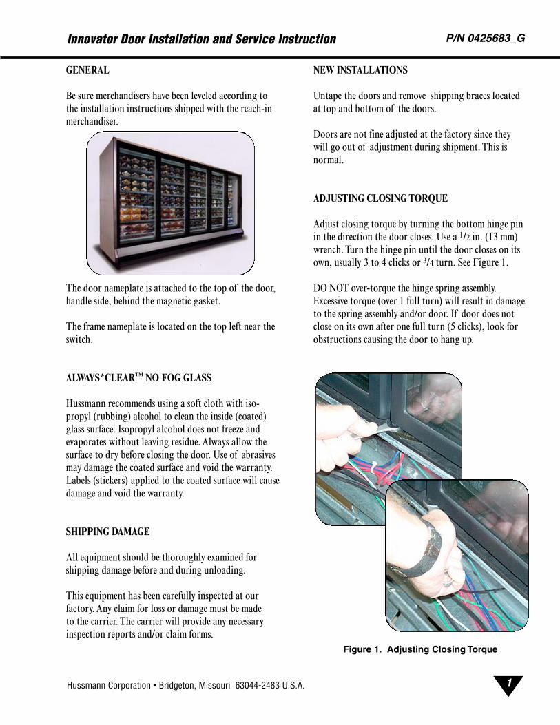
ADJUSTING CLOSING TORQUE
Adjust closing torque by turning the bottom hinge pin
in the direction the door closes. Use a 1/2 in. (13 mm)
wrench. Turn the hinge pin until the door closes on its
own, usually 3 to 4 clicks or 3/4 turn. See Figure 1.
DO NOT over-torque the hinge spring assembly.
Excessive torque (over 1 full turn) will result in damage
to the spring assembly and/or door. If door does not
close on its own after one full turn (5 clicks), look for
obstructions causing the door to hang up.
Innovator Door Installation and Service Instruction P/N 0425683_G
1
Figure 1. Adjusting Closing Torque
U.S. & Canada 1-800-922-1919 • Mexico 1-800-522-1900 • WWW.HUSSMANN.COM
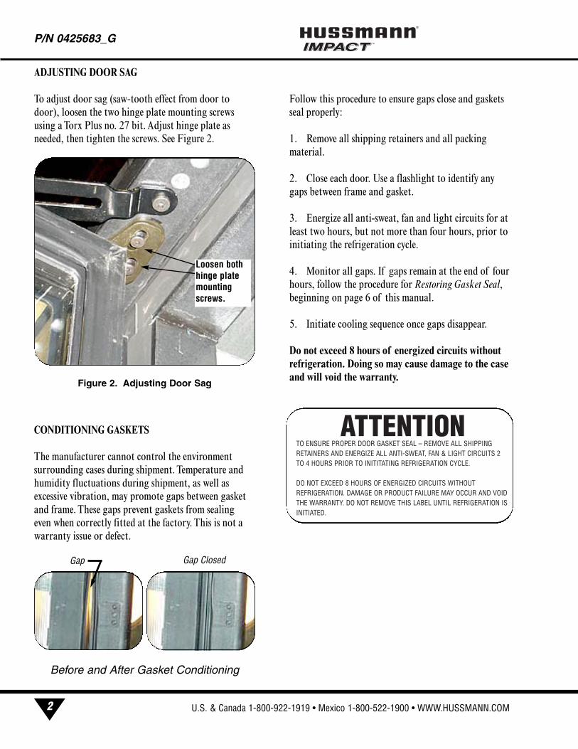
ADJUSTING DOOR SAG
To adjust door sag (saw-tooth effect from door to
door), loosen the two hinge plate mounting screws
using a Torx Plus no. 27 bit. Adjust hinge plate as
needed, then tighten the screws. See Figure 2.
CONDITIONING GASKETS
The manufacturer cannot control the environment
surrounding cases during shipment. Temperature and
humidity fluctuations during shipment, as well as
excessive vibration, may promote gaps between gasket
and frame. These gaps prevent gaskets from sealing
even when correctly fitted at the factory. This is not a
warranty issue or defect.
Follow this procedure to ensure gaps close and gaskets
seal properly:
1. Remove all shipping retainers and all packing
material.
2. Close each door. Use a flashlight to identify any
gaps between frame and gasket.
3. Energize all anti-sweat, fan and light circuits for at
least two hours, but not more than four hours, prior to
initiating the refrigeration cycle.
4. Monitor all gaps. If gaps remain at the end of four
hours, follow the procedure for Restoring Gasket Seal,beginning on page 6 of this manual.
5. Initiate cooling sequence once gaps disappear.
Do not exceed 8 hours of energized circuits withoutrefrigeration. Doing so may cause damage to the caseand will void the warranty.
P/N 0425683_G®
2
Figure 2. Adjusting Door Sag
Loosen bothhinge platemountingscrews.
Before and After Gasket Conditioning
Gap ClosedGap
ATTENTIONTO ENSURE PROPER DOOR GASKET SEAL – REMOVE ALL SHIPPINGRETAINERS AND ENERGIZE ALL ANTI-SWEAT, FAN & LIGHT CIRCUITS 2TO 4 HOURS PRIOR TO INITITATING REFRIGERATION CYCLE.
DO NOT EXCEED 8 HOURS OF ENERGIZED CIRCUITS WITHOUT REFRIGERATION. DAMAGE OR PRODUCT FAILURE MAY OCCUR AND VOIDTHE WARRANTY. DO NOT REMOVE THIS LABEL UNTIL REFRIGERATION ISINITIATED.
Hussmann Corporation • Bridgeton, Missouri 63044-2483 U.S.A.
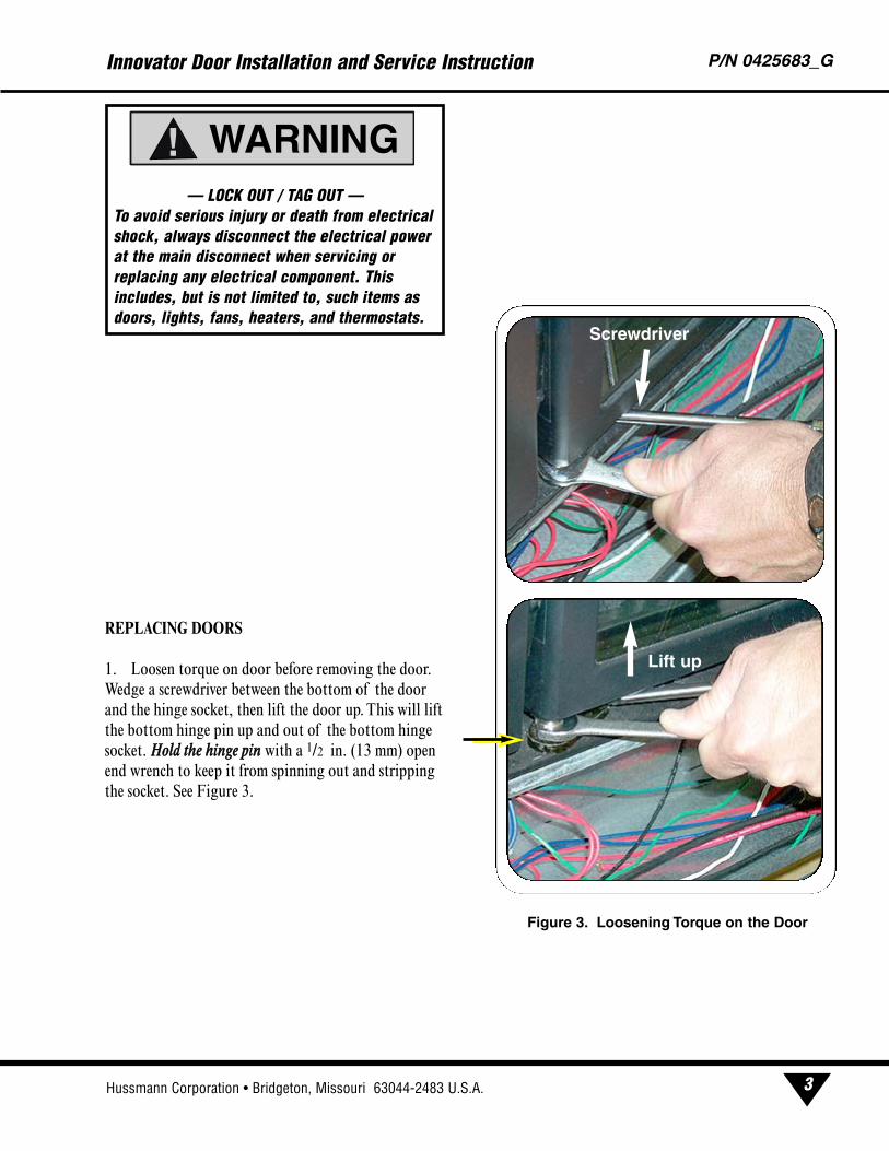
REPLACING DOORS
1. Loosen torque on door before removing the door.
Wedge a screwdriver between the bottom of the door
and the hinge socket, then lift the door up. This will lift
the bottom hinge pin up and out of the bottom hinge
socket. HHoolldd tthhee hhiinnggee ppiinn with a 1/2 in. (13 mm) open
end wrench to keep it from spinning out and stripping
the socket. See Figure 3.
Innovator Door Installation and Service Instruction P/N 0425683_G
3
Lift up
Screwdriver
Figure 3. Loosening Torque on the Door
— LOCK OUT / TAG OUT —To avoid serious injury or death from electricalshock, always disconnect the electrical powerat the main disconnect when servicing orreplacing any electrical component. Thisincludes, but is not limited to, such items asdoors, lights, fans, heaters, and thermostats.
WARNING!
U.S. & Canada 1-800-922-1919 • Mexico 1-800-522-1900 • WWW.HUSSMANN.COM
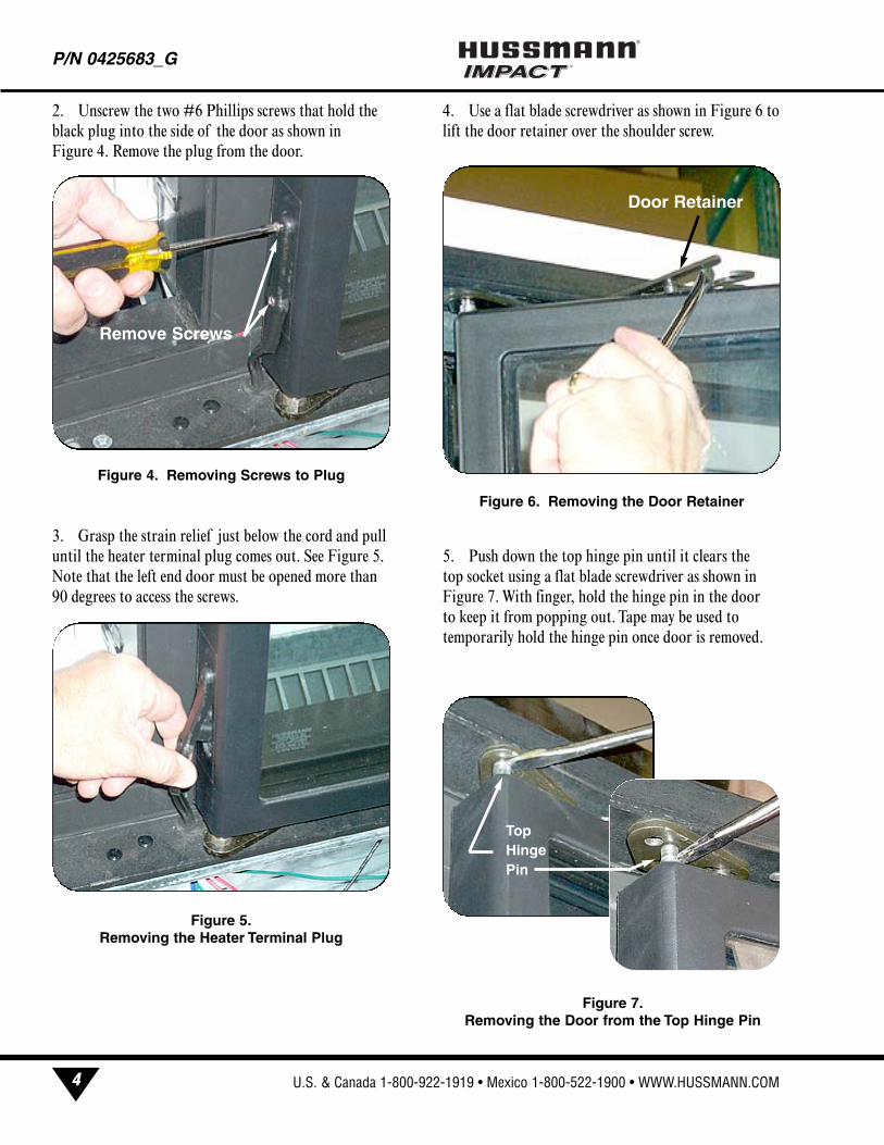
2. Unscrew the two #6 Phillips screws that hold the
black plug into the side of the door as shown in
Figure 4. Remove the plug from the door.
3. Grasp the strain relief just below the cord and pull
until the heater terminal plug comes out. See Figure 5.
Note that the left end door must be opened more than
90 degrees to access the screws.
4. Use a flat blade screwdriver as shown in Figure 6 to
lift the door retainer over the shoulder screw.
5. Push down the top hinge pin until it clears the
top socket using a flat blade screwdriver as shown in
Figure 7. With finger, hold the hinge pin in the door
to keep it from popping out. Tape may be used to
temporarily hold the hinge pin once door is removed.
P/N 0425683_G®
4
Figure 4. Removing Screws to Plug
Figure 5.Removing the Heater Terminal Plug
Remove Screws
Figure 6. Removing the Door Retainer
Door Retainer
Figure 7.Removing the Door from the Top Hinge Pin
Top Hinge Pin
Hussmann Corporation • Bridgeton, Missouri 63044-2483 U.S.A.
6. Rock the door out and pull the bottom hinge pin
out from the bottom socket.
7. Install the new door in reverse order.
8. Adjust the torque on the new door. If needed,
adjust sag.
REPLACING DOOR HINGE SPRING
The door must be removed before replacing the door
hinge spring.
Pull the hinge spring assembly out of the bottom of
the door and replace with a new assembly. See Figure 8.
Note that there are right-hand and left-hand hinge
spring assemblies.
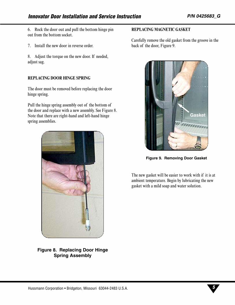
REPLACING MAGNETIC GASKET
Carefully remove the old gasket from the groove in the
back of the door, Figure 9.
The new gasket will be easier to work with if it is at
ambient temperature. Begin by lubricating the new
gasket with a mild soap and water solution.
Innovator Door Installation and Service Instruction P/N 0425683_G
5
Figure 8. Replacing Door Hinge Spring Assembly
Figure 9. Removing Door Gasket
Gasket
U.S. & Canada 1-800-922-1919 • Mexico 1-800-522-1900 • WWW.HUSSMANN.COM
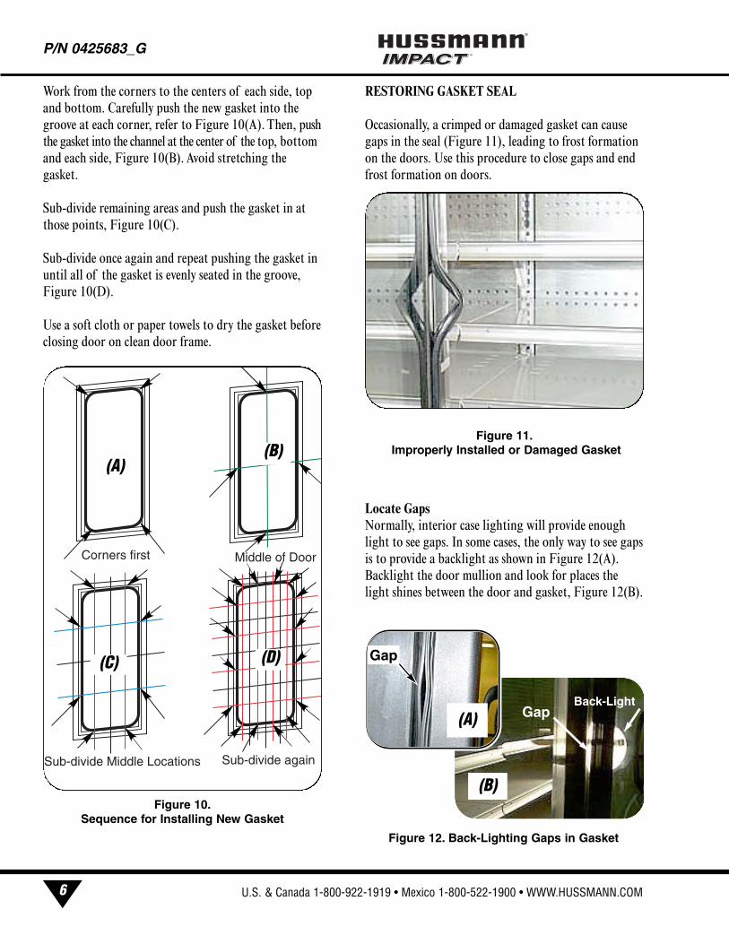
Work from the corners to the centers of each side, top
and bottom. Carefully push the new gasket into the
groove at each corner, refer to Figure 10(A). Then, push
the gasket into the channel at the center of the top, bottom
and each side, Figure 10(B). Avoid stretching the
gasket.
Sub-divide remaining areas and push the gasket in at
those points, Figure 10(C).
Sub-divide once again and repeat pushing the gasket in
until all of the gasket is evenly seated in the groove,
Figure 10(D).
Use a soft cloth or paper towels to dry the gasket before
closing door on clean door frame.
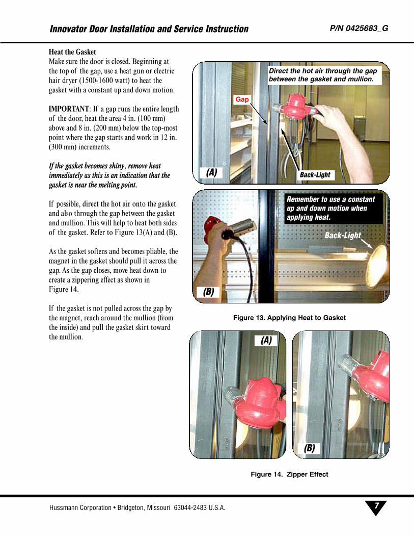
RESTORING GASKET SEAL
Occasionally, a crimped or damaged gasket can cause
gaps in the seal (Figure 11), leading to frost formation
on the doors. Use this procedure to close gaps and end
frost formation on doors.
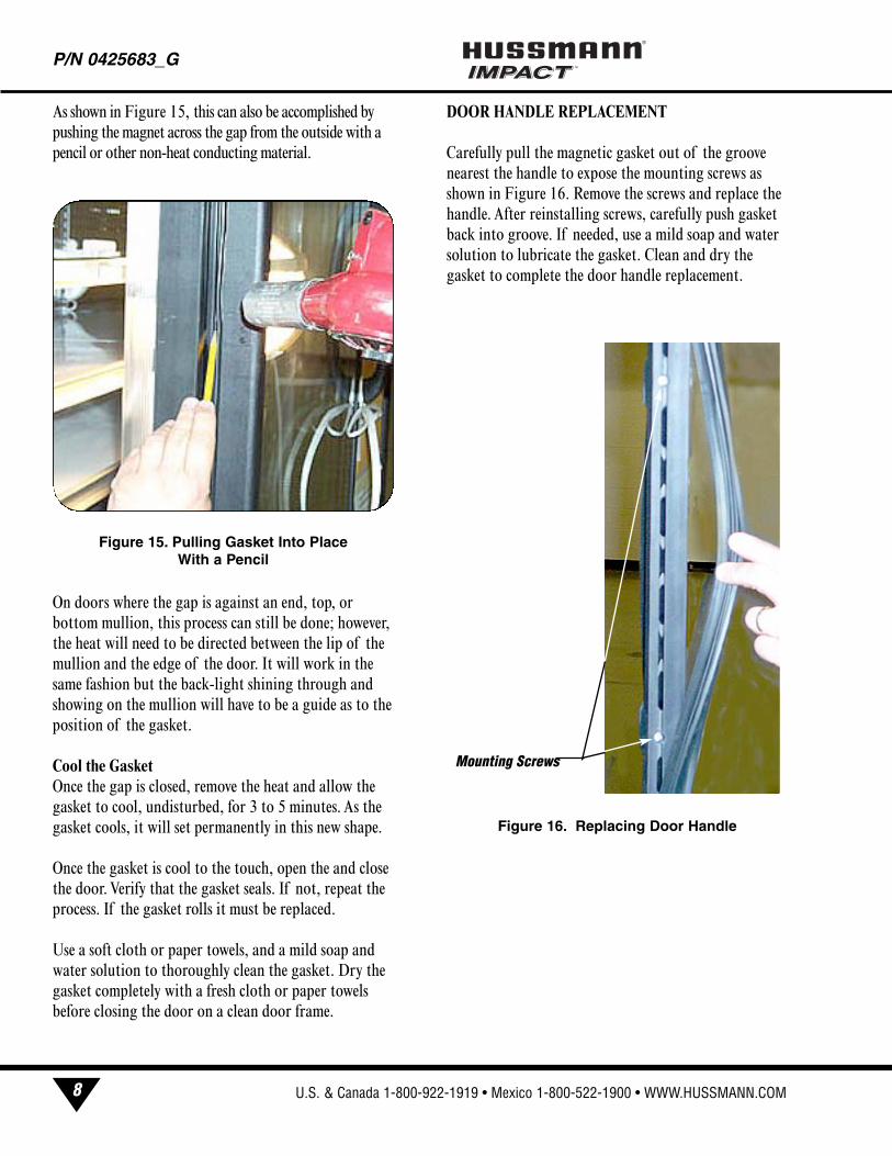
Locate GapsNormally, interior case lighting will provide enough
light to see gaps. In some cases, the only way to see gaps
is to provide a backlight as shown in Figure 12(A).
Backlight the door mullion and look for places the
light shines between the door and gasket, Figure 12(B).
P/N 0425683_G®
6
Corners first Middle of Door
Sub-divide Middle Locations Sub-divide again
Figure 10.Sequence for Installing New Gasket
(A)(B)
(C) (D)
Figure 11.Improperly Installed or Damaged Gasket
Figure 12. Back-Lighting Gaps in Gasket
Back-LightGap(A)
(B)
Gap
Hussmann Corporation • Bridgeton, Missouri 63044-2483 U.S.A.
Heat the GasketMake sure the door is closed. Beginning at
the top of the gap, use a heat gun or electric
hair dryer (1500-1600 watt) to heat the
gasket with a constant up and down motion.
IMPORTANT: If a gap runs the entire length
of the door, heat the area 4 in. (100 mm)
above and 8 in. (200 mm) below the top-most
point where the gap starts and work in 12 in.
(300 mm) increments.
IIff tthhee ggaasskkeett bbeeccoommeess sshhiinnyy,, rreemmoovvee hheeaattiimmmmeeddiiaatteellyy aass tthhiiss iiss aann iinnddiiccaattiioonn tthhaatt tthheeggaasskkeett iiss nneeaarr tthhee mmeellttiinngg ppooiinntt..
If possible, direct the hot air onto the gasket
and also through the gap between the gasket
and mullion. This will help to heat both sides
of the gasket. Refer to Figure 13(A) and (B).
As the gasket softens and becomes pliable, the
magnet in the gasket should pull it across the
gap. As the gap closes, move heat down to
create a zippering effect as shown in
Figure 14.
If the gasket is not pulled across the gap by
the magnet, reach around the mullion (from
the inside) and pull the gasket skirt toward
the mullion.
Innovator Door Installation and Service Instruction P/N 0425683_G
7
Gap
Back-Light
Direct the hot air through the gapbetween the gasket and mullion.
Back-Light
Remember to use a constantup and down motion whenapplying heat.
Figure 13. Applying Heat to Gasket
(A)
(B)
Figure 14. Zipper Effect
(A)
(B)
U.S. & Canada 1-800-922-1919 • Mexico 1-800-522-1900 • WWW.HUSSMANN.COM
As shown in Figure 15, this can also be accomplished by
pushing the magnet across the gap from the outside with a
pencil or other non-heat conducting material.
On doors where the gap is against an end, top, or
bottom mullion, this process can still be done; however,
the heat will need to be directed between the lip of the
mullion and the edge of the door. It will work in the
same fashion but the back-light shining through and
showing on the mullion will have to be a guide as to the
position of the gasket.
Cool the GasketOnce the gap is closed, remove the heat and allow the
gasket to cool, undisturbed, for 3 to 5 minutes. As the
gasket cools, it will set permanently in this new shape.
Once the gasket is cool to the touch, open the and close
the door. Verify that the gasket seals. If not, repeat the
process. If the gasket rolls it must be replaced.
Use a soft cloth or paper towels, and a mild soap and
water solution to thoroughly clean the gasket. Dry the
gasket completely with a fresh cloth or paper towels
before closing the door on a clean door frame.
DOOR HANDLE REPLACEMENT
Carefully pull the magnetic gasket out of the groove
nearest the handle to expose the mounting screws as
shown in Figure 16. Remove the screws and replace the
handle. After reinstalling screws, carefully push gasket
back into groove. If needed, use a mild soap and water
solution to lubricate the gasket. Clean and dry the
gasket to complete the door handle replacement.
P/N 0425683_G®
8
Figure 16. Replacing Door Handle
Mounting Screws
Figure 15. Pulling Gasket Into PlaceWith a Pencil
Hussmann Corporation • Bridgeton, Missouri 63044-2483 U.S.A.
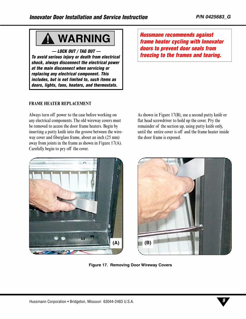
FRAME HEATER REPLACEMENT
Always turn off power to the case before working on
any electrical components. The old wireway covers must
be removed to access the door frame heaters. Begin by
inserting a putty knife into the groove between the wire-
way cover and fiberglass frame, about an inch (25 mm)
away from joints in the frame as shown in Figure 17(A).
Carefully begin to pry off the cover.
As shown in Figure 17(B), use a second putty knife or
flat head screwdriver to hold up the cover. Pry the
remainder of the section up, using putty knife only,
until the entire cover is off and the frame heater inside
the door frame is exposed.
Innovator Door Installation and Service Instruction P/N 0425683_G
9
— LOCK OUT / TAG OUT —To avoid serious injury or death from electricalshock, always disconnect the electrical powerat the main disconnect when servicing orreplacing any electrical component. Thisincludes, but is not limited to, such items asdoors, lights, fans, heaters, and thermostats.
WARNING!Hussmann recommends against frame heater cycling with Innovatordoors to prevent door seals fromfreezing to the frames and tearing.
Figure 17. Removing Door Wireway Covers
(B)(A)
U.S. & Canada 1-800-922-1919 • Mexico 1-800-522-1900 • WWW.HUSSMANN.COM
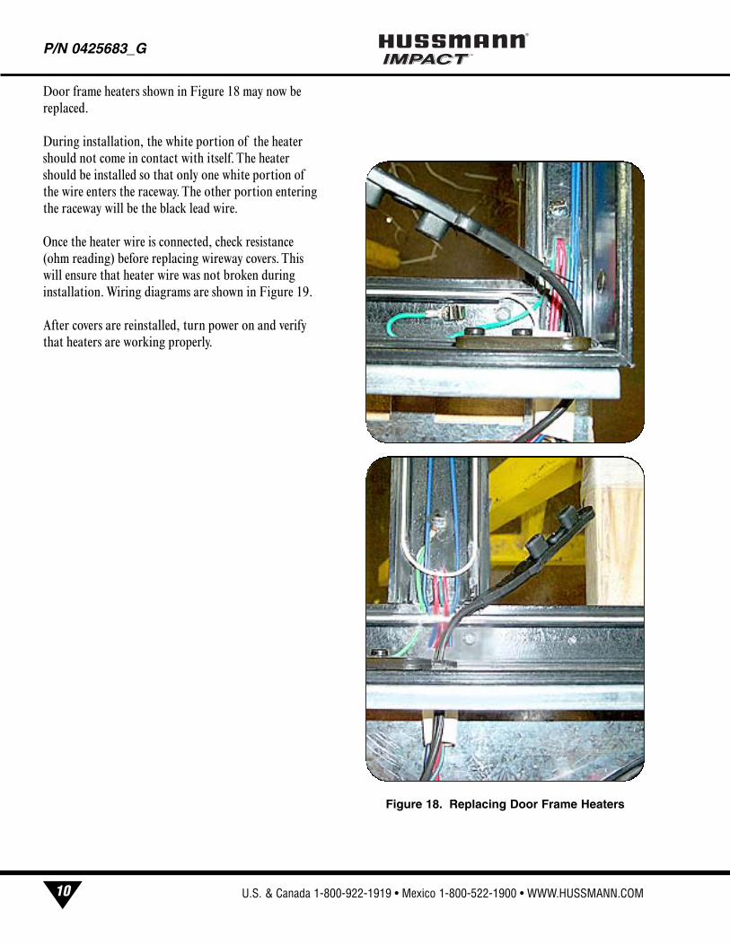
Door frame heaters shown in Figure 18 may now be
replaced.
During installation, the white portion of the heater
should not come in contact with itself. The heater
should be installed so that only one white portion of
the wire enters the raceway. The other portion entering
the raceway will be the black lead wire.
Once the heater wire is connected, check resistance
(ohm reading) before replacing wireway covers. This
will ensure that heater wire was not broken during
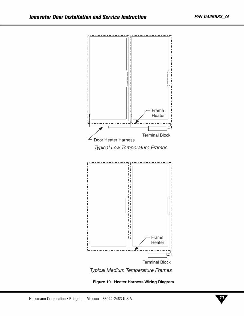
installation. Wiring diagrams are shown in Figure 19.
After covers are reinstalled, turn power on and verify
that heaters are working properly.
P/N 0425683_G®
10
Figure 18. Replacing Door Frame Heaters
Hussmann Corporation • Bridgeton, Missouri 63044-2483 U.S.A.
Innovator Door Installation and Service Instruction P/N 0425683_G
11
Door Heater HarnessTerminal Block
Typical Low Temperature Frames
Frame Heater
Typical Medium Temperature Frames
Terminal Block
Frame Heater
Figure 19. Heater Harness Wiring Diagram
U.S. & Canada 1-800-922-1919 • Mexico 1-800-522-1900 • WWW.HUSSMANN.COM
ALWAYS*BRIGHT™ LED FIXTURE
The new Always*Bright LED (light emitting diode)
lights work well for dimming or on/off operation using
an occupancy sensor (optional kits). They can be turned
on and off in a cold environment with no warm-up
time and no negative impact on lamp life.
Hussmann Always*Bright LED light fixtures normally
perform for up to 50,000 hours. That is 5.7 years of
continuous, 24 hour operation. They are backed by a
four-year materials warranty on the LED light strips
and a five-year materials warranty on the power supply.
ALWAYS*BRIGHT™ LED FIXTUREREPLACEMENT
1. Remove product from the case and store appropri-
ately.
2. Remove the wire racks from the case. Store them
out of the way of customers and store personnel.
3. Turn the light switch to OOFFFF. The switch is located
inside the case on the door mullion.
4. Lock out and tag out the circuit breaker for the
lighting circuit of the case where the LED fixtures are
installed.
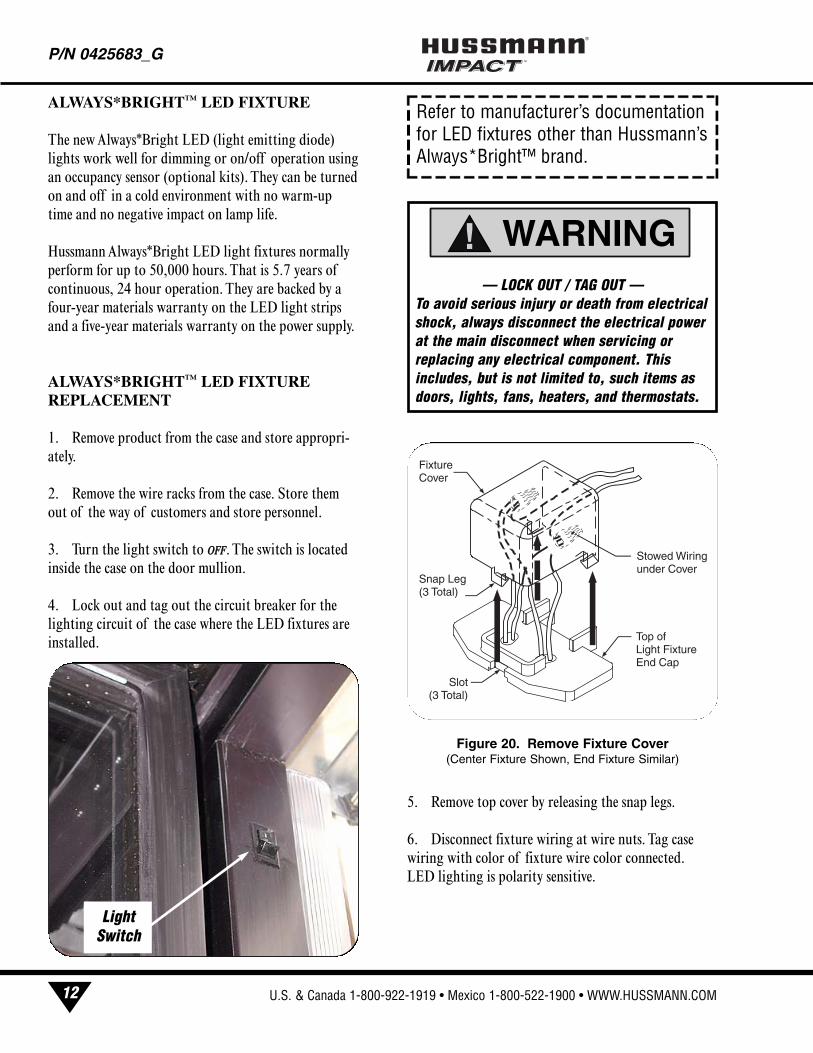
5. Remove top cover by releasing the snap legs.
6. Disconnect fixture wiring at wire nuts. Tag case
wiring with color of fixture wire color connected.
LED lighting is polarity sensitive.
P/N 0425683_G®
12
Figure 20. Remove Fixture Cover(Center Fixture Shown, End Fixture Similar)
— LOCK OUT / TAG OUT —To avoid serious injury or death from electricalshock, always disconnect the electrical powerat the main disconnect when servicing orreplacing any electrical component. Thisincludes, but is not limited to, such items asdoors, lights, fans, heaters, and thermostats.
WARNING!
LightSwitch
Fixture Cover
Top of Light Fixture End Cap
Stowed Wiring under Cover
Slot (3 Total)
Snap Leg (3 Total)
Refer to manufacturer’s documentationfor LED fixtures other than Hussmann’sAlways*Bright™ brand.
Hussmann Corporation • Bridgeton, Missouri 63044-2483 U.S.A.
LED light fixtures are polarity sensitive. The powersupply positive wire must be electrically connected tothe red wires of the LED fixture. The power supplynegative wire must be connected electrically to theblack wires. See Wiring Diagrams beginning onPage 15.
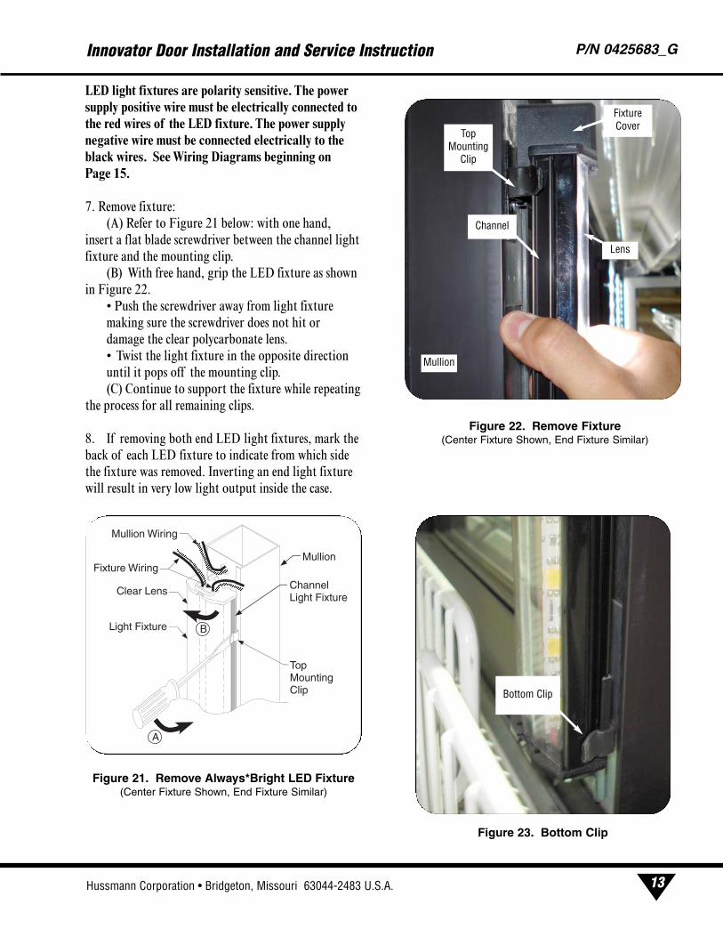
7. Remove fixture:
(A) Refer to Figure 21 below: with one hand,
insert a flat blade screwdriver between the channel light
fixture and the mounting clip.
(B) With free hand, grip the LED fixture as shown
in Figure 22.
• Push the screwdriver away from light fixture
making sure the screwdriver does not hit or
damage the clear polycarbonate lens.
• Twist the light fixture in the opposite direction
until it pops off the mounting clip.
(C) Continue to support the fixture while repeating
the process for all remaining clips.
8. If removing both end LED light fixtures, mark the
back of each LED fixture to indicate from which side
the fixture was removed. Inverting an end light fixture
will result in very low light output inside the case.
Innovator Door Installation and Service Instruction P/N 0425683_G
13
Light Fixture
Clear Lens Channel Light Fixture
Mullion
Top Mounting Clip
Mullion Wiring
Fixture Wiring
A
B
Figure 21. Remove Always*Bright LED Fixture(Center Fixture Shown, End Fixture Similar)
Figure 22. Remove Fixture (Center Fixture Shown, End Fixture Similar)
Figure 23. Bottom Clip
TopMounting
Clip
Channel
FixtureCover
Lens
Mullion
Bottom Clip
U.S. & Canada 1-800-922-1919 • Mexico 1-800-522-1900 • WWW.HUSSMANN.COM
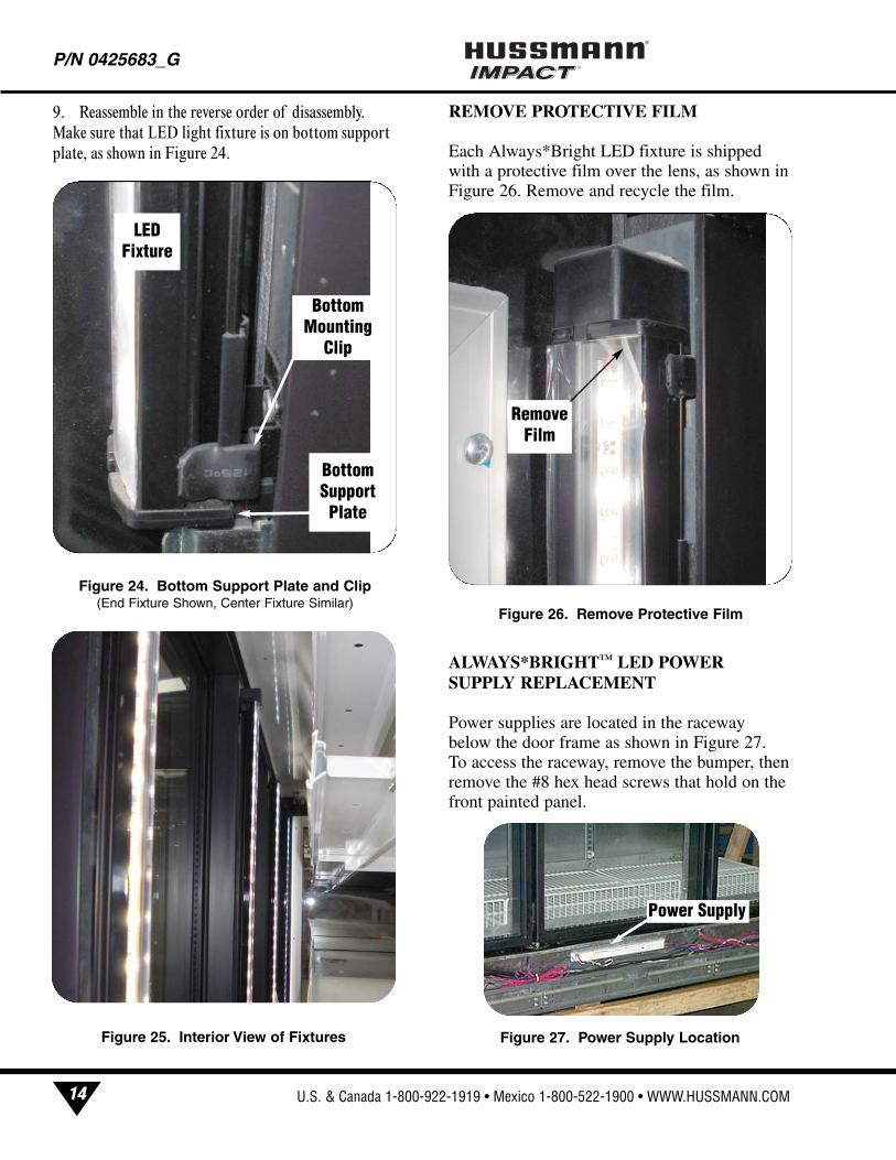
9. Reassemble in the reverse order of disassembly.
Make sure that LED light fixture is on bottom support
plate, as shown in Figure 24.
REMOVE PROTECTIVE FILM
Each Always*Bright LED fixture is shippedwith a protective film over the lens, as shown inFigure 26. Remove and recycle the film.
ALWAYS*BRIGHT™ LED POWERSUPPLY REPLACEMENT
Power supplies are located in the racewaybelow the door frame as shown in Figure 27. To access the raceway, remove the bumper, thenremove the #8 hex head screws that hold on thefront painted panel.
P/N 0425683_G®
14
Figure 27. Power Supply Location
Power Supply
Figure 24. Bottom Support Plate and Clip(End Fixture Shown, Center Fixture Similar)
Figure 26. Remove Protective Film
Remove
Film
BottomSupportPlate
LEDFixture
BottomMounting
Clip
Figure 25. Interior View of Fixtures
Hussmann Corporation • Bridgeton, Missouri 63044-2483 U.S.A.
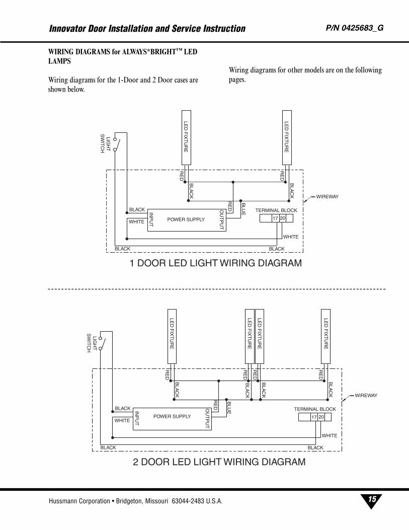
WIRING DIAGRAMS for ALWAYS*BRIGHT™ LEDLAMPS
Wiring diagrams for the 1-Door and 2 Door cases are
shown below.
Wiring diagrams for other models are on the following
pages.
Innovator Door Installation and Service Instruction P/N 0425683_G
15
WIREWAY
2017
RE
D
BLU
E
RE
D
RE
D
BLA
CK
BLA
CK
BLACK
WHITE
TERMINAL BLOCKINP
UT
OU
TP
UT
BLACK
BLACK
WHITE
LIGH
TS
WIT
CH
1 DOOR LED LIGHT WIRING DIAGRAM
LED
FIX
TU
RE
POWER SUPPLY
LED
FIX
TU
RE
WIREWAY
2017
RE
D
BLU
E
RE
D
RE
D
RE
D
BLA
CK
BLA
CK
RE
D
BLA
CK
BLA
CK
BLACK
WHITE
TERMINAL BLOCKINP
UT
OU
TP
UT
BLACK
BLACK
WHITE
LIGH
TS
WIT
CH
2 DOOR LED LIGHT WIRING DIAGRAM
LED
FIX
TU
RE
POWER SUPPLY
LED
FIX
TU
RE
LED
FIX
TU
RE
LED
FIX
TU
RE
U.S. & Canada 1-800-922-1919 • Mexico 1-800-522-1900 • WWW.HUSSMANN.COM
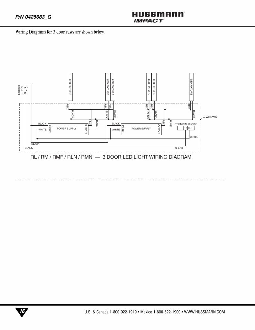
Wiring Diagrams for 3 door cases are shown below.
P/N 0425683_G®
16
WIREWAY
RE
D
BLU
E
RE
D
RE
D
BLA
CK
BLA
CK
RE
D
BLA
CK
BLA
CK
INP
UT
OU
TP
UT
BLACK
WHITE
LIGH
TS
WIT
CH
RL / RM / RMF / RLN / RMN
RE
D
RE
D
RE
D
BLA
CK
BLA
CK
TERMINAL BLOCK
RE
D
BLU
EINP
UT
OU
TP
UT
BLACK
WHITE 2017
WHITE
BLACK
BLACK
BLACK
LED
FIX
TU
RE
POWER SUPPLY POWER SUPPLY
LED
FIX
TU
RE
LED
FIX
TU
RE
LED
FIX
TU
RE
LED
FIX
TU
RE
LED
FIX
TU
RE
Hussmann Corporation • Bridgeton, Missouri 63044-2483 U.S.A.
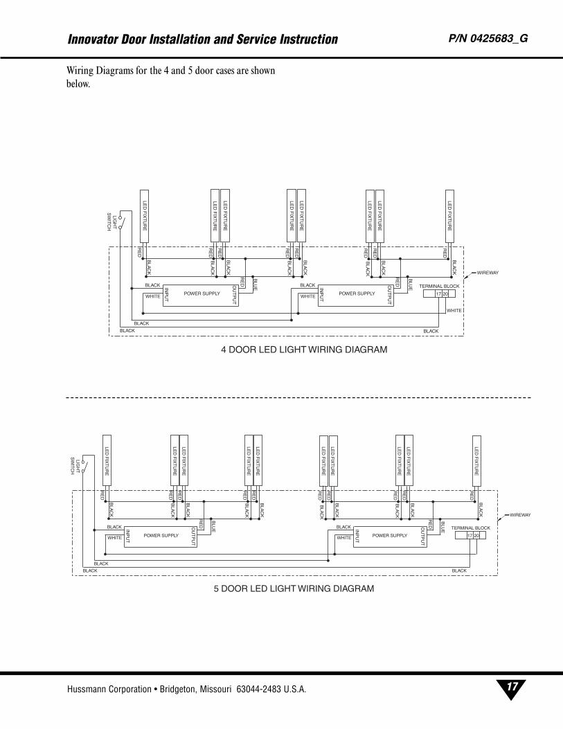
Wiring Diagrams for the 4 and 5 door cases are shown
below.
Innovator Door Installation and Service Instruction P/N 0425683_G
17
WIREWAY
RE
D
BLU
E
RE
D
RE
D
BLA
CK
BLA
CK
RE
D
BLA
CK
BLA
CK
INP
UT
OU
TP
UT
BLACK
WHITE
LIGH
TS
WIT
CH
4 DOOR LED LIGHT WIRING DIAGRAM
RE
D
RE
D
RE
D
BLA
CK
BLA
CK
TERMINAL BLOCK
RE
D
BLU
EINP
UT
OU
TP
UT
BLACK
WHITE 2017
RE
DB
LAC
K
RE
D
BLA
CK
BLACK
BLACK
WHITE
BLACK
LED
FIX
TU
RE
POWER SUPPLY
LED
FIX
TU
RE
LED
FIX
TU
RE
LED
FIX
TU
RE
LED
FIX
TU
RE
LED
FIX
TU
RE
LED
FIX
TU
RE
LED
FIX
TU
RE
POWER SUPPLY
WIREWAY
RE
D
BLU
E
RE
D
RE
D
BLA
CK
BLA
CK
RE
D
BLA
CK
BLA
CK
INP
UT
OU
TP
UT
BLACK
WHITE
LIGH
TS
WIT
CH
5 DOOR LED LIGHT WIRING DIAGRAM
RE
D
RE
D
RE
D
BLA
CK
BLA
CK
TERMINAL BLOCK
RE
D
BLU
EINP
UT
OU
TP
UT
BLACK
WHITE
RE
DB
LAC
K
RE
D
BLA
CK
BLA
CK
RE
D
RE
D
BLA
CK
BLACK
BLACK
17 20
BLACK
LED
FIX
TU
RE
POWER SUPPLYPOWER SUPPLY
LED
FIX
TU
RE
LED
FIX
TU
RE
LED
FIX
TU
RE
LED
FIX
TU
RE
LED
FIX
TU
RE
LED
FIX
TU
RE
LED
FIX
TU
RE
LED
FIX
TU
RE
LED
FIX
TU
RE
U.S. & Canada 1-800-922-1919 • Mexico 1-800-522-1900 • WWW.HUSSMANN.COM
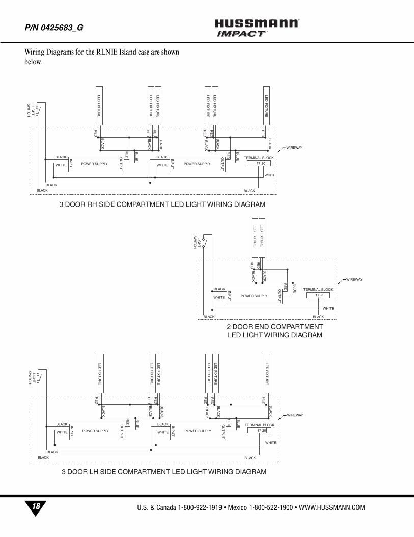
Wiring Diagrams for the RLNIE Island case are shown
below.
P/N 0425683_G®
18
3 DOOR RH SIDE COMPARTMENT LED LIGHT WIRING DIAGRAM
WIREWAY
RE
D
BLU
E
RE
D
RE
D
BLA
CK
BLA
CK
RE
D
BLA
CK
BLA
CK
INP
UT
OU
TP
UT
BLACK
WHITE
LIGH
TS
WIT
CH
RE
D
RE
D
RE
D
BLA
CK
BLA
CK
TERMINAL BLOCK
RE
D
BLU
EINP
UT
OU
TP
UT
BLACK
WHITE 2017
WHITE
BLACK
BLACK
BLACK
LED
FIX
TU
RE
POWER SUPPLY POWER SUPPLY
LED
FIX
TU
RE
LED
FIX
TU
RE
LED
FIX
TU
RE
LED
FIX
TU
RE
LED
FIX
TU
RE
WIREWAY
2017
RE
D
BLU
E
BLACK
WHITE
TERMINAL BLOCKINP
UT
OU
TP
UT
BLACK
BLACK
WHITE
LIGH
TS
WIT
CH
2 DOOR END COMPARTMENT LED LIGHT WIRING DIAGRAM
POWER SUPPLY
RE
DB
LAC
K
RE
D
BLA
CK
LED
FIX
TU
RE
LED
FIX
TU
RE
3 DOOR LH SIDE COMPARTMENT LED LIGHT WIRING DIAGRAM
WIREWAY
RE
D
BLU
E
RE
D
RE
D
BLA
CK
BLA
CK
RE
D
BLA
CK
BLA
CK
INP
UT
OU
TP
UT
BLACK
WHITE
LIGH
TS
WIT
CH
RE
D
RE
D
RE
D
BLA
CK
BLA
CK
TERMINAL BLOCK
RE
D
BLU
EINP
UT
OU
TP
UT
BLACK
WHITE 2017
WHITE
BLACK
BLACK
BLACK
LED
FIX
TU
RE
POWER SUPPLY POWER SUPPLY
LED
FIX
TU
RE
LED
FIX
TU
RE
LED
FIX
TU
RE
LED
FIX
TU
RE
LED
FIX
TU
RE
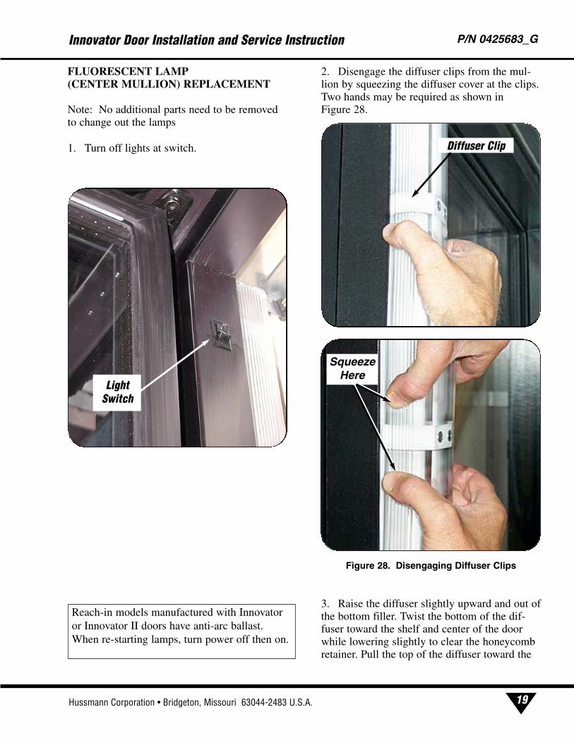
FLUORESCENT LAMP (CENTER MULLION) REPLACEMENT
Note: No additional parts need to be removedto change out the lamps
1. Turn off lights at switch.
2. Disengage the diffuser clips from the mul-lion by squeezing the diffuser cover at the clips.Two hands may be required as shown inFigure 28.
3. Raise the diffuser slightly upward and out ofthe bottom filler. Twist the bottom of the dif-fuser toward the shelf and center of the doorwhile lowering slightly to clear the honeycomb retainer. Pull the top of the diffuser toward the
Innovator Door Installation and Service Instruction P/N 0425683_G
19Hussmann Corporation • Bridgeton, Missouri 63044-2483 U.S.A.
Reach-in models manufactured with Innovatoror Innovator II doors have anti-arc ballast.When re-starting lamps, turn power off then on.
Figure 28. Disengaging Diffuser Clips
Squeeze Here
Diffuser Clip
LightSwitch
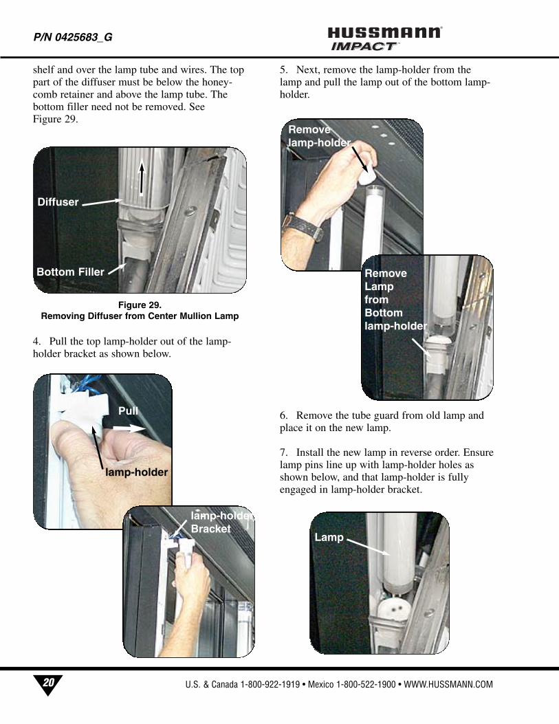
shelf and over the lamp tube and wires. The toppart of the diffuser must be below the honey-comb retainer and above the lamp tube. Thebottom filler need not be removed. SeeFigure 29.
4. Pull the top lamp-holder out of the lamp-holder bracket as shown below.
5. Next, remove the lamp-holder from thelamp and pull the lamp out of the bottom lamp-holder.
6. Remove the tube guard from old lamp andplace it on the new lamp.
7. Install the new lamp in reverse order. Ensurelamp pins line up with lamp-holder holes asshown below, and that lamp-holder is fullyengaged in lamp-holder bracket.
P/N 0425683_G®
20 U.S. & Canada 1-800-922-1919 • Mexico 1-800-522-1900 • WWW.HUSSMANN.COM
Pull
lamp-holderBracket
lamp-holder
Lamp
Removelamp-holder
RemoveLampfromBottomlamp-holder
Figure 29.Removing Diffuser from Center Mullion Lamp
Diffuser
Bottom Filler
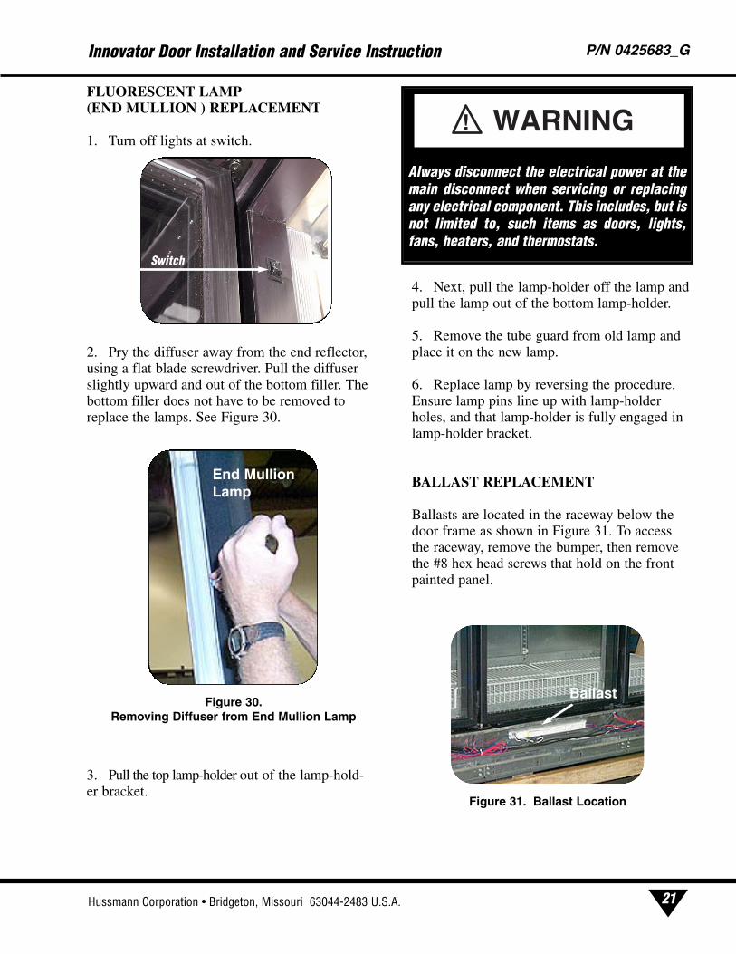
FLUORESCENT LAMP (END MULLION ) REPLACEMENT
1. Turn off lights at switch.
2. Pry the diffuser away from the end reflector,using a flat blade screwdriver. Pull the diffuserslightly upward and out of the bottom filler. Thebottom filler does not have to be removed toreplace the lamps. See Figure 30.
3. Pull the top lamp-holder out of the lamp-hold-er bracket.
4. Next, pull the lamp-holder off the lamp andpull the lamp out of the bottom lamp-holder.
5. Remove the tube guard from old lamp andplace it on the new lamp.
6. Replace lamp by reversing the procedure.Ensure lamp pins line up with lamp-holderholes, and that lamp-holder is fully engaged inlamp-holder bracket.
BALLAST REPLACEMENT
Ballasts are located in the raceway below thedoor frame as shown in Figure 31. To accessthe raceway, remove the bumper, then removethe #8 hex head screws that hold on the frontpainted panel.
Innovator Door Installation and Service Instruction P/N 0425683_G
21Hussmann Corporation • Bridgeton, Missouri 63044-2483 U.S.A.
Figure 31. Ballast Location
Ballast
Always disconnect the electrical power at themain disconnect when servicing or replacingany electrical component. This includes, but isnot limited to, such items as doors, lights,fans, heaters, and thermostats.
WARNING!
Figure 30.Removing Diffuser from End Mullion Lamp
End MullionLamp
Switch

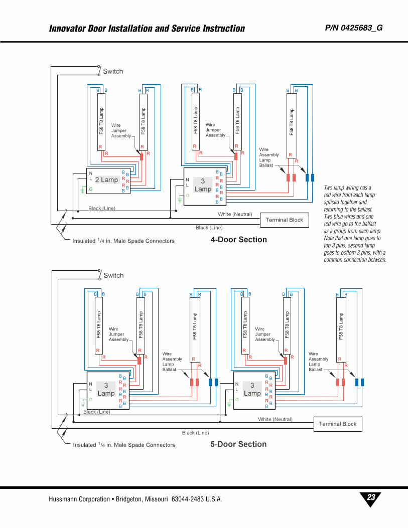
Wiring Diagrams for 120V Electronic Ballast
P/N 0425683_G®
22 U.S. & Canada 1-800-922-1919 • Mexico 1-800-522-1900 • WWW.HUSSMANN.COM
F58
T8
Lam
p
F58
T8
Lam
p
F58
T8
Lam
p
F58
T8
Lam
pF
58 T
8 La
mp
F58
T8
Lam
p
F58
T8
Lam
p
Two lamp wiring has a red wire from each lamp spliced together and returning to the ballast. Two blue wires and one red wire go to the ballast as a group from each lamp. Note that one lamp goes to top 3 pins, second lamp goes to bottom 3 pins, with acommon connection between.
Innovator Door Installation and Service Instruction P/N 0425683_G
23Hussmann Corporation • Bridgeton, Missouri 63044-2483 U.S.A.
F58
T8
Lam
p
F58
T8
Lam
p
F58
T8
Lam
p
F58
T8
Lam
p
F58
T8
Lam
p
F58
T8
Lam
p
F58
T8
Lam
p
F58
T8
Lam
p
F58
T8
Lam
p
F58
T8
Lam
p
F58
T8
Lam
p
Two lamp wiring has a red wire from each lamp spliced together and returning to the ballast. Two blue wires and one red wire go to the ballast as a group from each lamp. Note that one lamp goes to top 3 pins, second lamp goes to bottom 3 pins, with acommon connection between.
P/N 0425683_G®
24 U.S. & Canada 1-800-922-1919 • Mexico 1-800-522-1900 • WWW.HUSSMANN.COM
Door Retainer
Harness, Female
Receptacle
(not used with medium
temperature or Innovator II)
Screw, Case End Shoulder
Washer, Flat
Torsion Assembly
Screw, Socket
Retainer
Screw, Hold-open Shoulder
Spring, Top
Hinge Pin
Bushing, Top
Hinge Pin
Bushing, Bottom
Hinge Pin
Closer, Door
Cover, Wireway
Heater, Frame Wire
Lamp Holder,
Top
Lamp Holder, Bottom
Socket, Top Hinge Socket, Bottom Hinge
Pin, Top Hinge
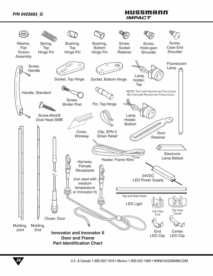
Innovator and Innovator II Door and Frame
Part Identification Chart
NOTE: TOP LAMP HOLDER HAS TWO LEADS, BOTTOM LAMP HOLDER HAS THREE LEADS.
Clip, SPN 5 Strain Relief
Screw, Handle
Handle, Standard
Molding, Joint
Molding, End
Screw, Binder Post
Electronic Lamp Ballast
Fluorescent Lamp
Screw,#6x5/8 Oval Head SMB
LED Light
Center LED Clip
End LED Clip
24VDC LED Power Supply
Top and Side Views
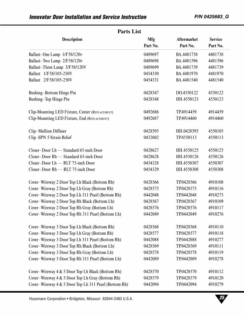
Ballast–One Lamp 1/F58/120v 0489697 BA.4481738 4481738
Ballast–Two Lamp 2/F58/120v 0489698 BA.4481596 4481596
Ballast–Three Lamp 3/F58/120V 0489699 BA.4481739 4481739
Ballast 1/F58/105-250V 0454330 BA.4481970 4481970
Ballast 2/F58/105-250V 0454331 BA.4481540 4481540
Bushing–Bottom Hinge Pin 0428547 DO.4550122 4550122
Bushing–Top Hinge Pin 0428548 HH.4550123 4550123
Clip-Mounting LED Fixture, Center (REPLACEMENT) 0492686 TP.4914459 4914459
Clip-Mounting LED Fixture, End (REPLACEMENT) 0492687 TP.4914460 4914460
Clip–Mullion Diffuser 0428595 HH.0428595 4550105
Clip–SPN 5 Strain Relief 0432602 TP.4550113 4550113
Closer–Door Lh — Standard 65-inch Door 0428627 HH.4550125 4550125
Closer–Door Rh — Standard 65-inch Door 0428628 HH.4550126 4550126
Closer–Door Lh — RLT 75-inch Door 0454328 HH.4550307 4550307
Closer–Door Rh — RLT 75-inch Door 0454329 HH.4550308 4550308
Cover–Wireway 2 Door Top Lh Black (Bottom Rh) 0428566 TP.0428566 4910108
Cover–Wireway 2 Door Top Lh Gray (Bottom Rh) 0428575 TP.0428575 4910116
Cover–Wireway 2 Door Top Lh 311 Pearl (Bottom Rh) 0442048 TP.0442048 4910275
Cover–Wireway 2 Door Top Rh Black (Bottom Lh) 0428567 TP.0428567 4910109
Cover–Wireway 2 Door Top Rh Gray (Bottom Lh) 0428576 TP.0428576 4910117
Cover–Wireway 2 Door Top Rh 311 Pearl (Bottom Lh) 0442049 TP.0442049 4910276
Cover–Wireway 3 Door Top Lh Black (Bottom Rh) 0428568 TP.0428568 4910110
Cover–Wireway 3 Door Top Lh Gray (Bottom Rh) 0428577 TP.0428577 4910118
Cover–Wireway 3 Door Top Lh 311 Pearl (Bottom Rh) 0442088 TP.0442088 4910277
Cover–Wireway 3 Door Top Rh Black (Bottom Lh) 0428569 TP.0428569 4910111
Cover–Wireway 3 Door Top Rh Gray (Bottom Lh) 0428578 TP.0428578 4910119
Cover–Wireway 3 Door Top Rh 311 Pearl (Bottom Lh) 0442089 TP.0442089 4910278
Cover–Wireway 4 & 5 Door Top Lh Black (Bottom Rh) 0428570 TP.0428570 4910112
Cover–Wireway 4 & 5 Door Top Lh Gray (Bottom Rh) 0428579 TP.0428579 4910120
Cover–Wireway 4 & 5 Door Top Lh 311 Pearl (Bottom Rh) 0442094 TP.0442094 4910279
Innovator Door Installation and Service Instruction P/N 0425683_G
25Hussmann Corporation • Bridgeton, Missouri 63044-2483 U.S.A.
Parts ListDescription Mfg Aftermarket Service
Part No. Part No. Part No.
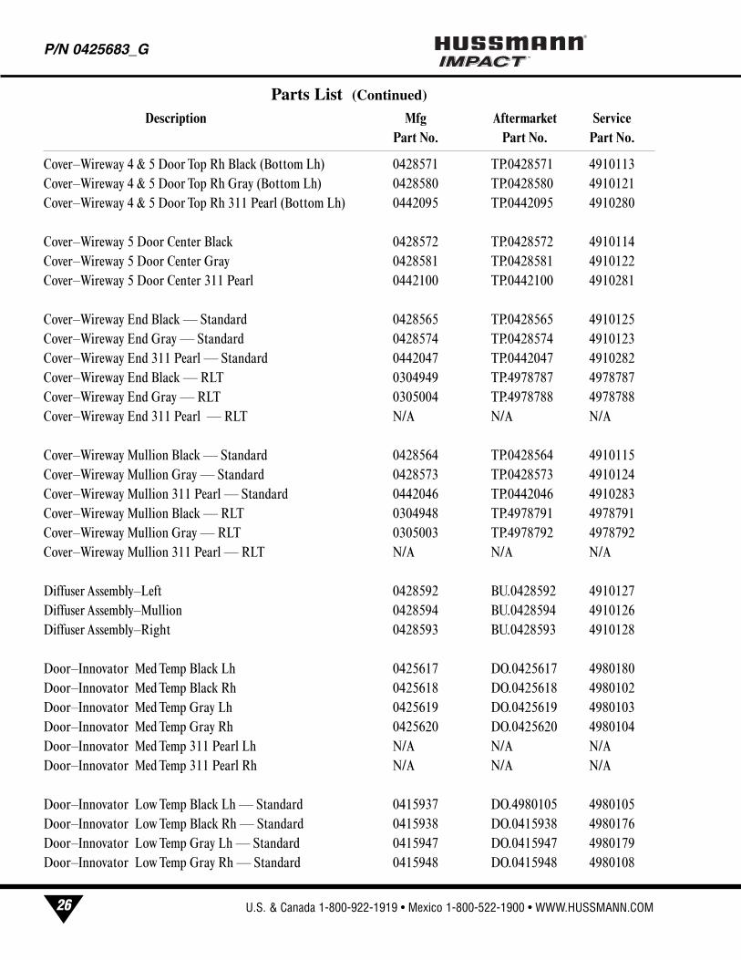
Cover–Wireway 4 & 5 Door Top Rh Black (Bottom Lh) 0428571 TP.0428571 4910113
Cover–Wireway 4 & 5 Door Top Rh Gray (Bottom Lh) 0428580 TP.0428580 4910121
Cover–Wireway 4 & 5 Door Top Rh 311 Pearl (Bottom Lh) 0442095 TP.0442095 4910280
Cover–Wireway 5 Door Center Black 0428572 TP.0428572 4910114
Cover–Wireway 5 Door Center Gray 0428581 TP.0428581 4910122
Cover–Wireway 5 Door Center 311 Pearl 0442100 TP.0442100 4910281
Cover–Wireway End Black — Standard 0428565 TP.0428565 4910125
Cover–Wireway End Gray — Standard 0428574 TP.0428574 4910123
Cover–Wireway End 311 Pearl — Standard 0442047 TP.0442047 4910282
Cover–Wireway End Black — RLT 0304949 TP.4978787 4978787
Cover–Wireway End Gray — RLT 0305004 TP.4978788 4978788
Cover–Wireway End 311 Pearl — RLT N/A N/A N/A
Cover–Wireway Mullion Black — Standard 0428564 TP.0428564 4910115
Cover–Wireway Mullion Gray — Standard 0428573 TP.0428573 4910124
Cover–Wireway Mullion 311 Pearl — Standard 0442046 TP.0442046 4910283
Cover–Wireway Mullion Black — RLT 0304948 TP.4978791 4978791
Cover–Wireway Mullion Gray — RLT 0305003 TP.4978792 4978792
Cover–Wireway Mullion 311 Pearl — RLT N/A N/A N/A
Diffuser Assembly–Left 0428592 BU.0428592 4910127
Diffuser Assembly–Mullion 0428594 BU.0428594 4910126
Diffuser Assembly–Right 0428593 BU.0428593 4910128
Door–Innovator Med Temp Black Lh 0425617 DO.0425617 4980180
Door–Innovator Med Temp Black Rh 0425618 DO.0425618 4980102
Door–Innovator Med Temp Gray Lh 0425619 DO.0425619 4980103
Door–Innovator Med Temp Gray Rh 0425620 DO.0425620 4980104
Door–Innovator Med Temp 311 Pearl Lh N/A N/A N/A
Door–Innovator Med Temp 311 Pearl Rh N/A N/A N/A
Door–Innovator Low Temp Black Lh — Standard 0415937 DO.4980105 4980105
Door–Innovator Low Temp Black Rh — Standard 0415938 DO.0415938 4980176
Door–Innovator Low Temp Gray Lh — Standard 0415947 DO.0415947 4980179
Door–Innovator Low Temp Gray Rh — Standard 0415948 DO.0415948 4980108
P/N 0425683_G®
26 U.S. & Canada 1-800-922-1919 • Mexico 1-800-522-1900 • WWW.HUSSMANN.COM
Parts List (Continued)
Description Mfg Aftermarket ServicePart No. Part No. Part No.
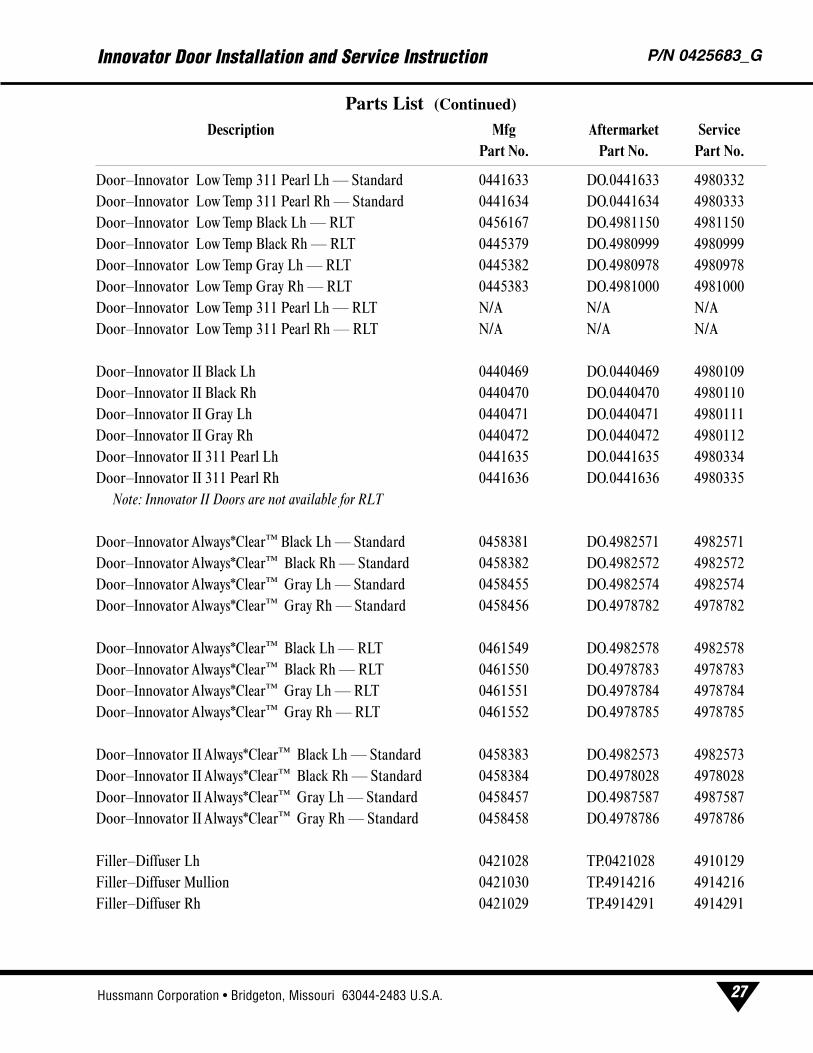
Door–Innovator Low Temp 311 Pearl Lh — Standard 0441633 DO.0441633 4980332
Door–Innovator Low Temp 311 Pearl Rh — Standard 0441634 DO.0441634 4980333
Door–Innovator Low Temp Black Lh — RLT 0456167 DO.4981150 4981150
Door–Innovator Low Temp Black Rh — RLT 0445379 DO.4980999 4980999
Door–Innovator Low Temp Gray Lh — RLT 0445382 DO.4980978 4980978
Door–Innovator Low Temp Gray Rh — RLT 0445383 DO.4981000 4981000
Door–Innovator Low Temp 311 Pearl Lh — RLT N/A N/A N/A
Door–Innovator Low Temp 311 Pearl Rh — RLT N/A N/A N/A
Door–Innovator II Black Lh 0440469 DO.0440469 4980109
Door–Innovator II Black Rh 0440470 DO.0440470 4980110
Door–Innovator II Gray Lh 0440471 DO.0440471 4980111
Door–Innovator II Gray Rh 0440472 DO.0440472 4980112
Door–Innovator II 311 Pearl Lh 0441635 DO.0441635 4980334
Door–Innovator II 311 Pearl Rh 0441636 DO.0441636 4980335
Note: Innovator II Doors are not available for RLT
Door–Innovator Always*Clear™ Black Lh — Standard 0458381 DO.4982571 4982571
Door–Innovator Always*Clear™ Black Rh — Standard 0458382 DO.4982572 4982572
Door–Innovator Always*Clear™ Gray Lh — Standard 0458455 DO.4982574 4982574
Door–Innovator Always*Clear™ Gray Rh — Standard 0458456 DO.4978782 4978782
Door–Innovator Always*Clear™ Black Lh — RLT 0461549 DO.4982578 4982578
Door–Innovator Always*Clear™ Black Rh — RLT 0461550 DO.4978783 4978783
Door–Innovator Always*Clear™ Gray Lh — RLT 0461551 DO.4978784 4978784
Door–Innovator Always*Clear™ Gray Rh — RLT 0461552 DO.4978785 4978785
Door–Innovator II Always*Clear™ Black Lh — Standard 0458383 DO.4982573 4982573
Door–Innovator II Always*Clear™ Black Rh — Standard 0458384 DO.4978028 4978028
Door–Innovator II Always*Clear™ Gray Lh — Standard 0458457 DO.4987587 4987587
Door–Innovator II Always*Clear™ Gray Rh — Standard 0458458 DO.4978786 4978786
Filler–Diffuser Lh 0421028 TP.0421028 4910129
Filler–Diffuser Mullion 0421030 TP.4914216 4914216
Filler–Diffuser Rh 0421029 TP.4914291 4914291
Innovator Door Installation and Service Instruction P/N 0425683_G
27Hussmann Corporation • Bridgeton, Missouri 63044-2483 U.S.A.
Parts List (Continued)
Description Mfg Aftermarket ServicePart No. Part No. Part No.
Gasket–Black Magnetic — Standard 0428562 GA.4330101 4330101
Gasket–Gray Magnetic — Standard 0428563 GA.4330102 4330102
Gasket–Black Magnetic — RLT 0461957 GA.4330208 4330208
Gasket–Gray Magnetic — RLT 0461958 GA.4330207 4330207
Handle–Standard Black Door 0428559 HH.0428559 4910106
Handle–Standard Gray Door 0428561 HH.4910107 4910107
Handle–Standard 311 Pearl Door 0441686 HH.4914279 4914279
Harness–Ballast Supply 2 Door 0430293 ES.0430293 4440112
Harness–Ballast Supply 3 Door 0430294 ES.0430294 4440113
Harness–Ballast Supply 4 Door 0430295 ES.0430295 4440114
Harness–Ballast Supply 5 Door 0430296 ES.0430296 4440115
Harness–Door Heater 2 Door 0432596 ES.0432596 4440108
Harness–Door Heater 3 Door 0432597 ES.0432597 4440109
Harness–Door Heater 4 Door 0432598 ES.0432598 4440110
Harness–Door Heater 5 Door 0432599 ES.0432599 4440111
Harness–Female Receptacle Black 0432600 ES.0432600 4440104
Harness–Female Receptacle Gray 0432601 ES.0432601 4440105
Harness–Female Receptacle 311 Pearl N/A N/A N/A
Harness–Opposite Swing Black 0432612 ES.0432612 4440106
Harness–Opposite Swing Gray 0432613 ES.0432613 4440107
Harness–Opposite Swing 311 Pearl N/A N/A N/A
Heater–Frame Wire 2 Door Innovator Low Temp — Standard 0428601 HE.4480101 4480101
Heater–Frame Wire 3 Door Innovator Low Temp — Standard 0428602 HE.4480102 4480102
Heater–Frame Wire 4 Door Innovator Low Temp — Standard 0428603 HE.4480103 4480103
Heater–Frame Wire 5 Door Innovator Low Temp — Standard 0428604 HE.4480104 4480104
Heater–Frame Wire 2 Door Innovator — RLT 0458438 HE.4850651 4850651
Heater–Frame Wire 3 Door Innovator — RLT 0458439 HE.4850610 4850610
Heater–Frame Wire 4 Door Innovator — RLT 0458440 HE.4850652 4850652
Heater–Frame Wire 5 Door Innovator — RLT 0458441 HE.4850611 4850611
P/N 0425683_G®
28 U.S. & Canada 1-800-922-1919 • Mexico 1-800-522-1900 • WWW.HUSSMANN.COM
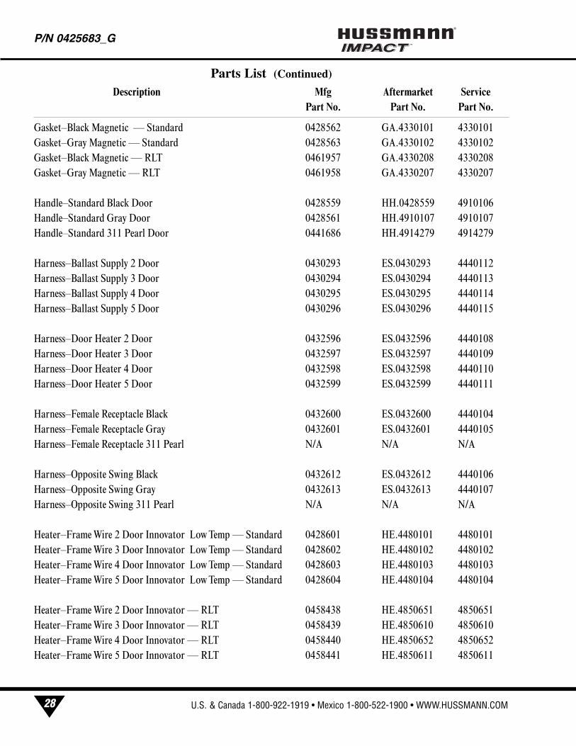
Parts List (Continued)
Description Mfg Aftermarket ServicePart No. Part No. Part No.
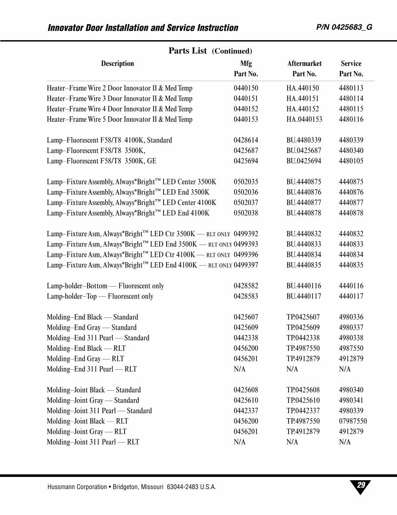
Heater–Frame Wire 2 Door Innovator II & Med Temp 0440150 HA.440150 4480113
Heater–Frame Wire 3 Door Innovator II & Med Temp 0440151 HA.440151 4480114
Heater–Frame Wire 4 Door Innovator II & Med Temp 0440152 HA.440152 4480115
Heater–Frame Wire 5 Door Innovator II & Med Temp 0440153 HA.0440153 4480116
Lamp–Fluorescent F58/T8 4100K, Standard 0428614 BU.4480339 4480339
Lamp–Fluorescent F58/T8 3500K, 0425687 BU.0425687 4480340
Lamp–Fluorescent F58/T8 3500K, GE 0425694 BU.0425694 4480105
Lamp–Fixture Assembly, Always*Bright™ LED Center 3500K 0502035 BU.4440875 4440875
Lamp–Fixture Assembly, Always*Bright™ LED End 3500K 0502036 BU.4440876 4440876
Lamp–Fixture Assembly, Always*Bright™ LED Center 4100K 0502037 BU.4440877 4440877
Lamp–Fixture Assembly, Always*Bright™ LED End 4100K 0502038 BU.4440878 4440878
Lamp–Fixture Asm, Always*Bright™ LED Ctr 3500K — RLT ONLY 0499392 BU.4440832 4440832
Lamp–Fixture Asm, Always*Bright™ LED End 3500K — RLT ONLY 0499393 BU.4440833 4440833
Lamp–Fixture Asm, Always*Bright™ LED Ctr 4100K — RLT ONLY 0499396 BU.4440834 4440834
Lamp–Fixture Asm, Always*Bright™ LED End 4100K — RLT ONLY 0499397 BU.4440835 4440835
Lamp-holder–Bottom — Fluorescent only 0428582 BU.4440116 4440116
Lamp-holder–Top — Fluorescent only 0428583 BU.4440117 4440117
Molding–End Black — Standard 0425607 TP.0425607 4980336
Molding–End Gray — Standard 0425609 TP.0425609 4980337
Molding–End 311 Pearl — Standard 0442338 TP.0442338 4980338
Molding–End Black — RLT 0456200 TP.4987550 4987550
Molding–End Gray — RLT 0456201 TP.4912879 4912879
Molding–End 311 Pearl — RLT N/A N/A N/A
Molding–Joint Black — Standard 0425608 TP.0425608 4980340
Molding–Joint Gray — Standard 0425610 TP.0425610 4980341
Molding–Joint 311 Pearl — Standard 0442337 TP.0442337 4980339
Molding–Joint Black — RLT 0456200 TP.4987550 07987550
Molding–Joint Gray — RLT 0456201 TP.4912879 4912879
Molding–Joint 311 Pearl — RLT N/A N/A N/A
Innovator Door Installation and Service Instruction P/N 0425683_G
29Hussmann Corporation • Bridgeton, Missouri 63044-2483 U.S.A.
Parts List (Continued)
Description Mfg Aftermarket ServicePart No. Part No. Part No.
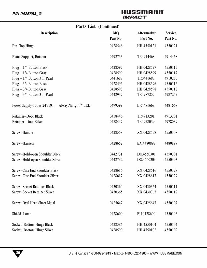
Pin–Top Hinge 0428546 HH.4550121 4550121
Plate, Support, Bottom 0492733 TP.4914468 4914468
Plug – 1/4 Button Black 0428597 HH.0428597 4550115
Plug – 1/4 Button Gray 0428599 HH.0428599 4550117
Plug – 1/4 Button 311 Pearl 0441687 TP.0441687 4910285
Plug – 3/4 Button Black 0428596 HH.0428596 4550116
Plug – 3/4 Button Gray 0428598 HH.0428598 4550118
Plug – 3/4 Button 311 Pearl 0442937 TP.4987257 4987257
Power Supply-100W 24VDC — Always*Bright™ LED 0499399 EP.4481668 4481668
Retainer–Door Black 0458446 TP.4913201 4913201
Retainer–Door Silver 0458447 TP.4978039 4978039
Screw–Handle 0428558 XX.0428558 4550108
Screw–Harness 0428652 BA.4480897 4480897
Screw–Hold-open Shoulder Black 0442731 DO.4550301 4550301
Screw–Hold-open Shoulder Silver 0442732 DO.4550303 4550303
Screw–Case End Shoulder Black 0428616 XX.0428616 4550128
Screw–Case End Shoulder Silver 0428617 XX.0428617 4550129
Screw–Socket Retainer Black 0430364 XX.0430364 4550111
Screw–Socket Retainer Silver 0430365 XX.0430365 4550112
Screw–Oval Head Sheet Metal 0425647 XX.0425647 4550107
Shield–Lamp 0428600 BU.0428600 4550106
Socket–Bottom Hinge Black 0428586 HH.4550104 4550104
Socket–Bottom Hinge Silver 0428590 HH.4550102 4550102
P/N 0425683_G®
30 U.S. & Canada 1-800-922-1919 • Mexico 1-800-522-1900 • WWW.HUSSMANN.COM
Parts List (Continued)
Description Mfg Aftermarket ServicePart No. Part No. Part No.
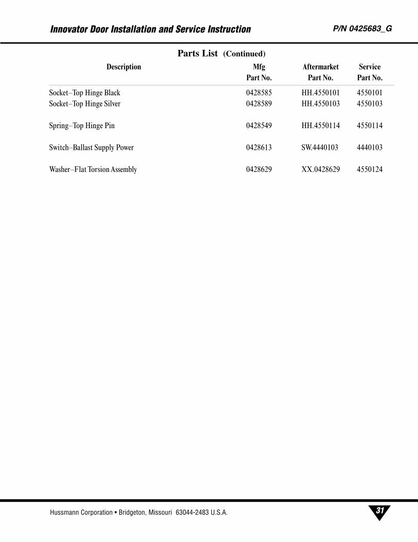
Socket–Top Hinge Black 0428585 HH.4550101 4550101
Socket–Top Hinge Silver 0428589 HH.4550103 4550103
Spring–Top Hinge Pin 0428549 HH.4550114 4550114
Switch–Ballast Supply Power 0428613 SW.4440103 4440103
Washer–Flat Torsion Assembly 0428629 XX.0428629 4550124
Innovator Door Installation and Service Instruction P/N 0425683_G
31Hussmann Corporation • Bridgeton, Missouri 63044-2483 U.S.A.
Parts List (Continued)
Description Mfg Aftermarket ServicePart No. Part No. Part No.

®
To obtain warranty information or other support, contact your
Hussmann representative.Please include the model and serial number of the product.
U.S. & Canada 1-800-922-1919 • Mexico 1-800-522-1900www.hussmann.com
Hussmann Corporation, Corporate Headquarters: Bridgeton, Missouri, U.S.A. 63044-2483 01 July 2008