ANALYSIS OF VIBRATION EFFECT ON FACTORY FOUNDATION IN …
8
44 ANALYSIS OF VIBRATION EFFECT ON FACTORY FOUNDATION IN A FLOUR MILL 1 Ohijeagbon, I. O 2 Olusegun, H. D,., 3 Adekunle, A. S., 4 Oladosu, O. A., 5 Bodunde, A. 1-4 Mechanical Engineering Department, University of Ilorin, P.M.B. 1515, Ilorin, Nigeria 5 National Centre for Agricultural Mechanization, P.M.B. 1525, Ilorin, Nigeria 2 Corresponding Author: Ohijeagbon, I. O. ABSTRACT Thirteen roller machines, in operation at a flour mill, all on one floor, were analyzed for spectra transmission and propagation, using a vibration analyzer. The vibration analyzer was placed at 8 different positions around each roller machine, generating unique spectra curves symbolic of signals transmitted. It was observered that with exponential characteristics above 2 in the polynomial equations resulted in significant signal propagation requiring isolation of the machines necessary. Results indicates that out of the 7 machines requiring isolation, cork would be needed for 3 with maximum displacement of 0.19 to 0.20mm, while composite pad would be needed for 4 with a maximum displacement of 0.10 to 0.16mm. The study had shown that vibration effects could be successfully monitored on factory floors through the vibration analyzer application, thus, minimizing harzardous effects on factory workers and facilties. Keywords: spectra transmission, vibration analyzer, signal propagation, isolation NOMENCLATURE Symbol Meaning Units CPE characteristic polynomial equation - SCC spectra characteristic curve - ec exponential characteristics - 1 m mass of vibrating factory floor kg 2 m mass of vibrating roller machine kg 3 m mass of vibrating analyzer kg 1 k spring constant relative to factory floor m kN 2 k spring constant relative to factory floor and vibrating roller machine m kN 3 k spring constant relative to roller machine and analyzer m kN 4 k spring constant relative to factory floor and analyzer m kN 1 c damping constant relative to factory floor m s kN 2 c damping constant relative to roller machine and analyzer m s kN 1 x displacement of 1 m m 2 x displacement of 2 m m 3 x displacement of 3 m m excitation frequency s rad n natural frequency s rad r T transmissibility - 1.0 Introduction Mechanical vibrations occur in all factories as long as there are operating machines. The machines and floor vibrate and may harmonize once their frequency approaches each other, or the natural frequency of one of the machines. Unwanted vibrations may be induced by large impulsive forces in machines such as hammers and presses; unbalanced reciprocating components such as engines, motors compressors, etc. (Kelly, LAUTECH Journal of Engineering and Technology 7(1) 2011: 44-51
Transcript of ANALYSIS OF VIBRATION EFFECT ON FACTORY FOUNDATION IN …

Ohijeagbon, I. O et. al./LAUTECH Journal of Engineering and Technology 7(1) 2011:44-51
44
ANALYSIS OF VIBRATION EFFECT ON FACTORY FOUNDATION
IN A FLOUR MILL
1Ohijeagbon, I. O
2Olusegun, H. D,.,
3Adekunle, A. S.,
4Oladosu, O. A.,
5Bodunde, A.
1-4 Mechanical Engineering Department, University of Ilorin, P.M.B. 1515, Ilorin, Nigeria
5 National Centre for Agricultural Mechanization, P.M.B. 1525, Ilorin, Nigeria
2Corresponding Author: Ohijeagbon, I. O.
ABSTRACT
Thirteen roller machines, in operation at a flour mill, all on one floor, were analyzed for spectra
transmission and propagation, using a vibration analyzer. The vibration analyzer was placed at 8 different
positions around each roller machine, generating unique spectra curves symbolic of signals transmitted. It
was observered that with exponential characteristics above 2 in the polynomial equations resulted in
significant signal propagation requiring isolation of the machines necessary. Results indicates that out of the
7 machines requiring isolation, cork would be needed for 3 with maximum displacement of 0.19 to 0.20mm,
while composite pad would be needed for 4 with a maximum displacement of 0.10 to 0.16mm. The study had
shown that vibration effects could be successfully monitored on factory floors through the vibration analyzer
application, thus, minimizing harzardous effects on factory workers and facilties.
Keywords: spectra transmission, vibration analyzer, signal propagation, isolation
NOMENCLATURE Symbol Meaning Units CPE characteristic polynomial equation -
SCC spectra characteristic curve -
ec exponential characteristics -
1m mass of vibrating factory floor kg
2m mass of vibrating roller machine kg
3m mass of vibrating analyzer kg
1k spring constant relative to factory floor m
kN
2k spring constant relative to factory floor and vibrating roller machine m
kN
3k spring constant relative to roller machine and analyzer m
kN
4k spring constant relative to factory floor and analyzer m
kN
1c damping constant relative to factory floor m
skN
2c damping constant relative to roller machine and analyzer m
skN
1x displacement of 1m m
2x displacement of 2m m
3x displacement of 3m m
excitation frequency srad
n natural frequency srad
rT transmissibility -
1.0 Introduction
Mechanical vibrations occur in all
factories as long as there are operating machines.
The machines and floor vibrate and may harmonize
once their frequency approaches each other, or the
natural frequency of one of the machines.
Unwanted vibrations may be induced by large
impulsive forces in machines such as hammers and
presses; unbalanced reciprocating components such
as engines, motors compressors, etc. (Kelly,
LAUTECH Journal of Engineering and Technology 7(1) 2011: 44-51

Ohijeagbon, I. O et. al./LAUTECH Journal of Engineering and Technology 7(1) 2011:44-51
45
2000).The dynamic forces produced by machinery
are often very large. However, the force transmitted
to the foundation or supporting structure can be
reduced by using flexible mountings with the
correct properties (Beards, 1999).
Ground vibrations arising from man-made
sources including construction activities, blasting,
vehicle and rail traffic may interfere with
surrounding residential and commercial activities
(Hiramatsu et al., 2006). Ground-borne vibrations
can also cause structural damage to nearby
buildings. The problems may occur as a result of
large vibration response, from repeated
occurrences of smaller amplitude vibrations, or
from differential settlement induced by particle
rearrangement. Ground-borne vibrations are often
accompanied by air-borne noise and other physical
disorders in the human body (Evans et al., 2005).
As a matter of fact, vibration has been proven to
result in musculoskeletal disorders of both the hand
and arm, the neck, and the back (Rasmussen,
2003).
Hiramatsu et al. (2006) suggested high
levels of vibrations can occur in floor systems due
to excitation from human activities such as walking
and aerobics. Excessive vibrations typically occur
in light weight floors, floor systems with low
stiffness, where the floor dominant natural
frequency is close to the excitation frequency, and
floors with low damping. While the floor mass and
stiffness are normally constant during the life of the
structure and can be estimated with a high degree
of accuracy, damping is more difficult to predict
because it is mostly associated with non-structural
components such as partitions, false floors,
suspended ceilings and ducts as well as furniture
such as filing cabinets and bookshelfs. Current
trends in the building industry associated with
using lightweight materials, long-span open-plan
floors and adoption of the electronic office, give
rise to the importance of understanding floor
vibrations and specifically damping. Sun et al.
(2007) gave a summary of factors affecting floor
vibrations, and discussed available damping
systems which can be used to reduce vibration
levels in floor systems.
In analyzing the vibration of a machine,
which is a complex mechanical system, it is useful
to consider the sources of vibration energy and the
paths in the machine that this energy takes.
Energy always moves, or flows, from the source of
the vibration to the energy absorber where it is
converted into heat. In some cases, this may be a
very short path, but in other situations, the energy
may travel relatively long distances before being
absorbed (Olusegun, 2004).
The most important absorber of energy in
a machine is friction, which can be sliding friction
or viscous friction. Sliding friction is represented
by relative motion between parts of the machine,
and viscous friction is known to occur in the oil
film in a journal bearing. If a machine has very
little friction, its vibration level tends to be fairly
high, for the vibration energy builds up due to the
lack of absorption. On the other hand, a machine
with greater inherent friction will have lower
vibration levels because the energy is absorbed
quickly (Ljunggren, 2006).
Mechanical vibrations are responsible for
machines not operating up to design standard,
especially if they are also affected by floor
vibration. The floor itself will now be capable of
transmitting response signals to the machines. The
vibration of the machine will begin to harmonize
with the transmitting vibration from the floor. Then
chatting occur which eventually leads to whirling
or resonance and serious damage to the moving
parts.
The work of Ljunggren (2006)
demonstrated the complexity of floor vibration,
both when it comes to reduction of vibration levels
as well as its cost. To change the vibration
properties of a floor, either the stiffness, the mass
or the damping must be changed. To change the
mass and/or the stiffness of an existing floor is not
easy since it requires major modifications which is
costly and unsafe.
This work is aimed at monitoring
microfloor vibrations in a newly-constructed
factory building which houses a variety of
machines with performances that are deleteriously
affected by floor vibrations. Mmeasurements of the
vibrations will profer appropriate ways to reduce
them at their sources.
2.0 Description of the Vibration Analyser
The locally designed and constructed
vibration analyzer consists of a microphone, a
preamplifier, a rectifier and a display meter as
shown in Figure 1.
Figure 1: Components of the vibration analyzer
Preamplifier
Microphone Displacement
signal Output Jack
Display
meter Rectifier Collector
Ohijeagbon, I. O et. al./LAUTECH Journal of Engineering and Technology 7(1) 2011:44-51
46
The vibration signals strike the diaphragm
of the microphone, causing the diaphragm to move
with the pressure fluctuations in the air. The
microphone converts these pressure fluctuations
into corresponding voltage fluctuations, which are
then amplified and conditioned for further analysis
by the preamplifier. In addition, at the microphone
all sound wave energy is converted into an
electrical signal that is boosted in magnitude at the
preamplifier. The amplified signal is then passed
through a collector which increase the signal. The
rectifier converts the electrical signal from
alternating current to direct current to cause the
digital display meter to register the oscillation in
millimetres.
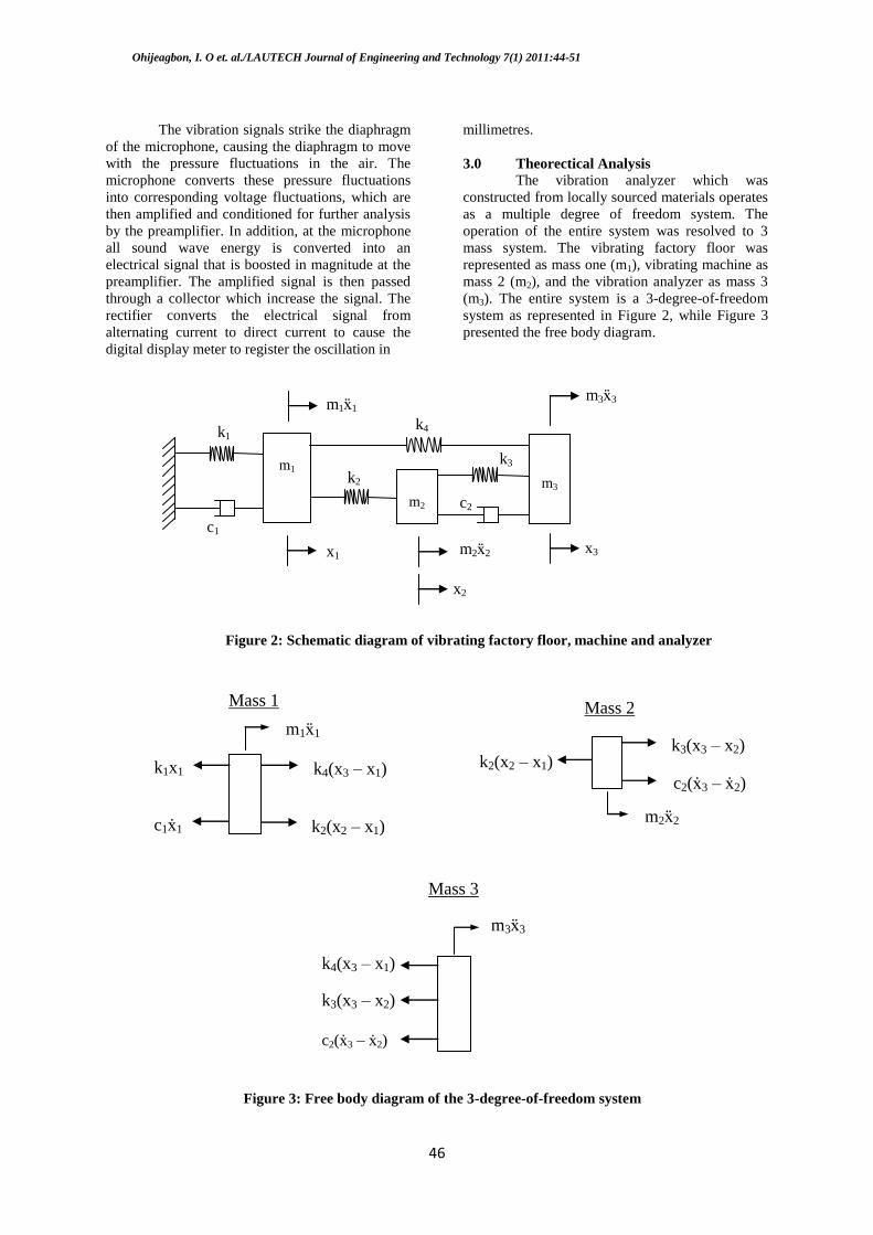
3.0 Theorectical Analysis
The vibration analyzer which was
constructed from locally sourced materials operates
as a multiple degree of freedom system. The
operation of the entire system was resolved to 3
mass system. The vibrating factory floor was
represented as mass one (m1), vibrating machine as
mass 2 (m2), and the vibration analyzer as mass 3
(m3). The entire system is a 3-degree-of-freedom
system as represented in Figure 2, while Figure 3
presented the free body diagram.
k4(x3 – x1)
k2(x2 – x1)
m1ẍ1
k1x1
c1ẋ1
Mass 1
c2(ẋ3 – ẋ2)
k2(x2 – x1) k3(x3 – x2)
m2ẍ2
Mass 2
m3ẍ3
k4(x3 – x1)
k3(x3 – x2)
c2(ẋ3 – ẋ2)
Mass 3
Figure 3: Free body diagram of the 3-degree-of-freedom system
x1
m1ẍ1
k1
c1
x2
m2ẍ2 x3
m3ẍ3
c2
k2
k3
k4
m1
m2
m3
Figure 2: Schematic diagram of vibrating factory floor, machine and analyzer

Ohijeagbon, I. O et. al./LAUTECH Journal of Engineering and Technology 7(1) 2011:44-51
47
The equations of motion are,
)1(1342214211111 xfxkxkxkkkxcxm
)2(2331223232222 xfxkxkxkkxxcxm
)3(3142334323233 xfxkxkxkkxxcxm
The matrix equation of motion is
)4(Fkxxcxm
which is expressed according to (eFundo Inc., 2009) as
)5(
)(
)(
)(
00
00
00
00
00
00
3
2
1
3
2
1
4334
3212
42421
2
2
1
3
2
1
3
2
1
tf
tf
tf
x
x
x
kkkk
kkkk
kkkkk
c
c
c
x
x
x
m
m
m
4.0 Methodology The dynamic force of the vibrating factory
floor was )(1 xf in equation (1) and was
responsible for the relative displacement of the
floor. Likewise )(2 xf and )(3 xf were the
dynamic forces of the Buhler roller machines and
the vibration analyzer and gave rise to the relative
displacement of the two respectively.
A locally designed vibration analyzer was
used to measure the vibrations of machines on the
factory floors to determine the oscillations on the
floors. Each reading was taken three times at eight
different machine positions shown on Figure 4. The
readings were taken at ten seconds intervals for
sixty seconds round the machines. The values of
time and displacement (oscillations) were used to
generate the spectra and characteristic polynomial
equations (CPE), which were used to determine the
possible positions of high floor response and
subsequent isolations. The readings were inputed
into a computer for spectra analysis and produced
the CPE shown in Appendix 1.
Damping is of prime importance in noise
and vibration control (Matter et al., 2009). The
magnitudes of response were used to determine the
type of isolator suitable for damping all abnormal
oscillations at the various positions on the floor.
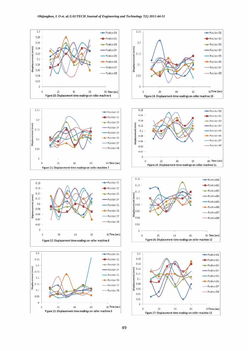
5.0 Result and Discussion
Figures 5 to 17 shows the displacement
and time readings recorded using the locally
constructed vibration analyzer. The readings were
for eight locations around the floor area of each of
the thirteen Buhler roller machines tested in a flour
mill. When the characteristic polynomial equations
(CPE) were of three exponential characteristics,
there was a tendency for the response to continue
rather than dampen.
The spectra characteristic curve (SCC) for
Roller Machine 1, Figure 5 was found to have
responded evenly with a maximum crest of
0.21mm at position D3 and a minimum trough of
0.08mm at Roller position D5. No damping was
recommended for Roller machine 1, as the CPE for
that system did not exceed 2 exponential
characteristics (ec). Roller Machines 3, 4, 6, 7 and
9 also had similar response to Roller Machine1 and
did not response beyond the 2ec signal. This was
because both internal response from machines as
well as external ones from surrounding machines
through the factory floor, did not affect the
machines significantly as indicated by the
amplitude of oscilation shown by the displacement-
time curves. The maximum displacements for
Roller Machines 3, 4, 6, 7 and 9 were 0.22, 0.22,
0.18, 0.21, and 0.23mm respectively. The minimum
displacements were 0.07, 0.06, 0.04, 0.05 and
0.04mm respectively.
Relatively, the SCC of Roller Machine 2,
Figure 6 was more pronounced than that of Roller
Machine 1, Figure 5. The CPE for Roller Machine
2 exceeded 2ec. There was a tendency for the SCC
to build up because of transfer of signal from other
machines through the factory floor. This
phenomena could lead to the growth of the signals
to a catastrophic level, a process known as
“chatting”. Roller Machines 5, 8, 10, 11, 12 and 13
exhibit similar behaviour as Roller Machine 2. The
SCC are shown on Figures 9, 12, 14, 15, 16 and 17
and to be pronounced.
Whereas Roller Machines 1, 3, 4, 6, 7 and
9 have no need for isolation, Roller Machines 2, 5,
Figure 4: Roller machine positions from where vibration
displacement were taken
D1
D2
D3 D4 D5
D6
D7 D8
BUHLER ROLLER
MACHINE

Ohijeagbon, I. O et. al./LAUTECH Journal of Engineering and Technology 7(1) 2011:44-51
48
8, 10, 11, 12 and 13 required isolation from the
factory floor through which their SCC were
propagated. The selection of isolators to match the
displacement in mm and the machine position at
which the isolator is to be placed are shown in
Table 1.
The condition for isolation for
conventional isolator design was considered in this
study, which required that the value of the
transmissibility Tt (the ratio of the force reaching
the floor compared to the force applied by the
machines) be greater than one (Tr>1) when
2n for the force transmitted to the floor
to be considered as large. When 1rT and
2n , the machine required no isolation.
6.0 Conclusion
The locally made vibration analyzer was
used to generate spectra characteristic curves at the
flour mill factory floor where Roller Machines
were mounted. The analysed SCC produced
characteristic polynomial equations. It was
observed that when the CPE was a regular 2
exponential characteristic signal, it was not
necessary to isolate the factory floor from the
machine vibrations, as the signals were not likely to
propagate significantly through the factory floor.
However, when the exponential characteristic
signal exceeded 2, the SCC tends to propagate as a
result of the influence of the signal from other
machines through the factory floor. Isolation of the
factory floor from the machine was done whenever
the CPE was a 3 exponential signal. Cork and
Composite pad were found to be adequate for the
isolation of the machines. The study had shown
that vibration effects could be successfully
monitored on factory floors through the vibration
analyzer application, thus, minimizing harzardous
effects on factory workers and facilties.
Ohijeagbon, I. O et. al./LAUTECH Journal of Engineering and Technology 7(1) 2011:44-51
49

Ohijeagbon, I. O et. al./LAUTECH Journal of Engineering and Technology 7(1) 2011:44-51
50
Table 1: Roller Machine Isolator Selected and
Position where fixed
Roller machine
number
Machine displacement
-Crest to
Trough (mm)
Isolator
selected
Factory floor Position where
Isolator was
placed
1 - None required -
2 0.19 cork D4
3 - None required - 4 - None required -
5 0.20 Cork D7
6 - None required - 7 - None required -
8 0.13 Composite pad D7
9 - None required - 10 0.19 Cork D1
11 0.11 Composite pad D7
12 0.10 Composite pad D3 13 0.16 Composite pad D5 & D8
7.0 Acknowledgement
The authors acknowledge Mr O. Shittu of
the Flour Mill where the test were done and the
crew that assisted in the experimentation. We also
acknowledge the workshop staff of the University
of Ilorin where our design of the vibration analyzer
was manufactured.
8.0 References
Beards, C. F. (1999), Engineering Vibration
Analysis with Application to Control
Systems, Edward Arnold, UK.
eFundo Inc. (2009), “3-Degree-of-freedom-
Vibratring System,” Oxford Instrument /
Industrial Analysis, PMI MASTER, PRI-
OES Analyzers for Metal Analysis,
Sunnyvale, CA 94088.
Evans, J.B. and Himmel, C.N. (2003), “Vibration
Mitigation Design for an Academic
Building Adjacent to a Turbine-Generator
Power Plant,” Proceedings of EuroNoise
2003 - the 5th
, European Conference on
Noise Control, Naples, European
Acoustics Association and Acoustical
Society of Italy.
Hiramatsu, K., Yokoshima, S., Ishibashi, T., &
Izumi, Y. (2006), “Measurement for the
Evaluation of the Habitability to Building
Vibration – Experimental Study Based on
the Measurement of Floor Vibrations
Caused by Human Activities,” AU Journal
of Technology and Design, Japan, Vol. 23,
pp197- 200.
Kelly, S. G. (2000), Fundamentals of Mechanical
Vibrations, Mc Graw Hill, Singapore.
Ljungren, F. (2006), “Floor Vibration: Dynamic
Properties and Subjective Perception”,
Department of Human Work Sciences,
Lulea University of Technology, Sweden.
Matter, M., Gmür, T., Cugnoni, J., &
Schorderet, A. (2009), “Numerical-
Experimental Identification of the Elastic
and Damping Properties in Composite
Plates,” Composite Structures Vol. 90,
pp180–187.
Olusegun, H.D. (2004), “Using the Response
Spectra Characteristics to Determine the
Suitability of Various Lubricants”, Journal
of Applied Science, Engineering and
Technology, Published by Faculty of
Technology, University of Ibadan,
Nigeria, Vol. 4(1), pp. 29-35.
Rasmussen, G. (2003) “Human Body Vibration
Exposure and its Measurement”, Journal
of Acoustical Society of America, Vol.
73(6), pp2229-2235.
Sun, H.L., Zhang, P.O., Chen, H.B., Zhang, K.,
& Gong, X.L. (2007), “Application of
Dynamic Vibration Absorbers in
Structural Vibration Control under Multi-
frequency Harmonic Excitations,” Journal
of Applied Acoustics, Vol. 69, pp1361-
1367.
APPENDIX 1
FLOOR VIBRATION EQUATIONS
Statements of Equations of the Machine Vibrations
transmitted
to the Foundations at the immediate Vicinity of the
Machines.
76.01674.00105.00003.0064082:
57.0144.00104.00003.0065083:
31.12498.00181.00006.0068085:
02.11834.00131.00004.0067084:
79.01499.00114.00004.0066084:
75.13803.0027.00009.0051088:
13.12472.0017.00005.0068084:
65.0176.00138.00005.0068085:
1
23458
23457
23456
23455
23454
23453
23452
23451
xxxxExEyD
xxxxExEyD
xxxxExEyD
xxxxExEyD
xxxxExEyD
xxxxExEyD
xxxxExEyD
xxxxExEyD
MachineRoller
48.01042.00066.00002.0063081:
3.00929.00068.00002.0063082:
17.00098.00019.0059062081:
03.11799.00128.00004.0067084:
89.14392.00343.00012.0052071:
29.00668.00044.00001.0062099:
71.01595.00111.00003.0065082:
94.26439.00476.00016.0052071:
2
2345
8
2345
7
2345
6
2345
5
2345
4
2345
3
2345
2
2345
1
xxxxExEyD
xxxxExEyD
xxxExExEyD
xxxxExEyD
xxxxExEyD
xxxxExEyD
xxxxExEyD
xxxxExEyD
MachineRoller

Ohijeagbon, I. O et. al./LAUTECH Journal of Engineering and Technology 7(1) 2011:44-51
51
93.01985.00127.00004.0065082:
09.12556.00187.00006.0069085:
4.12587.00182.00006.0068084:
36.12544.0018.00006.0069085:
33.00494.00037.00001.0062081:
81.14098.00305.0001.0052089:
33.12936.00209.00007.0051086:
17.1281.00213.00007.0051087:
3
2345
8
2345
7
2345
6
2345
5
2345
4
2345
3
2345
2
2345
1
xxxxExEyD
xxxxExEyD
xxxxExEyD
xxxxExEyD
xxxxExEyD
xxxxExEyD
xxxxExEyD
xxxxExEyD
MachineRoller
08.00027.00006.0055061098:
54.01425.00104.00003.0065082:
85.01469.00102.00003.0065082:
48.12843.00211.00007.0051086:
28.12497.00188.00006.0051086:
92.14194.00302.0001.0052089:
63.01537.00111.00004.0065083:
79.13915.00293.0001.0052089:
4
2345
8
2345
7
2345
6
2345
5
2345
4
2345
3
2345
2
2345
1
xxxExExEyD
xxxxExEyD
xxxxExEyD
xxxxExEyD
xxxxExEyD
xxxxExEyD
xxxxExEyD
xxxxExEyD
MachineRoller
34.00288.00012.0052072088:
61.25121.00354.00011.0052088:
55.01059.00083.00003.0065083:
48.01042.00066.00002.0053081:
02.12208.00158.00005.0068085:
51.13134.00237.00008.0051087:
45.00768.00052.00002.0062099:
51.13134.00237.00008.0051087:
5
2345
8
2345
7
2345
6
2345
5
2345
4
2345
3
2345
2
2345
1
xxxExExEyD
xxxxExEyD
xxxxExEyD
xxxxExEyD
xxxxExEyD
xxxxExEyD
xxxxExEyD
xxxxExEyD
MachineRoller
41.00875.00048.00001.0079092:
52.1363.00277.00009.0051088:
04.24046.00298.0001.0051088:
97.13904.0028.00009.0051088:
55.13255.00232.00008.0051087:
46.1293.00222.00007.0051086:
98.01972.00149.00005.0068084:
32.00483.00039.00001.0062081:
6
2345
8
2345
7
2345
6
2345
5
2345
4
2345
3
2345
2
2345
1
xxxxExEyD
xxxxExEyD
xxxxExEyD
xxxxExEyD
xxxxExEyD
xxxxExEyD
xxxxExEyD
xxxxExEyD
MachineRoller
15.00489.00041.00002.0063082:
66.13064.00203.00006.0068084:
85.01575.00116.00004.0066084:
38.00829.000052.00001.0062081:
07.12449.00182.00006.0051086:
65.13337.0025.00008.0051087:
96.13935.00292.0001.0051088:
39.12954.00231.00008.0051087:
7
2345
8
2345
7
2345
6
2345
5
2345
4
2345
3
2345
2
2345
1
xxxxExEyD
xxxxExEyD
xxxxExEyD
xxxxExEyD
xxxxExEyD
xxxxExEyD
xxxxExEyD
xxxxExEyD
MachineRoller
68.13418.00232.00007.0051086:
25.36512.00469.00015.0052071:
86.13644.00267.00009.0051088:
24.2432.00305.0001.0051088:
46.13154.00224.00007.0051086:
07.0005.00007.0054079097:
14.00546.00045.00002.0063081:
58.01033.00075.00002.0063082:
8
2345
8
2345
7
2345
6
2345
5
2345
4
2345
3
2345
2
2345
1
xxxxExEyD
xxxxExEyD
xxxxExEyD
xxxxExEyD
xxxxExEyD
xxxExExEyD
xxxxExEyD
xxxxExEyD
MachineRoller
55.25301.00363.00011.0052089:
73.01664.00116.00004.0065083:
62.25512.00409.00013.0052071:
01.00274.00032.00001.0063082:
36.00879.00064.00002.0063082:
7.01145.00078.00002.0064082:
7.01145.00078.00002.0064082:
29.1287.00201.00006.0069085:
9
2345
8
2345
7
2345
6
2345
5
2345
4
2345
3
2345
2
2345
1
xxxxExEyD
xxxxExEyD
xxxxExEyD
xxxxExEyD
xxxxExEyD
xxxxExEyD
xxxxExEyD
xxxxExEyD
MachineRoller
11.1217.00165.00006.0069085:
76.13797.00267.00008.0051086:
65.13302.00241.00008.0051087:
19.00493.00027.0056074197:
19.00391.00044.00002.0063082:
29.00563.00046.00002.0063082:
01.1189.00132.00004.0066083:
73.13668.00246.00007.0051086:
10
2345
8
2345
7
2345
6
2345
5
2345
4
2345
3
2345
2
2345
1
xxxxExEyD
xxxxExEyD
xxxxExEyD
xxxExExEyD
xxxxExEyD
xxxxExEyD
xxxxExEyD
xxxxExEyD
MachineRoller
8.01511.00117.00004.0066083:
36.00248.00003.0058062082:
99.02289.00168.00006.0069085:
58.13121.00232.00008.0051086:
54.00825.0005.00001.0062097:
91.01668.00121.00004.0066083:
03.00317.00028.00001.0062081:
02.00004.0001.0055079095:
11
2345
8
2345
7
2345
6
2345
5
2345
4
2345
3
2345
2
2345
1
xxxxExEyD
xxxExExEyD
xxxxExEyD
xxxxExEyD
xxxxExEyD
xxxxExEyD
xxxxExEyD
xxxExExEyD
MachineRoller
48.01308.00104.00004.0066083:
57.01236.00082.00002.0063082:
1110141.00012.0055061097:
15.00373.00019.0054074108:
24.00328.00023.0057061096:
92.01666.00118.00004.0066083:
42.01154.00089.00003.0065083:
7.0171.0012.00004.0065083:
12
2345
8
2345
7
2345
6
2345
5
2345
4
2345
3
2345
2
2345
1
xxxxExEyD
xxxxExEyD
ExxxExExEyD
xxxExExEyD
xxxExExEyD
xxxxExEyD
xxxxExEyD
xxxxExEyD
MachineRoller
76.13543.00269.00009.0051088:
27.00128.00005.0056062081:
22.0013.00004.0065073093:
13.12208.00164.00005.0068084:
14.00123.00031.00002.0063082:
44.00805.00067.00002.0064082:
41.0061.00037.0059079092:
67.01326.00092.00003.0064082:
13
2345
8
2345
7
2345
6
2345
5
2345
4
2345
3
2345
2
2345
1
xxxxExEyD
xxxExExEyD
xxxExExEyD
xxxxExEyD
xxxxExEyD
xxxxExEyD
xxxExExEyD
xxxxExEyD
MachineRoller