Analysis of simply supported aluminum and composite plates with uniform loading to determine...
25
Analysis of Simply Supported Aluminum and Composite Plates with Uniform Loading to Determine Equivalent Plate Ply Stack-Up by Kenneth Carroll An Engineering Project Submitted to the Graduate Faculty of Rensselaer Polytechnic Institute In Partial Fulfillment of the Requirements for the degree of MASTER OF ENGINEERING IN MECHANICAL ENGINEERING Approved: ________________________________________________ Ernesto Gutierrez-Miravete, Engineering Project Advisor Rensselaer Polytechnic Institute Hartford, Connecticut December 2013
Transcript of Analysis of simply supported aluminum and composite plates with uniform loading to determine...
Analysis of Simply Supported Aluminum and Composite Plates with Uniform Loading to
Determine Equivalent Plate Ply Stack-Up
by
Kenneth Carroll
An Engineering Project Submitted to the
Graduate Faculty of Rensselaer Polytechnic Institute
In Partial Fulfillment of the
Requirements for the degree of
MASTER OF ENGINEERING IN MECHANICAL ENGINEERING
Approved:
________________________________________________
Ernesto Gutierrez-Miravete, Engineering Project Advisor
Rensselaer Polytechnic Institute
Hartford, Connecticut
December 2013

CONTENTS
List of Tables............................................................................................................
List of Figures..........................................................................................................
List of Symbols.........................................................................................................
Acknowledgement....................................................................................................
Abstract....................................................................................................................
Introduction...............................................................................................................
Methodology.............................................................................................................
Aluminum Plate Analysis...............................................................................
Thin Plate Theory................................................................................
Material Properties..............................................................................
Equation for Thin Plate Theory..........................................................
Composite Plate Analysis.............................................................................
Composite Thin Plate Theory............................................................
Material Properties of Composite Material........................................
Equations for Composite Thin Plate Theory.....................................
Maximum Stress Failure Criterion.....................................................
Tsai-Wu Failure Criterion..................................................................
Plate Model...................................................................................................
ANSYS Model for Aluminum Plate.....................................................
ANSYS Model for Composite Plate....................................................
Results.....................................................................................................................
Aluminum Plate.............................................................................................
Composite Plate...........................................................................................

Composite Failure Criterion Results............................................................
ANSYS Results - Aluminum Plate................................................................
ANSYS Results - Composite Plate...............................................................
Error Analysis...............................................................................................
Conclusion...............................................................................................................
References..............................................................................................................
Appendix A: Thin Plate Theory Analysis................................................................
Appendix B: Table from Thin Plate Theory by Timoshenko...................................
Appendix C: Composite Thin Plate Theory.............................................................
Appendix D: ANSYS Code for Aluminum Plate.......................................................
Appendix E: ANSYS Code for Composite Plate......................................................

LIST OF TABLES
Table 1: Material Properties of Aluminum

LIST OF FIGURES
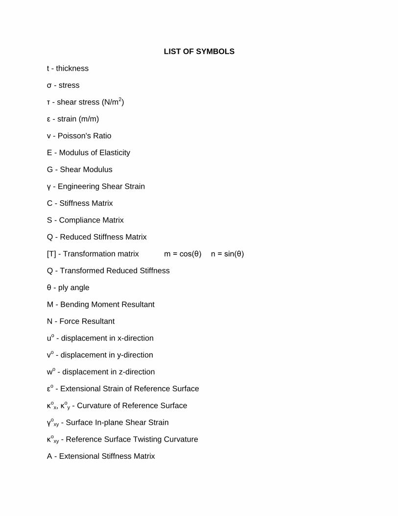
LIST OF SYMBOLS
t - thickness
σ - stress
τ - shear stress (N/m2)
ε - strain (m/m)
ν - Poisson's Ratio
E - Modulus of Elasticity
G - Shear Modulus
γ - Engineering Shear Strain
C - Stiffness Matrix
S - Compliance Matrix
Q - Reduced Stiffness Matrix
[T] - Transformation matrix m = cos(θ) n = sin(θ)
Q - Transformed Reduced Stiffness
θ - ply angle
M - Bending Moment Resultant
N - Force Resultant
uo - displacement in x-direction
vo - displacement in y-direction
wo - displacement in z-direction
εo - Extensional Strain of Reference Surface
κox, κ
oy - Curvature of Reference Surface
γoxy - Surface In-plane Shear Strain
κoxy - Reference Surface Twisting Curvature
A - Extensional Stiffness Matrix
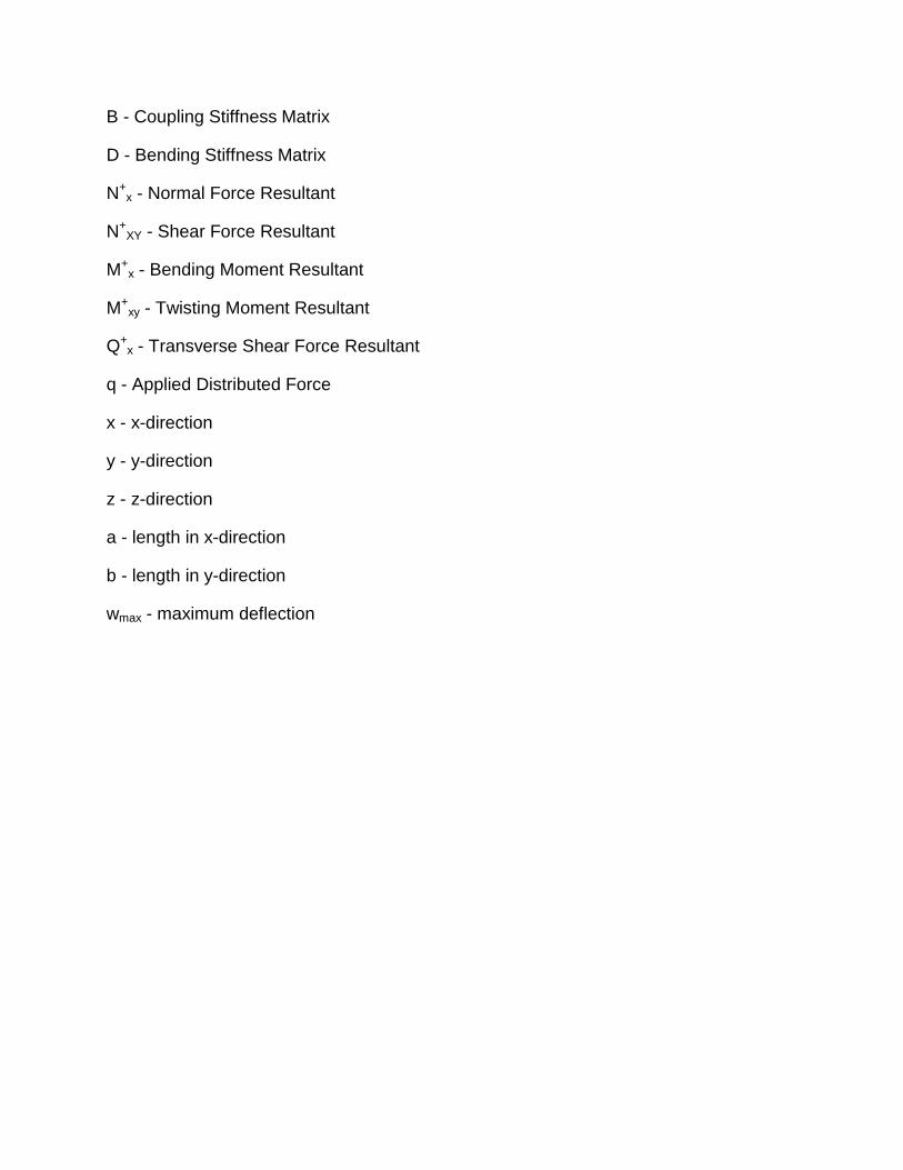
B - Coupling Stiffness Matrix
D - Bending Stiffness Matrix
N+x - Normal Force Resultant
N+XY - Shear Force Resultant
M+x - Bending Moment Resultant
M+xy - Twisting Moment Resultant
Q+x - Transverse Shear Force Resultant
q - Applied Distributed Force
x - x-direction
y - y-direction
z - z-direction
a - length in x-direction
b - length in y-direction
wmax - maximum deflection

ACKNOWLEDGMENT

ABSTRACT

INTRODUCTION
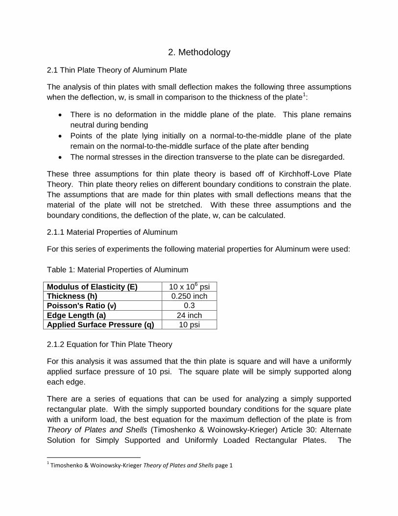
2. Methodology
2.1 Thin Plate Theory of Aluminum Plate
The analysis of thin plates with small deflection makes the following three assumptions
when the deflection, w, is small in comparison to the thickness of the plate1:
There is no deformation in the middle plane of the plate. This plane remains
neutral during bending
Points of the plate lying initially on a normal-to-the-middle plane of the plate
remain on the normal-to-the-middle surface of the plate after bending
The normal stresses in the direction transverse to the plate can be disregarded.
These three assumptions for thin plate theory is based off of Kirchhoff-Love Plate
Theory. Thin plate theory relies on different boundary conditions to constrain the plate.
The assumptions that are made for thin plates with small deflections means that the
material of the plate will not be stretched. With these three assumptions and the
boundary conditions, the deflection of the plate, w, can be calculated.
2.1.1 Material Properties of Aluminum
For this series of experiments the following material properties for Aluminum were used:
Table 1: Material Properties of Aluminum
Modulus of Elasticity (E) 10 x 106 psi
Thickness (h) 0.250 inch
Poisson's Ratio (ν) 0.3
Edge Length (a) 24 inch
Applied Surface Pressure (q) 10 psi
2.1.2 Equation for Thin Plate Theory
For this analysis it was assumed that the thin plate is square and will have a uniformly
applied surface pressure of 10 psi. The square plate will be simply supported along
each edge.
There are a series of equations that can be used for analyzing a simply supported
rectangular plate. With the simply supported boundary conditions for the square plate
with a uniform load, the best equation for the maximum deflection of the plate is from
Theory of Plates and Shells (Timoshenko & Woinowsky-Krieger) Article 30: Alternate
Solution for Simply Supported and Uniformly Loaded Rectangular Plates. The
1 Timoshenko & Woinowsky-Krieger Theory of Plates and Shells page 1
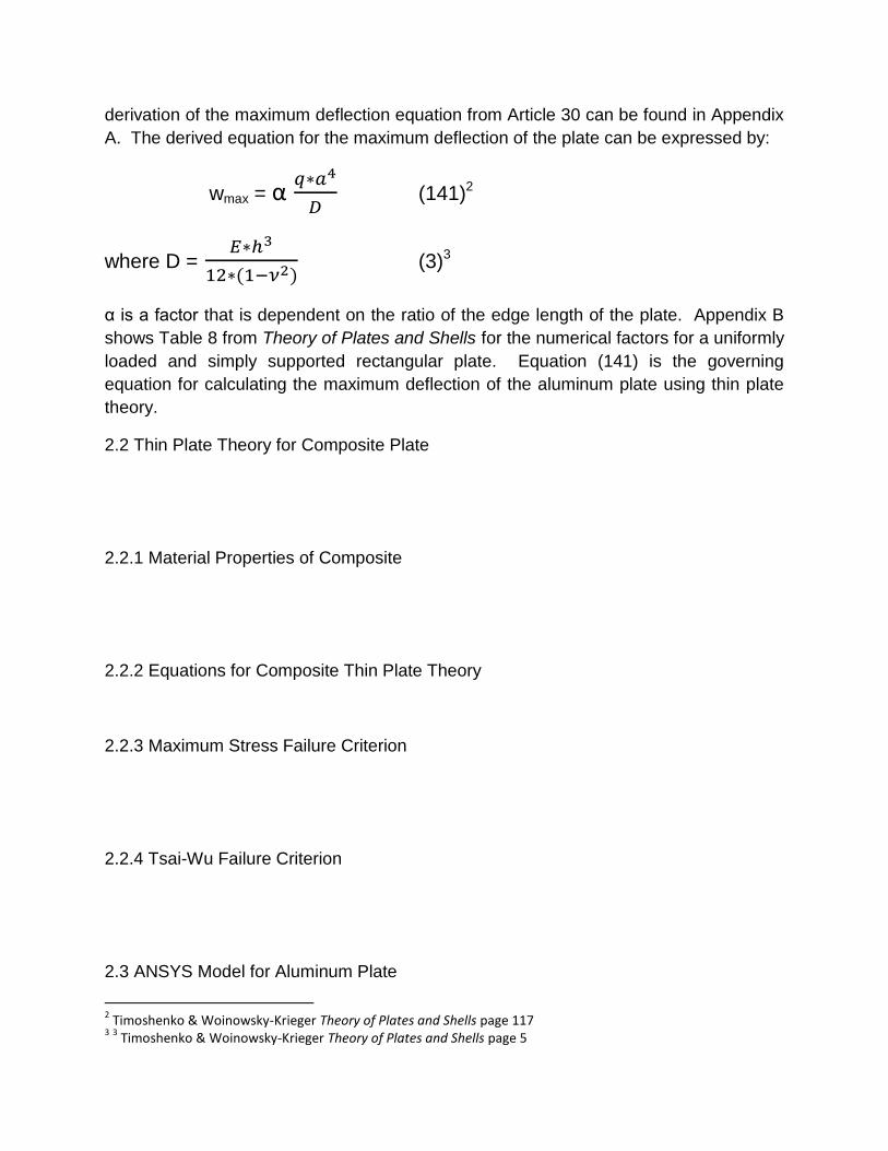
derivation of the maximum deflection equation from Article 30 can be found in Appendix
A. The derived equation for the maximum deflection of the plate can be expressed by:
wmax = α
(141)2
where D =
(3)3
α is a factor that is dependent on the ratio of the edge length of the plate. Appendix B
shows Table 8 from Theory of Plates and Shells for the numerical factors for a uniformly
loaded and simply supported rectangular plate. Equation (141) is the governing
equation for calculating the maximum deflection of the aluminum plate using thin plate
theory.
2.2 Thin Plate Theory for Composite Plate
2.2.1 Material Properties of Composite
2.2.2 Equations for Composite Thin Plate Theory
2.2.3 Maximum Stress Failure Criterion
2.2.4 Tsai-Wu Failure Criterion
2.3 ANSYS Model for Aluminum Plate
2 Timoshenko & Woinowsky-Krieger Theory of Plates and Shells page 117
3 3 Timoshenko & Woinowsky-Krieger Theory of Plates and Shells page 5

The aluminum plate was modeled in ANSYS using a SHELL63 element. The SHELL63
element was used for the aluminum plate analysis because the element has both
bending and membrane capabilities and is used for a linear elastic analysis. Each node
of the element has six degrees of freedom, three translational degrees of freedom and
three rotational degrees of freedom.
The SHELL63 element was used to create an area by dimensions in the active
workspace. Due to the symmetry of the aluminum plate, only a quarter of the plate has
to be created for the analysis. The 12 inch square was oriented in the x-y plane. A
thickness of 0.250 inch was entered for the plate in the z-direction. The edge length for
the generate mesh was 0.75 inch. Figure 1 below shows the generated plate in ANSYS
with meshing.
Figure 1: SHELL63 Element with Mesh (Edge Length = 0.75")
The aluminum plate had a series of boundary conditions applied in order to measure the
maximum deflection. The keypoint at the origin of the active workspace is where the
maximum deflection should be measured. Side 1 is constrained in the Uz direction to
prevent translation in the z-direction and in ROTy to prevent rotation in the y-direction.
Side 2 is constrained in the Uz direction to prevent translation in the z-direction and in
ROTx to prevent rotation in the x-direction. Side 3 is constrained in ROTx to prevent
rotation in the x-direction. Side 4 is constrained in ROTy to prevent rotation in the y-
direction. The keypoint at the origin is constrained in Ux and Uy directions. These
boundary conditions create the simply supported edges along Side 1 and Side 2. The
sides are prevented from freely rotating in both the x- and y-directions. Figure 2 shows
Side 1
Side 2
Side 3
Side 4
Origin
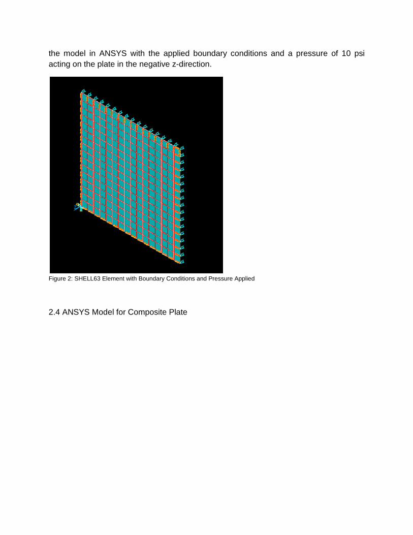
the model in ANSYS with the applied boundary conditions and a pressure of 10 psi
acting on the plate in the negative z-direction.
Figure 2: SHELL63 Element with Boundary Conditions and Pressure Applied
2.4 ANSYS Model for Composite Plate
3. Results
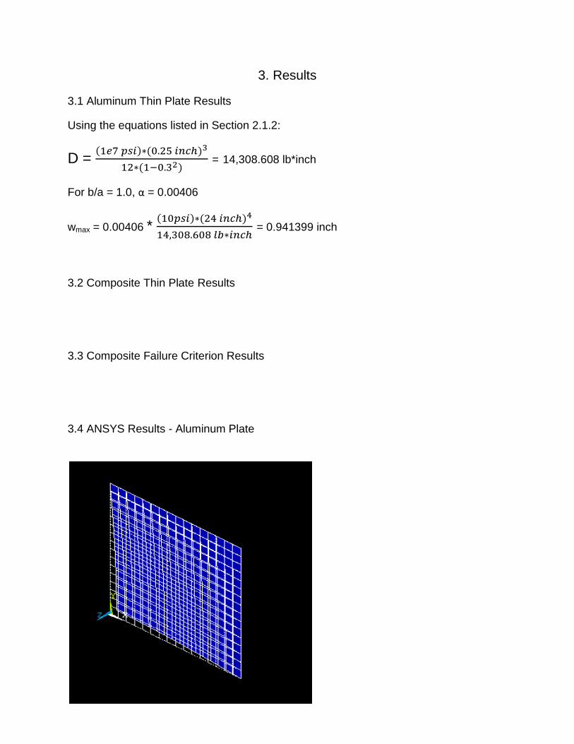
3.1 Aluminum Thin Plate Results
Using the equations listed in Section 2.1.2:
D =
= 14,308.608 lb*inch
For b/a = 1.0, α = 0.00406
wmax = 0.00406 *
= 0.941399 inch
3.2 Composite Thin Plate Results
3.3 Composite Failure Criterion Results
3.4 ANSYS Results - Aluminum Plate

Figure 3: Aluminum Plate Deformed + Undeformed
Deflection in negative z-direction = 0.941085"
Figure 4&5: Aluminum Plate Nodal Solution - Z-Component of Displacement
3.5 ANSYS Results - Composite Plate
3.6 Error Analysis
The maximum deflection using ANSYS to analyze the simply supported aluminum plate
is 0.941085". The maximum deflection using the governing equations for the simply
supported aluminum plate is 0.941399".
% Error =
* 100

% Error = -
* 100 = 0.0334%

4. Conclusions
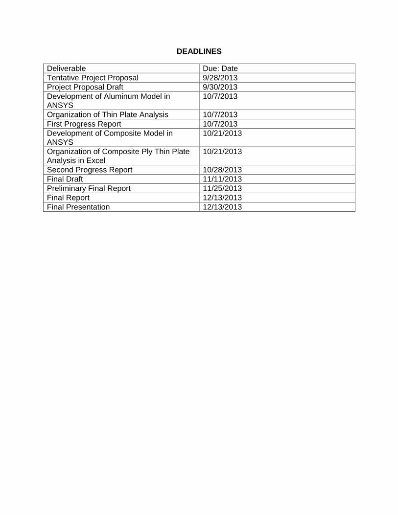
DEADLINES
Deliverable Due: Date
Tentative Project Proposal 9/28/2013
Project Proposal Draft 9/30/2013
Development of Aluminum Model in ANSYS
10/7/2013
Organization of Thin Plate Analysis 10/7/2013
First Progress Report 10/7/2013
Development of Composite Model in ANSYS
10/21/2013
Organization of Composite Ply Thin Plate Analysis in Excel
10/21/2013
Second Progress Report 10/28/2013
Final Draft 11/11/2013
Preliminary Final Report 11/25/2013
Final Report 12/13/2013
Final Presentation 12/13/2013

REFERENCES
1. Hyer, Michael W. Stress Analysis of Fiber-Reinforced Composite Materials
Update Edition, 2009
2. Timoshenko, S. and Woinowsky-Krieger, S. Theory of Plates and Shells
2nd Edition, 1959
3. Notes from MANE 6180 Mechanics of Composite Materials R. Naik 2013
4. Manahan, Mer Arnel A Finitie Element Study of the Deflection of Simply Supported
Composite Plates Subject to Uniform Load. RPI Hartford Master's Project December
2011
5. Kirchoff-Love Plate Theory Wikipedia
http://en.wikipedia.org/wiki/Kirchhoff%E2%80%93Love_plate_theory

APPENDIX A

APPENDIX B
Timoshenko & Woinowsky-Krieger Theory of Plates and Shells page 120

APPENDIX C

APPENDIX D

APPENDIX E