Analysis of horizontal bearing capacity of a single pile · Analysis of horizontal bearing capacity...
12
Engineering manual No. 16 Updated: 02/2018 1 Analysis of horizontal bearing capacity of a single pile Program: Pile Soubor: Demo_manual_16.gpi The objective of this engineering manual is to explain the usage of the GEO 5 – PILE program for the analysis of horizontal bearing capacity of a single pile. Problem specification The general specification of the problem is described in the previous chapter (12. Pile foundations – Introduction). Carry out all calculations for the horizontal bearing capacity of a single pile as a follow-up to the previous problem presented in chapter 13. Analysis of vertical load-bearing capacity of a single pile. The resultant of loading components 1 , 1 , 1 , , x y H M N acts at the pile head level. Calculate pile dimensions in accordance with EN 1992-1. Problem specification chart – single pile Solution We will use the GEO 5 – PILES program to analyse this problem. In the text below we will describe the solution of this problem step by step.
Transcript of Analysis of horizontal bearing capacity of a single pile · Analysis of horizontal bearing capacity...

Engineering manual No. 16
Updated: 02/2018
1
Analysis of horizontal bearing capacity of a single pile
Program: Pile
Soubor: Demo_manual_16.gpi
The objective of this engineering manual is to explain the usage of the GEO 5 – PILE program
for the analysis of horizontal bearing capacity of a single pile.
Problem specification
The general specification of the problem is described in the previous chapter (12. Pile foundations
– Introduction). Carry out all calculations for the horizontal bearing capacity of a single pile as a
follow-up to the previous problem presented in chapter 13. Analysis of vertical load-bearing capacity
of a single pile. The resultant of loading components 1,1,1 ,, xy HMN acts at the pile head level.
Calculate pile dimensions in accordance with EN 1992-1.
Problem specification chart – single pile
Solution
We will use the GEO 5 – PILES program to analyse this problem. In the text below we will describe
the solution of this problem step by step.
2
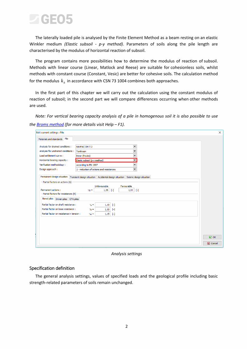
The laterally loaded pile is analysed by the Finite Element Method as a beam resting on an elastic
Winkler medium (Elastic subsoil - p-y method). Parameters of soils along the pile length are
characterised by the modulus of horizontal reaction of subsoil.
The program contains more possibilities how to determine the modulus of reaction of subsoil.
Methods with linear course (Linear, Matlock and Reese) are suitable for cohesionless soils, whilst
methods with constant course (Constant, Vesic) are better for cohesive soils. The calculation method
for the modulus hk in accordance with CSN 73 1004 combines both approaches.
In the first part of this chapter we will carry out the calculation using the constant modulus of
reaction of subsoil; in the second part we will compare differences occurring when other methods
are used.
Note: For vertical bearing capacity analysis of a pile in homogenous soil it is also possible to use
the Broms method (for more details visit Help – F1).
Analysis settings
Specification definition
The general analysis settings, values of specified loads and the geological profile including basic
strength-related parameters of soils remain unchanged.

3
Fisrtly, it is necessary to uncheck the option “Do not calculate horizontal bearing capacity” in the
frame “Settings”.
“Settings” frame
We will choose the “constant” modulus in the „Modulus hk “ frame.
“Modulus hk ” frame
Note: The constant course of the modulus of horizontal reaction of subsoil depends
on the modulus of deformation of soil MPaEdef and the reduced pile width mr
(for more details visit Help – F1).
Subsequently, in the parameters of soils, we will set the value of the angle of dispersion
within the range ef
ef
4. This coefficient is, therefore, determined relative to the internal soil
friction angle (for more details visit Help – F1).

4
Soil
(Soil classification)
Unit weight
3mkN
Angle of internal
friction ef
Angle of dispersion
Type
of soil
CS – Sandy clay, firm consistency
18,5 24,5 10,0 Cohesive
S-F – Sand with trace of fines, medium dense soil
17,5 29,5 15,0 Cohesionless
Table with the soil parameters – Horizontal bearing capacity of single pile
Now we will move on to the “Horizontal capacity” frame, where we determine the value of the
maximum horizontal deformation at the pile head, the course of the internal forces along the pile
length and results of the pile dimensioning for the assessment of concrete reinforcement in the
direction of the maximum effect.
“Horizontal bearing capacity” frame – Assessment for constant course of modulus hk

5
Note: The boundary condition for a pile fixing at the pile base is modelled first in the cases of end-
bearing piles with bases in hard rock or semi-rock sub-grade (it is not this case). The boundary
conditions at pile head are applied when the so-called deformation load is used, where only the
angular rotation and deformation at pile head are set in the program, without setting the force load
(for more details visit Help – F1).
In this frame we will also carry out the dimensioning of pile reinforcement. We will design a
longitudinal structural reinforcement – 18 pcs Ø 16 mm and a minimum concrete cover of 60 mm,
corresponding to the environmental exposure grade XC1.
Horizontal bearing capacity” frame – dimensioning

6
In this case we consider the reinforcement ratio for the laterally loaded single pile in accordance
with CSN EN 1536: Execution of special geotechnical works - Bored piles (Table 4 – Minimum
reinforcement of bored piles). This possibility is set in the program as the “Pile”.
Cross-sectional area of the pile:
2mAc
Area of longitudinal reinforcement:
2mAs
25.0 mAc cs AA %5.0
22 0.15.0 mAm c 20025.0 mAs
20.1 mAc cs AA %25.0
“EN 1536: Table 4 – Minimum reinforcement of bored piles“
Note: It is better for compressed elements to use the reinforcement ratio as if were for a ”column”,
whilst a “beam” is better for piles subjected to bending. For a combination of vertical and lateral
loading the CSN EN 1536 prescribes the minimum reinforcement ratio for bored piles corresponding
to the proportion of the reinforcement sectional area to the concrete area (for more details visit Help
– F1).
We observe the use of the bending-subjected pile cross-section and the condition for the
minimum reinforcement ratio in the pile dimensioning results.
Dialogue Window – “Verification (detailed)“
Analysis results
Within the framework of the assessment of the laterally loaded single pile, we are interested in
the courses of internal forces along the pile length, the maximum deformations and the use of the
pile cross-section. For a constant course of the modulus of horizontal reaction of subsoil hk the
resultant values are as follows:

7
Maximum pile deformation: mmu 2.4max .
Maximum shear force: kNQ 0.85max .
Maximum bending moment: kNmM 0.120max .
RC pile bearing capacity (flexure + pressure): 16,3 %
SATISFACTORY
RC pile bearing capacity (shear): 20,2 %
SATISFACTORY
Pile reinforcement ratio: 69,1 %
SATISFACTORY
Comparison of results of various methods of the determination of the modulus of subsoil
reaction
The values and course of the modulus of horizontal reaction of subsoil hk vary depending on the
analysis methods used and input soil parameters, which affect it:
CONSTANT: angle of dispersion ,
LINEAR (Bowles): angle of dispersion ,
coefficient 3mMNk according to the soil type,
According to CSN 73 1004: cohesive, or cohesionless soil,
modulus of horizontal compressibility 3mMNnh ,
According to VESIC: modulus of elasticity MPaE .

8
In this calculation, we will input values in the program using Help (see F1) as follows:
Modulus of subsoil
reaction 3mMNkh
Angle of dispersion
Coefficient
3mMNk
Modulus of elasticity
MPaE
Modulus of horizontal compressibility
3mMNnh
CONSTANT 10 – CS
--- --- --- 15 – S-F
LINEAR (Bowles) 10 – CS 60 – CS
--- --- 15 – S-F 150 – S-F
CSN 73 1004 Cohesive soil – CS, firm consistency ---
Cohesionless soil – S-F, medium dense 4,5
VESIC --- --- 5,0 – CS
--- 15,5 – S-F
Summary table of soil parameters for horizontal bearing capacity of single pile
Now we will get back to the input data settings; we will always change the respective method of
the calculation of the modulus of horizontal reaction of subsoil and then we will add the remaining
parameters of soils. We will carry out the procedure for the following methods:
using the linear course (according to Bowles),
according to CSN 73 1004,
according to Vesic.

9
Linear course of the modulus of horizontal reaction of subsoil hk , deformation and internal forces

10
Course of modulus of subsoil reaction hk according to CSN 73 1004, deformation and internal
forces

11
Course of modulus of horizontal reaction of subsoil hk according to Vesic, deformation and
internal forces
Results of the analysis of horizontal bearing capacity of single pile:
The results of the analysis of horizontal bearing capacity of a single pile relative to the method
used for the calculation of the modulus of horizontal reaction of subsoil hk are presented in the
following table:
Modulus of subsoil
reaction 3mMNkh
Max. pile displacement
mmumax
Max. bending moment
kNmM max
RC pile bearing capacity
%
CONSTANT 4.2 120.0 16.3
LINEAR (Bowles) 6.4 174.44 18.2
CSN 73 1004 5.6 149.87 17.3
VESIC 9.3 120.0 16.3
Summary of results – Horizontal bearing capacity and dimensioning of single pile

12
Conclusion
From the calculation results, it follows that the observed values of internal forces along the pile
length and the maximum deformations at the pile head are slightly different, but the influence of the
chosen method of the modulus of subsoil reaction calculation is not crucial.