Masonry Enclosure Walls: Lessons learnt from the recent Abruzzo Earthquake

Ana
alysis a
NATION
and DM
In Parti
DEPARNAL INST
esign Masonr
A Projial Fulfillm
For th
BachelorIn Civi
Amrap10
Swarna P10
RTMENT OTITUTE O
i
of Earry Bui
ect Submitment of the he Degree
r of Technil Engineer
By
pali Bhowm0401003
& Prava Mo0401026
OF CIVIL EOF TECH
2008
rthquilding
tted Requiremof
nology ring
mik
hanty
NGINEERINOLOGY
ake R
ments
ING Y ROURK
Resista
KELA
ant

Ana
alysis a
NATION
and DM
In Parti
DEPARNAL INST
esign Masonr
A Projial Fulfillm
For th
BachelorIn Civi
Amrap10
Swarna P10
Under thProf.M
RTMENT OTITUTE O
ii
of Earry Bui
ect Submitment of the he Degree
r of Technil Engineer
By
pali Bhowm0401003
& Prava Mo0401026
he Guidanrs. Asha P
OF CIVIL EOF TECH
2008
rthquilding
tted Requiremof
nology ring
mik
hanty
nce of Patel
NGINEERINOLOGY
ake R
ments
ING Y ROURK
Resista
KELA
ant

i
NATIONAL INSTITUTE OF TECHNOLOGY ROURKELA
CERTIFICATE This is to certify that the project entitled “ANALYSIS AND DESIGN OF EARTHQUAKE
RESITANT MASONRY BUILDINGS” submitted by Miss Amrapali Bhowmik [Roll no.
10401003] and Miss Swarna Prava Mohanty [Roll no. 10401026] in partial fulfillment of the
requirements for the award of bachelor of technology degree in Civil engineering at the National
Institute of Technology Rourkela (deemed University) is an authentic work carried out by them
under my supervision and guidance.
To the best of my knowledge the matter embodied in the project has not been submitted to any
other university/institute for the award of any degree or diploma.
Date: 09-05-2008 Prof. Mrs Asha Patel
Department of Civil Engineering National Institute of Technology Rourkela - 769008

ii
ACKNOWLEDGEMENT We would like to express our profound sense of deepest gratitude to our guide and motivator
Prof. Asha Patel, professor, Civil Engineering Department, National Institute of Technology,
Rourkela for her valuable guidance, sympathy and co-operation for providing necessary facilities
and sources during the entire period of this project.
We wish to convey our sincere gratitude to all the faculties of Civil Engineering Department who
have enlightened us during our studies. The facilities and co-operation received from the
technical staff of Civil Engineering Department is thankfully acknowledged.
We express our thanks to all those who helped us one way or other.
Last, but not the least, we would like to thank the authors of various research articles and books
that we referred to.
Amrapali Bhowmik Swarna Prava Mohanty Roll No. 10401003 Roll No. 10401026 B.Tech 8th Semester B. Tech 8th Semester

iii
CONTENTS Chapter No. Title Page No. CERTIFICATE i
ACKNOWLEDGEMENT ii
CONTENTS iii
LIST OF FIGURES iv
LIST OF TABLES v
ABSTRACT x
1 INTRODUCTION 1
1.1 OBJECTIVE OF PROJECT 1
1.2 LESSONS LEARNT FROM 2
PAST EARHQUAKE
1.3 FAILURE MODES OF MASONRY 4
1.4 BASIC GUIDELINES OF 7 MASONRY BUILDING
2 BASIC STEPS FOR ANALYIS 21 AND DESIGN OF MASONRY BUILDING
2.1 DETERMINATION OF DESIGN 22 EARTHQUAKE FORCES
2.2 DETERMINATION OF WALL RIGIDITY 28 2.3 DETERMINATION OF TORSIONAL FORCES 33 2.4 DETERMINATION INCREASE IN 36 AXIAL LOAD DUE TO OVERTURNING 2.5 DETERMINATION OF PIER LOADS, 39 MOMENTS AND SHEAR
iv
Chapter No. Title Page No.
2.6 DESIGN OF SHEAR WALLS FOR 40 AXIAL LOAD AND MOMENTS 2.7 DESIGN OF SHEAR WALL FOR SHEAR 41
3 CALCULATION DETAILS OF THE 42
ANALYSIS AND DESIGN OF A
THREE STOREYED BUILDING
3.1 INTRODUCTION 43
3.2 DETERMINATION OF DESIGN 46 EARTHQUAKE FORCES
3.3 DETERMINATION OF WALL RIGIDITY 50 3.4 DETERMINATION OF TORSIONAL FORCES 52 3.5 DETERMINATION INCREASE IN 57 AXIAL LOAD DUE TO OVERTURNING 3.6 DETERMINATION OF PIER LOADS, 62 MOMENTS AND SHEAR 3.7 DESIGN OF SHEAR WALLS FOR 65 AXIAL LOAD AND MOMENTS 3.8 DESIGN OF SHEAR WALL FOR SHEAR 67
3.9 STRUCTURAL DETAILS (IS 4326:1993) 68
3.10 STAIRCASE DETAILS 70
3.11 PARTITION WALL 70
CONCLUSION 71
REFERENCES 73
APPENDIX 74

v
LIST OF FIGURES
SL No. Title Page No. 1.1 SLIDING SHEAR FAILURE 5 1.2 PARAPET FAILURE 5 1.3 FAILURE DUE TO 6 OVERTURNING 1.4 SLENDER WALLS ARE VULNERABLE 6 HEIGHT AND LENGTH TO BE WITHIN LIMITS 1.5 PROPER DISTRIBUTION OF WALLS 8 & OPENINGS 1.6 TORSION DUE TO BAD DESIGN 8 1.7 THE LOAD PATH FOR SEISMIC FORCES 11 IN MASONRY BUILDINGS 1.8 REINFORCEMENT ELEMENTS OF 12 MASONRY BUILDING 1.9 HORIZONTAL BANDS FOR 13 IMPROVING SEISMIC RESISTANCE 1.10 THE 1993 LATUR EARTHQUAKE ONE 14 MASONRY HOUSE IN KILLARI VILLAGE HAD HORIZONTAL LINTEL BAND AND SUSTAINED THE SHAKING WITHOUT DAMAGE 1.11 REINFORCEMENT AND BENDING 15 DETAILS OF SEISMIC BANDS 1.12 CROSS-SECTION OF LINTEL BANDS 16

vi
1.13 HORIZONTAL BANDS 16 1.14 EARTHQUAKE RESPONSE OF 17 MASONRY BUILDING 1.15 VERTICAL REINFORCEMENT IN 17 MASONRY WALLS-WALL BEHAVIOUR MODIFIED 1.16 CRACKS AT THE CORNER OF 17 OPENINGS IN MASONRY BUILDING REINFORCEMENT AROUND HELPS 1.17 TYPICAL DETAILS OF PROVIDING 19 VERTICAL STEEL BARS IN BRICK MASONRY 1.18 TYPICAL DETAILS FOR PROVIDING 19 VERTICAL STEEL BARS AT OPENINGS 1.19 FOUNDATION DETAILS 20 2.1 a) SEISMIC SHEARS ON BUILDING 25 b) SEISMIC LOADS c) STOREY SHEAR 2.2 LATERAL FORCE DISTRIBUTION 26 IN A BOX TYPE BUILDING (A) BOX TYPE MASONRY BUILDING SUBJECTED TO LATERAL LOAD (B) BEND OF FIRST STOREY/SECOND STOREY TRANSVERSE WALLS (C) DISTRIBUTION OF LATERAL FORCES IN SECOND STOREY (D) DISTRIBUTION OF LATERAL FORCES IN FIRST STOREY. 2.3 CANTILEVER PIER OR WALL BEHAVIOR 29 TO DEFLECTION 2.4 A) HORIZONTAL COMBINATIONS 30 B) VERTICAL COMBINATION OF WALL RIGIDITY
vii
2.5 BUILDING POSITION AND SEISMIC 32 FORCE DIRECTION 3.1 BUILDING PLAN 43 3.2 NORTH WALL AND SOUTH WALL 44 ELEVATION 3.3 ELEVATION OF BUILDING 49 AND SEISMIC LOAD OR STOREY SHEAR 3.4 DESIGN OF BOND BEAM 67 3.5 REINFORCEMENT DETAILING 68 OF BUILDING 3.6 SEPERATED STAIRCASE 70

viii
TABLES
SL No. Title Page No. 1.1 DIMENSION OF SEISMIC BANDS 14 AND INTERNAL REINFORCEMENT DETAILS 1.2 RECOMMENDED SIZE OF VERTICAL 18 STEEL IN SEISMIC BANDS 3.1 CALCULATION OF CENTRE OF MASS 52 3.2 CALCULATION OF RIGIDITY 53 3.3 DISTRIBUTION OF FORCES IN NORTH 54 AND SOUTH SHEAR WALLS 3.4 DISTRIBUTION OF FORCES IN 55 EAST AND WEST SHEAR WALLS 3.5 CALCUALTION OF CENTROID OF 59 NORTH WALL SECTION 3.6 CALCUALTION OF MOMENT 59 OF INERTIA OF NORTH WALL SECTION 3.7 INCREASE IN AXIAL LOAD IN 60 INDIVIDUAL PIERS OF NORTH WALL 3.8 CALCUALTION OF CENTROID OF 60 SOUTH WALL SECTION 3.9 CALCUALTION OF MOMENT 61 OF INERTIA OF SOUTH WALL SECTION 3.10 INCREASE IN AXIAL LOAD IN 61 INDIVIDUAL PIERS OF SOUTH WALL 3.11 AXIAL LOAD, MOMENT, SHEAR IN PIERS 64 OF NORTH SHEAR WALL
NORTH WALL: FIRST STOREY

ix
3.12 AXIAL LOAD, MOMENT, SHEAR IN 64
PIERS OF SOUTH SHEAR WALL
SOUTH WALL: FIRST STOREY
3.13 DETERMINATION OF JAMB 65
STEEL AT THE PIER BOUNDARY
(NORTH SHEAR WALL)
3.14 CHECK FOR ADEQAUCY OF PIERS 65
(NORTH SHEAR WALL)
3.15 DETERMINATION OF JAMB 66
STEEL AT THE PIER BOUNDARY
(SOUTH SHEAR WALL)
3.16 CHECK FOR ADEQAUCY OF PIERS 66
(SOUTH SHEAR WALL)

x
ABSTRACT Masonry buildings are the most common type of construction used for all housing around the
world. Masonry buildings of brick and stone are superior with respect to durability, fire
resistance, heat resistance and formative effects. Because of the easy availability of materials for
masonry construction, economic reasons and merits mentioned above this type of construction is
employed in the rural, urban and hilly regions up to its optimum, since it is flexible enough to
accommodate itself according to the prevailing environmental conditions. Although this type of
construction is most oftenly preferred and most frequently employed yet it is not completely
perfect regard to seismic efficiency. The post earthquake survey has proved that the masonry
buildings are most vulnerable to and have suffered maximum damages in the past earthquakes. A
survey of the affected areas in past earthquakes (Bhuj 2001; Chamoli 1999; Jabalpur, 1997;
Killari 1993; Uttarkashi 1991 and Bihar- Nepal 1988) has clearly demonstrated that the major
losses of lives were due to collapse of low strength masonry buildings. Thus this type of
construction is treated as non-engineered construction and most casualties are due to the collapse
of these constructions in earthquake. Moreover the plight is that even after gaining knowledge of
earthquake engineering since last three decades, neither a proper method have been developed
for seismic analysis and design of masonry buildings nor the topic is fairly covered in the Indian
curriculum in spite of the fact that 90% of the population lives in masonry buildings. The present
work is a step towards with regard to illustrate a procedure for seismic analysis and design of a
masonry building. The paper gives detail procedure of the seismic analysis and design of a three
stoyered masonry Residential building. The procedure is divided into several distinctive steps in
order to create a solid feeling and confidence that masonry buildings may also be designed as
engineered construction.

1
CHAPTER 1
INTRODUCTION

2
INTRODUCTION Occurrences of recent earthquakes in India and in different parts of the world and the
resulting losses, especially human lives, have highlighted the structural inadequacy of
buildings to carry seismic loads. There is an urgent need for assessment of the building
for its present condition of its components and strength of materials. Further, seismic
demand on critical individual components is determined using seismic analysis methods
described in IS 1893 (Part1) for lateral forces prescribed for existing buildings in terms of
seismic resistance. Masonry buildings in India are generally designed on the basis of IS
1905. The procedure for seismic analysis and design of masonry buildings has still not
received adequate attention in India in spite of the fact that single-most important factor
of contributing maximum damage and causalities in past earthquake is the collapse of
masonry buildings. The aim of this work is to illustrate a simple procedure for design of
masonry building. The procedure has been presented by considering each clause as
mentioned in IS 1905 and IS 4326:1993 with the help of a work out example of a three
storeyed residential masonry building. The procedure is divided into several
distinctive steps in order to create a solid feeling and confidence that masonry
buildings may also be designed as engineered construction.
1.1 OBJECTIVE OF THE PROJECT
1. To make a study about the seismic behaviour of the masonry buildings during past
earthquake and about the failure modes in case of masonry structures.
2. To make a study about the guidelines for the earthquake resistant masonry buildings
according to the IS code.
3. To know about the earthquake design philosophy for an economical and safe design of a
building.
4. To perform step-by-step procedure for lateral load analysis of a three storeyed masonry
building. This analysis includes the determination of lateral loads by equivalent static
load method, distribution of lateral loads in case of rigid and flexible diaphragms, pier
analysis of shear walls with torsional effects and increase of axial load in piers of shear
wall due to overturning.
3
5. Design of the shear walls is done for the axial loads, moments and shear. The seismic
design of the masonry building also includes the determination of vertical steel at corners
and openings of shear wall for resisting the compression and flexure forces and design of
lintel bands for resisting the shear forces in piers of shear walls.
1.2 LESSONS LEARNT FROM PAST EARTHQUAKE
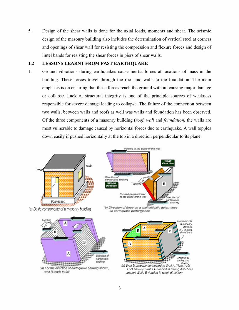
1. Ground vibrations during earthquakes cause inertia forces at locations of mass in the
building. These forces travel through the roof and walls to the foundation. The main
emphasis is on ensuring that these forces reach the ground without causing major damage
or collapse. Lack of structural integrity is one of the principle sources of weakness
responsible for severe damage leading to collapse. The failure of the connection between
two walls, between walls and roofs as well was walls and foundation has been observed.
Of the three components of a masonry building (roof, wall and foundation) the walls are
most vulnerable to damage caused by horizontal forces due to earthquake. A wall topples
down easily if pushed horizontally at the top in a direction perpendicular to its plane.
4
Damage in walls consisted of nearly vertical cracking of overhead of the openings,
diagonal tension, cracking of piers between adjacent openings, separation of orthogonal
walls, and partial out of plane collapse of second storey walls. Walls that are inadequately
anchored to the floor diaphragm can exhibit large diagonal cracks in the piers due to in
plane loads. If the mortar joints are weak, as in lime mortar, the cracks follow the joint.
2. The highest rate of damage in the buildings has been firstly, due to the failure of first and
second floor projections, secondly, due to the failure of ornamental balconies and parapet
walls, thirdly, due to the failure of arches over opening, and lastly, due to the collapse of
improperly tied gable ends.
3. The potential out-of-plane failure of non-structural elements (parapet, veneers, gables,
and unanchored walls) during earthquake constitutes the most serious life safety hazard
for this type of construction. They must be given proper design consideration for lateral
forces and should be braced or restrained.
4. In general, buildings with irregular plans experience more damage than rectangular
buildings. The damage is often concentrated at corners due to lack of a detailed analysis
that included the effects of odd shaped plans.
1.3 FAILURES MODES OF MASONRY Vibrations caused by earthquakes generate additional loading. Shear stresses develop
which cause damage to structural elements. Since masonry, which can be stressed
relatively high in compression, is weak in resisting bending and shear, collapse is often
the result. The different failures modes of masonry are:
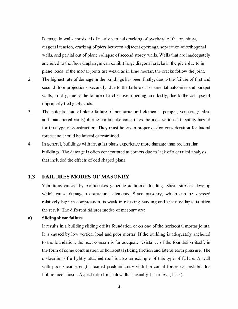
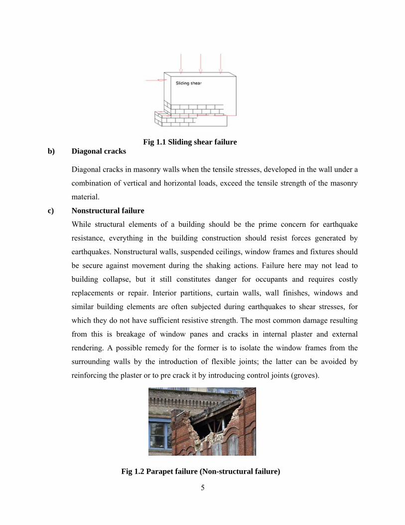
a) Sliding shear failure
It results in a building sliding off its foundation or on one of the horizontal mortar joints.
It is caused by low vertical load and poor mortar. If the building is adequately anchored
to the foundation, the next concern is for adequate resistance of the foundation itself, in
the form of some combination of horizontal sliding friction and lateral earth pressure. The
dislocation of a lightly attached roof is also an example of this type of failure. A wall
with poor shear strength, loaded predominantly with horizontal forces can exhibit this
failure mechanism. Aspect ratio for such walls is usually 1:1 or less (1:1.5) .
5
Fig 1.1 Sliding shear failure
b) Diagonal cracks
Diagonal cracks in masonry walls when the tensile stresses, developed in the wall under a
combination of vertical and horizontal loads, exceed the tensile strength of the masonry
material.
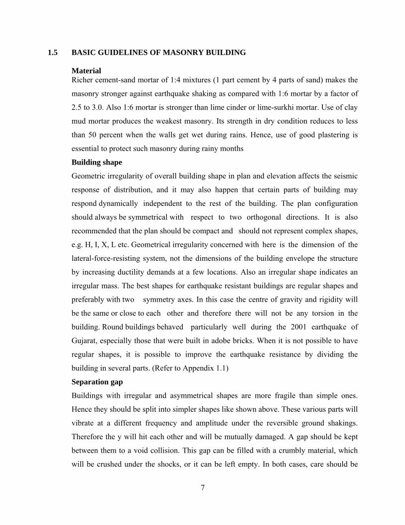
c) Nonstructural failure
While structural elements of a building should be the prime concern for earthquake
resistance, everything in the building construction should resist forces generated by
earthquakes. Nonstructural walls, suspended ceilings, window frames and fixtures should
be secure against movement during the shaking actions. Failure here may not lead to
building collapse, but it still constitutes danger for occupants and requires costly
replacements or repair. Interior partitions, curtain walls, wall finishes, windows and
similar building elements are often subjected during earthquakes to shear stresses, for
which they do not have sufficient resistive strength. The most common damage resulting
from this is breakage of window panes and cracks in internal plaster and external
rendering. A possible remedy for the former is to isolate the window frames from the
surrounding walls by the introduction of flexible joints; the latter can be avoided by
reinforcing the plaster or to pre crack it by introducing control joints (groves).
Fig 1.2 Parapet failure (Non-structural failure)

6
d) Failure due to overturning
The critical nature of the overturning effect has much to do with the form of the
building’s vertical profile. A wall that is too tall or too long in comparison to its thickness
is particularly vulnerable to shaking in its weak direction. Thus the tendency of a wall to
topple when pushed in the weak direction can be reduced by limiting its length-to-
thickness and height to- thickness ratios.
Fig 1.3 Failure due to overturning
Fig 1.4 Slender walls are vulnerable – height and length to be kept within limits.
7
1.5 BASIC GUIDELINES OF MASONRY BUILDING Material Richer cement-sand mortar of 1:4 mixtures (1 part cement by 4 parts of sand) makes the
masonry stronger against earthquake shaking as compared with 1:6 mortar by a factor of
2.5 to 3.0. Also 1:6 mortar is stronger than lime cinder or lime-surkhi mortar. Use of clay
mud mortar produces the weakest masonry. Its strength in dry condition reduces to less
than 50 percent when the walls get wet during rains. Hence, use of good plastering is
essential to protect such masonry during rainy months
Building shape
Geometric irregularity of overall building shape in plan and elevation affects the seismic
response of distribution, and it may also happen that certain parts of building may
respond dynamically independent to the rest of the building. The plan configuration
should always be symmetrical with respect to two orthogonal directions. It is also
recommended that the plan should be compact and should not represent complex shapes,
e.g. H, I, X, L etc. Geometrical irregularity concerned with here is the dimension of the
lateral-force-resisting system, not the dimensions of the building envelope the structure
by increasing ductility demands at a few locations. Also an irregular shape indicates an
irregular mass. The best shapes for earthquake resistant buildings are regular shapes and
preferably with two symmetry axes. In this case the centre of gravity and rigidity will
be the same or close to each other and therefore there will not be any torsion in the
building. Round buildings behaved particularly well during the 2001 earthquake of
Gujarat, especially those that were built in adobe bricks. When it is not possible to have
regular shapes, it is possible to improve the earthquake resistance by dividing the
building in several parts. (Refer to Appendix 1.1)
Separation gap
Buildings with irregular and asymmetrical shapes are more fragile than simple ones.
Hence they should be split into simpler shapes like shown above. These various parts will
vibrate at a different frequency and amplitude under the reversible ground shakings.
Therefore the y will hit each other and will be mutually damaged. A gap should be kept
between them to a void collision. This gap can be filled with a crumbly material, which
will be crushed under the shocks, or it can be left empty. In both cases, care should be
8
taken for the waterproofing of the joint with a system that does not link again both parts.
The separation gap must be minimum 25 mm for ground floor buildings and for higher
ones the gap should be increased by 10 mm per storey more. (Refer to Appendix 1.3)
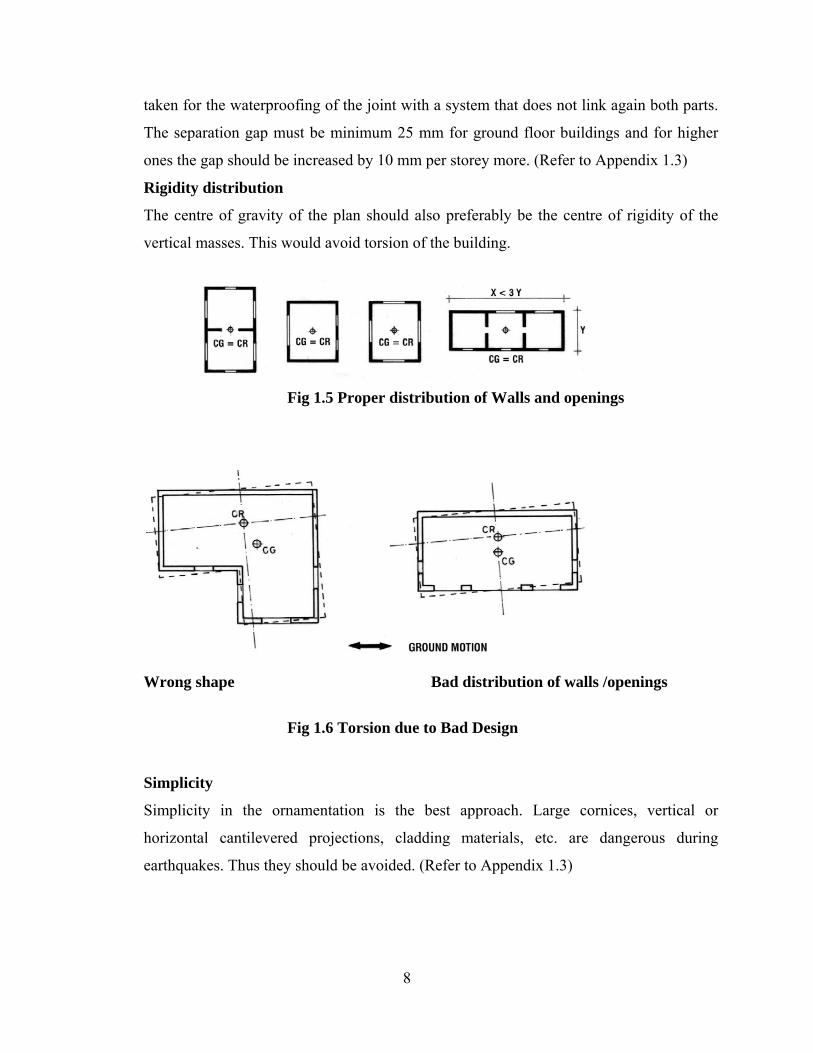
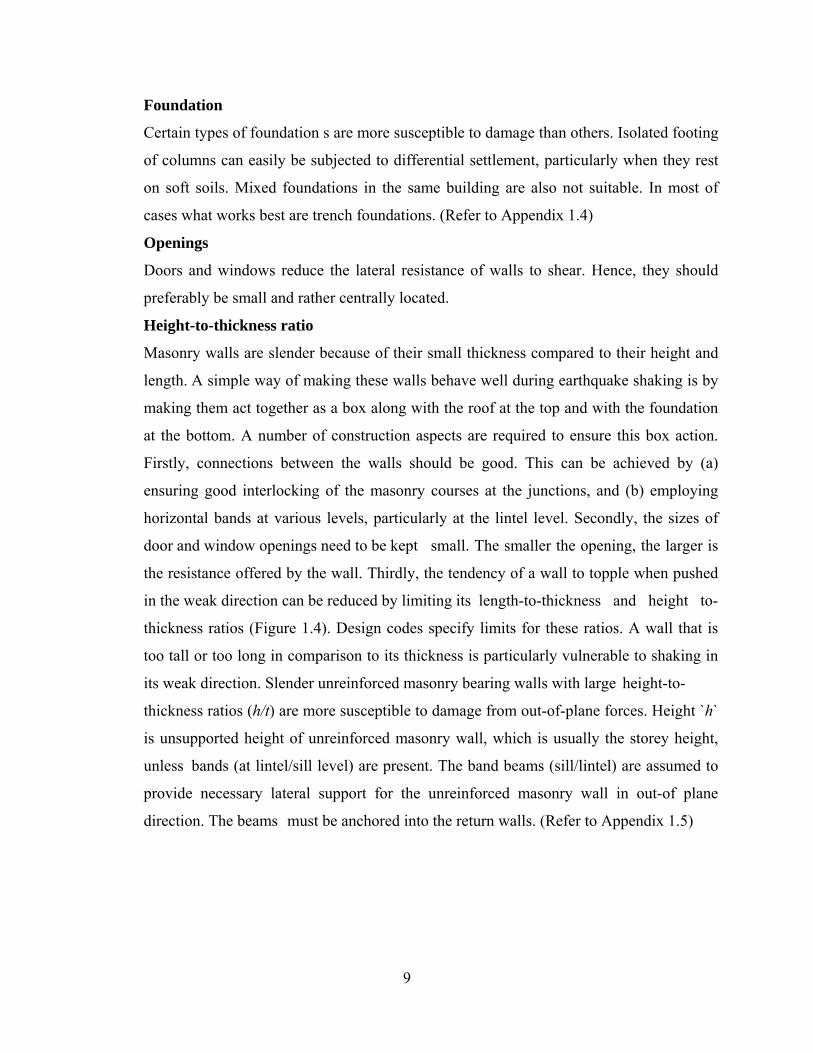
Rigidity distribution
The centre of gravity of the plan should also preferably be the centre of rigidity of the
vertical masses. This would avoid torsion of the building.
Fig 1.5 Proper distribution of Walls and openings
Wrong shape Bad distribution of walls /openings
Fig 1.6 Torsion due to Bad Design
Simplicity
Simplicity in the ornamentation is the best approach. Large cornices, vertical or
horizontal cantilevered projections, cladding materials, etc. are dangerous during
earthquakes. Thus they should be avoided. (Refer to Appendix 1.3)
9
Foundation
Certain types of foundation s are more susceptible to damage than others. Isolated footing
of columns can easily be subjected to differential settlement, particularly when they rest
on soft soils. Mixed foundations in the same building are also not suitable. In most of
cases what works best are trench foundations. (Refer to Appendix 1.4)
Openings
Doors and windows reduce the lateral resistance of walls to shear. Hence, they should
preferably be small and rather centrally located.
Height-to-thickness ratio
Masonry walls are slender because of their small thickness compared to their height and
length. A simple way of making these walls behave well during earthquake shaking is by
making them act together as a box along with the roof at the top and with the foundation
at the bottom. A number of construction aspects are required to ensure this box action.
Firstly, connections between the walls should be good. This can be achieved by (a)
ensuring good interlocking of the masonry courses at the junctions, and (b) employing
horizontal bands at various levels, particularly at the lintel level. Secondly, the sizes of
door and window openings need to be kept small. The smaller the opening, the larger is
the resistance offered by the wall. Thirdly, the tendency of a wall to topple when pushed
in the weak direction can be reduced by limiting its length-to-thickness and height to-
thickness ratios (Figure 1.4). Design codes specify limits for these ratios. A wall that is
too tall or too long in comparison to its thickness is particularly vulnerable to shaking in
its weak direction. Slender unreinforced masonry bearing walls with large height-to-
thickness ratios (h/t) are more susceptible to damage from out-of-plane forces. Height `h`
is unsupported height of unreinforced masonry wall, which is usually the storey height,
unless bands (at lintel/sill level) are present. The band beams (sill/lintel) are assumed to
provide necessary lateral support for the unreinforced masonry wall in out-of plane
direction. The beams must be anchored into the return walls. (Refer to Appendix 1.5)
10
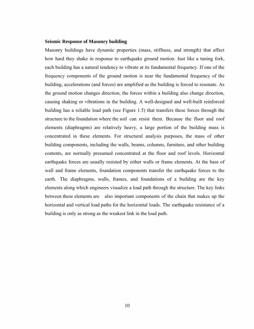
Seismic Response of Masonry building
Masonry buildings have dynamic properties (mass, stiffness, and strength) that affect
how hard they shake in response to earthquake ground motion. Just like a tuning fork,
each building has a natural tendency to vibrate at its fundamental frequency. If one of the
frequency components of the ground motion is near the fundamental frequency of the
building, accelerations (and forces) are amplified as the building is forced to resonate. As
the ground motion changes direction, the forces within a building also change direction,
causing shaking or vibrations in the building. A well-designed and well-built reinforced
building has a reliable load path (see Figure 1.5) that transfers these forces through the
structure to the foundation where the soil can resist them. Because the floor and roof
elements (diaphragms) are relatively heavy, a large portion of the building mass is
concentrated in these elements. For structural analysis purposes, the mass of other
building components, including the walls, beams, columns, furniture, and other building
contents, are normally presumed concentrated at the floor and roof levels. Horizontal
earthquake forces are usually resisted by either walls or frame elements. At the base of
wall and frame elements, foundation components transfer the earthquake forces to the
earth. The diaphragms, walls, frames, and foundations of a building are the key
elements along which engineers visualize a load path through the structure. The key links
between these elements are also important components of the chain that makes up the
horizontal and vertical load paths for the horizontal loads. The earthquake resistance of a
building is only as strong as the weakest link in the load path.

11
Fig 1.7 The load path for seismic forces in masonry buildings
Shear Wall Seismic Behaviour
Reinforced concrete and masonry shear walls are vertical seismic elements that resist
lateral loads in their plane. They are like vertical diving boards extending upward from
the foundation .The earthquake forces act horizontally in the plane of this vertical
cantilever. After the diaphragm shear force has been transmitted into the shear wall, the
shear wall behaves like an almost rigid diaphragm to resist these forces. In reinforced
walls, the reinforcing bars (rebar) are usually laid out in a regular rectangular pattern,
with bars running in both horizontal and vertical directions at uniform spacing. Shear
walls develop bending forces as well as shears, and all forces are transmitted to the
foundation elements, which resist the tendency of the seismic forces to push the wall over
in its own plane (Figure 1.7). This moment, which wants to rotate the shear wall, is called
an overturning moment. It increases from the top to the bottom of the building. This is
12
why reinforced shear walls have extra vertical bars placed at the ends. This boundary
reinforcing resists the bending forces, alternating vertical tension and compression, in the
wall. Bending forces can also develop around large openings in walls. This is why
additional trim bars are added at the edges of wall openings. Horizontal construction
joints in walls rely on shear transfer mechanisms such as built-in bumps or blocks, like
the vertical joints in rigid floor diaphragms. Seismic forces tend to push the shear wall
over causing an overturning moment .The overturning moment causes tension and
compression boundary forces in the shear wall. Sometimes walls in the same plane are
connected together with horizontal beams, called spandrels or coupling beams, at floor
and roof levels. During earthquakes, these components can also sustain damage similar to
that observed in walls. New construction standards require reinforcing patterns that favor
the more desirable, ductile behavior. In new construction, all shear walls are required by
code to be reinforced.
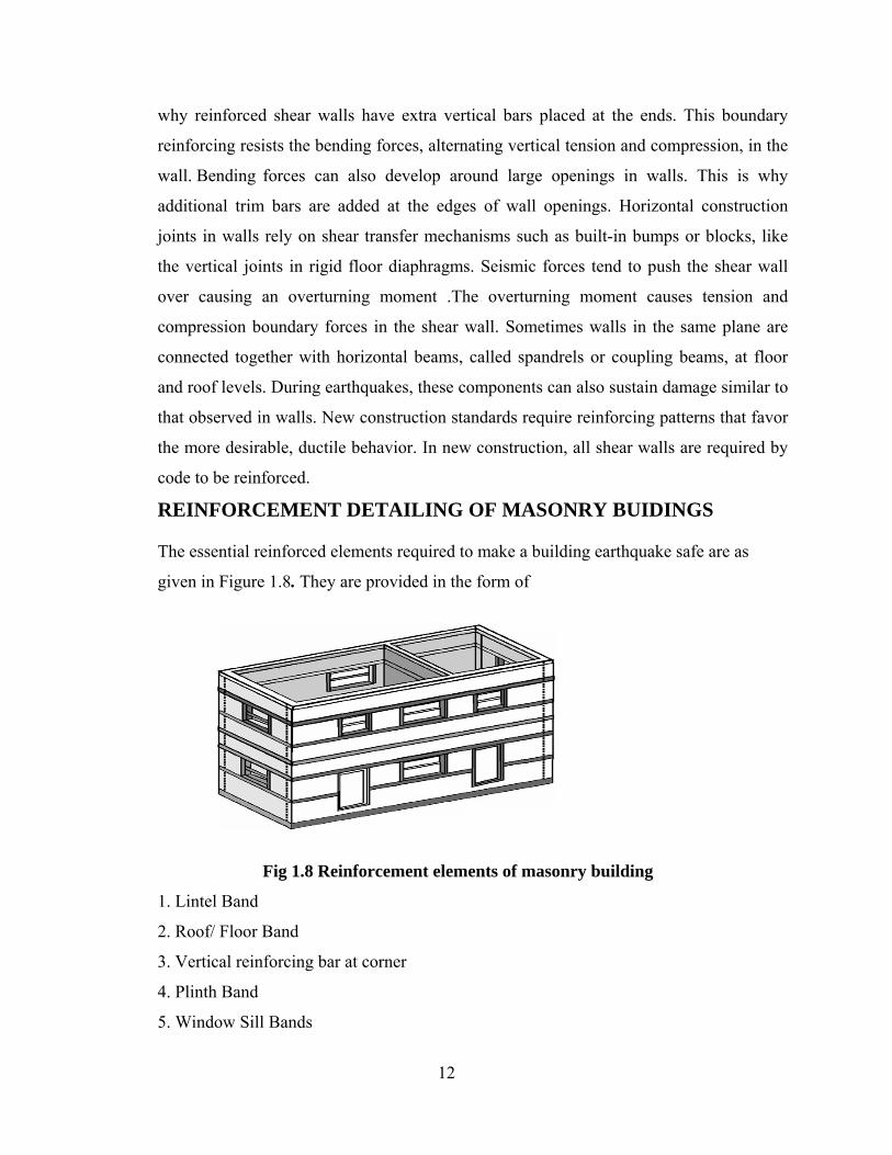
REINFORCEMENT DETAILING OF MASONRY BUIDINGS The essential reinforced elements required to make a building earthquake safe are as
given in Figure 1.8. They are provided in the form of
Fig 1.8 Reinforcement elements of masonry building
1. Lintel Band
2. Roof/ Floor Band
3. Vertical reinforcing bar at corner
4. Plinth Band
5. Window Sill Bands
13
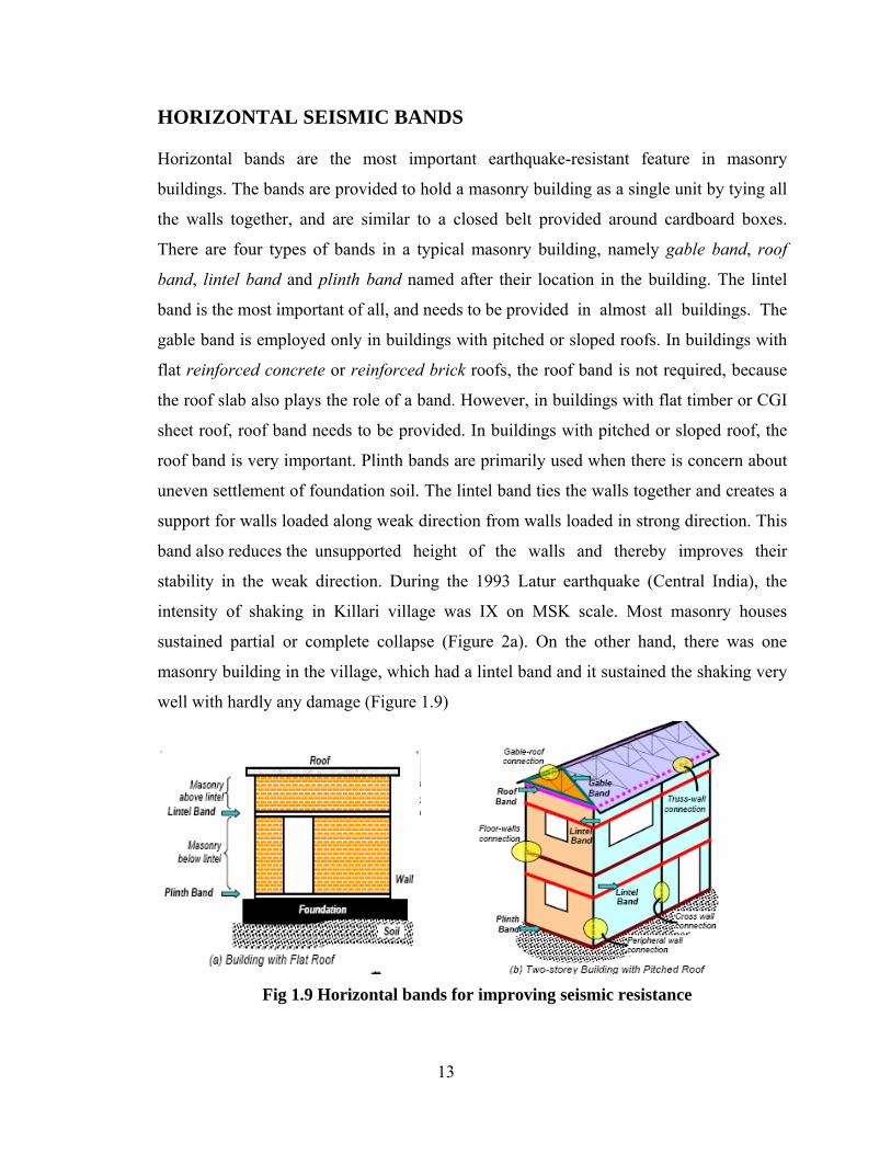
HORIZONTAL SEISMIC BANDS
Horizontal bands are the most important earthquake-resistant feature in masonry
buildings. The bands are provided to hold a masonry building as a single unit by tying all
the walls together, and are similar to a closed belt provided around cardboard boxes.
There are four types of bands in a typical masonry building, namely gable band, roof
band, lintel band and plinth band named after their location in the building. The lintel
band is the most important of all, and needs to be provided in almost all buildings. The
gable band is employed only in buildings with pitched or sloped roofs. In buildings with
flat reinforced concrete or reinforced brick roofs, the roof band is not required, because
the roof slab also plays the role of a band. However, in buildings with flat timber or CGI
sheet roof, roof band needs to be provided. In buildings with pitched or sloped roof, the
roof band is very important. Plinth bands are primarily used when there is concern about
uneven settlement of foundation soil. The lintel band ties the walls together and creates a
support for walls loaded along weak direction from walls loaded in strong direction. This
band also reduces the unsupported height of the walls and thereby improves their
stability in the weak direction. During the 1993 Latur earthquake (Central India), the
intensity of shaking in Killari village was IX on MSK scale. Most masonry houses
sustained partial or complete collapse (Figure 2a). On the other hand, there was one
masonry building in the village, which had a lintel band and it sustained the shaking very
well with hardly any damage (Figure 1.9)
Fig 1.9 Horizontal bands for improving seismic resistance
14
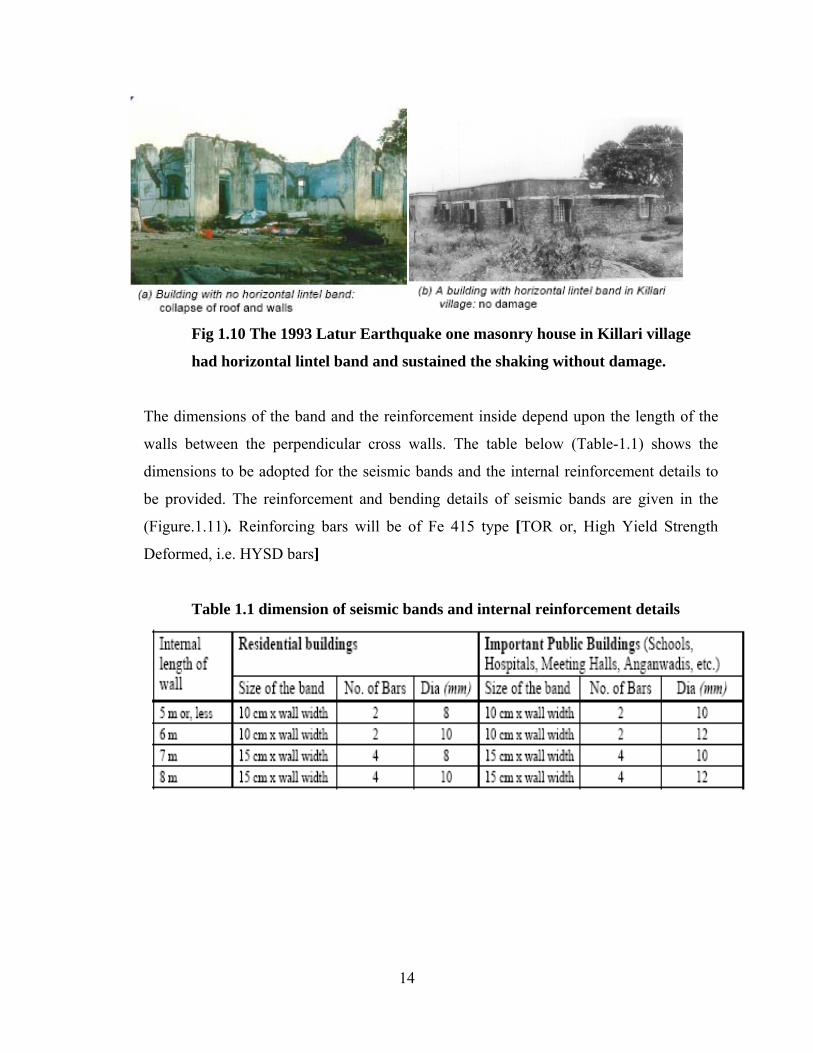
Fig 1.10 The 1993 Latur Earthquake one masonry house in Killari village
had horizontal lintel band and sustained the shaking without damage.
The dimensions of the band and the reinforcement inside depend upon the length of the
walls between the perpendicular cross walls. The table below (Table-1.1) shows the
dimensions to be adopted for the seismic bands and the internal reinforcement details to
be provided. The reinforcement and bending details of seismic bands are given in the
(Figure.1.11). Reinforcing bars will be of Fe 415 type [TOR or, High Yield Strength
Deformed, i.e. HYSD bars]
Table 1.1 dimension of seismic bands and internal reinforcement details

15
Fig 1.11 Reinforcement and bending details of seismic bands
Why are horizontal bands necessary in masonry buildings? DESIGN OF LINTEL BANDS
During earthquake shaking, the lintel band undergoes bending and pulling actions
(Figure1.12). To resist these actions, the construction of lintel band requires special
attention. Bands can be made of wood (including bamboo splits) or of reinforced concrete
(RC) (Figure 1.13); the RC bands are the best. The straight lengths of the band must be

16
properly connected at the wall corners. This will allow the band to support walls loaded
in their weak direction by walls loaded in their strong direction. Small lengths of wood
spacers (in wooden bands) or steel links (in RC bands) are used to make the straight
lengths of wood runners or steel bars act together. In wooden bands, proper nailing of
straight lengths with spacers is important. Likewise, in RC bands, adequate anchoring of
steel links with steel bars is necessary.
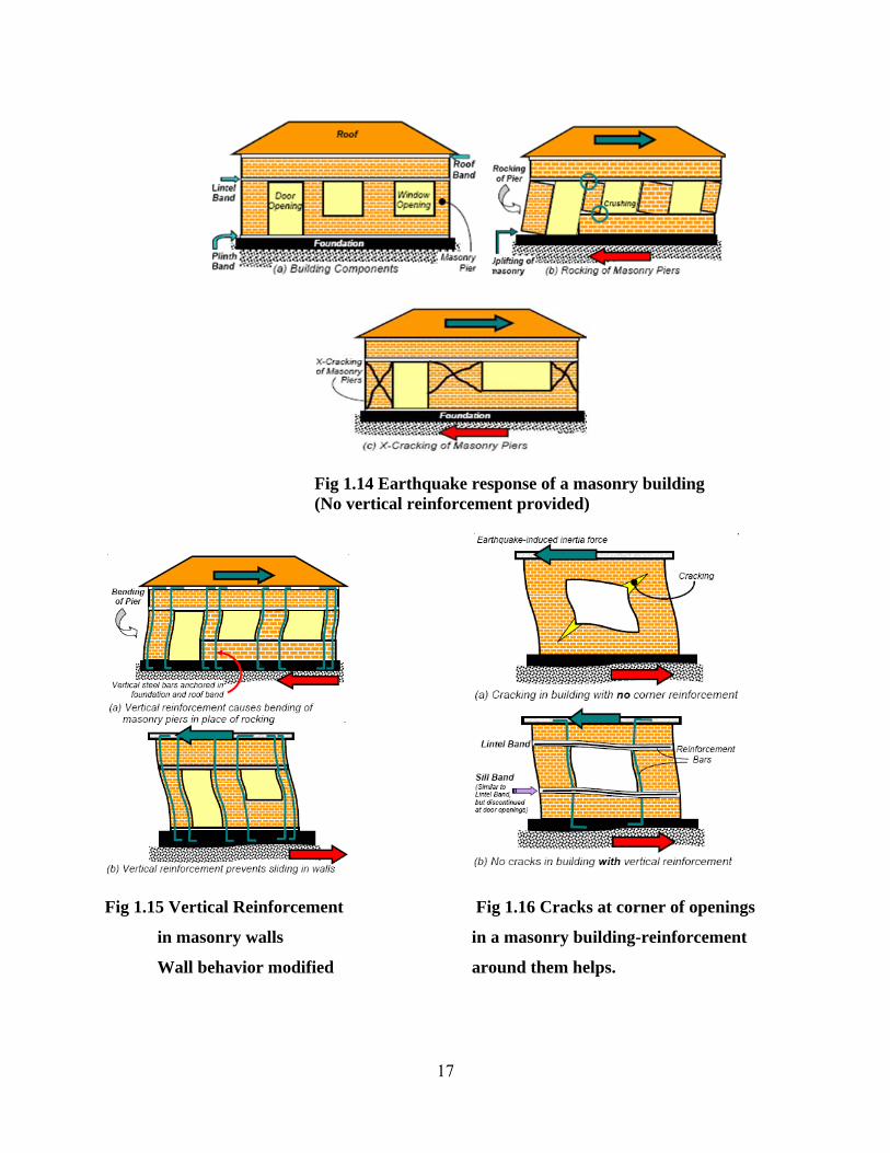
Fig 1.12 Cross-section of lintel bands Fig 1.13 Horizontal bands Why is vertical Reinforcement required in masonry Buildings?
Embedding vertical reinforcement bars in the edges of the wall piers and anchoring them
in the foundation at the bottom and in the roof band at the top (Figure 1.12), forces the
slender masonry piers to undergo bending instead of rocking. In wider wall piers, the
vertical bars enhance their capability to resist horizontal earthquake forces and delay the
X-cracking. Adequate cross-sectional area of these vertical bars prevents the bar from
yielding in tension. Further, the vertical bars also help protect the wall from sliding as
well as from collapsing in the weak direction.
17
Fig 1.14 Earthquake response of a masonry building (No vertical reinforcement provided)
Fig 1.15 Vertical Reinforcement Fig 1.16 Cracks at corner of openings
in masonry walls in a masonry building-reinforcement
Wall behavior modified around them helps.
18
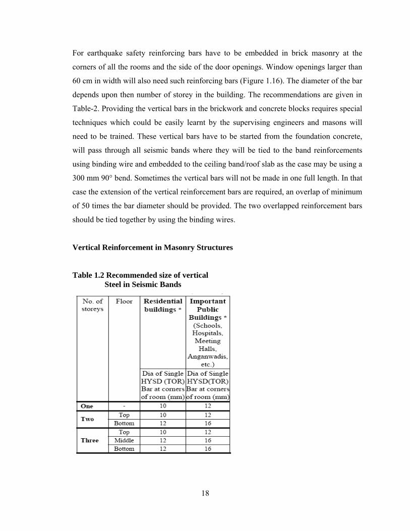
For earthquake safety reinforcing bars have to be embedded in brick masonry at the
corners of all the rooms and the side of the door openings. Window openings larger than
60 cm in width will also need such reinforcing bars (Figure 1.16). The diameter of the bar
depends upon then number of storey in the building. The recommendations are given in
Table-2. Providing the vertical bars in the brickwork and concrete blocks requires special
techniques which could be easily learnt by the supervising engineers and masons will
need to be trained. These vertical bars have to be started from the foundation concrete,
will pass through all seismic bands where they will be tied to the band reinforcements
using binding wire and embedded to the ceiling band/roof slab as the case may be using a
300 mm 90° bend. Sometimes the vertical bars will not be made in one full length. In that
case the extension of the vertical reinforcement bars are required, an overlap of minimum
of 50 times the bar diameter should be provided. The two overlapped reinforcement bars
should be tied together by using the binding wires.
Vertical Reinforcement in Masonry Structures
Table 1.2 Recommended size of vertical Steel in Seismic Bands

19
Fig 1.17 Typical Details of Providing Vertical
Steel Bars in Brick Masonry
Vertical Reinforcement at jambs at openings
Fig 1.18.Typical details for providing vertical steel bars at openings

20
Foundation
Certain types of foundation s are more susceptible to damage than others. Isolated footing
of columns can easily be subjected to differential settlement, particularly when they rest
on soft soils. Mixed foundations in the same building are also not suitable. In most of
cases what works best are trench foundations. Foundation width 'B' should be decided by
the load coming on the foundation and the bearing capacity. Masonry width may be
reduced by ½ times T in every step of 150 mm height.
Fig 1.19 Foundation Details

21
CHAPTER 2
BASIC STEPS OF ANALYSIS
AND
DESIGN OF MASONRY BUILDING

22
PROCEDURE FOR ANALYSIS OF THREE STOREYED MASONRY BUILDING
2.1 STEP 1: DETERMINATION OF DESIGN EARTHQUAKE FORCES
“Equivalent Static seismic forces Procedure “being the simplest method of analysis was
adopted to determine the seismic forces. Since the forces depend upon code based
fundamental period of structures with some empirical modifier it required less
computational effort.
a) The design base shear was computed as a whole, than distributed along the height of the
buildings based on simple formulas appropriate for buildings with regular distribution of
mass and stiffness.
b) The design Lateral force obtained at each floor level was distributed to individual Lateral
Load resisting elements depending upon floor diaphragm action.
c) In case of rigid diaphragm ( reinforced concrete monolithic slab beam floors or those
consisting of prefabricated/precast elements with topping reinforced screed was taken as
rigid diaphragm) action, the total shear in any horizontal plane was distributed to the
various elements of Lateral force resisting, system on the basis of relative rigidity.
Following are the major steps of Equivalent static Analysis:
2.1.1 SIESMIC WEIGHT CALCULATIONS:
The seismic weight of each floor was taken as its full Dead Load plus appropriate amount
of Imposed Load. While computing the seismic weight of each floor, the weight of
columns and walls in any storey was equally distributed to the floors above & below the
storey. The weight of Live Load for seismic calculation was taken as zero.
Dead Load and Live load at roof level
The Dead Load and the Live Load at roof level Wr consisted of the sum of (i) Weight
of roof, (ii) Weight of walls and (iii) Weight of live load (LL).

23
i) Weight of roof was calculated as the product of length, breadth and weight of the roof
slab.
ii) Weight of walls is calculated assuming half weight of walls at second storey is lumped at
roof.
iii) Weight of live load (LL) for seismic calculation is taken as zero
DD and LL Load at each storey floor level: The Dead Load and the Live Load at second storey roof level (Wfi) where i is the ith
storey consisted of the sum of (i) Weight of floor, (ii) Weight of walls and (iii) Weight of
Live Load (LL).
i) Weight of floor was calculated as the product of length, breadth and weight of the floor
slab.
ii) Weight of walls was calculated assuming half weight of walls at ith storey and half
weight of walls at previous storey above which is lumped at roof.
iii) Live load is taken according to [IS 875 Part I]1
DD and LL Load at first storey floor level:
The Dead Load and the Live Load at first storey roof level (Wf2) consisted of the sum of
(i) Weight of floor, (ii) Weight of walls and (iii) Weight of Live Load (LL).
i) Weight of floor was calculated as the product of length, breadth and weight of the floor
slab.
ii) Weight of walls was calculated assuming half weight of walls at each storey and half
weight of walls at previous storey is lumped at roof.
Total seismic weight of building = Wr + ∑Wfi + Wf2

24
2.1.2 TIME PERIOD CALCULATIONS
The approximate fundamental natural period of a masonry building can be calculated
from the clause 7.6.2 of [IS 1893(Part 1):2002]2 as,
Ta = 0.09 h/√d
Where,
h= height of building in m, {i.e, (first storey) + (second storey)+(third storey) }
d= base dimension of building at the plinth level, in m, along the considered direction of
lateral force (i.e, assuming earthquake in E-W direction)
Ah = (ZI Sa)/ (2Rg)
The total design lateral base shear (VB) along the direction of motion is given by
VB =AhW
WHERE DOES THE EARTHQUAKE FORCE ACT? Earthquakes force is an inertia force. It acts on each mass particle of the structure and
acts throughout the structure and is proportional to the mass and acceleration.
Again, in case of buildings, the floors are generally rigid in their plane and it can be
assumed that all the points on the floor of a symmetric building move together with same
displacement and acceleration. On the other hand, the acceleration increases along the
height of the building and different floors have different acceleration.
Therefore for the sake of convenience, we assumed
The mass is lumped in certain points. (At the centre of its floors).
i) The earthquake forces are acting at these masses.
ii) The mass of the half of the storey above and half of the storey below is lumped at floor
level.
iii) The force Qi acting at a floor level is proportional to the lumped mass and the
acceleration.
iv) The earthquake force is increasing along the height of the building, as the acceleration at
floor level is increasing.
25
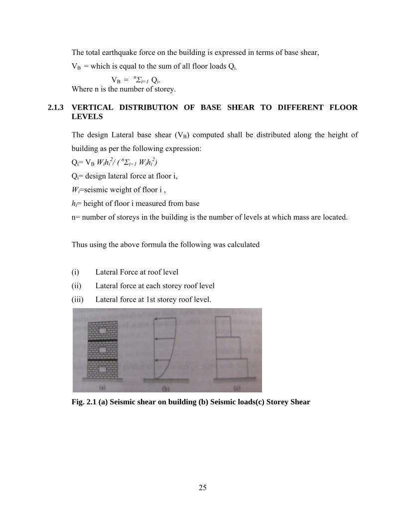
The total earthquake force on the building is expressed in terms of base shear,
VB = which is equal to the sum of all floor loads Qi. VB = nΣi=1 Qi. Where n is the number of storey. 2.1.3 VERTICAL DISTRIBUTION OF BASE SHEAR TO DIFFERENT FLOOR LEVELS The design Lateral base shear (VB) computed shall be distributed along the height of
building as per the following expression:
Qi= VB Wihi2/ ( nΣi=1 Wihi
2)
Qi= design lateral force at floor i,
Wi=seismic weight of floor i ,
hi= height of floor i measured from base
n= number of storeys in the building is the number of levels at which mass are located.
Thus using the above formula the following was calculated
(i) Lateral Force at roof level
(ii) Lateral force at each storey roof level
(iii) Lateral force at 1st storey roof level.
Fig. 2.1 (a) Seismic shear on building (b) Seismic loads(c) Storey Shear

26
Distribution of Lateral forces In order to transfer the seismic forces to the ground, there should be a continuous load
path in the building.
The general load path is as follows:
i) Earthquake forces, which originate in all the elements of the building, are delivered
through the transverse wall of the building and it is bent between the floors.
ii) The lateral loads are transmitted from these transverse walls to the side shear wall by
horizontal floor and roof diaphragms.
iii) The diaphragms distribute these forces to vertical resisting components if any which
transfer the forces into the foundation, the diaphragms must have adequate stiffness and
strength to transmit these forces.
iv) The distribution of lateral forces in the masonry buildings will depend upon the flexibility
of horizontal diaphragm.
Fig 2.2. Lateral force distribution in a box type building (a) Box type masonry building subjected to lateral load (b) Bend of first storey/second storey transverse walls (c) distribution of lateral forces in second storey (d) Distribution of lateral forces in first storey.
The rigidity of the diaphragms is classified into two groups on relative flexibility: Rigid and flexible diaphragm.
27
RIGID DIAPHRAGM i) A diaphragm may be considered rigid when its midpoint displacement under lateral load
is less than twice the average displacements at its ends.
ii) Rigid diaphragm distributes the horizontal forces to the vertical resisting elements in
direct proportion to the relative rigidities.
ii) It is based on the assumption that the diaphragm does not deform itself and will cause
each vertical element to deflect the same amount.
iv) Rigid diaphragms capable of transferring torsional and shear deflection forces are also
based on the assumption that the diaphragm and shear walls undergo rigid body rotation
and this produces additional shear forces in the shear wall.
v) Rigid diaphragms consist of reinforced concrete diaphragms, precast concrete
diaphragms and composite steel check.
FLEXIBLE DIAPHRAGM i) A Diaphragm is considered flexible, when the midpoint displacement, under lateral load,
exceeds twice the average displacements of the supports.
ii) It is assumed that the relative stiffness of these non-yielding end supports is very great
compared to that of the diaphragm.
iii) Diaphragms are often designed as simple beams between end supports and distribution of
the lateral forces to the vertical resisting elements on a tributary width, rather than
relative stiffness.
iv) Flexible diaphragm is not considered to be able capable of distributing torsional
rotational forces. Flexible diaphragms consist of diagonally sheathed wood diaphragms,
etc.

28
2.2 STEP 2: DETERMINATION OF WALL RIGIDITY
2.2.1 GENERAL GUIDELINES
i) The lateral load capacity of shear wall is mainly dependent on the in plane resistance
rather than out of plane stiffness.
ii) The distribution of Lateral Load to the shear walls is based on the relative wall rigidities
if a rigid diaphragm supports the walls and the segment of the wall deflects equally.
iii) The rigidity of shear wall is dependent on its dimensions, modulus of Elasticity (Em) ,
modulus of Rigidity ( Gm) and the support conditions.
iv) The relative rigidity of shear wall elements is inversely proportional to their deflections
when loaded with a unit horizontal force.
2.2.2 FACTORS AFFECTING RIGIDITY
1) Control joints are complete structural separations that break shear wall into elements like
lintel bend. The elements must be considered as isolated members during shear wall
rigidity analysis. The number and location of control joints within the total length of a
wall may significantly affect elements rigidities especially flexure deformation.
2) Openings for doors, windows etc reduce the rigidity of shear wall elements. If openings
are very small, their effect on the overall state of stress in a shear wall will become
minor. Large openings will have pronounced effect when the openings in a shear wall
become so large that the resulting wall approaches an assembly similar to a rigid frame or
a series of elements linked by connecting beams, the walls will be analyzed accordingly.
Pier Analysis
In masonry structures, it is generally assumed that in one and two storey buildings the
walls may be considered cantilevered and the segment of the walls between adjacent
openings are called piers and might be considered fixed at top and bottom, depending
upon the relative rigidness of the walls versus those of the floor diaphragms.
The main assumptions in the analysis are (Schneider and Dickey, 1994):
a) Rotational deformations of the portions above and below the openings are much smaller
than those of the piers between the openings and are neglected.

29
b) Points of contra flexure are assumed at the midpoints of the piers and shears are assumed
to be carried among the piers such that their top deflects by equal amount.
c) Lateral forces will be transformed to the various parallel resisting elements in direct
proportion to their stiffness.
i) Stiffness refers to the lateral force magnitude required to produce a unit deflection
ii) Relative, rather than absolute stiffness can be computed since each wall is only being
compared to the combined stiffness of the entire wall system.
Cantilever pier or wall
If the pier or wall is fixed only at the bottom and top is free to translate and rotate, it is
considered a cantilevered wall.
When a force (P) is applied at the top of a pier , it will produce a deflection, , ∆c that is
the sum of the deflections due to bending moment (∆’m ) Plus that due to the shear (∆v )
Fig2.3 Cantilever Pier or wall behavior to deflection
∆c = ∆m +∆v
∆m = deflection due to flexural bending
∆v = Deflection due to shear
P = lateral force on pier
h = height of pier
A = cross-section of pier
Em = modulus of elasticity in compression

30
∆c =P/ Emt [4(h/d)3+3(h/d)
Rigidity of cantilever Pier Rc = 1/ ∆c = Emt/[(4(h/d)3+3(h/d)]
Fixed Pier or Wall
Fixed pier or wall fixed at top and bottom, the deflection from a force, P
∆f = ∆m +∆v
=Ph3/12EmI + 1.2 Ph/AGm
∆f =P/ Emt [(h/d)3+3(h/d)]
Rigidity of fixed pier
Rf=1/ ∆f =Emt/ [(h/d)3+3(h/d)]
i. Very squat shear wall (h/d<0.25), rigidities based on shear deformation are reasonably
accurate
ii. For deformation height of shear wall (0.25<h/d<4.0), including both the components of
deflection
iii. For high h/d ratio, the effect of shear deformation is very small and rigidity based on
flexural stiffness is reasonably accurate ( Drydale, Hamid and Baker, 1994 ).
Horizontal and Vertical Combinations
If the shear wall segments are combined horizontally, the combined rigidity
R = Rc1+ Rc2 + Rc3, if the segments are combines vertically 1/Rc1 + 1/Rc2 + 1/Rc3
Fig 2.4 a) Horizontal combination and b) Vertical combination of Rigidity

31
Method for calculating the rigidity of the wall with opening
The following steps are required for calculating the rigidity of wall with opening.
• Assume full wall as solid calculate the deflection of the solid wall as a cantilever, ∆solid(c)
• Take a StripA of height equal to the height of largest opening. Calculate deflection of
this strip. (∆strip of highest opening(c) .
• Divide the wall in StripA into No. of segments .Assuming each solid strip as solid
calculate the deflections of all the piers (∆piers(f) )
• Calculate total defection of the wall with opening
(∆total)= ∆solid(c)- ∆strip+ ∆piers(f)
The reciprocal of this value becomes relative rigidity of the wall. [R = 1/(∆total)]
3) A shear wall element which is structurally internal at its end with a shear wall that is
normal to the element forming an ‘L’ or ‘T’ in plane shape is called a corner element.
The rigidity of a corner element is greater than that of a straight element. The amount of
increase in rigidity is taken into account empirically when rigidity analysis is done.

32
2.2.3 PROCEDURE FOLLOWED IN RIGIDITY CALCULATION
a) The rigidity of the piers and solid wall are calculated by taking solid wall as cantilever
pier, the piers and strip of wall are assumed as fixed pier.
Rigidity of cantilever pier RC = Et / [4(h/d)3+3(h/d)]
Rigidity of cantilever pier Rf = Et / [(h/d)3+3(h/d)]
b) They are then combined according to their horizontal and vertical position.
Total Rigidity of the wall is calculated as
∆wall = ∆solidwall - ∆strip)+ ∆piers combined
c) The north wall and south wall rigidity are calculated and then the relative
stiffness of each wall is calculated. North shear wall =Rwall(north) / (Rwall(north) +Rwall(south))
South shear wall = Rwall(south) / (Rwall(north) +Rwall(south)
Fig.2.5 Building position and seismic force direction
33
2.3 STEP 3: DETERMINATION OF TORSIONAL FORCES To calculate the shear forces due to torsion, first the location of the centre of mass and the
centre of rigidity was calculated.
2.3.1 LOCATION OF THE CENTRE OF MASS
i) First the respective weights (W) of walls (N-wall, S-wall, E-wall and W-wall) and Roof
Slab were found out in KN.
ii) The X-coordinate and Y-coordinates (in m) were found out.
Then for each item (Roof Slab, N-Wall, S-wall, E-wall, and W-wall) the statical moments
about a point (WX and WY in KN-m) were calculated using the respective weights of
walls as forces in the moment summation.
iii) The cumulative of ΣW, ΣWX and ΣWY were found out.
The centre of Mass (XCM and YCM ) were found out using the formulae
XCM = ΣWX/ ΣW
YCM = ΣWY/ ΣW
Because of symmetrical layout of the building, the centre of mass occurs near the centre
of building.
2.3.2 LOCATION OF THE CENTRE OF RIGIDITY
i) First the relative stiffness (Rx and Ry ) of the walls (N-wall, S-wall, E-wall and W-wall)
were found out.
ii) The X-coordinate and Y-coordinates (in m) were found out.
iii) Then for each item (N-Wall, S-wall, E-wall, and W-wall) the statical moments about a
point (YRx and XRy) were calculated using the relative stiffness of the walls as forces in
the moment summation. . The stiffness of the slab was not considered in the
determination of centre of rigidity.
iv) The cumulative of ΣRx, ΣRy , Σ X Ry and Σ YRx were found out.
The centre of Rigidity (XCR and YCR ) were found out using the formulae
XCR = Σ XRy / Σ Ry
YCR =Σ YRx / Σ Rx
Torsional Eccentricity
Torsional Eccentricity in y- direction:
Eccentricity between centre of mass and centre of rigidity
34
ey = YCM - YCR
Adding minimum 5% accidental eccentricity
=(0.05×Y)
Total eccentricity = ey +(0.05×Y)
Torsional eccentricity in x- direction
Eccentricity between centre of mass and centre of rigidity
ex= XCM - XCR
Adding minimum 5% accidental eccentricity
(0.05×X)
Total eccentricity = ex +(0.05×X)
2.3.3 TORSIONAL MOMENT
The torsional moment due to E-W seismic force rotate the building in y direction.
Hence MTX= Vx Cy
Similarly if considered seismic force in N-S direction
MTy= Vy Cx
Vy = Vx because Sa/g is constant value of 2.5 for Time period 0.11≤T≤.55
2.3.4 DISTRIBUTION OF FORCES IN NORTH AND SOUTH SHEAR WALLS STEPS TO BE FOLLOWED i) Since we are considering the seismic force only in E- W direction, the walls in N-S
direction will resist the forces and the walls in E-W direction were ignored.
ii) Computation of Relative Stiffness (Rx ),
iii) Calculation of distance of considered wall from centre of rigidity (dy =2Y- ey ) in m, Rx
dy and Rx dy2 for both N-wall and S-wall.
iv) Negative torsional shear was neglected.
v) Calculation of distribution of direct shear (KN)
Direct shear force from North-wall = Vx RN
Direct shear force from South-wall =VxRS
35
Calculation of Torsional shear force (KN)
Torsional force in North-wall = (ΣRx dy )/ (ΣRx dy2) × (Vx ey)
Torsional force in South-wall = (ΣRx dy )/ (ΣRx dy2) × (Vx ey)
2.3.5 DISTRIBUTION OF FORCES IN EAST AND WEST SHEAR WALLS
STEPS TO BE FOLLOWED
i) Computation of Relative Stiffness (Ry ),
ii) Calculation of distance of considered wall from centre of rigidity (dx =2X- ex ) in m, Ry
dx and Ry dx2 for both E-wall and W-wall.
iii) Calculation of distribution of direct shear force (KN)
Direct shear force from East-wall =VyRE
Direct shear force from West-wall = Vy RW
Calculation of Torsional shear force:
Torsional force in East-wall = (ΣRy dx )/ (ΣRy dx2) × (Vy ex)
Torsional force in West-wall = (ΣRy dx )/ (ΣRy dx2) × (Vy ex)
2.3.6 DISTRIBUTION OF THE TOTAL SHEAR TO INDIVIDUAL PIERS WITHIN THE WALL The shear carried by the North and South shear walls is now distributed to individual
piers on the basis of their respective stiffness. Shear in pier group is further subdivided in
vertical piers 1, 2, 3 on proportion to their stiffness.
36
2.4 STEP 4: DETERMINATION INCREASE IN AXIAL LOAD DUE TO
OVERTURNING
In shear wall analysis the principal forces are
i) In plane shear (direct + torsional)
ii) In plane moment (in plane shear × ½ height of pier )
iii) Dead & Live Load carried by the pier.
iv) Lateral forces from Wind or Earthquakes which create severe overturning moments on
buildings. If the overturning moment is great enough it may overcome the dead weight of
the structure & may cause tension at the end of the piers of shear walls. It may also
induce high compression forces in the pier of walls that may increase the axial load in
addition to the dead load and live load.
The increase in axial load in piers due to overturning moments was evaluated as below:
Overturning moment at ith floor level
(Movt )2 = Vr ( hi+hi+1) + Vi+1 hi
(where’ i’ is the floor level and Vi is the seismic force at ith floor level
Total overturning moment on pier in the first storey Movt
=(Movt)2+(total V) × ( distance to the second floor level from critical level of the pier in
the ith storey
Let at the sill height of the pier = hir
Thus the axial load on a pier due to overturning change to Povt is
Povt = (Movt ) (liAi)/In
li = Distance from the centre of gravity of net wall section in the ith storey to the
centroid of the pier
= nΣi=1 (liAi)/ ΣAi
Ai= cross-sectional area of pier in question
In= Moment of Inertia of net wall section in first storey
= nΣi=1 liAi2
Movt =Total shear (Vx) × (vertical distance between second floor to critical plane of
weakness, assuming at the level of sill) + (Applied overturning Moment at second floor
level)

37
It is assumed that the stiffness of second storey walls is the same as first storey, the total
direct shear in E-W direction of seismic load i.e, in X direction is divided in North and
South shear wall is proportional to their stiffness
Direct shear in North Wall (VNX )
Direct shear in South Wall (VSX )
Distribution of Lateral force along the height of North and South wall is
2.4.1 DISTRIBUTION OF LATERAL FORCES
Lateral force at a height hi= VNX × Wihi2/ ( nΣi=1 Wihi
2)
Using the above formula the following were calculated for both North and South shear
wall
(i)Lateral force at each storey roof level
Movt
= Vr (hi +hi+1) + Vi+1hi + (total V) × (distance of ith floor level from critical level of
the pier in the (i-1) storey)
Increase in axial Load due to overturning moment
Povt = Movt LiAi /In
Where IiAi = centroid of net section of wall.
In = Moment of inertia of net section of wall.
2.4.2 CALCULATION OF CENTROID OF NET SECTION OF WALL
Distance from left edge to centroid of net section of wall
= Σ AiI / ΣI
2.4.3 CALCULATION OF MOMENT OF INERTIA OF NET SECTION OF WALL
In= I + Aili2
Where I= td3/12 (in m4 )
2.4.4 INCREASE IN AXIAL LOAD IN PIERS OF NORTH WALL
Increase in axial Load due to overturning moment
= Povt = Movt LiAi /In
Where liAi = centroid of net section of wall
In = Moment of inertia of net section of wall

38
2.4.5 CALCULATION OF CENTROID AND MOMENT OF INTERTIA OF NET
SECTION OF WALL
Centroid
Centroid of each pier is calculated and then for the net section of the wall
Distance from left edge to centroid = Σ Ail / Σl
Where l= distance from lift edge of wall to centroid of pier and Ai = Area
Moment of Inertia
Moment of inertia of each pier is calculated and then for the net section of the wall by
formula below.
Where In= I + Aili2
I= td3/12
I is the moment of inertia of each pier, where d is the width and t is the thickness of the
pier
2.4.6 INCREASE IN AXIAL LOAD IN INDIVIDUAL PIERS OF SOUTH SHEAR
WALL
Overturning moment in wall Movt
= Total shear at third floor X critical height (hcr) + Movt(2)
Increase in axial Load due to overturning moment
= Povt = Movt LiAi /In
Where liAi = centroid of net section of wall
In = Moment of inertia of net section of wall

39
2.5 STEP 5: DETERMINATION OF PIER LOADS, MOMENTS AND SHEAR
2.5.1 PROCEDURE
i) Dead load intensity is calculated for each wall (North and south wall) per metre length of
wall
Dead load intensity= weight of first storey from IInd floor to sill level+ weight of each
storey+ weight of floor at each storey level (assuming North and South wall will take
equal amount of load+ weight of roof)
ii) Live load intensity is also calculated as [weight of floor at each storey level (assuming
north and south wall will take equal amount of load+ live load of roof]
iii) Pd= Effective Loading Width of Pier × Dead Load Intensity in KN/m
PL= Effective Loading Width of Pier × live Load Intensity in KN/m
Effective Loading width of pier = Width of pier + ½ of each adjacent opening of pier
iv) Shear VE is calculated from the distribution of total shear to individual piers
v) Moment = VE × h/2 where h is the height of pier

40
2.6 STEP 6: DESIGN OF SHEAR WALLS FOR AXIAL LOAD AND
MOMENTS i) Moment (M) calculated in step 5 is taken into calculation.
ii) Effective depth of pier is calculated taking some cover deffective=dtotal-cover
iii) Area of jamb steel which are to provided at the pier boundary is calculated as follows
As=M/(ƒs×0.9× deffective)
ƒs=0..55 Fe=0.55 ×415=230 N/mm2
iv) For the calculated area of jamb steel the no.of steel bars are assumed and arrangement is
done according to IS 4326:1993
v) Adequacy of individual piers under compression and moment is checked by interaction
formula. (ƒa/Fa) + (ƒb/Fb) ≤1.33
Where ƒa= Ptotal (Pd+ PL+ Povt) / (width of pier (d) ×t)
ƒb= M/(td2/6)
Fa= Permissible compressive stress=2.5 N/mm2
Fb=Permissible bending stress=2.5+0.25×2.5=3.125(as per IS :1905)

41
2.7 STEP 7: DESIGN OF SHEAR WALL FOR SHEAR In load bearing masonry buildings, the walls, which carry gravity loads also acts as shear
walls to resist lateral load. The structural walls parallel to lateral load and subjected to in-
plane (shear) forces and bending are called shear walls. Shear in building is resisted by
providing the bands or bond beams. The bands represent a horizontal framing system,
which transfer the horizontal shear induced by the earthquakes from the floors to shear
(structural) walls. It also connects all the structural walls to improve the integral action.
In combination with vertical reinforcement, it improves the strength, ductility and energy
dissipation capacity of masonry walls.
2.7.1 DESIGN OF BOND BEAM
Total seismic Force in the direction of seismic force (E-W) direction=V
Moment produced (M) = V×L/8 where L is the length of Building Plan
T=M/d d is the breadth of plan
As=T/ ƒs ƒs=230N/mm2
The Design of Plinth band, Lintel band has been done according to the
Table 6 and table 7 of [IS 4326:1993]3 and
(Refer to Appendix 1.6,1.7,1.7,1.9,1.10,1.11,1.12)

42
CHAPTER 3
CALCULATION INVOLVED IN
ANALYSIS AND DESIGN
OF A THREE STOREYED
RESIDENTIAL BUILDING
43
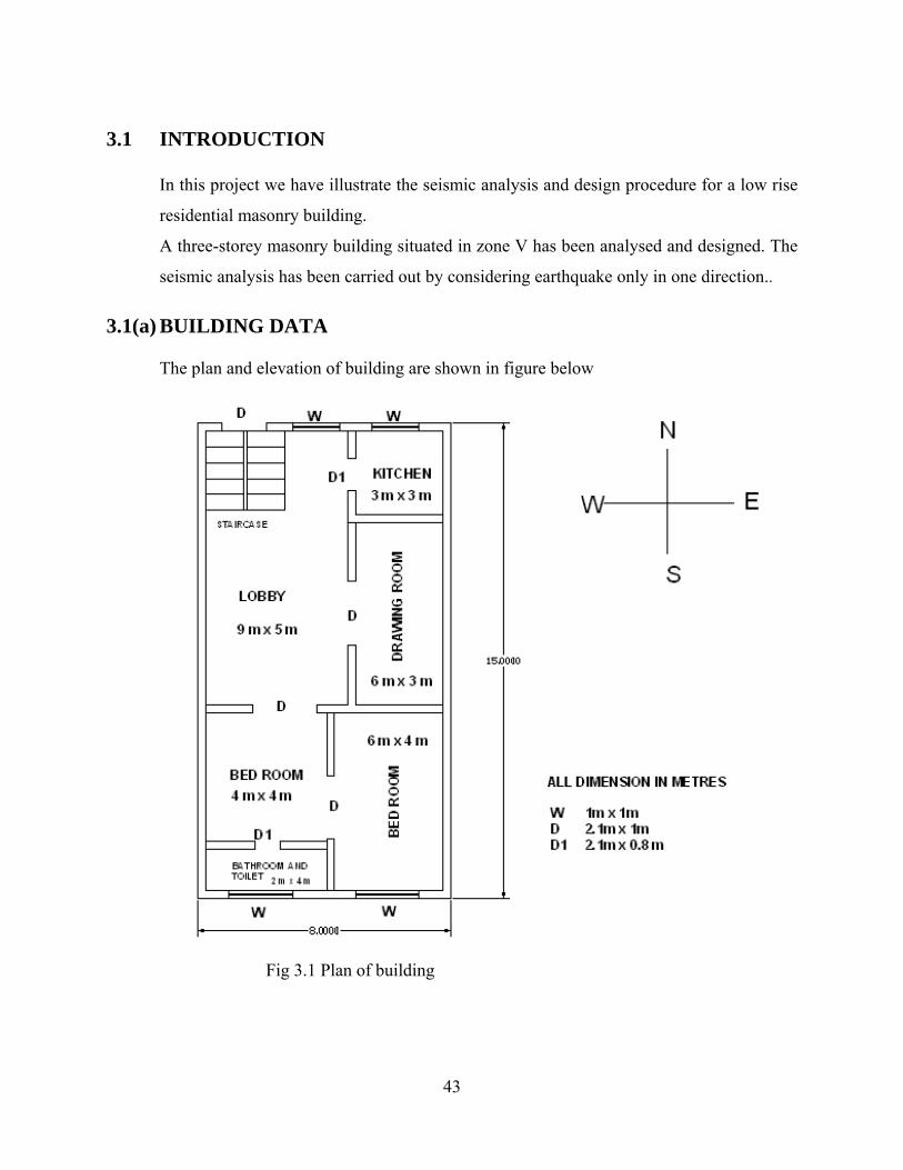
3.1 INTRODUCTION
In this project we have illustrate the seismic analysis and design procedure for a low rise
residential masonry building.
A three-storey masonry building situated in zone V has been analysed and designed. The
seismic analysis has been carried out by considering earthquake only in one direction.. 3.1(a) BUILDING DATA
The plan and elevation of building are shown in figure below
Fig 3.1 Plan of building

44
Fig3.2 North wall and south wall Elevation 3.1(b) MATERIAL STRENGTH 1. Permissible compressive strength (ƒm) =2.5 N/mm2
(Assuming unit strength =35MPa and mortar H1 type)
In code IS 4326:1993 specifies that well burnt bricks and solid concrete bricks possessing
a compressive / crushing strength not less than 35 MPa shall be used. The compressive
strength of unit may be defined as the maximum stress to which unit can be subjected by
a gradually increasing load applied in perpendicular direction either to bedding plane or
normal position. The mortar used I masonry constructions in seismic area depends upon
the design seismic coefficient. For (0.08 <An (seismic coefficient) <0.12) and (0.12< An,
0.05) type building H1 type mortar (cement: sand 1:4) is used.
2. Permissible stress in steel in tension =0.55 ƒy
(Use high deformed bar Fe415 i.e, ƒy =230 N/mm2)

45
3.1(c) LOADS
LIVE LOAD DATA Live Load on roof =1.0 KN/mm2 (for seismic calculation =0) Live Load on floor =1.0 KN/ mm2
DEAD LOAD DATA Thickness of floor and roof slab=120 mm
Weight of slab =3 KN/ mm2
(Assuming weight density of concrete =25 KN/ mm3)
Thickness of wall =250 mm
Weight of wall =5 KN/ m2
(Assuming weight density of masonry = 20 KN/ m3 )
3.1(d) SEISMIC DATA: (as per IS 1893 (part 1):2002 (i) Seismic zone = zone V
(ii) Zone factor (Z) =0.36, Zone factor given is for maximum considered Earthquake ( MCE)
and service Life of structure in a zone. The factor 2 is used so as reduce the Maximum
considered Earthquake (MCE) zone factor to the factor for design basis Earthquake
(Table 2 )
(iii) Importance factor ( I) =1
(iv) Response Reduction Factor =3
The value of R for building is given in Table 7: IS 1893 (Part 1); 2002.
(v) Soil medium type, for which average response acceleration coefficient are as
Sa/g= { 1+15T, 0.00<= T<=0.10
2.50, 0.10<=T<=0.55
1.36/T, 0.55<=T<=4.00}
(v) Direction of seismic force = E- W Direction.

46
3.2 STEP 1: DETERMINATION OF DESIGN LATERAL
EARTHQUAKE FORCES
For determination of Lateral Load earthquake “Equivalent Static Lateral forces Procedure
“is adopted.
(i) SIESMIC WEIGHT CALCULATIONS:
The seismic weight of each floor is its full dead Load plus appropriate amount of
imposed Load. While computing the seismic weight of each floor, the weight of columns
and walls in any storey shall be equally distributed to the floors above & below the
storey. The weight of Live Load for seismic calculation is taken as zero.
Seismic weight calculations
Description: Load Calculations Total
DL and LL load at roof level
(i) Weight of roof 3×8×15 360 KN
(ii) Weight of walls
(Assuming half weight of walls ½ {2(8+15) ×4×5} 460 KN
at second storey is lumped at roof)
(iii) Weight of live load (LL) (for seismic
Calculation, LL on Roof is zero) 0×8×15 0 KN
(Wr) weight at roof level (i) + (ii) + (iii) 360+460+0 820 KN
47
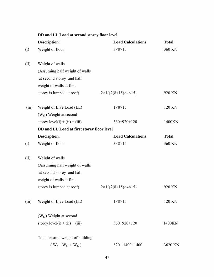
DD and LL Load at second storey floor level
Description: Load Calculations Total
(i) Weight of floor 3×8×15 360 KN
(ii) Weight of walls
(Assuming half weight of walls
at second storey and half
weight of walls at first
storey is lumped at roof) 2×1/{2(8+15)×4×15} 920 KN
(iii) Weight of Live Load (LL) 1×8×15 120 KN
(Wf1) Weight at second
storey level(i) + (ii) + (iii) 360+920+120 1400KN
DD and LL Load at first storey floor level
Description: Load Calculations Total
(i) Weight of floor 3×8×15 360 KN
(ii) Weight of walls
(Assuming half weight of walls
at second storey and half
weight of walls at first
storey is lumped at roof) 2×1/{2(8+15)×4×15} 920 KN
(iii) Weight of Live Load (LL) 1×8×15 120 KN
(Wf2) Weight at second
storey level(i) + (ii) + (iii) 360+920+120 1400KN
Total seismic weight of building
( Wr + Wf1 + Wf2 ) 820 +1400+1400 3620 KN

48
(ii) Time period calculations
The approximate fundamental natural period of a masonry building can be calculated
from the clause 7.6.2 of IS 1893(Part 1):2002 as,
Ta = 0.09 h/√d
Where,
h= height of building in m, {i.e, 4.0 (first storey) +4.0 (second storey)+4.0 (third storey)
= 12.0 m}
d= base dimension of building at the plinth level, in m, along the considered direction of
lateral force (i.e, 8 m assuming earthquake in E-W direction)
Ta = 0.09 x12/√8 = 0.038 sec
Sa/g =2.5, for T=0.038
Ah = (ZI Sa)/ (2Rg) = (0.36/2) (1/3) (2.5) =0.15
The total design lateral base shear (VB) along the direction of motion is given by
VB =AhW=0.15 x 3620=543 KN
iii) Vertical distribution of Base Shear to different floor levels:
The design Lateral base shear (VB) computed shall be distributed along the height of
building as per the following expression:
Qi= VB Wihi2/ ( nΣi=1 Wihi
2)
Qi= design lateral force at floor I,
Wi=seismic weight of floor I,
hi= height of floor i measured from base
n= number of storeys in the building is the number of levels at which mass are located.
Lateral Force at roof level
= VB Wihi2/ ( nΣi=1 Wihi
2)
= (543x820x122) / (820x122+1400x82 +1400x42)
= 278.87 KN
Lateral force at 2nd storey roof roof level
= VB Wihi2/ ( nΣi=1 Wihi
2)
49
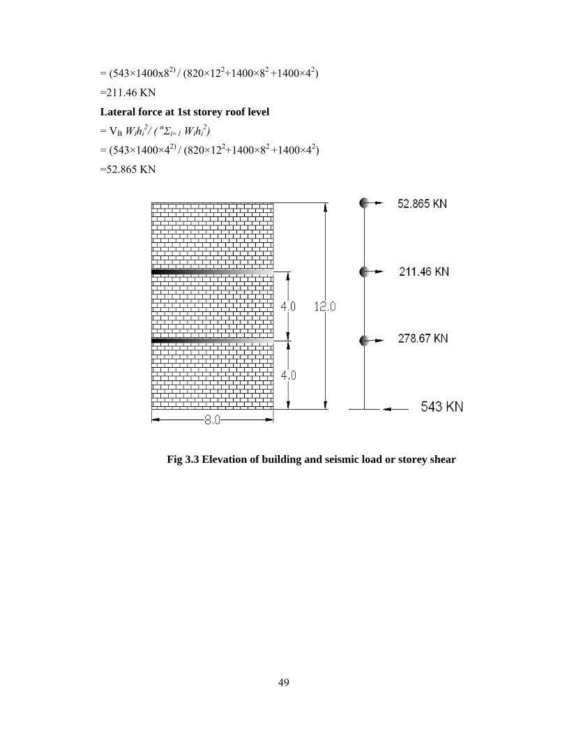
= (543×1400x82) / (820×122+1400×82 +1400×42)
=211.46 KN
Lateral force at 1st storey roof level
= VB Wihi2/ ( nΣi=1 Wihi
2)
= (543×1400×42) / (820×122+1400×82 +1400×42)
=52.865 KN
Fig 3.3 Elevation of building and seismic load or storey shear
50
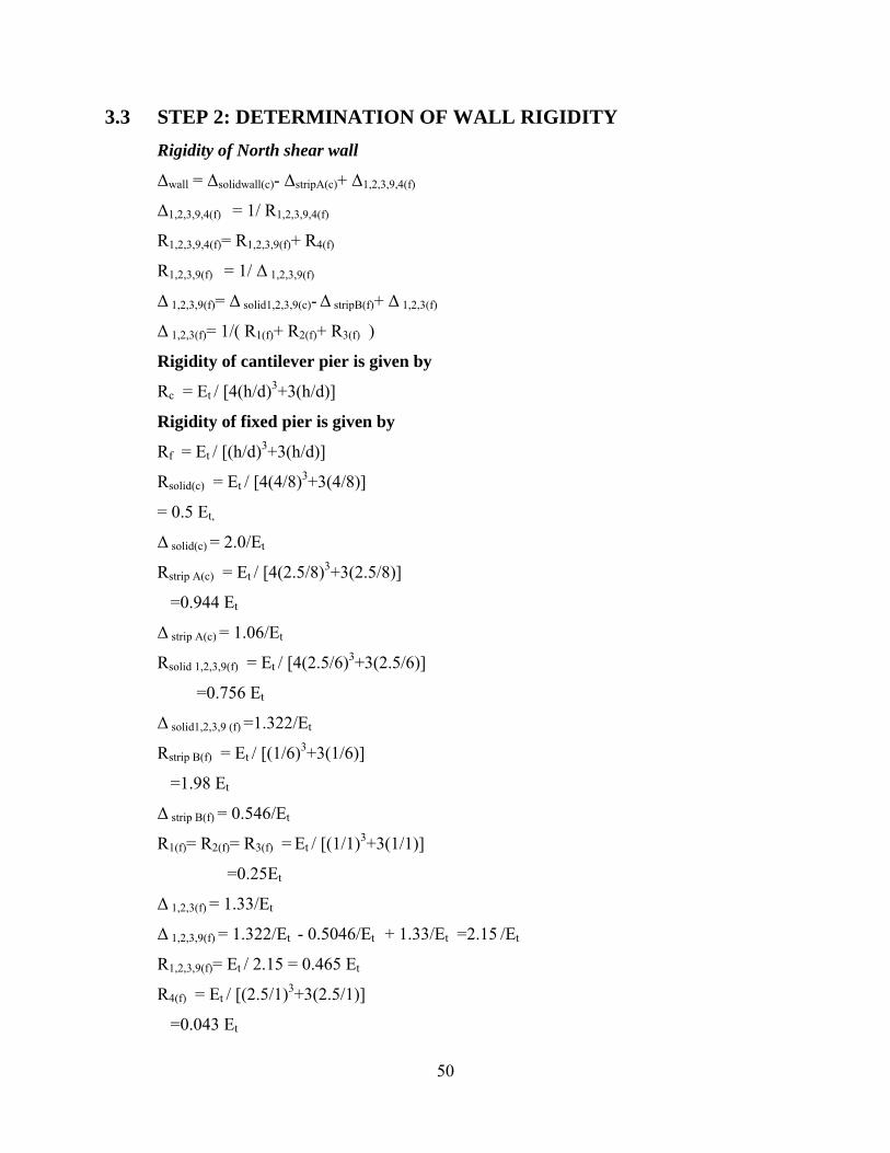
3.3 STEP 2: DETERMINATION OF WALL RIGIDITY Rigidity of North shear wall
∆wall = ∆solidwall(c)- ∆stripA(c)+ ∆1,2,3,9,4(f)
∆1,2,3,9,4(f) = 1/ R1,2,3,9,4(f)
R1,2,3,9,4(f)= R1,2,3,9(f)+ R4(f)
R1,2,3,9(f) = 1/ ∆ 1,2,3,9(f)
∆ 1,2,3,9(f)= ∆ solid1,2,3,9(c)- ∆ stripB(f)+ ∆ 1,2,3(f)
∆ 1,2,3(f)= 1/( R1(f)+ R2(f)+ R3(f) )
Rigidity of cantilever pier is given by
Rc = Et / [4(h/d)3+3(h/d)]
Rigidity of fixed pier is given by
Rf = Et / [(h/d)3+3(h/d)]
Rsolid(c) = Et / [4(4/8)3+3(4/8)]
= 0.5 Et,
∆ solid(c) = 2.0/Et
Rstrip A(c) = Et / [4(2.5/8)3+3(2.5/8)]
=0.944 Et
∆ strip A(c) = 1.06/Et
Rsolid 1,2,3,9(f) = Et / [4(2.5/6)3+3(2.5/6)]
=0.756 Et
∆ solid1,2,3,9 (f) =1.322/Et
Rstrip B(f) = Et / [(1/6)3+3(1/6)]
=1.98 Et
∆ strip B(f) = 0.546/Et
R1(f)= R2(f)= R3(f) = Et / [(1/1)3+3(1/1)]
=0.25Et
∆ 1,2,3(f) = 1.33/Et
∆ 1,2,3,9(f) = 1.322/Et - 0.5046/Et + 1.33/Et =2.15 /Et
R1,2,3,9(f)= Et / 2.15 = 0.465 Et
R4(f) = Et / [(2.5/1)3+3(2.5/1)]
=0.043 Et

51
∆ 1,2,39,4(f) = 1.968/Et
∆ wall = 2.0/Et - 1.06/Et + 1.96/Et =2.908 /Et
Rwall= 0.343Et
Rigidity of South shear wall
∆wall = ∆solidwall(c)- ∆stripA2(c)+ ∆5,6,7(f)
∆5,6,7(f) = 1/ R5,6,7(f)
R5,6,7(f)= R5(f)+ R6(f) + R7(f)
R5(f) = R7(f)=Et / [(1/1)3+3(1/1)]
= 0.25 Et,
R6(f) =Et / [(1/2)3+3(1/2)]
= 0.615 Et,
R5,6,7(f)=2x0.25 Et + 0.615 Et
= 1.115 Et,
∆ 5,6,7(f) = 1/ R5,6,7(f)
= 0.896/Et,
Rsolid(c) = Et / [4(4/8)3+3(4/8)]
= 0.5 Et, ∆ solid(c) = 2.0/Et
Rstrip A(c) = Et / [4(1/8)3+3(1/8)]
=2.612 Et
∆ solidA2 (c) =0.382/Et
∆ wall= ∆ solid wall (c) - ∆ solidA2 (c) +∆ 5,6,7 (f)
=2/Et - 0.382/Et + 0.896/Et
=2.513 /Et
Rwall = 0.398Et
Relative stiffness of walls
North shear wall =0.343/ (0.343+0.398) =0.462
South shear wall =0.398/ (0.343+0.398) =0.538
52
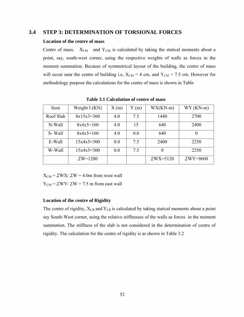
3.4 STEP 3: DETERMINATION OF TORSIONAL FORCES Location of the centre of mass
Centre of mass, XCM and YCM, is calculated by taking the statical moments about a
point, say, south-west corner, using the respective weights of walls as forces in the
moment summation. Because of symmetrical layout of the building, the centre of mass
will occur near the centre of building i.e, XCM = 4 cm, and YCM = 7.5 cm. However for
methodology purpose the calculations for the centre of mass is shown in Table
Table 3.1 Calculation of centre of mass
Item Weight I (KN) X (m) Y (m) WX(KN-m) WY (KN-m)
Roof Slab 8x15x3=360 4.0 7.5 1440 2700
N-Wall 8x4x5=160 4.0 15 640 2400
S- Wall 8x4x5=160 4.0 0.0 640 0
E-Wall 15x4x5=300 8.0 7.5 2400 2250
W-Wall 15x4x5=300 0.0 7.5 0 2250
ΣW=1280 ΣWX=5120 ΣWY=9600
XCM = ΣWX/ ΣW = 4.0m from west wall
YCM = ΣWY/ ΣW = 7.5 m from east wall
Location of the centre of Rigidity
The centre of rigidity, XCR and YCR is calculated by taking statical moments about a point
say South-West corner, using the relative stiffnesses of the walls as forces in the moment
summation. The stiffness of the slab is not considered in the determination of centre of
rigidity. The calculation for the centre of rigidity is as shown in Table 3.2

53
Table 3.2 Calculation of centre of rigidity
ITEM Rx Ry X (m) Y (m) Y Rx X Ry
N-Wall 0.462 - - 15 6.93 -
S-Wall 0.538 - - 0.0 0 -
E-Wall - 0.50 8.0 - - 4.0
W-
Wall
- 0.50 0.0 - - 0.0
Σ Rx
=1.0
Σ Ry
=1.0
Σ Y Rx
=6.93
Σ X Ry
=4.0
XCR = Σ XRy / Σ Ry = 4.0 m from West wall
YCR =Σ YRx / Σ Rx= 6.93.m from South wall
Torsional Eccentricity
Torsional Eccentricity in y- direction:
Eccentricity between centre of mass and centre of rigidity
ey = 7.50 - 6.93 =0.57m
Adding minimum 5% accidental eccentricity
0.05x15=0.75m
Total eccentricity = 0.57 + 0.75 = 1.32 m
Torsional eccentricity in X- direction
Eccentricity between centre of mass and centre of rigidity
ex= 4.0 – 4.0 =0.00 m
Adding minimum 5% accidental eccentricity
0.05x8=0.40 m
Total eccentricity = 0.00 + 0.40 = 0.40 m
54
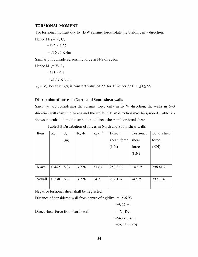
TORSIONAL MOMENT
The torsional moment due to E-W seismic force rotate the building in y direction.
Hence MTX= Vx Cy
= 543 × 1.32
= 716.76 KNm
Similarly if considered seismic force in N-S direction
Hence MTy= Vy Cx
=543 × 0.4
= 217.2 KN-m
Vy = Vx because Sa/g is constant value of 2.5 for Time period 0.11≤T≤.55
Distribution of forces in North and South shear walls
Since we are considering the seismic force only in E- W direction, the walls in N-S
direction will resist the forces and the walls in E-W direction may be ignored. Table 3.3
shows the calculation of distribution of direct shear and torsional shear.
Table 3.3 Distribution of forces in North and South shear walls
Item Rx dy
(m)
Rx dy Rx dy2 Direct
shear force
(KN)
Torsional
shear
force
(KN)
Total shear
force
(KN)
N-wall 0.462 8.07 3.728 31.67 250.866 +47.75 298.616
S-wall 0.538 6.93 3.728 24.3 292.134 -47.75 292.134
Negative torsional shear shall be neglected.
Distance of considered wall from centre of rigidity = 15-6.93
=8.07 m
Direct shear force from North-wall = Vx RN
=543 x 0.462
=250.866 KN

55
Direct shear force from South-wall = Vx Rs
=543×0.538
=292.134 KN
Torsional force in North-wall = (ΣRx dy )/ (ΣRx dy2) × (Vx ey)
= 3.728 /55.96 × 716.76
=47.75 KN
Table 3.4 Distribution of forces in East and West shear walls
Item Ry dx *
(m)
Ry
dx
Ry dx2 Direct
shear force
(KN)
Torsional
shear
force
(KN)
Total
shear
force
(KN)
E-
wall
0.5 11 5.5 60.5 271.5 -19.745 271.5
W-
wall
0.5 4 2
8
Total=68.5
271.5 -7.180 278.68
Distance of considered wall from centre of rigidity = (15 - 4) = 11 m
Direct shear force in East wall = Vy RE
=543 × 0.5
= 271.5 m
Direct shear force in West wall = Vy Rw
=543 x 0.5
= 271.5 m
Torsional force in West-wall = (ΣRy dx )/ (ΣRy dx2) × (Vy ex)
= 5.5 /60.5 x 217.2
=19.745 KN
Torsional force in West-wall = (ΣRy dx )/ (ΣRy dx2) × (Vy ex)
= 2 /60.5 x 217.2
=7.180 KN

56
DISTRIBUTION OF THE TOTAL SHEAR TO INDIVIDUAL PIERS WITHIN
THE WALL
The shear carried by the North and South shear walls is now distributed to individual
piers on the basis of their respective stiffness.
NORTH SHEAR WALL:
Shear 273.233 KN in pier group 1,23,9 is further subdivided in vertical piers 1, 2, 3 on
proportion to their stiffness. The stiffness of pier 1, 2, 3 is 0.25 each, so the shear force
carried by each pier is
Pier Stiffness Relative stiffness Shear force (KN)
1 0.25 0.33 273.233 × 0.33= 90.17
2 0.25 0.33 90.17
3 0.25 0.33 90.17
4 0.043 0.085 298.676 × 0.085 = 23.22
5 0.25 0.225 65.73
6 0.615 0.55 160.67
7 0.25 0.225 65.73
Pier Group stiffness Relative stiffness Shear force
1,2,3,9 0.465 0.915 273.233
Pier 4 0.043 0.085 2323
57
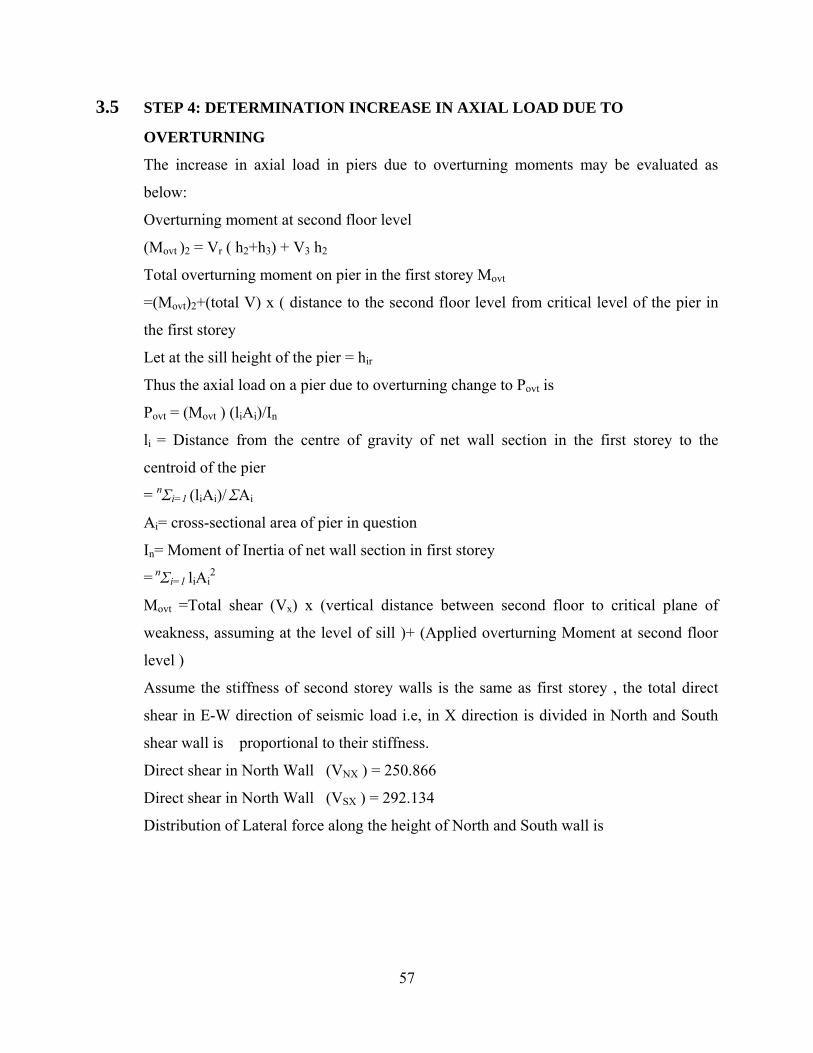
3.5 STEP 4: DETERMINATION INCREASE IN AXIAL LOAD DUE TO
OVERTURNING
The increase in axial load in piers due to overturning moments may be evaluated as
below:
Overturning moment at second floor level
(Movt )2 = Vr ( h2+h3) + V3 h2
Total overturning moment on pier in the first storey Movt
=(Movt)2+(total V) x ( distance to the second floor level from critical level of the pier in
the first storey
Let at the sill height of the pier = hir
Thus the axial load on a pier due to overturning change to Povt is
Povt = (Movt ) (liAi)/In
li = Distance from the centre of gravity of net wall section in the first storey to the
centroid of the pier
= nΣi=1 (liAi)/ ΣAi
Ai= cross-sectional area of pier in question
In= Moment of Inertia of net wall section in first storey
= nΣi=1 liAi2
Movt =Total shear (Vx) x (vertical distance between second floor to critical plane of
weakness, assuming at the level of sill )+ (Applied overturning Moment at second floor
level )
Assume the stiffness of second storey walls is the same as first storey , the total direct
shear in E-W direction of seismic load i.e, in X direction is divided in North and South
shear wall is proportional to their stiffness.
Direct shear in North Wall (VNX ) = 250.866
Direct shear in North Wall (VSX ) = 292.134
Distribution of Lateral force along the height of North and South wall is
58
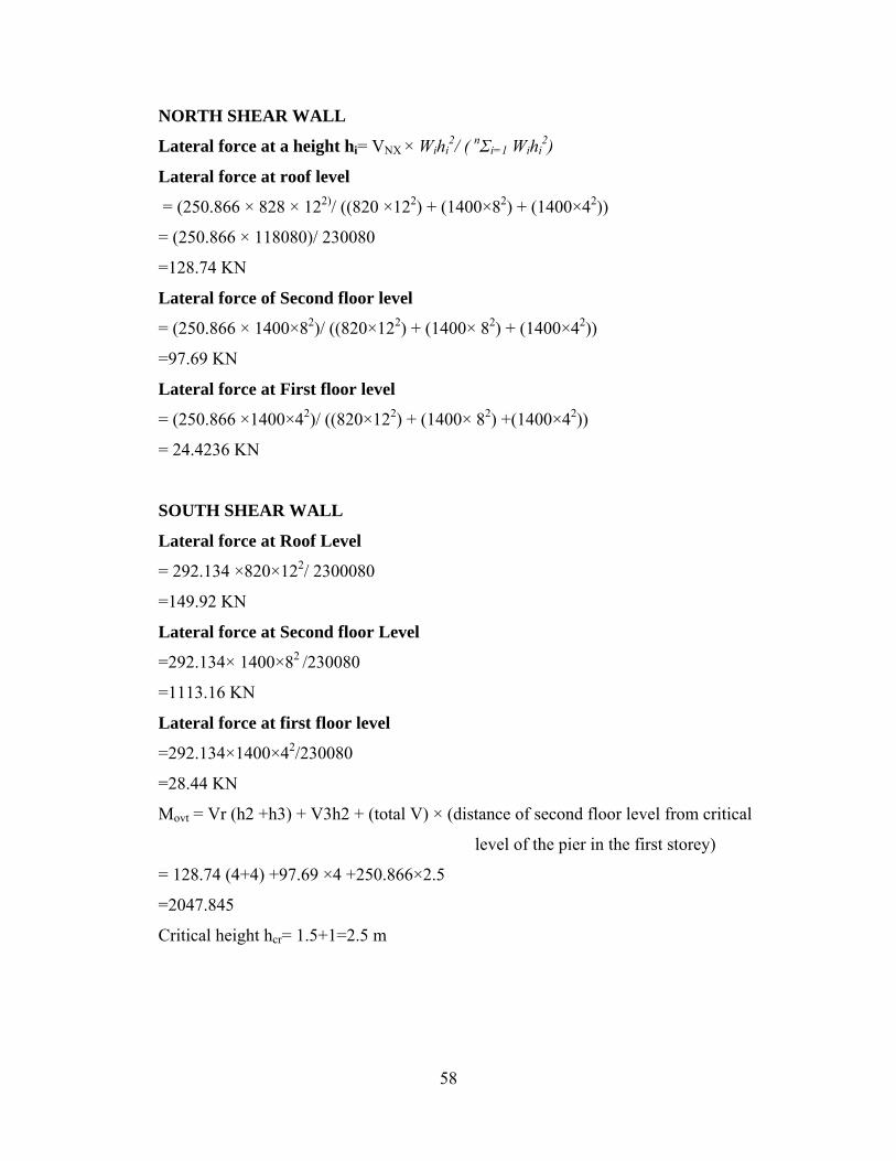
NORTH SHEAR WALL
Lateral force at a height hi= VNX × Wihi2/ ( nΣi=1 Wihi
2)
Lateral force at roof level
= (250.866 × 828 × 122)/ ((820 ×122) + (1400×82) + (1400×42))
= (250.866 × 118080)/ 230080
=128.74 KN
Lateral force of Second floor level
= (250.866 × 1400×82)/ ((820×122) + (1400× 82) + (1400×42))
=97.69 KN
Lateral force at First floor level
= (250.866 ×1400×42)/ ((820×122) + (1400× 82) +(1400×42))
= 24.4236 KN
SOUTH SHEAR WALL
Lateral force at Roof Level
= 292.134 ×820×122/ 2300080
=149.92 KN
Lateral force at Second floor Level
=292.134× 1400×82 /230080
=1113.16 KN
Lateral force at first floor level
=292.134×1400×42/230080
=28.44 KN
Movt = Vr (h2 +h3) + V3h2 + (total V) × (distance of second floor level from critical
level of the pier in the first storey)
= 128.74 (4+4) +97.69 ×4 +250.866×2.5
=2047.845
Critical height hcr= 1.5+1=2.5 m

59
Increase in axial Load due to overturning moment
Povt = Movt LiAi /In
Where liAi = centroid of net section of wall is calculated as shown in table 5.6
In = Moment of inertia of net section of wall is calculated as shown in table 5.7
Table 3.5 Calculation of Centroid of Net Section of north wall
Pier Area (Ai) m2 l ( distance from lift
edge of wall to
centroid of pier ) m
Ail(m3 )
1 1×0.25=0.25 0.5 0.125
2 1×0.25=0.25 3 0.750
3 1×0.25= 0.25 5.5 1.375
4 1×0.25=0.25 7.5 1.875
Σl =1.0 Σ Ail = 4.125
Distance from left edge to centroid of net section of wall
= 4.125/1 = 4.125 m
Table 3.6 Calculation of moment of Inertia of net section of north wall
Pier Ai m2 Ii (m) Ail(m3 ) Ail2
(m4 )
I= td3/12 In= I + Aili2
1 0.25 3.625 0.906 3.285 0.25×1/12=0.02 3.305
2 0.25 1.125 0.281 0.316 0.02 0.326
3 0.25 1.375 0.344 0.472 0.02 0.492
4 0.25 3.375 0.844 2.848 0.02 2.865
1 6.79 = 7 m4
Increase in axial load in individual piers of north wall is determined in table 3.7

60
Table 3.7 Increase in axial load in Individual piers of North wall
Pier Ail(m3 ) Povt = Movt LiAi /In
1 0.906 265.04
2 0.281 82.20
3 0.344 100.64
4 0.844 246.91
Increase in axial Load in piers of South Wall
Overturning moment in South wall Movt
= Total shear at third floor ×critical height (hcr) + Movt(2)
=292.134 ×2.5 + 149.92 (4+4) + 113.76×4
=2384.735 KNm
Increase in axial Load due to overturning moment
= Povt = Movt LiAi /In
Where liAi = centroid of net section of wall is calculated as shown in table 3.8
In = Moment of inertia of net section of wall is calculated as shown in table 3.9
Table 3.8 Calculation of Centroid of net section of south wall
Pier Area (Ai) m2 l ( distance from lift
edge of wall to
centroid of pier ) m
Ail(m3 )
5 1×0.25=0.25 0.5 0.125
6 2×0.25=0.5 4.0 2.00
7 1×0.25= 0.25 7.5 1.875
Σl =1.0 Σ Ail = 4
Distance from left edge to centroid = 4/1=4 m
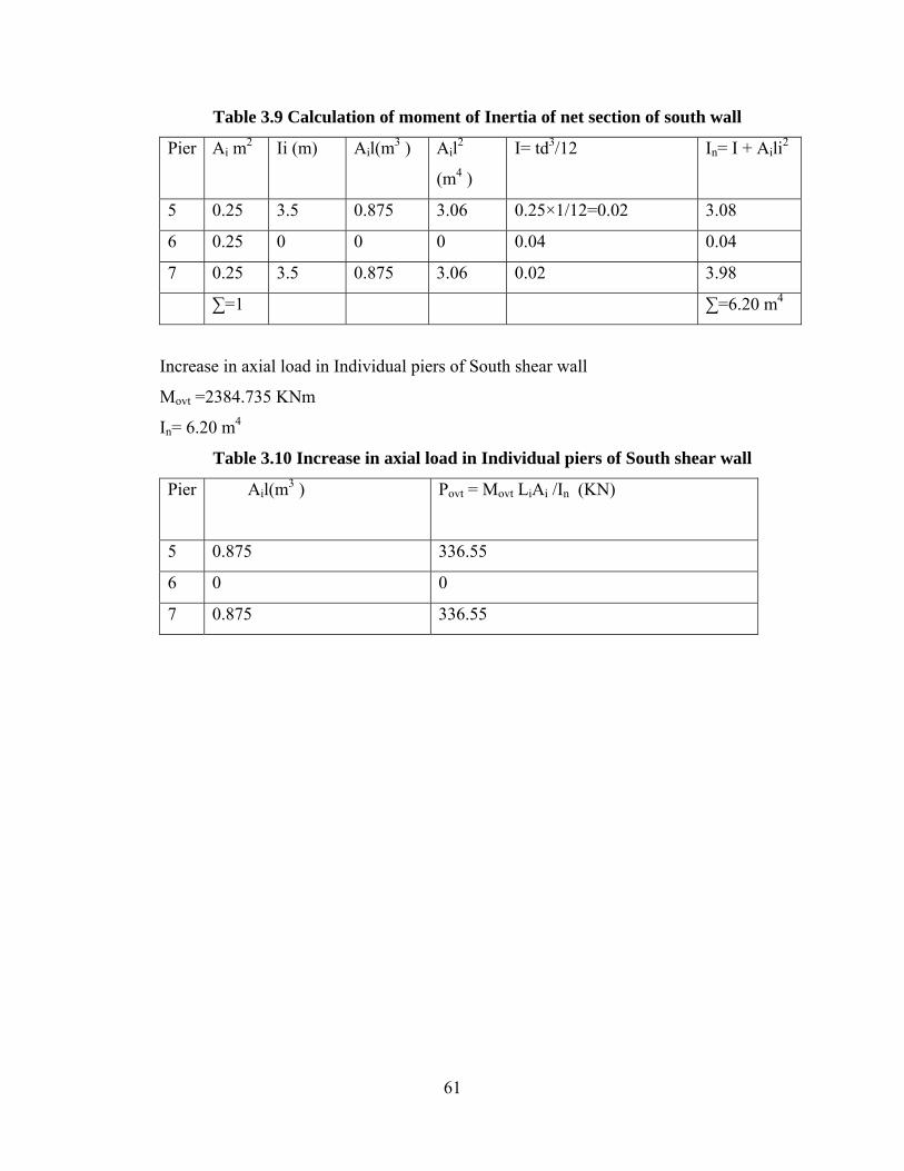
61
Table 3.9 Calculation of moment of Inertia of net section of south wall
Pier Ai m2 Ii (m) Ail(m3 ) Ail2
(m4 )
I= td3/12 In= I + Aili2
5 0.25 3.5 0.875 3.06 0.25×1/12=0.02 3.08
6 0.25 0 0 0 0.04 0.04
7 0.25 3.5 0.875 3.06 0.02 3.98
∑=1 ∑=6.20 m4
Increase in axial load in Individual piers of South shear wall
Movt =2384.735 KNm
In= 6.20 m4
Table 3.10 Increase in axial load in Individual piers of South shear wall
Pier Ail(m3 ) Povt = Movt LiAi /In (KN)
5 0.875 336.55
6 0 0
7 0.875 336.55
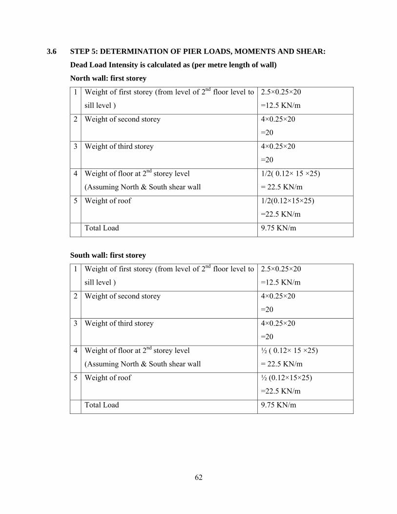
62
3.6 STEP 5: DETERMINATION OF PIER LOADS, MOMENTS AND SHEAR:
Dead Load Intensity is calculated as (per metre length of wall)
North wall: first storey
1 Weight of first storey (from level of 2nd floor level to
sill level )
2.5×0.25×20
=12.5 KN/m
2 Weight of second storey 4×0.25×20
=20
3 Weight of third storey 4×0.25×20
=20
4 Weight of floor at 2nd storey level
(Assuming North & South shear wall
1/2( 0.12× 15 ×25)
= 22.5 KN/m
5 Weight of roof 1/2(0.12×15×25)
=22.5 KN/m
Total Load 9.75 KN/m
South wall: first storey
1 Weight of first storey (from level of 2nd floor level to
sill level )
2.5×0.25×20
=12.5 KN/m
2 Weight of second storey 4×0.25×20
=20
3 Weight of third storey 4×0.25×20
=20
4 Weight of floor at 2nd storey level
(Assuming North & South shear wall
½ ( 0.12× 15 ×25)
= 22.5 KN/m
5 Weight of roof ½ (0.12×15×25)
=22.5 KN/m
Total Load 9.75 KN/m

63
Live Load Intensity (per metre length of wall) calculated as:
North wall: first storey
1 Live Load on floor (1 KN/m3)
( Assuming North and South shear wall will take
equal amount of load )
½(1×15)
=7.5 KN/m
2 Live Load on roof (1 KN/m3)
( Assuming North and South shear wall will take
equal amount of load )
½(1×15)
=7.5 KN/m
Total Load 15 KN/m
South wall: first storey
1 Live Load on floor (1 KN/m3)
( Assuming North and South shear wall will take
equal amount of load )
½(1×15)
=7.5 KN/m
2 Live Load on roof (1 KN/m3)
( Assuming North and South shear wall will take
equal amount of load )
½(1×15)
=7.5 KN/m
Total Load 15 KN/m
The total Axial Load (due to Dead Load, Live Load and overturning), shear and
moment in the individual parts of both the shear walls are calculated in Table 3.10 &
Table 3.11as below
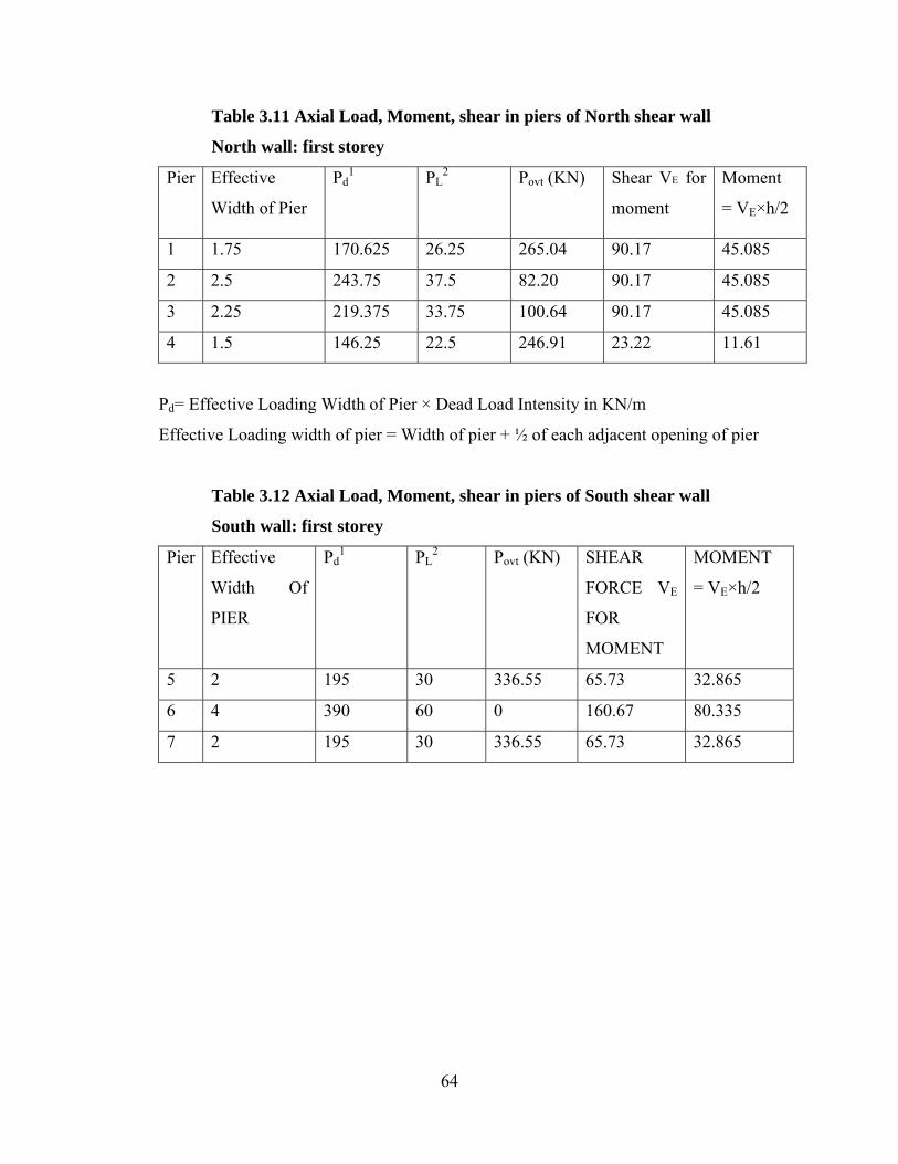
64
Table 3.11 Axial Load, Moment, shear in piers of North shear wall
North wall: first storey
Pier Effective
Width of Pier
Pd1 PL
2 Povt (KN) Shear VE for
moment
Moment
= VE×h/2
1 1.75 170.625 26.25 265.04 90.17 45.085
2 2.5 243.75 37.5 82.20 90.17 45.085
3 2.25 219.375 33.75 100.64 90.17 45.085
4 1.5 146.25 22.5 246.91 23.22 11.61
Pd= Effective Loading Width of Pier × Dead Load Intensity in KN/m
Effective Loading width of pier = Width of pier + ½ of each adjacent opening of pier
Table 3.12 Axial Load, Moment, shear in piers of South shear wall
South wall: first storey
Pier Effective
Width Of
PIER
Pd1 PL
2 Povt (KN) SHEAR
FORCE VE
FOR
MOMENT
MOMENT
= VE×h/2
5 2 195 30 336.55 65.73 32.865
6 4 390 60 0 160.67 80.335
7 2 195 30 336.55 65.73 32.865
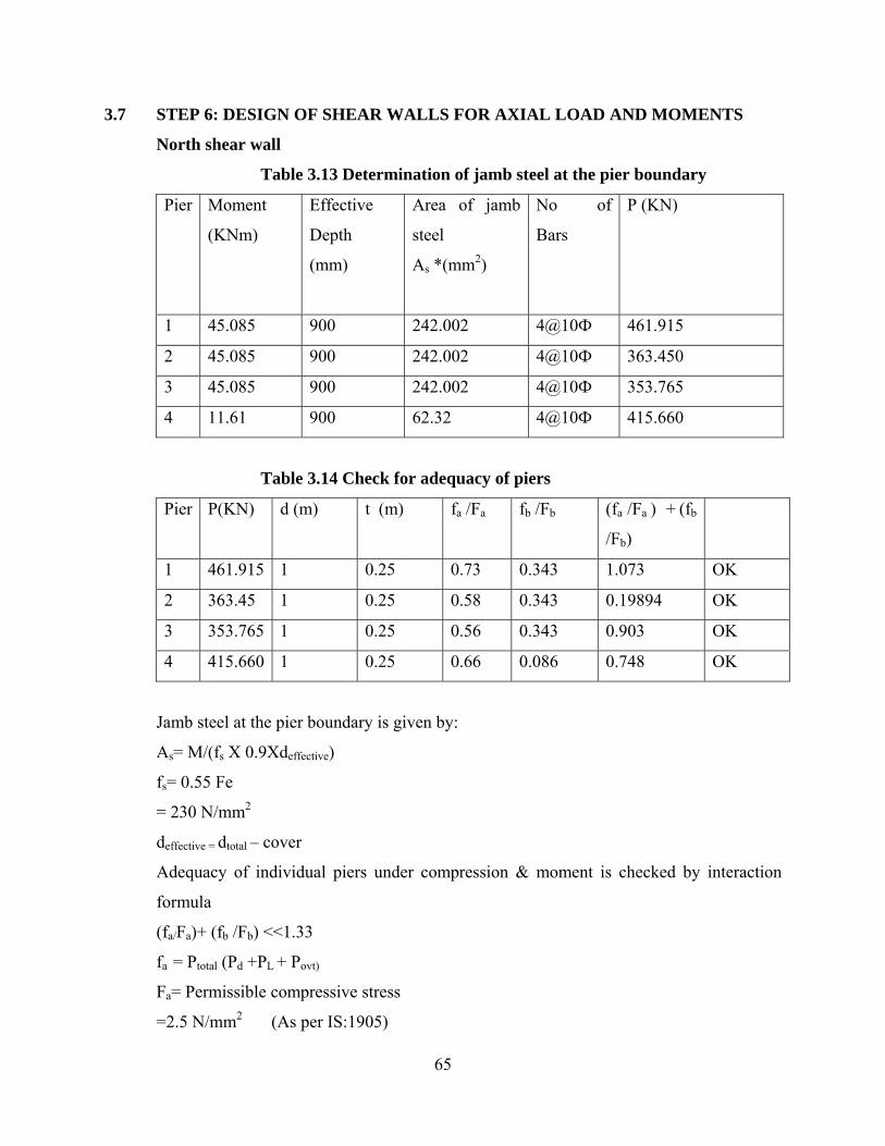
65
3.7 STEP 6: DESIGN OF SHEAR WALLS FOR AXIAL LOAD AND MOMENTS
North shear wall
Table 3.13 Determination of jamb steel at the pier boundary
Pier Moment
(KNm)
Effective
Depth
(mm)
Area of jamb
steel
As *(mm2)
No of
Bars
P (KN)
1 45.085 900 242.002 4@10Ф 461.915
2 45.085 900 242.002 4@10Ф 363.450
3 45.085 900 242.002 4@10Ф 353.765
4 11.61 900 62.32 4@10Ф 415.660
Table 3.14 Check for adequacy of piers
Pier P(KN) d (m) t (m) fa /Fa fb /Fb (fa /Fa ) + (fb
/Fb)
1 461.915 1 0.25 0.73 0.343 1.073 OK
2 363.45 1 0.25 0.58 0.343 0.19894 OK
3 353.765 1 0.25 0.56 0.343 0.903 OK
4 415.660 1 0.25 0.66 0.086 0.748 OK
Jamb steel at the pier boundary is given by:
As= M/(fs X 0.9Xdeffective)
fs= 0.55 Fe
= 230 N/mm2
deffective = dtotal – cover
Adequacy of individual piers under compression & moment is checked by interaction
formula
(fa/Fa)+ (fb /Fb) <<1.33
fa = Ptotal (Pd +PL + Povt)
Fa= Permissible compressive stress
=2.5 N/mm2 (As per IS:1905)
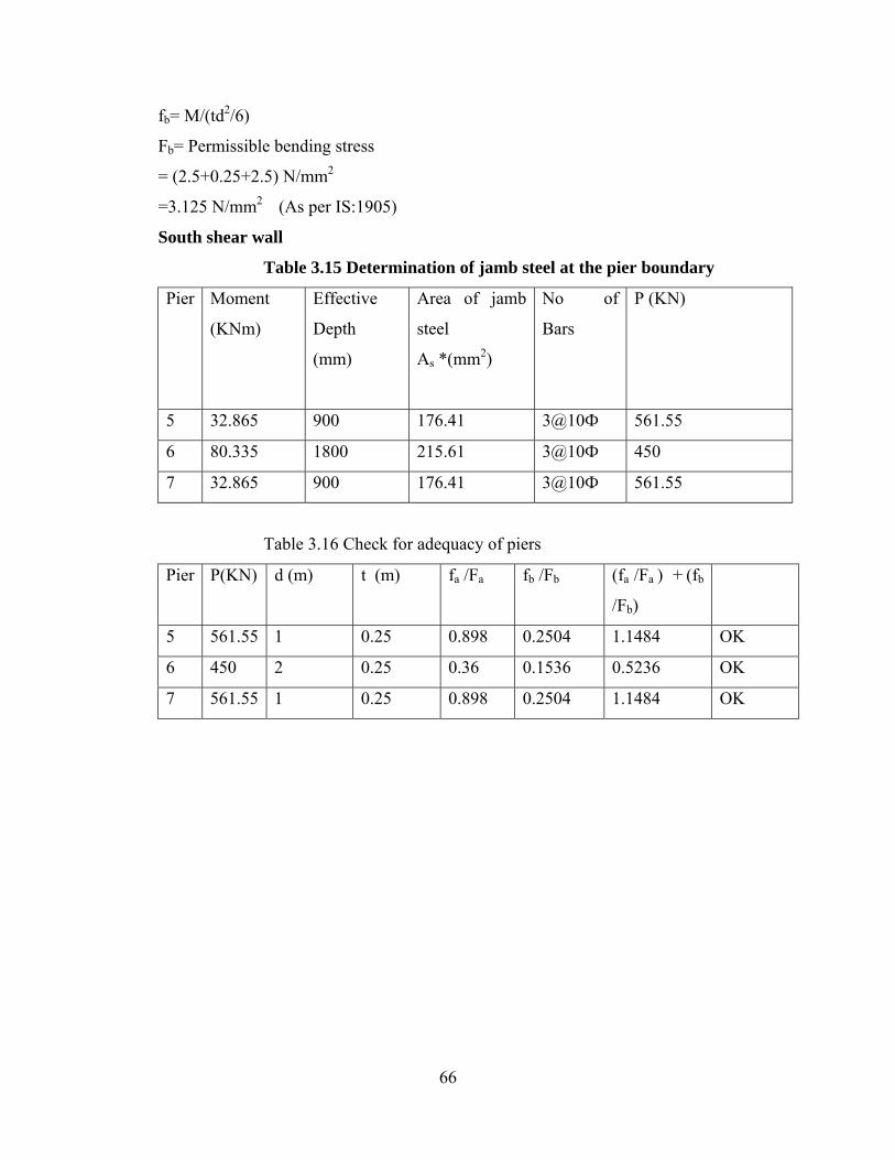
66
fb= M/(td2/6)
Fb= Permissible bending stress
= (2.5+0.25+2.5) N/mm2
=3.125 N/mm2 (As per IS:1905)
South shear wall
Table 3.15 Determination of jamb steel at the pier boundary
Pier Moment
(KNm)
Effective
Depth
(mm)
Area of jamb
steel
As *(mm2)
No of
Bars
P (KN)
5 32.865 900 176.41 3@10Ф 561.55
6 80.335 1800 215.61 3@10Ф 450
7 32.865 900 176.41 3@10Ф 561.55
Table 3.16 Check for adequacy of piers
Pier P(KN) d (m) t (m) fa /Fa fb /Fb (fa /Fa ) + (fb
/Fb)
5 561.55 1 0.25 0.898 0.2504 1.1484 OK
6 450 2 0.25 0.36 0.1536 0.5236 OK
7 561.55 1 0.25 0.898 0.2504 1.1484 OK
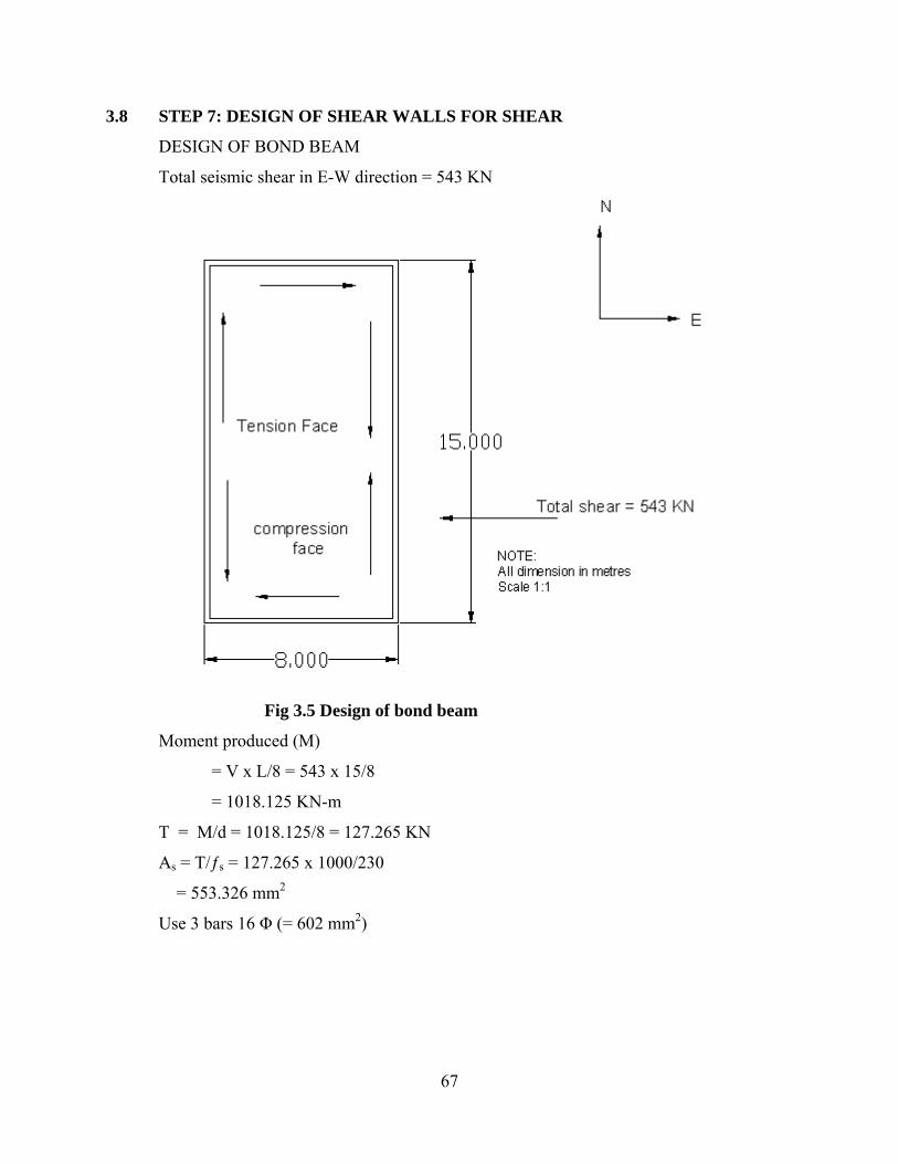
67
3.8 STEP 7: DESIGN OF SHEAR WALLS FOR SHEAR
DESIGN OF BOND BEAM
Total seismic shear in E-W direction = 543 KN
Fig 3.5 Design of bond beam
Moment produced (M)
= V x L/8 = 543 x 15/8
= 1018.125 KN-m
T = M/d = 1018.125/8 = 127.265 KN
As = T/ƒs = 127.265 x 1000/230
= 553.326 mm2
Use 3 bars 16 Φ (= 602 mm2)

68
3.9 STEP 8: STRUCTURAL DETAILS ([IS 4326:1993]3 & (Refer to Appendix 1.6, 1.7, 1.8, 1.9, 1.10, 1.11, 1.12)
1. The three storeyed residential building belongs to category C thus strengthening (a to g)
to be provided in all storeyes includes the following:
a) Masonry mortar
b) Lintel Band
c) Roof Band
d) Vertical Steel especially at corners and junctions of walls
e) Vertical steel at jambs of openings
f) Plinth band
g) Dowel Bars.
LINTEL BAND
It is a band provided at lintel level on all load bearing internal, external longitudinal and
cross walls. The band is made of reinforced concrete not leaner than M15, or reinforced
brickwork not leaner than 1:3.
ROOF BAND
It is band provided immediately below the roof or floors.
PLINTH BAND
It is a band provided at plinth level of walls on top of the foundation wall .This is to
provided where strip footings of masonry are used and the soil is either uneven in its
properties as frequently happens in hill tracts
The vertical thickness of RC Band is kept minimum of 150 mm. The longitudinal steel
bars are 4 No. of bars of diameter 12mm.The longitudinal steel bar is held in
position by steel links or stirrups 6mm diameter spaced at 150 mm apart.
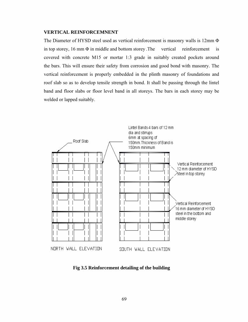
69
VERTICAL REINFORCEMNENT
The Diameter of HYSD steel used as vertical reinforcement is masonry walls is 12mm Φ
in top storey, 16 mm Φ in middle and bottom storey .The vertical reinforcement is
covered with concrete M15 or mortar 1:3 grade in suitably created pockets around
the bars. This will ensure their safety from corrosion and good bond with masonry. The
vertical reinforcement is properly embedded in the plinth masonry of foundations and
roof slab so as to develop tensile strength in bond. It shall be passing through the lintel
band and floor slabs or floor level band in all storeys. The bars in each storey may be
welded or lapped suitably.
Fig 3.5 Reinforcement detailing of the building

70
3.10 STAIRCASE DETAILS
In this work we have not done design of staircase. The staircase design should be done
separately. To avoid bracing /strut action, the staircase should be separated from the rest
of the building
Fig 3.6 Separated staircase
3.11 PARTITION WALLS The partition wall has not been considered in this design of this masonry building. The
partition wall increases the stiffness of the structure, thus by not considering its design we
have considered for the critical side and safe design

71
CONCLUSIONS
Masonry buildings are the most common type of construction used for all housing around
the world. But the post earthquake survey has proved that the masonry buildings are most
vulnerable to and have suffered maximum damages in the past earthquakes. A survey of
the affected areas in past earthquakes demonstrated that the major losses of lives were
due to collapse of low-strength masonry buildings. Due to the brittleness of the masonry
material, lack of ductility, strength and locally used traditional material in a
traditional manner without the earthquake-resistant features are the main causes of
collapse of building during earthquake.
The present work is a step towards with regard to illustrate a procedure for seismic
analysis and design of masonry building. The procedure has been presented by
considering each clause as mentioned in IS 1905 and IS 4326:1993 with the help of an
example of a three-storeyed residential masonry building.
CONCLUSION DRAWN:
1. The best shapes of earthquake resistant buildings are regular shapes and preferably with
two axes of symmetry. This ensures the centre of gravity and rigidity will be the same or
close to each other resulting in minimization of torsion moment in building.
2. Provision of bonds at different level increases the number of lateral force and thereby
reduces the effect of seismic forces remarkably.
3. Provision of vertical reinforcement in flexural walls helps to resist the moments
generated due to seismic force. This in turn helps in safe distribution of the lateral load to
the shear walls.
4. Provision of vertical reinforcement in shear walls increases the load carrying capacity and
the flexural strength of the wall.
5. Vertical steel at walls especially at corners, at openings of shear wall resists the
compression and flexure forces helps in preventing sliding or collapse of building.

72
6. A number of construction aspects are required to ensure the box action. Firstly,
connections between the walls should be good. This can be achieved by (a) ensuring
good interlocking of the masonry courses at the junctions, and (b) employing horizontal
hooks, at various levels, at intersection of the orthogonal walls.
7. The sizes of openings need to be kept small and preferably closer to the centre. The
smaller the opening the larger is the resistance offered by the wall.
8. Lastly, the tendency of a wall to topple when pushed in the weak direction can be
reduced by limiting its length-to-thickness and height-to-thickness ratio called the
slenderness ratio.

73
REFERENCES 1. EARTHQAUKE RESISTANT DESIGN OF STRUCTURES BY PANKAJ AGARWAL & MANISH SHRIKHANDE PRENTICE HALL OF INDIA, PRIVATE LIMITED
2. GUIDELINES FOR EARTHQUAKE RESISTANT BUILDINGS, NPEEE SHORT TERM COURSES ON EARTHQUAKE RESISTANT DESIGN OF RC BUILDINGS JULY 24-29, 2006 IIT ROORKEE
3. LEARNING EARTHQUAKE DESIGN AND CONSTRUCTION IITK-BMTPC 4. SCHNEIDER, R.R AND DICKEY, W.L.REINRCED MASONRY DESIGN,3R D ,PRENTICE HALL,NEW JERSEY,1994. 5. MIA, MASONRY CODE AND SPECIFICATION,A Co-PUBLICATION OF
MASONRY INSTITUTE OF AMERICA AND CRC PRESS,NEWYORK 1998.
6. IS 4326, 1993, INDIAN STANDARD CODE OF PRACTICE FOR EARTHQUAKE RESISTANT DESIGN AND CONSTRUCTION OF BUILDING (2N D REVISION).
7. IS 1893 (PART I), 2002, INDIAN STANDARD CRITERIA FOR EARTHQUAKE RESISTANT DESIGN OF STRUCTURES (5T H REVISION). 8. IS 1905: CODE OF STUCTURAL USE OF UNREINFORCED MASONRY (3R D REVISION) 9. APPENDIX A

74
APPENDIX A
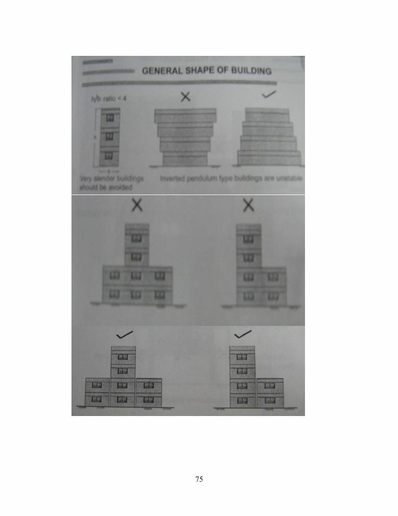
75
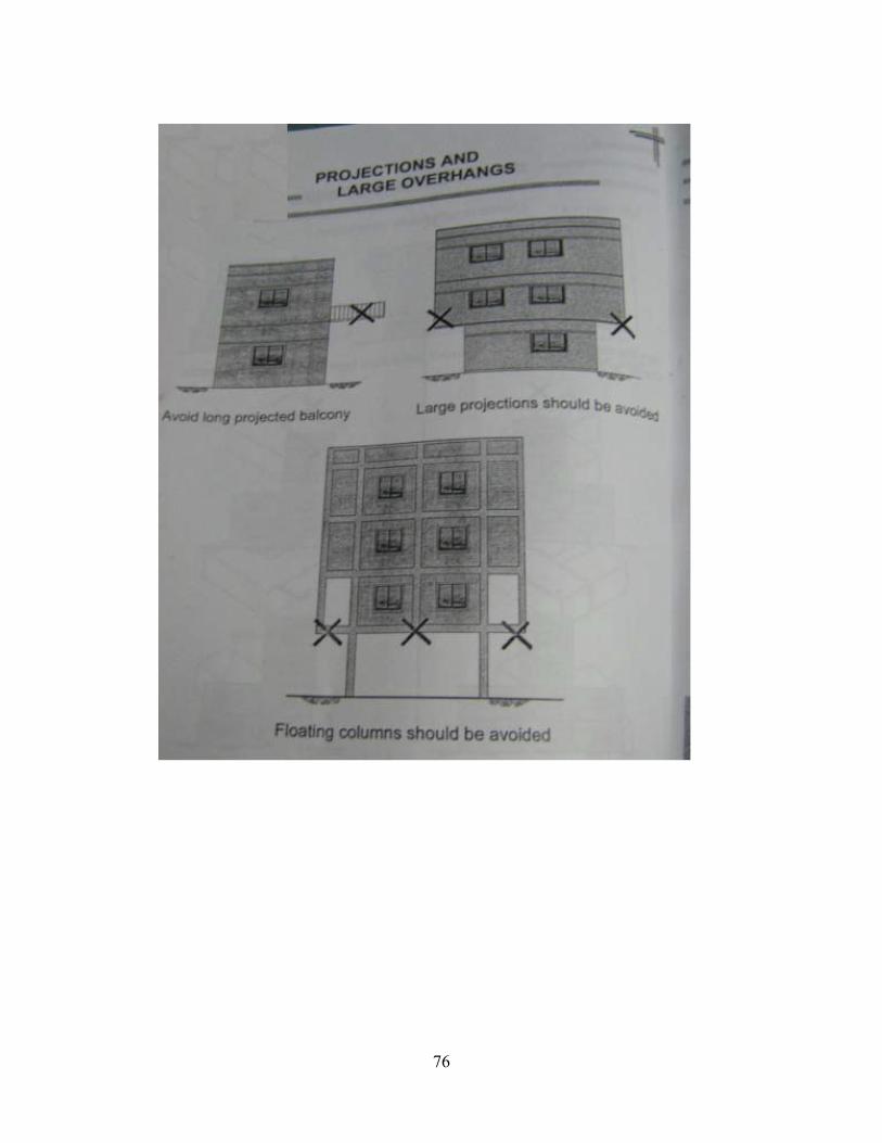
76

77

78

79
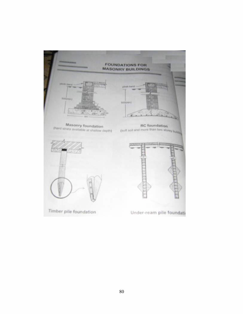
80

81

82

83

84
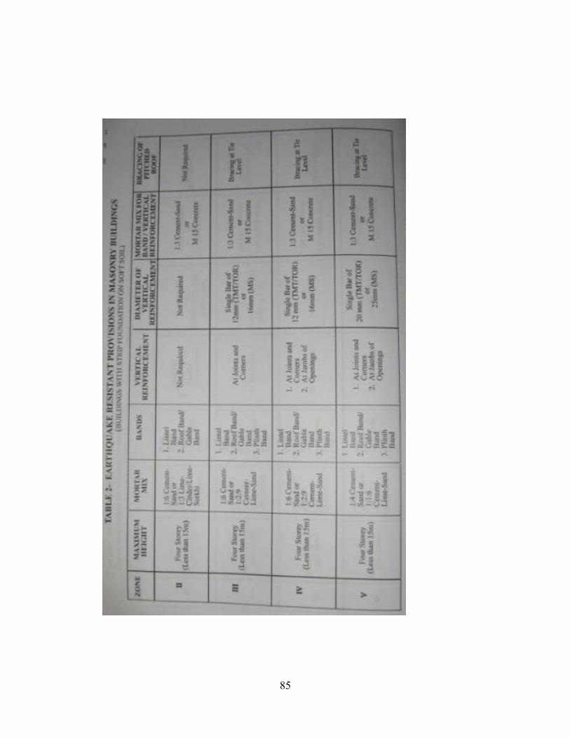
85

86

87