Analysis and Classification of Karakuri Technologies for ... · Karakuri technology is a Japan...
12
Analysis and Classification of Karakuri Technologies for Reinforcement of Their Visibility, Improvement and Transferability: An Attempt for Enhancing Lean Management Hiroshi Katayama 1 , Kenta Sawa 2 , Reakook Hwang 3 , Norio Ishiwatari 4 and Nobuyuki Hayashi 4 1 Faculty of Science and Engineering, Waseda University, Tokyo, Japan 2 Department of Industrial and Management Systems Engineering, School of Creative Science and Engineering, Waseda University, Tokyo, Japan 3 Samsung Economic Research Institute, Seoul, Korea 4 Sankyu Inc., Tokyo, Japan, Japan Abstract--Karakuri technology, a member technology of lean management, is a unique method that aims to contribute environmental and labour issues by utilizing natural physical phenomena and related useful elemental mechanisms. Recent years, their developed works and application tend to become black box-like due to maniac development as well as technology advancement. Recognizing this situation, this paper proposes to utilize a template procedure for effective analysis and improvement of this technology for successful knowledge transfer among experts and beginners. Also, aiming to extract useful information on further development and improvement, it analyses the relations among various elements of this technology by statistical quantification model. An example application is also given for demonstrating relevance of obtained information. I. INTRODUCTION Lean Management is well-known strategic management method and concept born in Japan[17] and globally propagated by US experts[18]. This management system consists of various module technologies and tools[10][11][14] with durable concept that enables to transfer it among industries and nations. All of these intend to contribute organizational performance and amount of evidence are accumulated in many companies, which are operating under this scheme. Within the module technologies, Karakuri technology is a Japan unique method, which aims to utilize natural physical phenomena, such as gravity force, wind, electromagnetic power etc. and elemental mechanisms, such as lever, link (force transmission), pulley mechanisms etc[16]. Distinctive merit of this technology is enabling environment friendly operations, i.e. energy-saving, work-load mitigation, operational simplification etc. and number of useful case works have been developed and/or under-developing by many professionals as well as researchers. However, it tends to be quite sophisticated and complicated these years due to maniac development and technology advancement. Eventually, it became black-box like technology even for expert production engineers and most of young generation engineers have been isolated from it. To recover such hopeless situation, it is urgent to provide a comprehensive system to develop and improve this technology for the people who will succeed this asset. Based on this understanding, this paper aims to clarify structural elements and the way to construct Karakuri contrivances through analysis of various cases offered by industry-side. This approach and information being organized might contribute knowledge transfer of this technology among manufacturing engineers and managers. To perform effective analysis, relations among attributes of each Karakuri case, namely the objectives, its functions provided, utilized essential mechanisms and elementary contributors (natural phenomena, law in physics etc.) are intended to categorize and useful information for its reinforcement, e.g. what kind of elementary contributors are chartered for successful construction of specific essential mechanism, is anticipated to extract in terms of proximity data among aforementioned attributes. This analysis is performed based on the template procedure proposed in our past research[8]. Especially, for the latter proximity issue, a statistical quantification model[1] with its extension[12] is considered to apply. Then, some application example will be developed as case study for validation of our proposal. Contents of this paper include outline of the template procedure, some introductory explanation on Karakuri cases that have been collected from companies keen on this technology[4], example applications for analysis of their mechanisms and finally, demonstration of revised mechanism for further improvement of operational performance. All of these might contribute successful knowledge transfer on the related technology among experts and beginners. II. BACKGROUND OF THIS STUDY In this section, situation surrounding Karakuri technology including various efforts by industries and past research, is summarized. Distinctive activity that must be mentioned is Karakuri Exhibition[4][5][6] managed by Japan Institute of Plant Maintenance (JIPM), which was launched in 1993. This event has been held every year in Tokyo and Nagoya alternatively and, before the launch of this event, long-term, deep and substantial experience have been accumulated among driving industries such as car assemblers and parts suppliers[3][9][13][15]. Looking at academic research contributions, there are very 1895 2014 Proceedings of PICMET '14: Infrastructure and Service Integration.
Transcript of Analysis and Classification of Karakuri Technologies for ... · Karakuri technology is a Japan...
Analysis and Classification of Karakuri Technologies for Reinforcement of Their Visibility, Improvement and Transferability:
An Attempt for Enhancing Lean Management
Hiroshi Katayama1, Kenta Sawa2, Reakook Hwang3, Norio Ishiwatari4 and Nobuyuki Hayashi4
1Faculty of Science and Engineering, Waseda University, Tokyo, Japan 2Department of Industrial and Management Systems Engineering,
School of Creative Science and Engineering, Waseda University, Tokyo, Japan 3Samsung Economic Research Institute, Seoul, Korea
4Sankyu Inc., Tokyo, Japan, Japan Abstract--Karakuri technology, a member technology of lean
management, is a unique method that aims to contribute environmental and labour issues by utilizing natural physical phenomena and related useful elemental mechanisms. Recent years, their developed works and application tend to become black box-like due to maniac development as well as technology advancement. Recognizing this situation, this paper proposes to utilize a template procedure for effective analysis and improvement of this technology for successful knowledge transfer among experts and beginners. Also, aiming to extract useful information on further development and improvement, it analyses the relations among various elements of this technology by statistical quantification model. An example application is also given for demonstrating relevance of obtained information.
I. INTRODUCTION
Lean Management is well-known strategic management method and concept born in Japan[17] and globally propagated by US experts[18]. This management system consists of various module technologies and tools[10][11][14] with durable concept that enables to transfer it among industries and nations. All of these intend to contribute organizational performance and amount of evidence are accumulated in many companies, which are operating under this scheme. Within the module technologies, Karakuri technology is a Japan unique method, which aims to utilize natural physical phenomena, such as gravity force, wind, electromagnetic power etc. and elemental mechanisms, such as lever, link (force transmission), pulley mechanisms etc[16]. Distinctive merit of this technology is enabling environment friendly operations, i.e. energy-saving, work-load mitigation, operational simplification etc. and number of useful case works have been developed and/or under-developing by many professionals as well as researchers.
However, it tends to be quite sophisticated and complicated these years due to maniac development and technology advancement. Eventually, it became black-box like technology even for expert production engineers and most of young generation engineers have been isolated from it. To recover such hopeless situation, it is urgent to provide a comprehensive system to develop and improve this technology for the people who will succeed this asset. Based
on this understanding, this paper aims to clarify structural elements and the way to construct Karakuri contrivances through analysis of various cases offered by industry-side. This approach and information being organized might contribute knowledge transfer of this technology among manufacturing engineers and managers.
To perform effective analysis, relations among attributes of each Karakuri case, namely the objectives, its functions provided, utilized essential mechanisms and elementary contributors (natural phenomena, law in physics etc.) are intended to categorize and useful information for its reinforcement, e.g. what kind of elementary contributors are chartered for successful construction of specific essential mechanism, is anticipated to extract in terms of proximity data among aforementioned attributes. This analysis is performed based on the template procedure proposed in our past research[8]. Especially, for the latter proximity issue, a statistical quantification model[1] with its extension[12] is considered to apply. Then, some application example will be developed as case study for validation of our proposal.
Contents of this paper include outline of the template procedure, some introductory explanation on Karakuri cases that have been collected from companies keen on this technology[4], example applications for analysis of their mechanisms and finally, demonstration of revised mechanism for further improvement of operational performance. All of these might contribute successful knowledge transfer on the related technology among experts and beginners.
II. BACKGROUND OF THIS STUDY
In this section, situation surrounding Karakuri technology including various efforts by industries and past research, is summarized. Distinctive activity that must be mentioned is Karakuri Exhibition[4][5][6] managed by Japan Institute of Plant Maintenance (JIPM), which was launched in 1993. This event has been held every year in Tokyo and Nagoya alternatively and, before the launch of this event, long-term, deep and substantial experience have been accumulated among driving industries such as car assemblers and parts suppliers[3][9][13][15].
Looking at academic research contributions, there are very
1895
2014 Proceedings of PICMET '14: Infrastructure and Service Integration.
few numbers of papers on this subject. Therefore, international conference is a quite important vehicle in the meaning of knowledge sharing and transfer especially on this subject. One typical contribution in the past is on proposal of template procedure for Karakuri analysis[8], which aim to provide a weapon for easy understanding of essential mechanisms of Karakuri cases developed by experts. This template consists of 15 critical attribute issues which must be described in the specific format sheet through investigation. Specification of this template is given below. 1. Title of Improvement Project: Automatic Return of Trays
(Example) 2. Company Name: Company A (Example) 3. Nickname of the Case: B (Example) 4. Objective Operation: Parts Transportation and Automatic
Return Operation of Trays (Example) 5. Feature: Variety of Parts Shape and Weight, Automatic
Transportation of Heavy Parts (Example) 6. Overall Structure of Karakuri Contrivance: (Example)
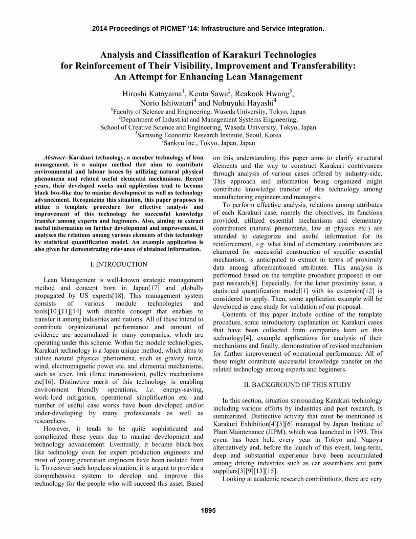
Fig. 1 and 2 illustrate overview of the equipment and essential structure of Karakuri mechanism which are provided by the company and drown by our laboratory respectively.
7. State Definition of Karakuri Contrivance: (Example) Table 1 is for the definition of the elements and their states of Karakuri mechanism.
Critical issues for creating this table are to identify
composed elements of Karakuri and to define the possible states of each element.
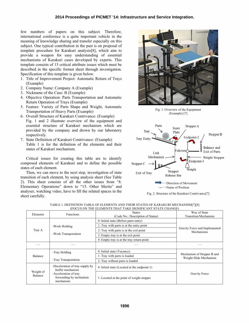
Then, we can move to the next step, investigation of state transition of each element, by using analysis sheet (See Table 2). This sheet consists of all the other issues from “8. Elementary Operations” down to “15. Other Merits” and analyser, watching video, have to fill the related spaces in the sheet carefully.
Fig. 1. Overview of the Equipment (Example) [7]
Fig. 2. Structure of the Karakuri Contrivance[7]
TABLE 1. DEFINITION TABLE OF ELEMENTS AND THEIR STATES OF KARAKURI MECHANISM[7][8]
(FOCUS ON THE ELEMENTS THAT TAKE SIGNIFICANT STATE CHANGE)
Elements Functions States (Code No.: Description of Status)
Way of State Transition/Mechanism
Tray A -Work Holding
-Work Transportation
0:Initial state (Before parts entry)
Gravity Force and Implemented Mechanisms
1:Tray with parts is at the entry point 2:Tray with parts is at the exit point 3:Empty tray is at the exit point 4:Empty tray is at the tray return point
…. …. …. ….
Balance -Tray Holding -Tray Transportation
0:Initial state (Vacancy) Mechanism of Stopper B and
Weight Slide Mechanism 1:Tray with parts is loaded 2:Tray without parts is loaded
Weight of Balance
-Deceleration of tray supply by buffer mechanism
-Acceleration of tray forwarding by inclination mechanism
0:Initial state (Located at the endpoint-1)
Gravity Force 1:Located at the point of weight stopper
⇒・・・Direction of Movement →・・・Name of Position
1896
2014 Proceedings of PICMET '14: Infrastructure and Service Integration.
TABLE 2. ANALYSIS SHEET OF KARAKURI STATE TRANSITION [7][8] Se
quen
ce N
o.
8.
Elem
enta
ry
Ope
ratio
ns
9.
Stat
e an
d Tr
ansit
ion
of
Stat
e 10.
St
ate
Des
crip
tion
(A
fter
Tran
sitio
n)
11.
Se
quen
ce o
f K
arak
uri
Ope
ratio
n
12.
El
emen
tary
M
echa
nism
s
13.
Fu
nctio
ns
14.
Pr
ovid
ed V
alue
15.
O
ther
Mer
its
Ⅰ Initial State
Setting
State 0 Tray A: 0 Tray B: 0 Stopper A: 0 Stopper release bar: 0 Balance: 0 Weight of balance: 0
Stat
e 0
― ― ― ― ―
…. …. …. …. …. …. …. ….
Ⅲ
Tray A and B with
parts are loaded
State 0 → State 1 Tray A:0→1 Tray B: 0→1 Balance:0→1 Weight of balance: 0→1 Stopper A: 0 Stopper release bar: 0
Stat
e 1
Tray A with parts and Tray B with parts are settled at entry and exit respectively.
When Tray B is loaded on the Balance, it inclines to Endpoint-2
Weight moves to the position at Weight Stopper
-Balance Mechanism -Weight Sliding Mechanism
-Setup Function (by Setting Tray A and B with Parts) -Position Fixing Function (by Stopper A and B)
-Labour -saving Setup - Position Fixation by one action
Capable for various items to transport (Shape, Weight)
III RESEARCH PROCEDURE
Understanding the above procedure, following 5 steps is
performed to attain the purpose of this research. STEP 1: Collection of Karakuri cases → 23 Karakuri cases
are obtained in collaboration with JIPM headquarters and 15 of them are adopted for further analysis.
STEP 2: Definition of Karakuri elements and their structure → Feature of Karakuri technology is summarized by case attributes such as (1) Purpose, (2) Functions, (3) Karakuri mechanisms and (4) Elementary phenomena/mechanisms. Structural relations between specific attributes are established for detail analysis, i.e. Bill of Function (BOF) between purpose and functions, Bill of Karakuri Mechanisms (BOK) between function and Karakuri mechanisms and Bill of Elementary
Phenomena/Mechanisms (BOP) between Karakuri mechanism and elementary phenomena/ mechanisms.
STEP 3: Extraction of relevant Karakuri elements from cases and their classification → Based on the outcome of Step 2, relevant elements of Karakuri cases are classified in to 4 categories.
STEP 4: Relation analysis among elements by statistical quantification model → Quantification Model III[1][2] and its extended version are adopted, where the formulation of the latter is given.
STEP 5: Summary of the results → Outcomes obtained from Step 3 and 4 are summarized in terms of the proximity data among elements belonging to adjacent level of categories.
STEP 6: Improvement of Karakuri contrivance → A Karakuri case is selected and examine its improvement by utilizing proximity data identified in Step 4.
1897
2014 Proceedings of PICMET '14: Infrastructure and Service Integration.
IV. ANALYSIS OF KARAKURI MECHANISMS: CASE STUDIES (STEP 2 AND 3)
Supressing detail description on Step 1 due to intellectual
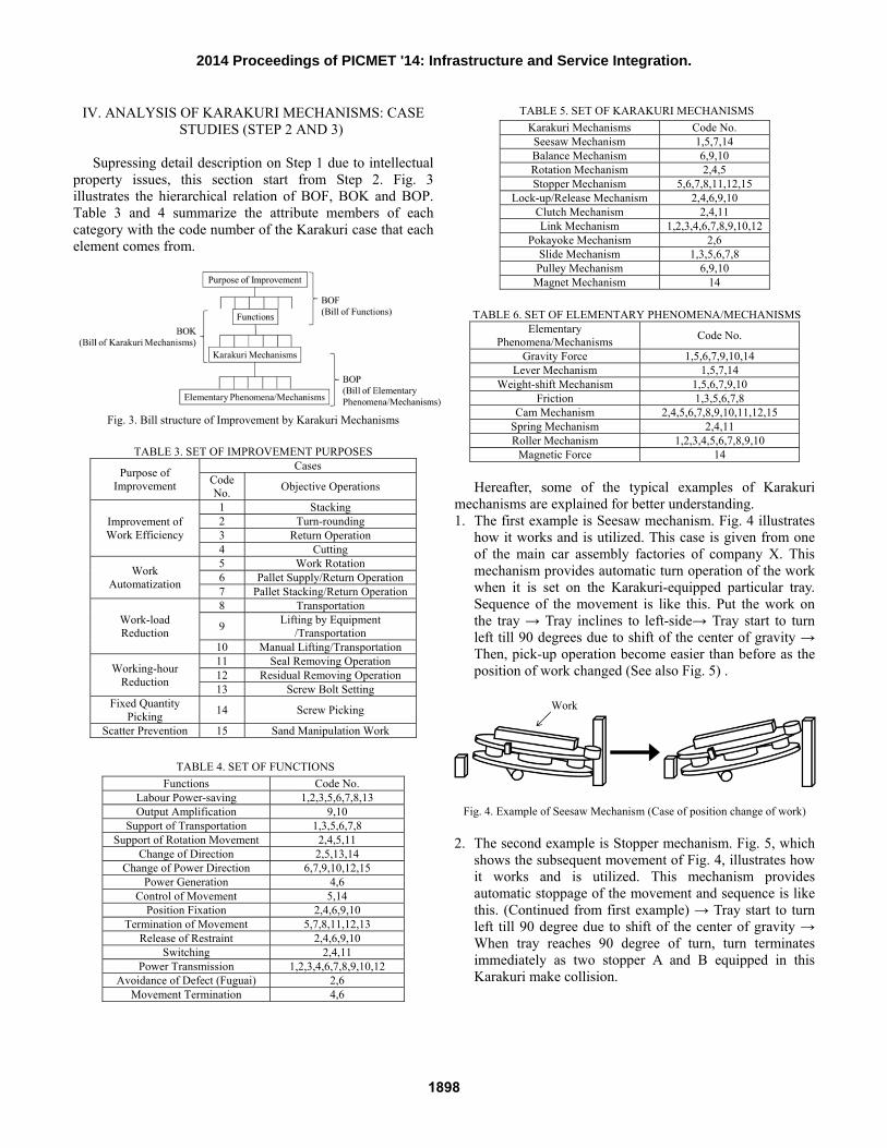
property issues, this section start from Step 2. Fig. 3 illustrates the hierarchical relation of BOF, BOK and BOP. Table 3 and 4 summarize the attribute members of each category with the code number of the Karakuri case that each element comes from.
Fig. 3. Bill structure of Improvement by Karakuri Mechanisms
TABLE 3. SET OF IMPROVEMENT PURPOSES
Purpose of Improvement
Cases Code No. Objective Operations
Improvement of Work Efficiency
1 Stacking 2 Turn-rounding 3 Return Operation 4 Cutting
Work Automatization
5 Work Rotation 6 Pallet Supply/Return Operation 7 Pallet Stacking/Return Operation
Work-load Reduction
8 Transportation
9 Lifting by Equipment /Transportation
10 Manual Lifting/Transportation
Working-hour Reduction
11 Seal Removing Operation 12 Residual Removing Operation 13 Screw Bolt Setting
Fixed Quantity Picking 14 Screw Picking
Scatter Prevention 15 Sand Manipulation Work
TABLE 4. SET OF FUNCTIONS
Functions Code No. Labour Power-saving 1,2,3,5,6,7,8,13 Output Amplification 9,10
Support of Transportation 1,3,5,6,7,8 Support of Rotation Movement 2,4,5,11
Change of Direction 2,5,13,14 Change of Power Direction 6,7,9,10,12,15
Power Generation 4,6 Control of Movement 5,14
Position Fixation 2,4,6,9,10 Termination of Movement 5,7,8,11,12,13
Release of Restraint 2,4,6,9,10 Switching 2,4,11
Power Transmission 1,2,3,4,6,7,8,9,10,12 Avoidance of Defect (Fuguai) 2,6
Movement Termination 4,6
TABLE 5. SET OF KARAKURI MECHANISMS
Karakuri Mechanisms Code No. Seesaw Mechanism 1,5,7,14 Balance Mechanism 6,9,10 Rotation Mechanism 2,4,5 Stopper Mechanism 5,6,7,8,11,12,15
Lock-up/Release Mechanism 2,4,6,9,10 Clutch Mechanism 2,4,11 Link Mechanism 1,2,3,4,6,7,8,9,10,12
Pokayoke Mechanism 2,6 Slide Mechanism 1,3,5,6,7,8 Pulley Mechanism 6,9,10
Magnet Mechanism 14
TABLE 6. SET OF ELEMENTARY PHENOMENA/MECHANISMS Elementary
Phenomena/Mechanisms Code No.
Gravity Force 1,5,6,7,9,10,14 Lever Mechanism 1,5,7,14
Weight-shift Mechanism 1,5,6,7,9,10 Friction 1,3,5,6,7,8
Cam Mechanism 2,4,5,6,7,8,9,10,11,12,15 Spring Mechanism 2,4,11 Roller Mechanism 1,2,3,4,5,6,7,8,9,10
Magnetic Force 14 Hereafter, some of the typical examples of Karakuri
mechanisms are explained for better understanding. 1. The first example is Seesaw mechanism. Fig. 4 illustrates
how it works and is utilized. This case is given from one of the main car assembly factories of company X. This mechanism provides automatic turn operation of the work when it is set on the Karakuri-equipped particular tray. Sequence of the movement is like this. Put the work on the tray → Tray inclines to left-side→ Tray start to turn left till 90 degrees due to shift of the center of gravity → Then, pick-up operation become easier than before as the position of work changed (See also Fig. 5) .
Fig. 4. Example of Seesaw Mechanism (Case of position change of work) 2. The second example is Stopper mechanism. Fig. 5, which
shows the subsequent movement of Fig. 4, illustrates how it works and is utilized. This mechanism provides automatic stoppage of the movement and sequence is like this. (Continued from first example) → Tray start to turn left till 90 degree due to shift of the center of gravity → When tray reaches 90 degree of turn, turn terminates immediately as two stopper A and B equipped in this Karakuri make collision.
Work
1898
2014 Proceedings of PICMET '14: Infrastructure and Service Integration.
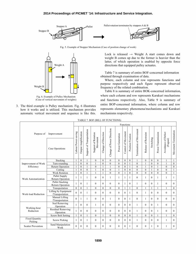
Fig. 5. Example of Stopper Mechanism (Case of position change of work)
Fig. 6. Example of Pulley Mechanism (Case of vertical movement of weights)
3. The third example is Pulley mechanism. Fig. 6 illustrates
how it works and is utilized. This mechanism provides automatic vertical movement and sequence is like this.
Lock is released → Weight A start comes down and weight B comes up due to the former is heavier than the latter, of which operation is enabled by opposite force directions that equipped pulley actuates.
Table 7 is summary of entire BOF-concerned information
obtained through examination of data. Where, each column and row represents functions and
purpose respectively and each figure represent observed frequency of the related combination.
Table 8 is summary of entire BOK-concerned information, where each column and row represents Karakuri mechanisms and functions respectively. Also, Table 9 is summary of entire BOP-concerned information, where column and row represents elementary phenomena/mechanisms and Karakuri mechanisms respectively.
TABLE 7. BOF (BILL OF FUNCTIONS)
Purpose of
Improvement
Functions
Labo
ur P
ower
-sav
ing
Out
put A
mpl
ifica
tion
Supp
ort o
f Tra
nspo
rtatio
n
Supp
ort o
f Rot
atio
n M
ovem
ent
Chan
ge o
f Dire
ctio
n
Chan
ge o
f Pow
er D
irect
ion
Pow
er G
ener
atio
n
Cont
rol o
f Mov
emen
t
Posit
ion
Fixa
tion
Term
inat
ion
of M
ovem
ent
Rele
ase
of R
estra
int
Switc
hing
Pow
er T
rans
miss
ion
Avo
idan
ce o
f Def
ect
(Fug
uai)
Mov
emen
t Ter
min
atio
n
Case Operations
Improvement of Work Efficiency
Stacking 1 0 1 0 0 0 0 0 0 1 0 0 0 1 1 Turn-rounding 1 0 0 1 0 0 0 0 1 0 1 0 0 1 0
Return Operation 1 0 1 0 1 1 0 0 1 0 1 0 1 0 0 Cutting 1 0 0 1 0 0 1 0 0 0 0 1 0 0 1
Work Automatization
Work Rotation 1 0 1 1 1 0 0 1 0 0 0 0 0 0 1 Pallet Supply
/Return Operation 1 1 1 0 0 1 1 1 1 0 1 0 1 1 1
Pallet Stacking /Return Operation 1 0 1 0 0 0 0 1 0 1 0 0 1 0 0
Work-load Reduction
Transportation 0 0 1 0 0 0 0 1 1 0 1 1 1 1 0 Lifting by Equipment
/Transportation 0 0 1 0 0 0 0 0 1 0 1 0 0 0 0
Manual Lifting /Transportation 0 1 1 0 0 1 0 0 1 0 1 0 0 0 0
Working-hour Reduction
Seal Removing Operation 1 0 0 1 0 0 0 0 0 1 0 0 1 0 0
Residual Removing Operation 1 0 0 0 0 0 0 0 0 1 0 0 1 0 0
Screw Bolt Setting 1 0 1 0 1 0 0 0 0 1 0 0 1 1 0 Fixed Quantity
Picking Screw Picking 1 0 1 0 0 0 0 0 0 1 0 0 0 1 0
Scatter Prevention Sand Manipulation Work 0 0 0 0 0 0 0 0 1 0 0 1 0 1 0
1899
2014 Proceedings of PICMET '14: Infrastructure and Service Integration.
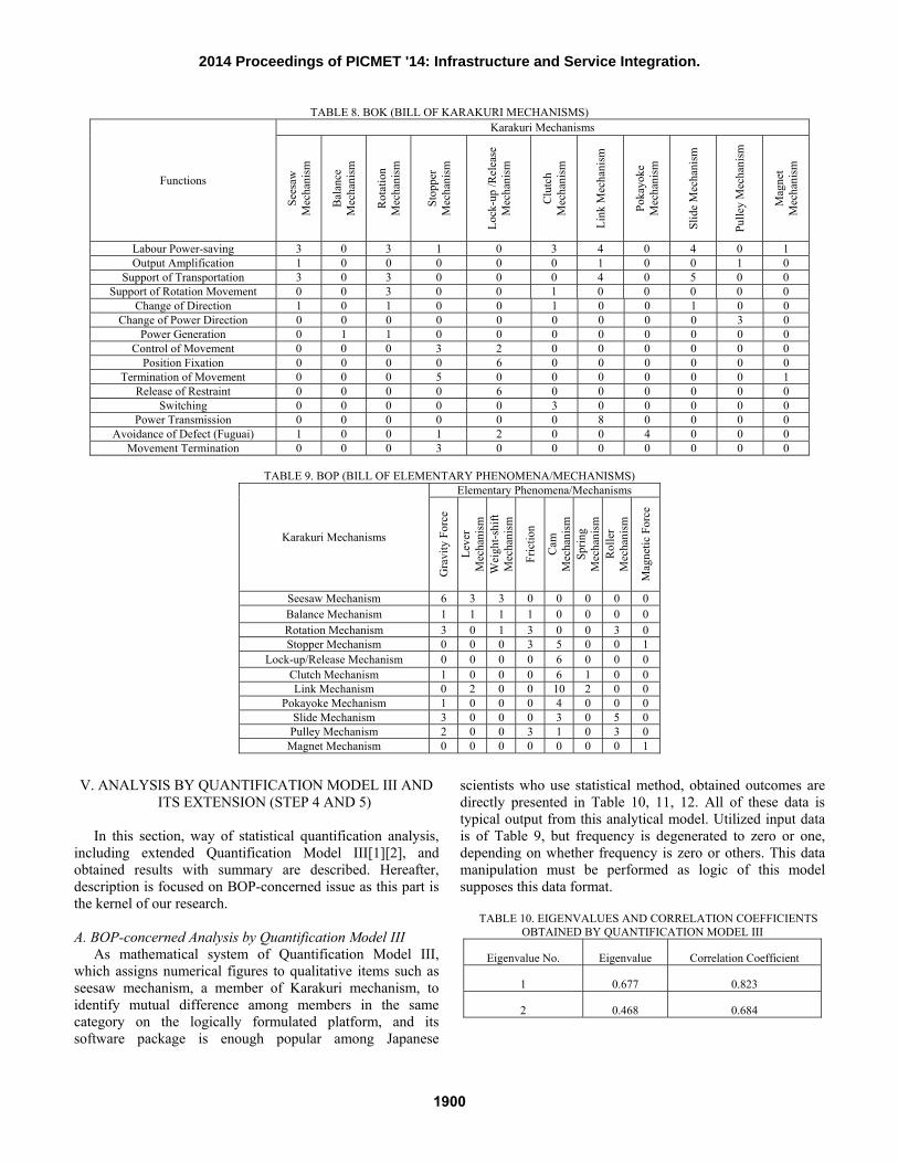
TABLE 8. BOK (BILL OF KARAKURI MECHANISMS)
Functions
Karakuri Mechanisms
Sees
aw
Mec
hani
sm
Bala
nce
Mec
hani
sm
Rota
tion
Mec
hani
sm
Stop
per
Mec
hani
sm
Lock
-up
/Rel
ease
M
echa
nism
Clut
ch
Mec
hani
sm
Link
Mec
hani
sm
Poka
yoke
M
echa
nism
Slid
e M
echa
nism
Pulle
y M
echa
nism
Mag
net
Mec
hani
sm
Labour Power-saving 3 0 3 1 0 3 4 0 4 0 1 Output Amplification 1 0 0 0 0 0 1 0 0 1 0
Support of Transportation 3 0 3 0 0 0 4 0 5 0 0 Support of Rotation Movement 0 0 3 0 0 1 0 0 0 0 0
Change of Direction 1 0 1 0 0 1 0 0 1 0 0 Change of Power Direction 0 0 0 0 0 0 0 0 0 3 0
Power Generation 0 1 1 0 0 0 0 0 0 0 0 Control of Movement 0 0 0 3 2 0 0 0 0 0 0
Position Fixation 0 0 0 0 6 0 0 0 0 0 0 Termination of Movement 0 0 0 5 0 0 0 0 0 0 1
Release of Restraint 0 0 0 0 6 0 0 0 0 0 0 Switching 0 0 0 0 0 3 0 0 0 0 0
Power Transmission 0 0 0 0 0 0 8 0 0 0 0 Avoidance of Defect (Fuguai) 1 0 0 1 2 0 0 4 0 0 0
Movement Termination 0 0 0 3 0 0 0 0 0 0 0
TABLE 9. BOP (BILL OF ELEMENTARY PHENOMENA/MECHANISMS)
Karakuri Mechanisms
Elementary Phenomena/Mechanisms
Gra
vity
For
ce
Leve
r M
echa
nism
W
eigh
t-shi
ft M
echa
nism
Fric
tion
Cam
M
echa
nism
Sp
ring
Mec
hani
sm
Rolle
r M
echa
nism
Mag
netic
For
ce
Seesaw Mechanism 6 3 3 0 0 0 0 0 Balance Mechanism 1 1 1 1 0 0 0 0 Rotation Mechanism 3 0 1 3 0 0 3 0 Stopper Mechanism 0 0 0 3 5 0 0 1
Lock-up/Release Mechanism 0 0 0 0 6 0 0 0 Clutch Mechanism 1 0 0 0 6 1 0 0 Link Mechanism 0 2 0 0 10 2 0 0
Pokayoke Mechanism 1 0 0 0 4 0 0 0 Slide Mechanism 3 0 0 0 3 0 5 0
Pulley Mechanism 2 0 0 3 1 0 3 0 Magnet Mechanism 0 0 0 0 0 0 0 1
V. ANALYSIS BY QUANTIFICATION MODEL III AND
ITS EXTENSION (STEP 4 AND 5)
In this section, way of statistical quantification analysis, including extended Quantification Model III[1][2], and obtained results with summary are described. Hereafter, description is focused on BOP-concerned issue as this part is the kernel of our research. A. BOP-concerned Analysis by Quantification Model III
As mathematical system of Quantification Model III, which assigns numerical figures to qualitative items such as seesaw mechanism, a member of Karakuri mechanism, to identify mutual difference among members in the same category on the logically formulated platform, and its software package is enough popular among Japanese
scientists who use statistical method, obtained outcomes are directly presented in Table 10, 11, 12. All of these data is typical output from this analytical model. Utilized input data is of Table 9, but frequency is degenerated to zero or one, depending on whether frequency is zero or others. This data manipulation must be performed as logic of this model supposes this data format.
TABLE 10. EIGENVALUES AND CORRELATION COEFFICIENTS OBTAINED BY QUANTIFICATION MODEL III
Eigenvalue No. Eigenvalue Correlation Coefficient
1 0.677 0.823
2 0.468 0.684
1900
2014 Proceedings of PICMET '14: Infrastructure and Service Integration.
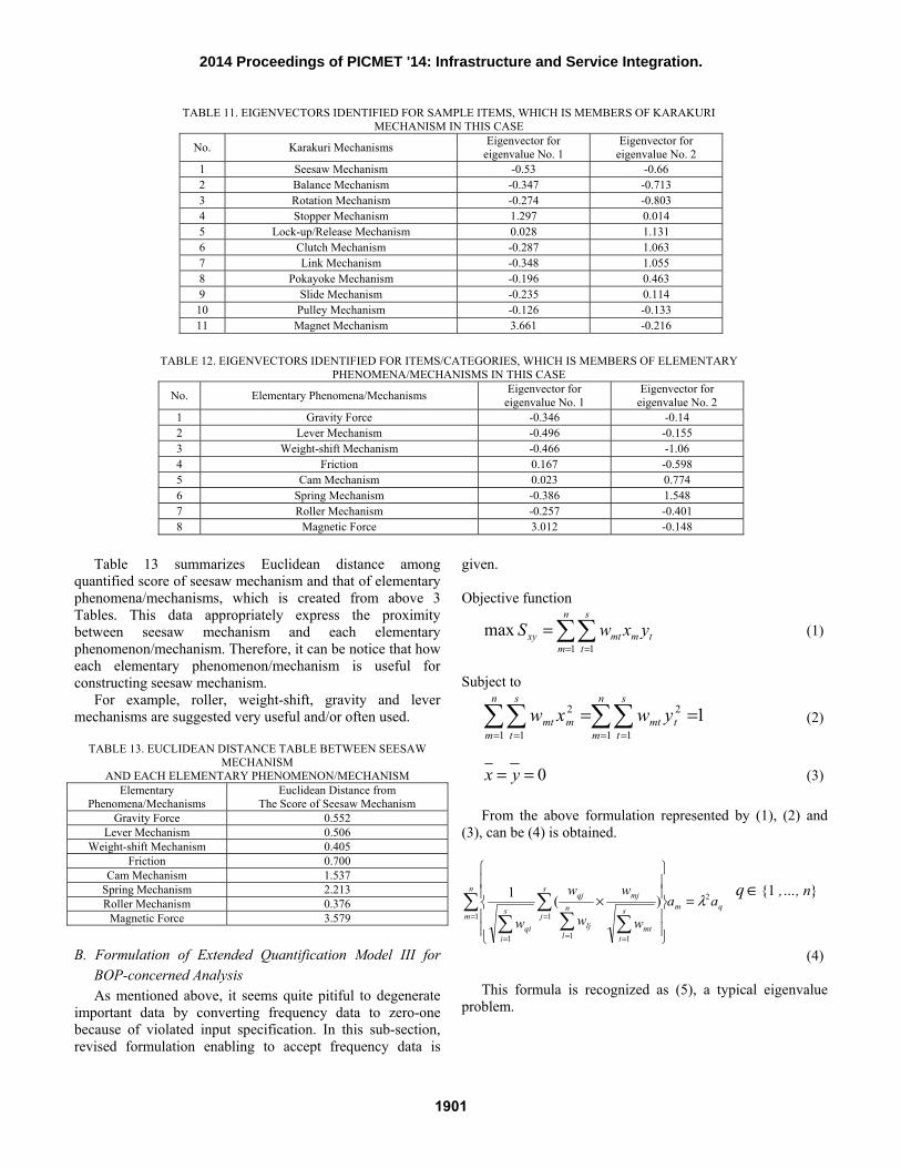
TABLE 11. EIGENVECTORS IDENTIFIED FOR SAMPLE ITEMS, WHICH IS MEMBERS OF KARAKURI MECHANISM IN THIS CASE
No. Karakuri Mechanisms Eigenvector for eigenvalue No. 1
Eigenvector for eigenvalue No. 2
1 Seesaw Mechanism -0.53 -0.66 2 Balance Mechanism -0.347 -0.713 3 Rotation Mechanism -0.274 -0.803 4 Stopper Mechanism 1.297 0.014 5 Lock-up/Release Mechanism 0.028 1.131 6 Clutch Mechanism -0.287 1.063 7 Link Mechanism -0.348 1.055 8 Pokayoke Mechanism -0.196 0.463 9 Slide Mechanism -0.235 0.114 10 Pulley Mechanism -0.126 -0.133 11 Magnet Mechanism 3.661 -0.216
TABLE 12. EIGENVECTORS IDENTIFIED FOR ITEMS/CATEGORIES, WHICH IS MEMBERS OF ELEMENTARY
PHENOMENA/MECHANISMS IN THIS CASE
No. Elementary Phenomena/Mechanisms Eigenvector for eigenvalue No. 1
Eigenvector for eigenvalue No. 2
1 Gravity Force -0.346 -0.14 2 Lever Mechanism -0.496 -0.155 3 Weight-shift Mechanism -0.466 -1.06 4 Friction 0.167 -0.598 5 Cam Mechanism 0.023 0.774 6 Spring Mechanism -0.386 1.548 7 Roller Mechanism -0.257 -0.401 8 Magnetic Force 3.012 -0.148
Table 13 summarizes Euclidean distance among
quantified score of seesaw mechanism and that of elementary phenomena/mechanisms, which is created from above 3 Tables. This data appropriately express the proximity between seesaw mechanism and each elementary phenomenon/mechanism. Therefore, it can be notice that how each elementary phenomenon/mechanism is useful for constructing seesaw mechanism.
For example, roller, weight-shift, gravity and lever mechanisms are suggested very useful and/or often used.
TABLE 13. EUCLIDEAN DISTANCE TABLE BETWEEN SEESAW
MECHANISM AND EACH ELEMENTARY PHENOMENON/MECHANISM
Elementary Phenomena/Mechanisms
Euclidean Distance from The Score of Seesaw Mechanism
Gravity Force 0.552 Lever Mechanism 0.506
Weight-shift Mechanism 0.405 Friction 0.700
Cam Mechanism 1.537 Spring Mechanism 2.213 Roller Mechanism 0.376
Magnetic Force 3.579
B. Formulation of Extended Quantification Model III for BOP-concerned Analysis As mentioned above, it seems quite pitiful to degenerate
important data by converting frequency data to zero-one because of violated input specification. In this sub-section, revised formulation enabling to accept frequency data is
given. Objective function
= =
=n
m
s
ttmmtxy yxwS
1 1max (1)
Subject to
= == =
==n
m
s
ttmt
n
m
s
tmmt ywxw
1 1
2
1 1
2 1 (2)
0== yx (3)
From the above formulation represented by (1), (2) and (3), can be (4) is obtained.
qm
n
m
s
js
tmt
mjn
llj
qj
s
iqi
aaw
w
w
w
w
2
1 1
111
)(1 λ=
× = =
===
∈q {1 ,…, n}
(4)
This formula is recognized as (5), a typical eigenvalue problem.
1901
2014 Proceedings of PICMET '14: Infrastructure and Service Integration.
=
n
q
n
m
a
a
aa
a
a
aa
A
2
1
2
2
1
λ (5)
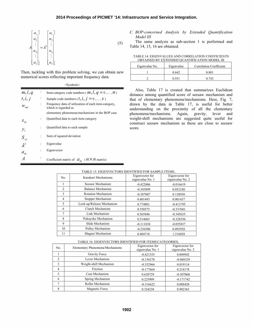
Then, tackling with this problem solving, we can obtain new numerical scores reflecting important frequency data.
<Symbols>
qlm ,, : Item-category code numbers ( =qlm ,, 0 ,… , n )
jit ,, : Sample code numbers ( =jit ,, 0 ,… , s )
mtw : Frequency data of utilization of each item-category, which is regarded as elementary phenomena/mechanisms in the BOP case
mx
: Quantified data to each item-category
ty
: Quantified data to each sample
xyS : Sum of squared deviation
2λ : Eigenvalue
ma : Eigenvector
A : Coefficient matrix of ma ( nn × matrix)
C. BOP-concerned Analysis by Extended Quantification Model III The same analysis as sub-section 1 is performed and
Table 14, 15, 16 are obtained.
TABLE 14. EIGENVALUES AND CORRELATION COEFFICIENTS OBTAINED BY EXTENDED QUANTIFICATION MODEL III
Eigenvalue No. Eigenvalue Correlation Coefficient
1 0.642 0.801
2 0.551 0.742
Also, Table 17 is created that summarizes Euclidean
distance among quantified score of seesaw mechanism and that of elementary phenomena/mechanisms. Here, Fig. 7, drawn by the data in Table 17, is useful for better understanding on the proximity of all the elementary phenomena/mechanisms. Again, gravity, lever and weight-shift mechanisms are suggested quite useful for construct seesaw mechanism as these are close to seesaw score.
TABLE 15. EIGENVECTORS IDENTIFIED FOR SAMPLE ITEMS,
No. Karakuri Mechanisms Eigenvector for eigenvalue No. 1
Eigenvector for eigenvalue No. 2
1 Seesaw Mechanism -0.422006 -0.016619 2 Balance Mechanism -0.345899 0.052188 3 Rotation Mechanism -0.387007 0.128930 4 Stopper Mechanism 0.401493 0.001437 5 Lock-up/Release Mechanism 0.774801 -0.413795 6 Clutch Mechanism 0.550575 -0.337601 7 Link Mechanism 0.565846 -0.345635 8 Pokayoke Mechanism 0.514603 -0.328356 9 Slide Mechanism -0.111838 -0.055037 10 Pulley Mechanism -0.236500 0.092928 11 Magnet Mechanism 0.404718 1.216028
TABLE 16. EIGENVECTORS IDENTIFIED FOR ITEMS/CATEGORIES,
No. Elementary Phenomena/Mechanisms Eigenvector for eigenvalue No. 1
Eigenvector for eigenvalue No. 2
1 Gravity Force -0.421555 0.009942 2 Lever Mechanism -0.156278 -0.088329 3 Weight-shift Mechanism -0.352966 0.019114 4 Friction -0.177664 0.214178 5 Cam Mechanism 0.620729 -0.307060 6 Spring Mechanism 0.225909 -0.171742 7 Roller Mechanism -0.316622 0.088420 8 Magnetic Force 0.324238 0.902365
1902
2014 Proceedings of PICMET '14: Infrastructure and Service Integration.
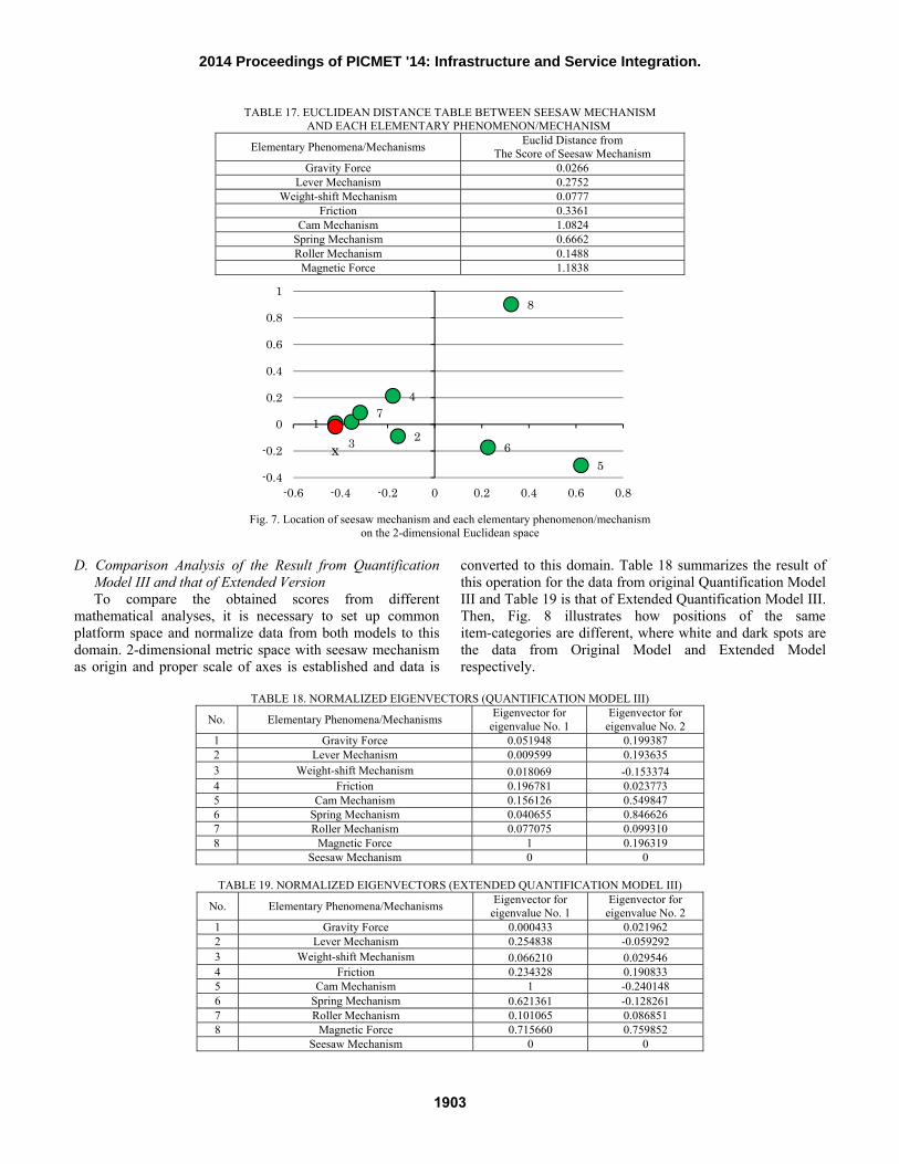
TABLE 17. EUCLIDEAN DISTANCE TABLE BETWEEN SEESAW MECHANISM AND EACH ELEMENTARY PHENOMENON/MECHANISM
Elementary Phenomena/Mechanisms Euclid Distance from The Score of Seesaw Mechanism
Gravity Force 0.0266 Lever Mechanism 0.2752
Weight-shift Mechanism 0.0777 Friction 0.3361
Cam Mechanism 1.0824 Spring Mechanism 0.6662 Roller Mechanism 0.1488
Magnetic Force 1.1838
Fig. 7. Location of seesaw mechanism and each elementary phenomenon/mechanism
on the 2-dimensional Euclidean space D. Comparison Analysis of the Result from Quantification
Model III and that of Extended Version To compare the obtained scores from different
mathematical analyses, it is necessary to set up common platform space and normalize data from both models to this domain. 2-dimensional metric space with seesaw mechanism as origin and proper scale of axes is established and data is
converted to this domain. Table 18 summarizes the result of this operation for the data from original Quantification Model III and Table 19 is that of Extended Quantification Model III. Then, Fig. 8 illustrates how positions of the same item-categories are different, where white and dark spots are the data from Original Model and Extended Model respectively.
TABLE 18. NORMALIZED EIGENVECTORS (QUANTIFICATION MODEL III)
No. Elementary Phenomena/Mechanisms Eigenvector for eigenvalue No. 1
Eigenvector for eigenvalue No. 2
1 Gravity Force 0.051948 0.199387 2 Lever Mechanism 0.009599 0.193635 3 Weight-shift Mechanism 0.018069 -0.153374 4 Friction 0.196781 0.023773 5 Cam Mechanism 0.156126 0.549847 6 Spring Mechanism 0.040655 0.846626 7 Roller Mechanism 0.077075 0.099310 8 Magnetic Force 1 0.196319
Seesaw Mechanism 0 0
TABLE 19. NORMALIZED EIGENVECTORS (EXTENDED QUANTIFICATION MODEL III)
No. Elementary Phenomena/Mechanisms Eigenvector for eigenvalue No. 1
Eigenvector for eigenvalue No. 2
1 Gravity Force 0.000433 0.021962 2 Lever Mechanism 0.254838 -0.059292 3 Weight-shift Mechanism 0.066210 0.029546 4 Friction 0.234328 0.190833 5 Cam Mechanism 1 -0.240148 6 Spring Mechanism 0.621361 -0.128261 7 Roller Mechanism 0.101065 0.086851 8 Magnetic Force 0.715660 0.759852
Seesaw Mechanism 0 0
123
4
56
7
8
x-0.4
-0.2
0
0.2
0.4
0.6
0.8
1
-0.6 -0.4 -0.2 0 0.2 0.4 0.6 0.8
1903
2014 Proceedings of PICMET '14: Infrastructure and Service Integration.
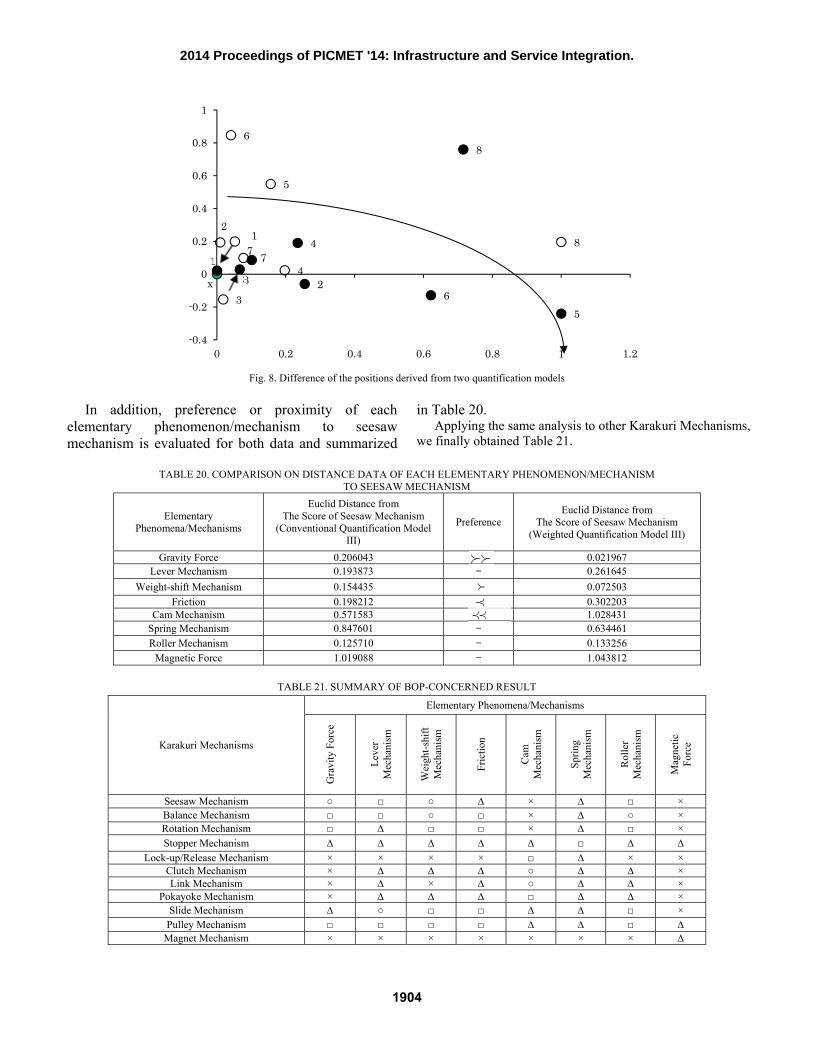
Fig. 8. Difference of the positions derived from two quantification models
In addition, preference or proximity of each
elementary phenomenon/mechanism to seesaw mechanism is evaluated for both data and summarized
in Table 20. Applying the same analysis to other Karakuri Mechanisms,
we finally obtained Table 21.
TABLE 20. COMPARISON ON DISTANCE DATA OF EACH ELEMENTARY PHENOMENON/MECHANISM TO SEESAW MECHANISM
Elementary Phenomena/Mechanisms
Euclid Distance from The Score of Seesaw Mechanism
(Conventional Quantification Model III)
Preference Euclid Distance from
The Score of Seesaw Mechanism (Weighted Quantification Model III)
Gravity Force 0.206043 0.021967 Lever Mechanism 0.193873 - 0.261645
Weight-shift Mechanism 0.154435
0.072503 Friction 0.198212 0.302203
Cam Mechanism 0.571583 1.028431 Spring Mechanism 0.847601 - 0.634461 Roller Mechanism 0.125710 - 0.133256
Magnetic Force 1.019088 - 1.043812
TABLE 21. SUMMARY OF BOP-CONCERNED RESULT
Karakuri Mechanisms
Elementary Phenomena/Mechanisms
Gra
vity
For
ce
Leve
r M
echa
nism
Wei
ght-s
hift
Mec
hani
sm
Fric
tion
Cam
M
echa
nism
Sprin
g M
echa
nism
Rolle
r M
echa
nism
Mag
netic
Fo
rce
Seesaw Mechanism ○ □ ○ ∆ × ∆ □ ×
Balance Mechanism □ □ ○ □ × ∆ ○ ×
Rotation Mechanism □ ∆ □ □ × ∆ □ ×
Stopper Mechanism ∆ ∆ ∆ ∆ ∆ □ ∆ ∆
Lock-up/Release Mechanism × × × × □ ∆ × × Clutch Mechanism × ∆ ∆ ∆ ○ ∆ ∆ × Link Mechanism × ∆ × ∆ ○ ∆ ∆ ×
Pokayoke Mechanism × ∆ ∆ ∆ □ ∆ ∆ ×
Slide Mechanism ∆ ○ □ □ ∆ ∆ □ ×
Pulley Mechanism □ □ □ □ ∆ ∆ □ ∆
Magnet Mechanism × × × × × × × ∆
12
3
4
5
6
78
x
1
23
4
56
7
8
-0.4
-0.2
0
0.2
0.4
0.6
0.8
1
0 0.2 0.4 0.6 0.8 1 1.2
1904
2014 Proceedings of PICMET '14: Infrastructure and Service Integration.
Where, the symbols in table 21 are defined as follows. ○: 0≦x≦0.07 □: 0.07<x≦0.31 ∆: 0.31<x≦0.69 ×: 0.69<x≦1 x: Normalized value of quantified scores of each model
This sort of knowledge can be very useful for managing Karakuri development and improvement projects effectively. Some consideration on this matter is given in the next section.
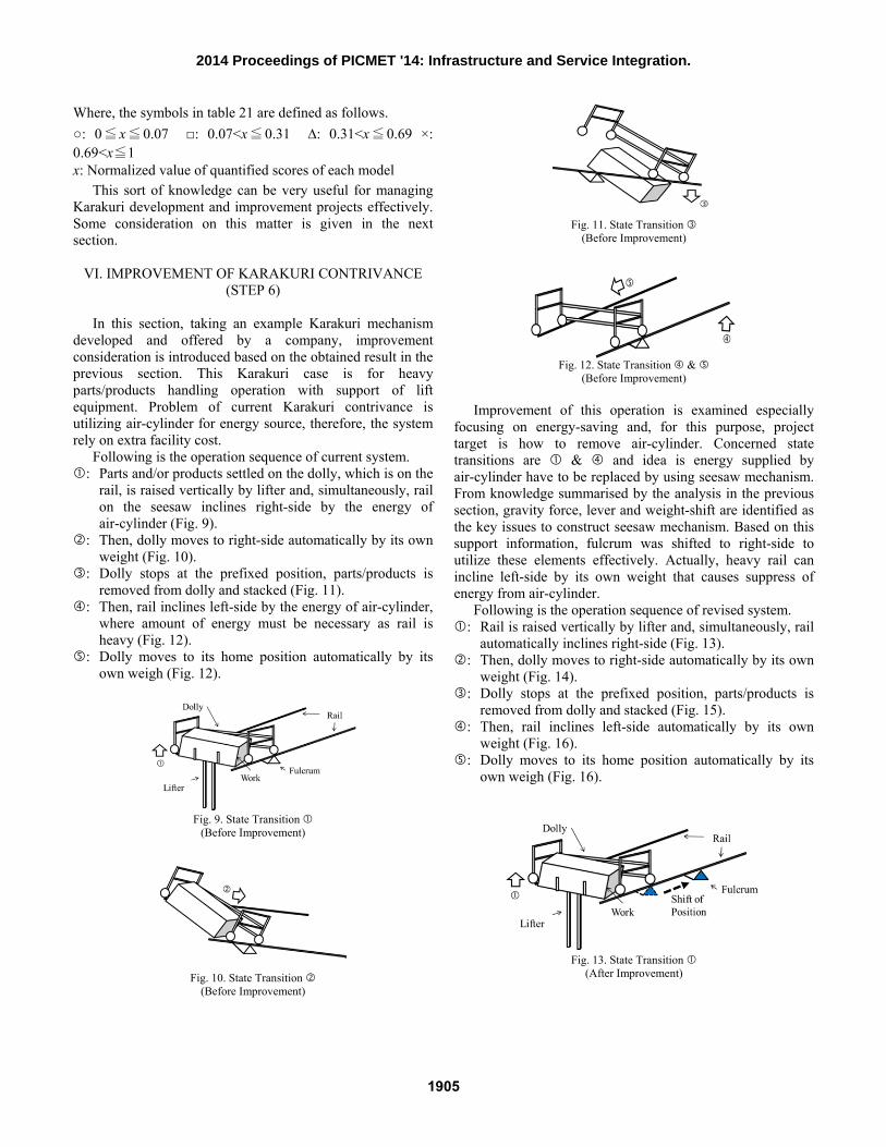
VI. IMPROVEMENT OF KARAKURI CONTRIVANCE (STEP 6)
In this section, taking an example Karakuri mechanism
developed and offered by a company, improvement consideration is introduced based on the obtained result in the previous section. This Karakuri case is for heavy parts/products handling operation with support of lift equipment. Problem of current Karakuri contrivance is utilizing air-cylinder for energy source, therefore, the system rely on extra facility cost.
Following is the operation sequence of current system. : Parts and/or products settled on the dolly, which is on the
rail, is raised vertically by lifter and, simultaneously, rail on the seesaw inclines right-side by the energy of air-cylinder (Fig. 9).
: Then, dolly moves to right-side automatically by its own weight (Fig. 10).
: Dolly stops at the prefixed position, parts/products is removed from dolly and stacked (Fig. 11).
: Then, rail inclines left-side by the energy of air-cylinder, where amount of energy must be necessary as rail is heavy (Fig. 12).
: Dolly moves to its home position automatically by its own weigh (Fig. 12).
Fig. 9. State Transition
(Before Improvement)
Fig. 10. State Transition (Before Improvement)
Fig. 11. State Transition
(Before Improvement)
Fig. 12. State Transition &
(Before Improvement)
Improvement of this operation is examined especially focusing on energy-saving and, for this purpose, project target is how to remove air-cylinder. Concerned state transitions are & and idea is energy supplied by air-cylinder have to be replaced by using seesaw mechanism. From knowledge summarised by the analysis in the previous section, gravity force, lever and weight-shift are identified as the key issues to construct seesaw mechanism. Based on this support information, fulcrum was shifted to right-side to utilize these elements effectively. Actually, heavy rail can incline left-side by its own weight that causes suppress of energy from air-cylinder.
Following is the operation sequence of revised system. : Rail is raised vertically by lifter and, simultaneously, rail
automatically inclines right-side (Fig. 13). : Then, dolly moves to right-side automatically by its own
weight (Fig. 14). : Dolly stops at the prefixed position, parts/products is
removed from dolly and stacked (Fig. 15). : Then, rail inclines left-side automatically by its own
weight (Fig. 16). : Dolly moves to its home position automatically by its
own weigh (Fig. 16).
Fig. 13. State Transition
(After Improvement)
1905
2014 Proceedings of PICMET '14: Infrastructure and Service Integration.
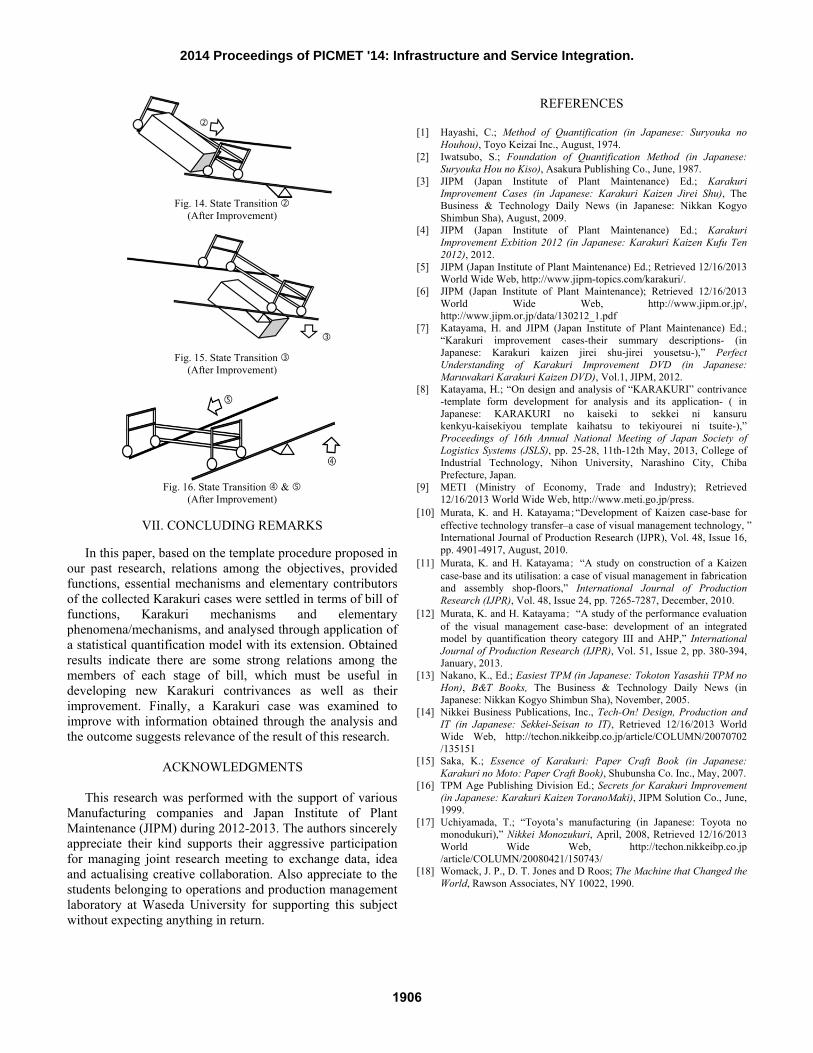
Fig. 14. State Transition
(After Improvement)
Fig. 15. State Transition
(After Improvement)
Fig. 16. State Transition &
(After Improvement)
VII. CONCLUDING REMARKS
In this paper, based on the template procedure proposed in our past research, relations among the objectives, provided functions, essential mechanisms and elementary contributors of the collected Karakuri cases were settled in terms of bill of functions, Karakuri mechanisms and elementary phenomena/mechanisms, and analysed through application of a statistical quantification model with its extension. Obtained results indicate there are some strong relations among the members of each stage of bill, which must be useful in developing new Karakuri contrivances as well as their improvement. Finally, a Karakuri case was examined to improve with information obtained through the analysis and the outcome suggests relevance of the result of this research.
ACKNOWLEDGMENTS
This research was performed with the support of various Manufacturing companies and Japan Institute of Plant Maintenance (JIPM) during 2012-2013. The authors sincerely appreciate their kind supports their aggressive participation for managing joint research meeting to exchange data, idea and actualising creative collaboration. Also appreciate to the students belonging to operations and production management laboratory at Waseda University for supporting this subject without expecting anything in return.
REFERENCES [1] Hayashi, C.; Method of Quantification (in Japanese: Suryouka no
Houhou), Toyo Keizai Inc., August, 1974. [2] Iwatsubo, S.; Foundation of Quantification Method (in Japanese:
Suryouka Hou no Kiso), Asakura Publishing Co., June, 1987. [3] JIPM (Japan Institute of Plant Maintenance) Ed.; Karakuri
Improvement Cases (in Japanese: Karakuri Kaizen Jirei Shu), The Business & Technology Daily News (in Japanese: Nikkan Kogyo Shimbun Sha), August, 2009.
[4] JIPM (Japan Institute of Plant Maintenance) Ed.; Karakuri Improvement Exbition 2012 (in Japanese: Karakuri Kaizen Kufu Ten 2012), 2012.
[5] JIPM (Japan Institute of Plant Maintenance) Ed.; Retrieved 12/16/2013 World Wide Web, http://www.jipm-topics.com/karakuri/.
[6] JIPM (Japan Institute of Plant Maintenance); Retrieved 12/16/2013 World Wide Web, http://www.jipm.or.jp/, http://www.jipm.or.jp/data/130212_1.pdf
[7] Katayama, H. and JIPM (Japan Institute of Plant Maintenance) Ed.; “Karakuri improvement cases-their summary descriptions- (in Japanese: Karakuri kaizen jirei shu-jirei yousetsu-),” Perfect Understanding of Karakuri Improvement DVD (in Japanese: Maruwakari Karakuri Kaizen DVD), Vol.1, JIPM, 2012.
[8] Katayama, H.; “On design and analysis of “KARAKURI” contrivance -template form development for analysis and its application- ( in Japanese: KARAKURI no kaiseki to sekkei ni kansuru kenkyu-kaisekiyou template kaihatsu to tekiyourei ni tsuite-),” Proceedings of 16th Annual National Meeting of Japan Society of Logistics Systems (JSLS), pp. 25-28, 11th-12th May, 2013, College of Industrial Technology, Nihon University, Narashino City, Chiba Prefecture, Japan.
[9] METI (Ministry of Economy, Trade and Industry); Retrieved 12/16/2013 World Wide Web, http://www.meti.go.jp/press.
[10] Murata, K. and H. Katayama;“Development of Kaizen case-base for effective technology transfer–a case of visual management technology, ” International Journal of Production Research (IJPR), Vol. 48, Issue 16, pp. 4901-4917, August, 2010.
[11] Murata, K. and H. Katayama; “A study on construction of a Kaizen case-base and its utilisation: a case of visual management in fabrication and assembly shop-floors,” International Journal of Production Research (IJPR), Vol. 48, Issue 24, pp. 7265-7287, December, 2010.
[12] Murata, K. and H. Katayama; “A study of the performance evaluation of the visual management case-base: development of an integrated model by quantification theory category III and AHP,” International Journal of Production Research (IJPR), Vol. 51, Issue 2, pp. 380-394, January, 2013.
[13] Nakano, K., Ed.; Easiest TPM (in Japanese: Tokoton Yasashii TPM no Hon), B&T Books, The Business & Technology Daily News (in Japanese: Nikkan Kogyo Shimbun Sha), November, 2005.
[14] Nikkei Business Publications, Inc., Tech-On! Design, Production and IT (in Japanese: Sekkei-Seisan to IT), Retrieved 12/16/2013 World Wide Web, http://techon.nikkeibp.co.jp/article/COLUMN/20070702 /135151
[15] Saka, K.; Essence of Karakuri: Paper Craft Book (in Japanese: Karakuri no Moto: Paper Craft Book), Shubunsha Co. Inc., May, 2007.
[16] TPM Age Publishing Division Ed.; Secrets for Karakuri Improvement (in Japanese: Karakuri Kaizen ToranoMaki), JIPM Solution Co., June, 1999.
[17] Uchiyamada, T.; “Toyota’s manufacturing (in Japanese: Toyota no monodukuri),” Nikkei Monozukuri, April, 2008, Retrieved 12/16/2013 World Wide Web, http://techon.nikkeibp.co.jp /article/COLUMN/20080421/150743/
[18] Womack, J. P., D. T. Jones and D Roos; The Machine that Changed the World, Rawson Associates, NY 10022, 1990.
1906
2014 Proceedings of PICMET '14: Infrastructure and Service Integration.