Analyses of the loadbearing behaviour of ... -...
7
167 © Ernst & Sohn Verlag für Architektur und technische Wissenschaften GmbH & Co. KG, Berlin · Steel Construction 8 (2015), No. 3 Articles DOI: 10.1002/stco.201510024 The development of the “CoSFB-Betondübel” is presented in this paper. The “CoSFB-Be- tondübel” is a deep-embedded concrete dowel connecting in situ concrete with a steel section to assure composite action and thus allow for composite beam design. The load- bearing behaviour and parameters influencing this behaviour were determined through experimental tests. Special focus was given to the influence of the ratio of the resistance of the concrete dowel to the concrete compression class. The evaluation of the results concluded in a National Technical Approval [1]. Further investigations were performed via FE analysis in ABAQUS. Further, 3D models with non-linear material and geometry were prepared and validation undertaken. In addition, a real application example of CoSFB is shown. 1 Deep-embedded concrete dowels – “CoSFB-Betondübel” Concrete dowels consist of circular openings in the web of a hot-rolled steel section, reinforcing bars passing through the openings and a concrete infill (Fig. 1), see [2]. Owing to the connection of the in situ concrete with the web of the steel section, the concrete topping above the upper flange can be re- duced to a minimum, which also al- lows for optimum structural use of the depth of the construction. In the ab- sence of design rules for this kind of application for concrete dowels, beam tests and push-out tests had to be per- formed to allow for safe and opti- mized use of this technology (see sec- tion 3). Compared with other types of concrete dowel [3], deep-embedded dowels are defined by the absence of possible concrete failure towards a free edge of the cross-section. The “CoSFB-Betondübel” is a concrete dowel placed between the flanges of a hot-rolled section [1]. As the concrete here is restrained by the upper and lower flanges and the web of the steel section, failure of the concrete as a result of expansion towards a free edge cannot occur [4]. 2 Slim-floor construction Slim-floor construction is character- ized by the integration of the steel beam into the slab, which results in a very slim structure. Owing to the ab- sence of downstand beams, the instal- lation of building services (e.g. for cooling, heating) is not affected by the loadbearing members. This leads to major simplifications in the design and erection phases of the structure (Fig. 2). Further, the integration of a slim- floor beam (SFB) into the slab results in a significant increase in the fire re- sistance of the beam. The combina- tion of SFB with partially prefabri- cated concrete slabs or deep compos- ite decking allows for large beam spacings and leads to an optimized steel consumption (beam weight per square metre of slab). Restricting the construction depth consequently leads to a limited inertia and stiffness of the slim-floor beam. Therefore, Matthias Braun* Renata Obiala Christoph Odenbreit Analyses of the loadbearing behaviour of deep-embedded concrete dowels, CoSFB Selected and reviewed by the Scientific Committee of the 13th Nordic Steel Construction Conference, 23 to 25 September 2015, Tampere, Finland * Corresponding author: [email protected] Fig. 1. CoSFB – composite slim-floor beam [2] Fig. 2. Typical slim-floor construction
Transcript of Analyses of the loadbearing behaviour of ... -...
167© Ernst & Sohn Verlag für Architektur und technische Wissenschaften GmbH & Co. KG, Berlin · Steel Construction 8 (2015), No. 3
Articles
DOI: 10.1002/stco.201510024
The development of the “CoSFB-Betondübel” is presented in this paper. The “CoSFB-Be-tondübel” is a deep-embedded concrete dowel connecting in situ concrete with a steel section to assure composite action and thus allow for composite beam design. The load-bearing behaviour and parameters influencing this behaviour were determined through experimental tests. Special focus was given to the influence of the ratio of the resistance of the concrete dowel to the concrete compression class. The evaluation of the results concluded in a National Technical Approval [1]. Further investigations were performed via FE analysis in ABAQUS. Further, 3D models with non-linear material and geometry were prepared and validation undertaken. In addition, a real application example of CoSFB is shown.
1 Deep-embedded concrete dowels – “CoSFB-Betondübel”
Concrete dowels consist of circular openings in the web of a hot-rolled steel section, reinforcing bars passing through the openings and a concrete infill (Fig. 1), see [2].
Owing to the connection of the in situ concrete with the web of the steel section, the concrete topping above the upper flange can be re-duced to a minimum, which also al-lows for optimum structural use of the depth of the construction. In the ab-sence of design rules for this kind of application for concrete dowels, beam tests and push-out tests had to be per-formed to allow for safe and opti-mized use of this technology (see sec-tion 3). Compared with other types of concrete dowel [3], deep-embedded dowels are defined by the absence of possible concrete failure towards a free edge of the cross-section. The “CoSFB-Betondübel” is a concrete
dowel placed between the flanges of a hot-rolled section [1]. As the concrete here is restrained by the upper and lower flanges and the web of the steel section, failure of the concrete as a result of expansion towards a free edge cannot occur [4].
2 Slim-floor construction
Slim-floor construction is character-ized by the integration of the steel beam into the slab, which results in a very slim structure. Owing to the ab-sence of downstand beams, the instal-lation of building services (e.g. for cooling, heating) is not affected by the loadbearing members. This leads to major simplifications in the design and erection phases of the structure (Fig. 2).
Further, the integration of a slim-floor beam (SFB) into the slab results in a significant increase in the fire re-sistance of the beam. The combina-tion of SFB with partially prefabri-cated concrete slabs or deep compos-ite decking allows for large beam spacings and leads to an optimized steel consumption (beam weight per square metre of slab). Restricting the construction depth consequently leads to a limited inertia and stiffness of the slim-floor beam. Therefore,
Matthias Braun*Renata ObialaChristoph Odenbreit
Analyses of the loadbearing behaviour of deep-embedded concrete dowels, CoSFB
Selected and reviewed by the Scientific Committee of the 13th Nordic Steel Construction Conference, 23 to 25 September 2015, Tampere, Finland * Corresponding author:
[email protected] Fig. 1. CoSFB – composite slim-floor beam [2]
Fig. 2. Typical slim-floor construction
M. Braun/R. Obiala/Chr. Odenbreit · Analyses of the loadbearing behaviour of deep-embedded concrete dowels, CoSFB
168 Steel Construction 8 (2015), No. 3
culated. The whole width of the con-crete slab of the specimen was acti-vated. Further, full composite action between the steel section and the con-crete chord could be proved. For fur-ther details see [5].
3.1 Push-out tests
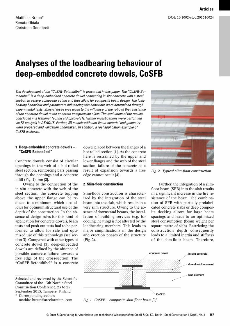
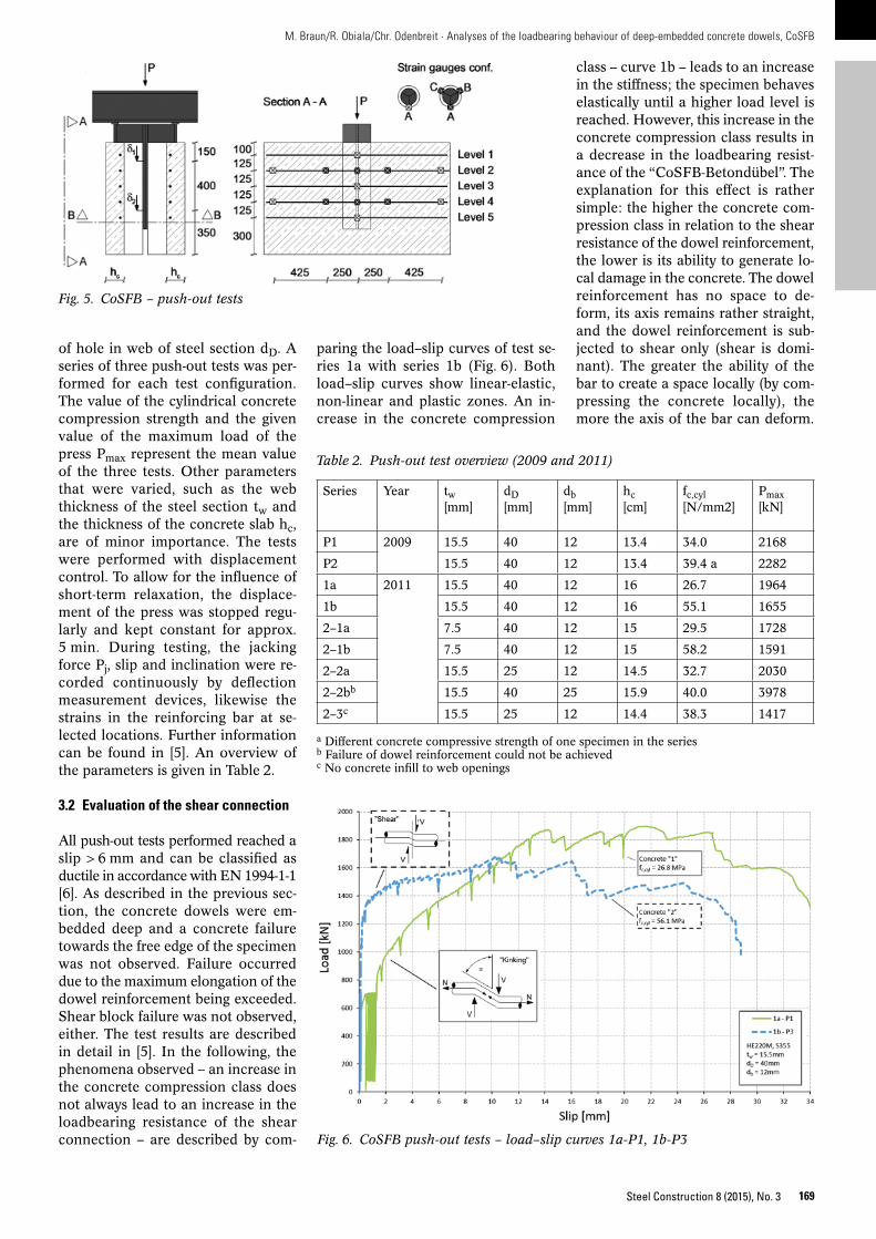
To investigate the characteristics of the shear connection, 27 push-out tests with varied parameters were performed. The test configuration is shown in Fig. 5.
The most important parameters for the loadbearing behaviour and loadbearing resistance are: diameter of dowel reinforcement db, concrete compression class fc,cyl and diameter
with two shear beam tests and two beam tests (Fig. 4). Analyses were fo-cused on the activation of the effective width of the concrete chord, the de-flection and vibration behaviour as well as the overall structural behav-iour. The beam test programme is sum-marized in Table 1. All tests showed a very ductile behaviour with large deformations up to failure. Failure oc-curred due to failure of the concrete at the upper edge of the section – the edge undergoing maximum compres-sion. Close to the load introduction zone, the concrete constricted and parts of the concrete started to spall.
Based on the measured strain dis-tribution, the effective width of the concrete chord at mid-span was recal-
spans of non-composite slim-floor beams are typically limited to about 7 m. Searching to enlarge the range of applications for slim-floor construc-tion, the structural activation of the in situ concrete was analysed. To con-nect the in situ concrete with the steel beam, allowing for composite beam design, the use of traditional shear studs was analysed first. As shown in Fig. 3, shear studs welded to the up-per flange of the SFB would require either a reduction in the steel section or an increase in the slab thickness h, which would not lead to the required gain in stiffness and resistance. There-fore, the use of standard shear studs is less satisfactory.
Hence, to enlarge the range of applications for slim-floor construc-tion via composite beam design, a solution for the shear connection had to be found. It need hardly be men-tioned that no complexity should be introduced into the erection phase of the structure or the fabrication pro-cess.
3 Test campaign3.1 Beam tests
The global behaviour of the compos-ite slim-floor beam was investigated
Fig. 3. Slim-floor beam with shear studs
Fig. 4. CoSFB – beam tests: a) shear and bending tests, b) cross-section, c) long-span beam test
a)
b)
c)
Table 1. Beam test overview
Type Geometrylength × width
ba
[%]Pmax[kN]
Aim
S1 4.0 × 2.5 m 100 1882 Shear force capacity, structural behaviour (loadbearing capacity, effective width of concrete chord)S2 50 1689
B1 8.0 × 2.5 m 100 945 Structural behaviour (loadbearing capacity, effective width of concrete chord), deflec-tion, vibration analysisB2 100 953
a Theoretical degree of shear connection
169
M. Braun/R. Obiala/Chr. Odenbreit · Analyses of the loadbearing behaviour of deep-embedded concrete dowels, CoSFB
Steel Construction 8 (2015), No. 3
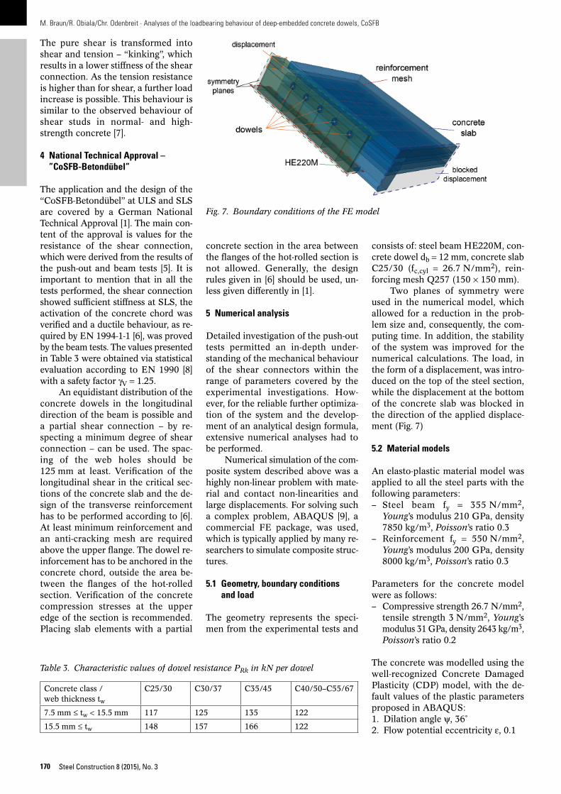
class – curve 1b – leads to an increase in the stiffness; the specimen behaves elastically until a higher load level is reached. However, this increase in the concrete compression class results in a decrease in the loadbearing resist-ance of the “CoSFB-Betondübel”. The explanation for this effect is rather simple: the higher the concrete com-pression class in relation to the shear resistance of the dowel reinforcement, the lower is its ability to generate lo-cal damage in the concrete. The dowel reinforcement has no space to de-form, its axis remains rather straight, and the dowel reinforcement is sub-jected to shear only (shear is domi-nant). The greater the ability of the bar to create a space locally (by com-pressing the concrete locally), the more the axis of the bar can deform.
of hole in web of steel section dD. A series of three push-out tests was per-formed for each test configuration. The value of the cylindrical concrete compression strength and the given value of the maximum load of the press Pmax represent the mean value of the three tests. Other parameters that were varied, such as the web thickness of the steel section tw and the thickness of the concrete slab hc, are of minor importance. The tests were performed with displacement control. To allow for the influence of short-term relaxation, the displace-ment of the press was stopped regu-larly and kept constant for approx. 5 min. During testing, the jacking force Pj, slip and inclination were re-corded continuously by deflection measurement devices, likewise the strains in the reinforcing bar at se-lected locations. Further information can be found in [5]. An overview of the parameters is given in Table 2.
3.2 Evaluation of the shear connection
All push-out tests performed reached a slip > 6 mm and can be classified as ductile in accordance with EN 1994-1-1 [6]. As described in the previous sec-tion, the concrete dowels were em-bedded deep and a concrete failure towards the free edge of the specimen was not observed. Failure occurred due to the maximum elongation of the dowel reinforcement being exceeded. Shear block failure was not observed, either. The test results are described in detail in [5]. In the following, the phenomena observed – an increase in the concrete compression class does not always lead to an increase in the loadbearing resistance of the shear connection – are described by com-
Fig. 5. CoSFB – push-out tests
Table 2. Push-out test overview (2009 and 2011)
Series Year tw[mm]
dD[mm]
db[mm]
hc[cm]
fc,cyl[N/mm2]
Pmax[kN]
P1 2009 15.5 40 12 13.4 34.0 2168
P2 15.5 40 12 13.4 39.4 a 2282
1a 2011 15.5 40 12 16 26.7 1964
1b 15.5 40 12 16 55.1 1655
2–1a 7.5 40 12 15 29.5 1728
2–1b 7.5 40 12 15 58.2 1591
2–2a 15.5 25 12 14.5 32.7 2030
2–2bb 15.5 40 25 15.9 40.0 3978
2–3c 15.5 25 12 14.4 38.3 1417
a Different concrete compressive strength of one specimen in the seriesb Failure of dowel reinforcement could not be achievedc No concrete infill to web openings
Fig. 6. CoSFB push-out tests – load–slip curves 1a-P1, 1b-P3
paring the load–slip curves of test se-ries 1a with series 1b (Fig. 6). Both load–slip curves show linear-elastic, non-linear and plastic zones. An in-crease in the concrete compression
M. Braun/R. Obiala/Chr. Odenbreit · Analyses of the loadbearing behaviour of deep-embedded concrete dowels, CoSFB
170 Steel Construction 8 (2015), No. 3
The pure shear is transformed into shear and tension – “kinking”, which results in a lower stiffness of the shear connection. As the tension resistance is higher than for shear, a further load increase is possible. This behaviour is similar to the observed behaviour of shear studs in normal- and high-strength concrete [7].
4 National Technical Approval – ”CoSFB-Betondübel”
The application and the design of the “CoSFB-Betondübel” at ULS and SLS are covered by a German National Technical Approval [1]. The main con-tent of the approval is values for the resistance of the shear connection, which were derived from the results of the push-out and beam tests [5]. It is important to mention that in all the tests performed, the shear connection showed sufficient stiffness at SLS, the activation of the concrete chord was verified and a ductile behaviour, as re-quired by EN 1994-1-1 [6], was proved by the beam tests. The values presented in Table 3 were obtained via statistical evaluation according to EN 1990 [8] with a safety factor gV = 1.25.
An equidistant distribution of the concrete dowels in the longitudinal direction of the beam is possible and a partial shear connection – by re-specting a minimum degree of shear connection – can be used. The spac-ing of the web holes should be 125 mm at least. Verification of the longitudinal shear in the critical sec-tions of the concrete slab and the de-sign of the transverse reinforcement has to be performed according to [6]. At least minimum reinforcement and an anti-cracking mesh are required above the upper flange. The dowel re-inforcement has to be anchored in the concrete chord, outside the area be-tween the flanges of the hot-rolled section. Verification of the concrete compression stresses at the upper edge of the section is recommended. Placing slab elements with a partial
concrete section in the area between the flanges of the hot-rolled section is not allowed. Generally, the design rules given in [6] should be used, un-less given differently in [1].
5 Numerical analysis
Detailed investigation of the push-out tests permitted an in-depth under-standing of the mechanical behaviour of the shear connectors within the range of parameters covered by the experimental investigations. How-ever, for the reliable further optimiza-tion of the system and the develop-ment of an analytical design formula, extensive numerical analyses had to be performed.
Numerical simulation of the com-posite system described above was a highly non-linear problem with mate-rial and contact non-linearities and large displacements. For solving such a complex problem, ABAQUS [9], a commercial FE package, was used, which is typically applied by many re-searchers to simulate composite struc-tures.
5.1 Geometry, boundary conditions and load
The geometry represents the speci-men from the experimental tests and
consists of: steel beam HE220M, con-crete dowel db = 12 mm, concrete slab C25/30 (fc,cyl = 26.7 N/mm2), rein-forcing mesh Q257 (150 × 150 mm).
Two planes of symmetry were used in the numerical model, which allowed for a reduction in the prob-lem size and, consequently, the com-puting time. In addition, the stability of the system was improved for the numerical calculations. The load, in the form of a displacement, was intro-duced on the top of the steel section, while the displacement at the bottom of the concrete slab was blocked in the direction of the applied displace-ment (Fig. 7)
5.2 Material models
An elasto-plastic material model was applied to all the steel parts with the following parameters: – Steel beam fy = 355 N/mm2,
Young’s modulus 210 GPa, density 7850 kg/m3, Poisson’s ratio 0.3
– Reinforcement fy = 550 N/mm2, Young’s modulus 200 GPa, density 8000 kg/m3, Poisson’s ratio 0.3
Parameters for the concrete model were as follows: – Compressive strength 26.7 N/mm2,
tensile strength 3 N/mm2, Young’s modulus 31 GPa, density 2643 kg/m3, Poisson’s ratio 0.2
The concrete was modelled using the well-recognized Concrete Damaged Plasticity (CDP) model, with the de-fault values of the plastic parameters proposed in ABAQUS:1. Dilation angle ψ, 36˚2. Flow potential eccentricity e, 0.1
Table 3. Characteristic values of dowel resistance PRk in kN per dowel
Concrete class /web thickness tw
C25/30 C30/37 C35/45 C40/50–C55/67
7.5 mm ≤ tw < 15.5 mm 117 125 135 122
15.5 mm ≤ tw 148 157 166 122
Fig. 7. Boundary conditions of the FE model
171
M. Braun/R. Obiala/Chr. Odenbreit · Analyses of the loadbearing behaviour of deep-embedded concrete dowels, CoSFB
Steel Construction 8 (2015), No. 3
5.5 Preliminary results
The aim of this ongoing research is to develop a model suitable for simulat-ing the behaviour of the CoSFB sys-tem, especially local behaviour and the failure modes of the shear connection. The model will be validated with the results of the experimental tests, where different sections for the beam and dif-ferent concrete grades were used.
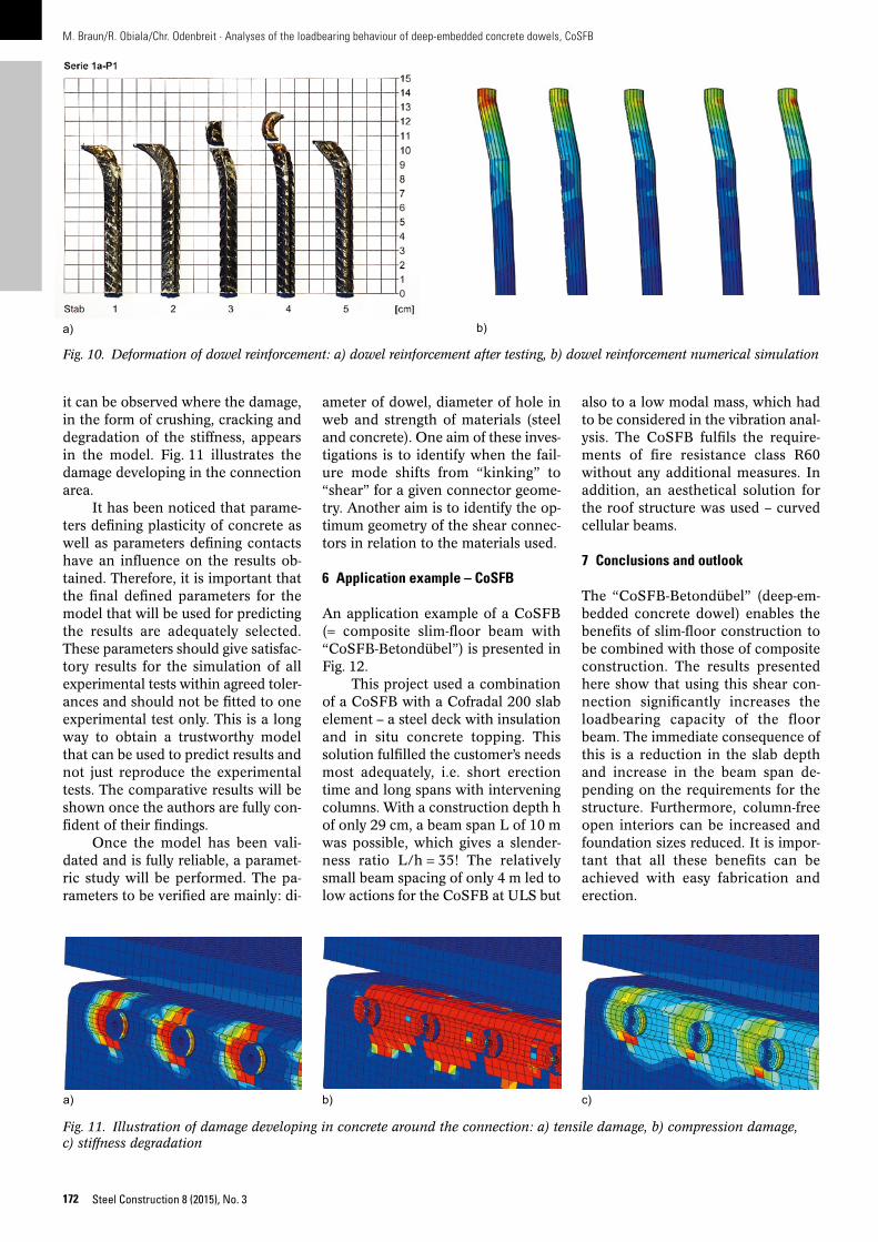
The authors of the paper are at the very beginning of the process. So far, a model representing experimen-tal test “1a” has been prepared, with the specifications described above, to simulate the test. In this test the con-crete model was relatively soft, allow-ing for greater deformation of the bars and creating the “kinking” effect. The deformed shape of the dowels ob-tained from the simulation is compa-rable with the shape of the dowels observed in the experimental test as illustrated in Fig. 10.
Owing to the use of the material concrete model with damage (CPD),
a)
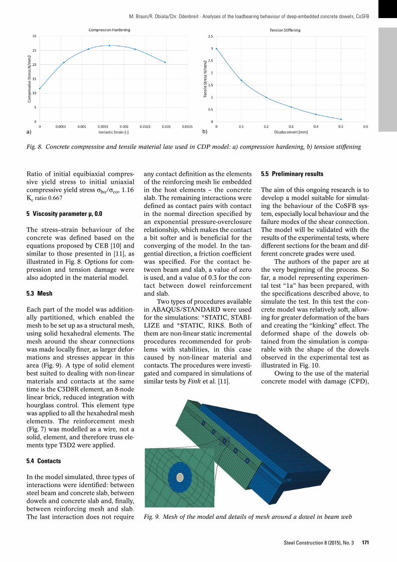
Fig. 8. Concrete compressive and tensile material law used in CDP model: a) compression hardening, b) tension stiffening
b)
Fig. 9. Mesh of the model and details of mesh around a dowel in beam web
Ratio of initial equibiaxial compres-sive yield stress to initial uniaxial compressive yield stress σbo/σco, 1.16Kc ratio 0.667
5 Viscosity parameter μ, 0.0
The stress–strain behaviour of the concrete was defined based on the equations proposed by CEB [10] and similar to those presented in [11], as illustrated in Fig. 8. Options for com-pression and tension damage were also adopted in the material model.
5.3 Mesh
Each part of the model was addition-ally partitioned, which enabled the mesh to be set up as a structural mesh, using solid hexahedral elements. The mesh around the shear connections was made locally finer, as larger defor-mations and stresses appear in this area (Fig. 9). A type of solid element best suited to dealing with non-linear materials and contacts at the same time is the C3D8R element, an 8-node linear brick, reduced integration with hourglass control. This element type was applied to all the hexahedral mesh elements. The reinforcement mesh (Fig. 7) was modelled as a wire, not a solid, element, and therefore truss ele-ments type T3D2 were applied.
5.4 Contacts
In the model simulated, three types of interactions were identified: between steel beam and concrete slab, between dowels and concrete slab and, finally, between reinforcing mesh and slab. The last interaction does not require
any contact definition as the elements of the reinforcing mesh lie embedded in the host elements – the concrete slab. The remaining interactions were defined as contact pairs with contact in the normal direction specified by an exponential pressure-overclosure relationship, which makes the contact a bit softer and is beneficial for the converging of the model. In the tan-gential direction, a friction coefficient was specified. For the contact be-tween beam and slab, a value of zero is used, and a value of 0.3 for the con-tact between dowel reinforcement and slab.
Two types of procedures available in ABAQUS/STANDARD were used for the simulations: *STATIC, STABI-LIZE and *STATIC, RIKS. Both of them are non-linear static incremental procedures recommended for prob-lems with stabilities, in this case caused by non-linear material and contacts. The procedures were investi-gated and compared in simulations of similar tests by Fink et al. [11].
M. Braun/R. Obiala/Chr. Odenbreit · Analyses of the loadbearing behaviour of deep-embedded concrete dowels, CoSFB
172 Steel Construction 8 (2015), No. 3
it can be observed where the damage, in the form of crushing, cracking and degradation of the stiffness, appears in the model. Fig. 11 illustrates the damage developing in the connection area.
It has been noticed that parame-ters defining plasticity of concrete as well as parameters defining contacts have an influence on the results ob-tained. Therefore, it is important that the final defined parameters for the model that will be used for predicting the results are adequately selected. These parameters should give satisfac-tory results for the simulation of all experimental tests within agreed toler-ances and should not be fitted to one experimental test only. This is a long way to obtain a trustworthy model that can be used to predict results and not just reproduce the experimental tests. The comparative results will be shown once the authors are fully con-fident of their findings.
Once the model has been vali-dated and is fully reliable, a paramet-ric study will be performed. The pa-rameters to be verified are mainly: di-
ameter of dowel, diameter of hole in web and strength of materials (steel and concrete). One aim of these inves-tigations is to identify when the fail-ure mode shifts from “kinking” to “shear” for a given connector geome-try. Another aim is to identify the op-timum geometry of the shear connec-tors in relation to the materials used.
6 Application example – CoSFB
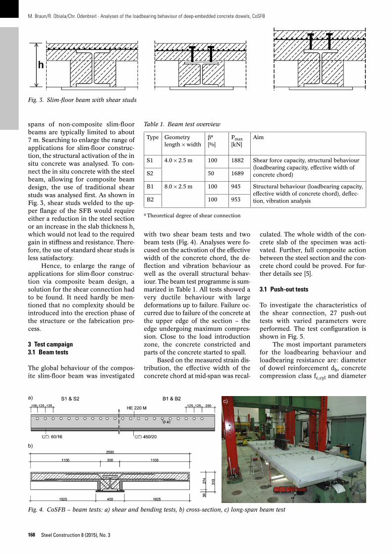
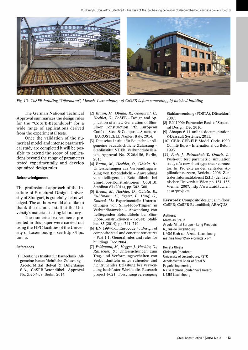
An application example of a CoSFB (= composite slim-floor beam with “CoSFB-Betondübel”) is presented in Fig. 12.
This project used a combination of a CoSFB with a Cofradal 200 slab element – a steel deck with insulation and in situ concrete topping. This solution fulfilled the customer’s needs most adequately, i.e. short erection time and long spans with intervening columns. With a construction depth h of only 29 cm, a beam span L of 10 m was possible, which gives a slender-ness ratio L/h = 35! The relatively small beam spacing of only 4 m led to low actions for the CoSFB at ULS but
also to a low modal mass, which had to be considered in the vibration anal-ysis. The CoSFB fulfils the require-ments of fire resistance class R60 without any additional measures. In addition, an aesthetical solution for the roof structure was used – curved cellular beams.
7 Conclusions and outlook
The “CoSFB-Betondübel” (deep-em-bedded concrete dowel) enables the benefits of slim-floor construction to be combined with those of composite construction. The results presented here show that using this shear con-nection significantly increases the loadbearing capacity of the floor beam. The immediate consequence of this is a reduction in the slab depth and increase in the beam span de-pending on the requirements for the structure. Furthermore, column-free open interiors can be increased and foundation sizes reduced. It is impor-tant that all these benefits can be achieved with easy fabrication and erection.
Fig. 10. Deformation of dowel reinforcement: a) dowel reinforcement after testing, b) dowel reinforcement numerical simulation
a) b)
Fig. 11. Illustration of damage developing in concrete around the connection: a) tensile damage, b) compression damage, c) stiffness degradation
a) b) c)
173
M. Braun/R. Obiala/Chr. Odenbreit · Analyses of the loadbearing behaviour of deep-embedded concrete dowels, CoSFB
Steel Construction 8 (2015), No. 3
Stahlanwendung (FOSTA), Düsseldorf, 2007.
[8] EN 1990: Eurocode: Basis of Structu-ral Design, Dec 2010.
[9] Abaqus 6.11 online documentation, ©Dassault Systèmes, 2011.
[10] CEB: CEB-FIP Model Code 1990. Comité Euro – International du Beton, 1993.
[11] Fink, J., Petraschek T., Ondris, L.: Push-out test parametric simulation study of a new sheet-type shear connec-tor. In: Projekte an den zentralen Ap-plikationsservern, Berichte 2006, Zen-traler Informatikdienst (ZID) der Tech-nischen Universität Wien pp. 131–153, Vienna, 2007, http://www.zid.tuwien.ac.at/projekte.
Keywords: Composite design; slim-floor; CoSFB; CoSFB-Betondübel; ABAQUS
Authors:Matthias BraunArcelorMittal Europe – Long Products66, rue de LuxembourgL-4009 Esch-sur-Alzette, [email protected]
Renata Obiala Christoph OdenbreitUniversity of Luxembourg, FSTCArcelorMittal Chair of Steel & Façade Engineering6, rue Richard Coudenhove KalergiL-1359 Luxembourg
[2] Braun, M., Obiala, R., Odenbreit, C., Hechler, O.: CoSFB – Design and Ap-plication of a new Generation of Slim-Floor Construction. 7th European Conf. on Steel & Composite Structures (EUROSTEEL), Naples, Italy, 2014.
[3] Deutsches Institut für Bautechnik: All-gemeine bauaufsichtliche Zulassung – Stahlinstitut VDEh, Verbunddübelleis-ten. Approval No. Z-26.4-56, Berlin, 2013.
[4] Braun, M., Hechler, O., Obiala, R.: Untersuchungen zur Verbundtragwir-kung von Betondübeln – Anwendung von tiefliegenden Betondübeln bei Slim-Floor-Konstruktionen (CoSFB). Stahlbau 83 (2014), pp. 302–308.
[5] Braun, M., Hechler, O., Obiala, R., Kuhlmann, U., Eggert, F., Hauf, G., Konrad, M.: Experimentelle Untersu-chungen von Slim-Floor-Trägern in Verbundbauweise – Anwendung von tiefliegenden Betondübeln bei Slim-Floor-Konstruktionen – CoSFB. Stahl-bau 83 (2014), pp. 741–749.
[6] EN 1994-1-1: Eurocode 4: Design of composite steel and concrete structures – Part 1-1: General rules and rules for buildings, Dec 2004.
[7] Feldmann, M., Hegger, J., Hechler, O., Rauscher, S.: Untersuchungen zum Trag- und Verformungsverhalten von Verbundmitteln unter ruhender und nichtruhender Belastung bei Verwen-dung hochfester Werkstoffe. Research project P621. Forschungsvereinigung
The German National Technical Approval summarizes the design rules for the “CoSFB-Betondübel” for a wide range of applications derived from the experimental tests.
Once the validation of the nu-merical model and intense parametri-cal study are completed it will be pos-sible to extend the scope of applica-tions beyond the range of parameters tested experimentally and develop optimized design rules.
Acknowledgments
The professional approach of the In-stitute of Structural Design, Univer-sity of Stuttgart, is gratefully acknowl-edged. The authors would also like to thank the technical staff at the Uni-versity’s materials-testing laboratory.
The numerical experiments pre-sented in this paper were carried out using the HPC facilities of the Univer-sity of Luxembourg – see http://hpc.uni.lu.
References
[1] Deutsches Institut für Bautechnik: All-gemeine bauaufsichtliche Zulassung – ArcelorMittal Belval & Differdange S.A., CoSFB-Betondübel. Approval No. Z-26.4-59, Berlin, 2014.
Fig. 12. CoSFB building “Offermann”, Mersch, Luxembourg: a) CoSFB before concreting, b) finished building
a) b)