Analog and Digital Inclination Sensors Instruction Manual · Analog and Digital Inclination Sensors...
40
POSITILT ® - PTAM / PTDM Analog and Digital Inclination Sensors Instruction Manual Please read carefully before installation and operation!
Transcript of Analog and Digital Inclination Sensors Instruction Manual · Analog and Digital Inclination Sensors...

POSITILT® - PTAM / PTDMAnalog and DigitalInclination Sensors
Instruction Manual
Please read carefully before installation and operation!

2 MAN-PT-E-15 ASM GmbH
www.asm-sensor.com
POSITILT®
Contents
Contents Safety instructions 3Intended use 4Unintended use 4Maintenence, service, deinstallation, disposal 4Description 5Electrical installation 6Mounting 6 Torque for the mounting screws 6 Outline drawings 6Accessories 11 Mounting plates 11PTAM - Analog output specification 12PTDM - CANopen output specification 14PTDM - CANopen output - set up procedure 15PTDM - CAN SAE J1939 output specification 25PTDM - CAN SAE J1939 output - set up procedure 26Output characteristics 34Response time 36Service, calibartion, disposal 37Reliability characteristics 38Declaration of conformity 39

ASM GmbH MAN-PT-E-15 3
www.asm-sensor.com
POSITILT®
Warranty reference
Safety instructions
Do not use POSIROT® position sensors in safety critical appli-cations where malfunction or total failure of the sensor may cause danger for man or machine.
For safety related applications additional mechanisms (de-vices) are necessary to maintain safety and to avoid damage.
Disregard of this advice releases the manufacturer from pro-duct liability.
The sensor must be operated only within values specified in the catalog or datasheet.
Connection to power supply must be performed in accordance with safety instructions for electrical facilities and performed only by trained staff.
Explanation of used safety signs and signal words
WARNING, Risk of Injury: Indicates a potentially hazardous situation, which, if not avoided, could result in serious injury or property damage.
WARNING, Risk of Personal Injury or Death: Indicates a situation that can result in serious personal injury or death if not properly avoided.
DANGER
WARNING, Risk of Personal Injury or Death: Indicates a situation that can result in moderate personal injury or death if not properly avoided.
WARNING
WARNING, Risk of Personal Injury: Indicates a situation that can result in minor personal injury if not properly avoided.
CAUTION
WARNING, Risk of Property Damage: Indicates a situation that can result in minor to major property damage if not properly avoided.
NOTICE

4 MAN-PT-E-15 ASM GmbH
www.asm-sensor.com
POSITILT®
Instruction Manual
Intended use
Unintended use
Maintenance and service
• In order to avoid risk of injury and improper handling the customer is not allowed to repair the sensor. No warranty or liability will be granted for opened sensors.
• Damaged sensors must be shut down immediately and sent to the factory for repair.
Proper maintenance comprises the visual examination od parts (e.g. inte-grity of housing, connectors and cables). Maintenance intervals depend on thespecificapplicationandshouldbedefinedbytheuserindependanceof operating conditions.
The following maintenance steps are recommended:
Maintenance- interval
CAUTION
Integrity of housing, connector, cable Mounting elements
PTAM2/PTDM2 X X
PTAM5/PTDM5 X X
PTAM27/PTDM27 X X
Measures Damaged parts: put sensor out of service, replace damaged parts resp. send sensor to ASM for repair
Loose mounting parts:Screw tight mounting parts with recommended torque, if applica-ble use screw protections
Deinstallation Disconnectelectricalconnections.Loosenfixingscrews.
Disposal Disposal according to applicable government regulations.
The angle sensor was intended for angular position measurement, when properly mounted and used in the specified ambientatmospheric and technical conditions for which the sensor is designated.
Theunintendeduseiswhenthesensorisusedoutsideitsspecifiedtechnical and ambient atmospheric conditions or when incorrectly mounted.

ASM GmbH MAN-PT-E-15 5
www.asm-sensor.com
POSITILT®
Description
Description Tilt sensors of the POSITILT product family measure the angle of inclina-tionforoneortwoaxes.Measuringrangecanbespecifiedfrom±15upto±180degree.Outputconfigurationcompriseshighresolutionvoltageorcurrent output and CAN interface. A wide variety of package and mounting optionsprovideflexibilityformanyapplications.
The home (center) position of the inclinometers POSITILTcanbeconfigu-rated not only via the mechanical adjustment but also via a switching input (Teach-In)whentheconnectorpinZEROisconnectedto0V(GND)for2seconds.
Mounting options
Home position(optional)

6 MAN-PT-E-15 ASM GmbH
www.asm-sensor.com
Supply voltage, current consumption, wiringFor wiring of connector or cable outlet as well as supply voltage and current consumptionrefertochapter„Outputspecification“.Cable screen has to be connected to protective earth.
Caution: Observe different color code for pre-assembled accessory cables - refer to accessories pages.The protection class of sensors with connector output is valid only if the electrical plug is connected!Caution: Do not twist the M12 connector insert.Cable outputs must be installed in such a way that no moisture can get into the cable.Crossing the dew point must be avoided.
Electrical installation
POSITILT®
Electrical installation
TorqueMounting method Torque
[Nm]
M2,5 screws for mounting brackets (PTAM2) 0.8
M8screws(PTAM5) <10
Screws M4 with washer (PTAM27) <2
Mounting
Mechanical information PTAM27, PTDM27
• Mountthesensoronaflatsurface.
• Do not deform the sensor housing!
• Lateral inclination sensitivity:
• Upto30°lateralinclinationtheresultingerroris≤1°.

ASM GmbH MAN-PT-E-15 7
www.asm-sensor.com
POSITILT®
Mounting, Outline drawings
Outline drawing PTAM2/PTDM2 Connector version M12 axial
Dimensions informative only.For guaranteed dimensions consult factory.
Dimensions in mm [inch]
Marking
Connector M12

8MAN-PT-E-15 ASMGmbH
www.asm-sensor.com
POSITILT®
Outline drawings
Outline drawing PTAM2/PTDM2 Connector version M12 radial
Dimensions informative only.For guaranteed dimensions consult factory.
Dimensions in mm [inch]
MarkingConnector M12

20[.
787]
48
0,051.890
.002
[
]
66 - 0,10+ 2.598 - .004
0+
[ ]
9 [.354]Ø
15 [.591]Ø
10[.
394]
13 [.512]
M12-Stecker
Markierung
10[.
394]
34[1
.339
]
20[.
787]
M12-Stecker
15 [.591]
9 [.354]Ø
10[.
394]
66
- 0,10+
2.598- .004
0+[
]48 0,05 1.890.002
[]
Markierung
ASM GmbH MAN-PT-E-15 9
www.asm-sensor.com
POSITILT®
Outline drawings
Outline drawing PTAM5/PTDM5 Connector version M12 axial
Dimensions in mm [inch]
Marking
Connector M12
Outline drawing PTAM5/PTDM5 Connector version M12 radial
Marking
Connector M12
22 [.866]
38 [1.496]
49,50,1 1.949.004[ ]
45,5
[1.7
91]
30[1
.181
]
10 [.394]
7,8
[.30
7]Ø
5[.
197]
Ø
18,2
[.71
7]
60°
5,2 [.205]
5 [.197]
R6,3 [.248]
Kabel / cable
10MAN-PT-E-15 ASM GmbH
www.asm-sensor.com
POSITILT®
Outline drawings
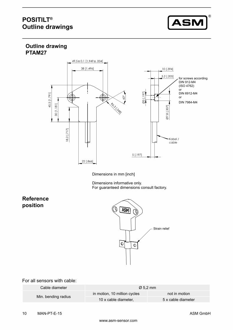
Outline drawing PTAM27
Dimensions informative only.For guaranteed dimensions consult factory.
Dimensions in mm [inch]
Reference position
Cable diameter Ø 5,2 mm
Min. bending radiusinmotion,10millioncycles not in motion
10xcablediameter, 5 x cable diameter
For all sensors with cable:
Strain relief
for screws accordingDIN 912-M4(ISO 4762)orDIN 6912-M4 orDIN7984-M4

33 [1.299]Ø
42 [1.654]
4 [.157]
55 [2.165]
3x M2,5
4[.
157]
90°
110°
3x M4
48 [1.890]
33 [1.299]Ø
40 [1.575]
40[1
.575
]
42 [1.654]
5,5[.2
17]
5[.
197]
4 [.157]
55 [2.165]
3x M2,5
4[.
157]
90°
110°
3x M4
48 [1.890]
ASM GmbH MAN-PT-E-15 11
www.asm-sensor.com
Mounting plate PRPT-BPL1 (screw mounting) for PTAM2/PTDM2
Mounting plate PRPT-BPL2 (welding assembly) for PTAM2/PTDM2
Dimensions in mm [inch]
Dimensions informative only.For guaranteed dimensions consult factory.
POSITILT®
Mounting plates
12 MAN-PT-E-15 ASM GmbH
www.asm-sensor.com
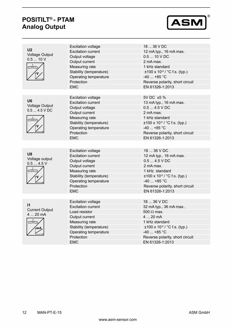
POSITILT® - PTAMAnalog Output
U2 VoltageOutput 0.5...10V
Excitation voltage 18...36VDCExcitation current 12 mA typ., 16 mA max.Output voltage 0.5...10VDCOutput current 2 mA max.Measuring rate 1 kHz standardStability (temperature) ±100x10-6/°Cf.s.(typ.)Operating temperature -40...+85°CProtection Reverse polarity, short circuitEMC EN61326-1:2013
U6 VoltageOutput0.5...4.5VDC
Excitation voltage 5VDC±5%Excitation current 13 mA typ., 16 mA max.Output voltage 0.5...4.5VDCOutput current 2 mA max.Measuring rate 1 kHz standardStability (temperature) ±100x10-6/°Cf.s.(typ.)Operating temperature -40...+85°CProtection Reverse polarity, short circuitEMC EN61326-1:2013
I1 Current Output4...20mA
Excitation voltage 18...36VDCExcitation current 32 mA typ., 36 mA max..Load resistor 500Ω max.Output current 4...20mAMeasuring rate 1 kHz standardStability (temperature) ±100x10-6/°Cf.s.(typ.)Operating temperature -40...+85°CProtection Reverse polarity, short circuitEMC EN61326-1:2013
U8 Voltageoutput 0.5...4.5V
Excitation voltage 18...36VDCExcitation current 12 mA typ., 16 mA max.Output voltage 0.5...4.5VDCOutput current 2 mA max.Measuring rate 1 kHz standardStability (temperature) ±100x10-6/°Cf.s.(typ.)Operating temperature -40...+85°CProtection Reverse polarity, short circuitEMC EN61326-1:2013

ASM GmbH MAN-PT-E-15 13
www.asm-sensor.com
POSITILT® - PTAMAnalog Output, programmable
U2/PMZ VoltageOutput 0.5...10V
Excitation voltage 18...36VDCExcitation current 12 mA typ., 16 mA max.Output voltage 0.5...10VDCOutput current 2 mA max.Measuring rate 1 kHz standardStability (temperature) ±100x10-6/°Cf.s.(typ.)Operating temperature -40...+85°CProtection Reverse polarity, short circuitEMC EN61326-1:2013
I1/PMZ Current Output4...20mA
Excitation voltage 18...36VDCExcitation current 32 mA typ., 36 mA max..Load resistor 500Ω max.Output current 4...20mAMeasuring rate 1 kHz standardStability (temperature) ±100x10-6/°Cf.s.(typ.)Operating temperature -40...+85°CProtection Reverse polarity, short circuitEMC EN61326-1:2013
U8/PMZ Voltageoutput 0.5...4.5V
Excitation voltage 18...36VDCExcitation current 12 mA typ., 16 mA max.Output voltage 0.5...4.5VDCOutput current 2 mA max.Measuring rate 1 kHz standardStability (temperature) ±100x10-6/°Cf.s.(typ.)Operating temperature -40...+85°CProtection Reverse polarity, short circuitEMC EN61326-1:2013
Programming the zero point by the customer:Thefunction„ZERO“allowstoprogramthezeropointoftheoutputrangeby using a signal ZERO available at the connector. This Signal ZERO must beconnectedwithGNDviaapushbutton(Teach-In).Atfirst the sensormust be brought into the zero position. Pushing the button 2 seconds sets the actual position as the zero point. The values are available as well after switching off the sensor.
Function ZERO (Option) U2/PMZ U8/PMZI1/PMZ
M12A5 / M12R5
14 MAN-PT-E-15 ASM GmbH
www.asm-sensor.com
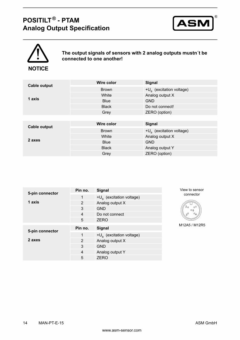
5-pin connector 2 axes
Pin no. Signal1 +UB (excitation voltage)2 Analog output X 3 GND4 Analog output Y5 ZERO
Viewtosensorconnector
POSITILT ® - PTAMAnalog Output Specification
Cable output
1 axis
Wire color SignalBrown +UB (excitation voltage)White Analog output XBlue GNDBlack Do not connect!Grey ZERO (option)
Cable output
2 axes
Wire color SignalBrown +UB (excitation voltage)White Analog output XBlue GNDBlack Analog output YGrey ZERO (option)
5-pin connector 1 axis
Pin no. Signal1 +UB (excitation voltage)2 Analog output X 3 GND4 Do not connect5 ZERO
The output signals of sensors with 2 analog outputs mustn´t be connected to one another!
NOTICE

CANopen InterfaceCommunicationprofile CANopenCiA301V4.02,SlaveDeviceprofile InclinometerCiA410V1.2Configurationservices LSS,CiADraftStandard305(transmissionrate,
node ID)Error Control Node Guarding, Heartbeat, Emergency MessageNode ID Adjustable via LSS or via object dictionary;
default: 127PDO 1TxPDO,0RxPDO,staticmappingPDO Modes Event-/Time triggered, Remote-request, Sync
cyclic/acyclicSDO 1Server,0ClientCertified YesBit rate 50kBaudto1MBaud,adjustableviaLSSorvia
object dictionary, default: 125 kBaudBus connection M12 connector, 5 pinIntegrated Bus termination resistor PTDM27only,configurable
Bus, galvanic isolation No
ASM GmbH MAN-PT-E-15 15
www.asm-sensor.com
InclinationsensorwithCANopeninterfaceaccordingtoCiA410.
SpecificationsExcitation voltage 8...36VDCExcitation current 15mAtypicalat24VDC,
30mAtypicalat12VDC,100mAmax.Measuring rate 1 kHz standardStability (temperature) ±100x10-6/°Cf.s.Repeatability 1 LSBOperating temperature -40...+85°CProtection Reverse polarity, short circuitEMC EN61326-1:2013
Description
POSITILT® - PTDMCANopen Output Specification

16 MAN-PT-E-15 ASM GmbH
www.asm-sensor.com
POSITILT® - PTDMCANopen Output - set up procedure
Warning notice• Changing parameters may cause unexpected machine movement. • Changingparametersmayinfluencedependentparameters• e.g. changing the resolutionmayhave influenceonpositionofCAM
switches. • Precautions have to be taken to avoid damage to human and machine
parts! • Change parameters only when machine is in a safe condition!
Before connecting the sensor to the CAN-Bus the devices have to be che-ckedforcorrectbitrateanduniquenode-IDs.Bothparametersareconfi-gurable by Layer-Setting-Service (LSS) or by Service Data Object (SDO). After power-on the sensor will enter pre-operational state and send a boot-upmessagebeingreadyforconfigurationbyServiceDataObjects.Para-metersconfiguredbytheusercanbestorednonvolatilebySAVEcommand.Onreceiving„NMT-Node-Start“thesensortransitstooperationalstateandstartsprocessdatatransmission.When„Auto-Start“isconfiguredthesen-sor will automatically transit to operational after boot-up without a need for the Node-Start message.
Node monitoring is supported by Node Guarding and Heartbeat protocol. Node Guarding implements cyclic querying of the node status by the NMT-Master within the guard time window. The Heartbeat protocol provides au-tomatic transmission of the node status (heartbeat message) by the slave within producer heartbeat time window. Following the CAN example protocols included in this manual the sensor may be used without CANopen master device.
Setup
WARNING
NOTICE

COB-Id DLCByte0
Data FrameByte7
180h+Node-Id length DataFramemax8Byte
SDO COB-Id Default COB-Id
Master to Slave 600h+Node-Id 67Fh
Slave to Master 580h+Node-Id 5FFh
Transmission typeexample for TPDO-1
COB-Id1800-1
Transmission Type1800-2
Inhibit Time1800-3
Event Timer [ms]1800-5
Cyclic Asynchronous FEh 1..07FFFh 1..07FFFh
Change of State FEh 1..07FFFh 0
Synchronous N=1..240 -
TPDO Disable 8000xxxx - -
TPDO Enable 0000xxxx
ASM GmbH MAN-PT-E-15 17
www.asm-sensor.com
POSITILT® - PTDMCANopen Output Specification
Service Data Object (SDO) COB-Id
Service data objects (SDO) provide a peer to peer communication between master and slave. The communicationobjectidentifier(COB)oftheSDOisdefinedbytheNode-Id.
Process Data Object (TPDO)
RealtimedatatransferisprovidedbyProcessDataObjects(PDO).ThePDOmappingisfixed.ThePDOCOB-IdisbydefaultsettingderivedfromtheNode-Id(PredefinedConnectionSet)butmaybechangedtoapplicationspecificvaluesbyPDOCOB-Id1800-1,1801-1,....DLCdefinesthelengthofthedatafield.
TransmissionbehaviourofTPDO-1,-2,-4isconfigurablebyCommunicationParameterPDOCOB-Id1800,1801,...sub-indices-1,-2,-3and-5.
Transmission type «cyclic asynchronous» triggers TPDO-transmission periodically with a time perioddefinedbytheeventtimer.Transmissiontype«changeofstate»willbeenabledIftheeventtimerissetto«0».ThiswilltriggerTPDO-transmissiononchangeofthepositionvaluewhere«Inhibittime»definesaminimumtimedelay between consecutive TPDOs.In «synch mode» a TPDO is transmitted on reception of a number of one or multiple SYNC commands. EnableordisableaTPDObysettingBit31oftheCOB-Id‘0’resp.‘1’(Default:«0»Enabled).

Object Dictionary Communication Profile CiA 301
Object Index [hex]
Sub-index Access Type Default Value Range /
Note
Device type 1000 0 ro U32 2019Ah inclinometerprofile‚410
Error register 1001 0 ro U8 0
COB-ID-Sync 1005 0 rw U32 80
Manufacturer device name 1008 0 ro String -
Manufacturer hardware version 1009 0 ro String -
Manufacturer software version 100A 0 ro String -
Guard time 100C 0 rw U16 0 0..7FFFhLife time factor 100D 0 rw U8 0 0..FFhSave Settings 1010 1 w U32 - „save“65766173hLoad Manufacturer Settings 1011 1 w U32 - „load“64616F6Ch*)
COB-ID-EMCY 1014 0 ro U32 FFh NodeID+80hProducer heartbeat time 1017 0 rw U16 0 0..7FFFhIdendityObjectVendorID 1018 1 ro U32 252h
Idendity Object Product Code 2 ro U32 -Idendity Object Revision number 3 ro U32 -
Idendity Object Serial number 4 ro U32 -COB-ID Server->Client 1200 1 ro U32 67Fh - SODCOBID Client-> Sever 1200 2 ro U32 5FFh - SDOPDO1 COB-ID 1800 1 rw U32 1FFh 181h..1FFhPDO1 Transmission-Type 2 rw U8 FEh 0..FFh
PDO1 Inhibit time 3 rw U16 0 0..7FFFh
PDO1 Event timer 5 rw U16 0 0..7FFFh
TPDO1-Mapped Object 1 1A00 1 ro U32 60100010h
TPDO1-Mapped Object 2 2 ro U32 60200010hNMT-Startup 1F80 0 rw U32 0 0,8
18MAN-PT-E-15 ASM GmbH
www.asm-sensor.com
POSITILT® - PTDMCANopen Output Specification
*)ResetintodefaultsettingsexceptBitrateandNodeID.

Operating Parameters Bit Code7 ... 2 1 0m s cs
MSB LSB
cs=0/1 CodesequenceCW/CCWs=0/1 Scalingfunctionenabled/disabledm=0/1 Operatingmode:1axisx±180°/2axesx,y±60°
Device Profile
Object Index [hex]
Sub-index Access Type Default Value Range /
NoteManufacturer specificNode-ID 2000 rw 127 1…127Bitrate 2010 rw 4 0..4,6Error 2030 ro
Hysteresis 2040 rw
Bus termination 2050 0 0:OFF,1:ON(PTDM27 only)
Filter (NFilter)ResponseTime(90%):TR = NFilter*5ms
2102 rw 16 0...65535
Inclinometer CiA410Resolution(in0,001°) 6000 rw 100 10...10000Slope long16 inclination angle round x axis 6010
Oper. parameters slope long16, 1 or 2 axes 6011 0
Slope long16 preset value 6012 0Slope lateral16 inclination angle round y axis 6020
Oper. parameters slope lateral16, 2nd axis 6021 0
Slope lateral16 preset value 6022 0
ASM GmbH MAN-PT-E-15 19
www.asm-sensor.com
POSITILT® - PTDMCANopen Output Specification

Baud Rate (Object 2010)
Bitrate Index Bitrate [kbit/s]0 10001 8002 5003 2504 1256 50
Process Data Object (TPDO) Mapping
TPDO COB-Id DLCByte0
Data FrameByte7
TPDO-01 180h+Node-Id 4
4 Byte Inclination Data
LSBX MSBX LSBY MSBY
TPDO Default Settings
TPDO Default COB-Id Default Transmission TypeTPDO-01:PositionData,4Byte 1FFh Event Mode (FE)
20MAN-PT-E-15 ASM GmbH
www.asm-sensor.com
POSITILT® - PTDMCANopen Output Specification

ASM GmbH MAN-PT-E-15 21
www.asm-sensor.com
POSITILT® - PTDMCANopen Output Specification
Examples Example protocols are prepared using the IXXAT USB-to-CAN PC-Interface with CAN-Monitor „mi-niMon“(IXXATAutomationGmbH,D-88250Weingarten).Theseexamplesenabletheusertocon-figureandtoruntheCANopenslavesfromahostPCwithoutusingaCANopenmasterECU.TheminiMon-screenhastheconfigurationandstatuswindowatleftside,areceivemessagewindowanda transmit message window below.
Configuration Exemple 1 - screenshot

22 MAN-PT-E-15 ASM GmbH
www.asm-sensor.com
Configuration Example 2 - screenshot
Configuration Example 1 - detailed explanation
The example shows the Sensor responding on POWER ON with the Boot-Up message. By SDO messagethenode-Idandthebitratewillbechangedto7Ehand1000kbit/s.FinallythehostsendsanSDO„SAVE“tostoretheconfigurationnonvolatile.
Note: Changes of of node-Id and bit rate will become effective on next POWER ON sequence. So theSAVEcommandhastoaddresstheoldSDO-COB-Id.
Screen Shot Explanation:
Boot-Up messageSet node Id to 7EhResponseSet baud rate to 1000 kbit/sResponseSAVEResponse
POSITILT® - PTDMCANopen Output Specification

ASM GmbH MAN-PT-E-15 23
www.asm-sensor.com
POSITILT® - PTDMCANopen Output Specification
Configuration Example 2 - detailed explanation
The message window shows the slave responding on POWER ON with the Boot-Up messageonnewnode-id7Eh.EventtimerofPDO1ischangedto500msandCOB-IdofPDO1ischangedto1F1h.Finally„Autostart“isactivated(automatictransitiontooperational)andtheconfigurationstorednonvolatilewith„SAVE“.OnPOWEROFF/POWER ON the slave starts sending PDOs asynchronously with the new COB-Id after the Boot-Up message.
Screenshot explanation:
Boot-Up MessageSet PDO1 Event Timer 500ResponseSet PDO1 COB-Id to 1F1ResponseSet AutostartResponseSAVEResponse .. POWER OFFBoot Up on POWER ONCyclic PDO Transfer on Power On.....................

24 MAN-PT-E-15 ASM GmbH
www.asm-sensor.com
POSITILT® - PTDMCANopen Output Specification
ViewtosensorconnectorSignal wiring /
connection
Signal Plug connection Cable connectionShield 1 braidExcitation+ 2 brownGND 3 whiteCAN-H 4 blueCAN-L 5 black
CAN bus wiring
Connect the device by a T-connector to the CAN trunk line. Total length of stubs should be minimized. Do not usesinglestublineslongerthan0.5m.Connectterminatingresistors120Ohmatbothendsofthetrunkline.
TerminationResistor T-Piece CAN bus cable
Sensor

Interface J1939CANspecification ISO11898,BasicandFullCAN2.0BTransceiver 24V-compliant,notisolatedCommunicationprofile SAE J1939Bit rate 250kBit/sInternal temination resistor PTDM27 only, configurableAddress Default247d,configurable
NAME FieldsArbitrary address capable 1 YesIndustry group 0 GlobalVehiclesystem 7Fh (127d) NonspecificVehiclesysteminstance 0Function FFh (255d) NonspecificFunction instance 0ECU instance 0Manufacturer 145h (325d) Manufacturer IDIdentity number 0nnn Serial number 21 bit
Parameter Group Numbers (PGN)
Configurationdata PGN EFddh Proprietary-A (PDU1 peer-to-peer) dd Sensor Node ID
Process data PGN FFnnh Proprietary-B (PDU2 broadcast); nn Group Extension (PS)configurable
ASM GmbH MAN-PT-E-15 25
www.asm-sensor.com
POSITILT® - PTDM CAN SAE J1939 Output Specification
SpecificationsExcitation voltage 8...36VDCExcitation current 15mAtypicalat24VDC,
30mAtypicalat12VDC,100mAmax.Measuring rate 1 kHz standardStability (temperature) ±100x10-6/°Cf.s.Repeatability 1 LSBOperating temperature -40...+85°CProtection Reverse polarity, short circuitEMC EN61326-1:2013
Description InclinationsensoraccordingtostandardSAEJ1939.Configurationofope-rating parameters by proprietary-A- Message (peer-to-peer connection). Process data exchange by proprietary-B-Message (broadcast).
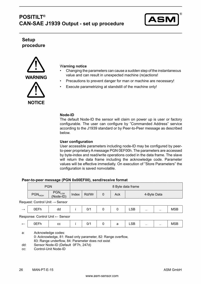
Peer-to-peer message (PGN 0x00EF00), send/receive format
a: Acknowledge codes: 0:Acknowledge,81:Readonlyparameter,82:Rangeoverflow, 83:Rangeunderflow,84:Parameterdoesnotexistdd: SensorNode-ID(Default0F7h,247d)cc: Control-Unit Node-ID
PGN 8Bytedataframe
PGNHIGHPGNLOW
(Node-ID) Index Rd/Wr 0 Ack 4-Byte Data
Request:ControlUnit→Sensor
→ 0EFh dd i 0/1 0 0 LSB .. .. MSB
Response:ControlUnit←Sensor
← 0EFh cc i 0/1 0 a LSB .. .. MSB
26 MAN-PT-E-15 ASM GmbH
www.asm-sensor.com
POSITILT® CAN-SAE J1939 Output - set up procedure
Setup procedure
Warning notice• Changing the parameters can cause a sudden step of the instantaneous
value and can result in unexpected machine (re)actions!• Precautions to prevent danger for man or machine are necessary!• Execute parametrizing at standstill of the machine only!
Node-IDThe default Node-ID the sensor will claim on power up is user or factory configurable. The user can configure by ”CommandedAddress” service according to the J1939 standard or by Peer-to-Peer message as described below.
User configurationUseraccessibleparametersincludingnode-IDmaybeconfiguredbypeer-to-peerproprietaryAmessagePGN0EF00h.Theparametersareaccessedby byte-index and read/write operations coded in the data frame. The slave will return the data frame including the acknowledge code. Parameter valueswillbeeffectiveimmediatly.Onexecutionof”StoreParameters”theconfigurationissavednonvolatile.
WARNING
NOTICE

Example:SetTransmitCycleto10ms,Index31,Node-ID247d(F7h)
PGNHIGH PGNLOW 8Bytedataframe
→ 0EFh F7h 1Fh 01h 00 00 0Ah 00 00 00
← 0EFh cc 1Fh 01h 00 00 0Ah 00 00 00
Example: Read Transmit Cycle value, Index 31
→ 0EFh F7h 1Fh 00 00 00 00 00 00 00
← 0EFh cc 1Fh 00 00 00 0Ah 00 00 00
Example:StoreParameterspermanently,Index28
→ 0EFh F7h 1Ch 01h 00 00 65h 76h 61h 73h
← 0EFh cc 1Ch 01h 00 00 65h 76h 61h 73h
Example: Reload factory defaults, Index 29
→ 0EFh F7h 1Dh 01h 00 00 64h 61h 6Fh 6Ch
← 0EFh cc 1Dh 01h 00 00 64h 61h 6Fh 6Ch
ASM GmbH MAN-PT-E-15 27
www.asm-sensor.com
Configuration examples
POSITILT® CAN-SAE J1939 Output - set up procedure

Parameter Index[dec] Default Range / Selection Unit Read /
WriteControlNode ID 20 247 128...247 rd/wr 1)
Bit rate 21 3(250kB) - rd/wr 1)
Termination resistor 22 00(OFF) 1 (ON)
PTDM27 onlyrd/wr 1)
Store parameters 28 - ”save”2) wrReload factory defaults 29 - ”load”2) wrCommunication
Transmit mode 30 00timer
1 request2 event
rd/wr
Transmit cycle 31 100 10..65535 ms rd/wrPGN Group Extension 32 0 0..255 rd/wrEvent mode hysteresis 38 0 0..16383 steps rd/wr
Process data byte order 39 0 0little/1 big endian rd/wr
Measurement1axis±180°2axes±60° 69 1 0:1axis
80h:2axis rd/wr
Code sequence_X 70 0 0CW1 CCW rd/wr
Code sequence_Y 71 0 0CW1 CCW rd/wr
Resolution(in0.001°) 73 100 10...10000 deg rd/wr Preset 1 axis X/Y 74 0 ±0,1.. deg rd/wrPreset 2 axes X 75 0 ±0,1.. deg rd/wrPreset 2 axes Y 76 0 ±0,1.. deg rd/wr
Averaging Filter (NFilter)
ResponseTime(90%):TR = NFilter*5ms
77 1 1...2553) rd/wr
IdentificationSWVersion 198 - 4 bytes number rdSerial number 199 4 bytes number rdIdentity number 200 - 21 bit number rd
1) Effective on next power-up2)„save“MSB...LSB:73h,61h,76h,65h „load“MSB...LSB:6Ch,6Fh,61h,64h3) average on number of samples
Dependingonconfigurationordereddefaultsettingsmaybedifferent,refertoASMhomepage.
28MAN-PT-E-15 ASM GmbH
www.asm-sensor.com
Configurable parameters
POSITILT® CAN SAE J1939 Output Specification

Process dataProcessdataare transmittedbybroadcastproprietary-B-MessagePGN0x00FFxxwherethe lowbyteisconfigurable.
Datafieldofprocessdata
*)Errorcodes:0=noerror,1=error,internalerror
B7 B6 B5 B4 B3 B2 B1 B0Error Inclination Y Inclination XByte *) MSB LSB MSB LSB
ASM GmbH MAN-PT-E-15 29
www.asm-sensor.com
POSITILT® CAN SAE J1939 Output Specification

30MAN-PT-E-15 ASM GmbH
www.asm-sensor.com
ViewtosensorconnectorSignal wiring / connection
Signal Plug connectionShield 1Excitation+ 2GND 3CAN-H 4CAN-L 5
CAN bus wiring
Connect the device by a T-connector to the CAN trunk line. Total length of stubsshouldbeminimized.Connectterminatingresistors120Ohmatbothends of the trunk line.
POSITILT® CAN SAE J1939 Output Specification
TerminationResistor T-Piece CAN bus cable
Sensor

KAB - XM - M12/4F/W/69K - LITZE
KAB - XM - M12/4F/G/69K - LITZE
KAB - XM - M12/4F/W - LITZEIP69K:
KAB - XM - M12/4F/G - LITZEIP69K:
ASM GmbH MAN-PT-E-15 31
www.asm-sensor.com
KAB - XM - M12/4F/W/69K - LITZE
KAB - XM - M12/4F/G/69K - LITZE
KAB - XM - M12/4F/W - LITZEIP69K:
KAB - XM - M12/4F/G - LITZEIP69K:
Connector cableM12, 4 pinSuitable for 5-pin sensor connectorsshielded*
The 4-lead shielded cable is supplied with a mating4-pin90°M12connectoratoneendand4 wires at the other end. Available lengths are 2m,5mand10m.Wire:crosssectionalarea 0.34mm2.
Order code:
Length in m
Connector cable M12, 4 pinSuitable for 5-pin sensor connectorsshielded*
The 4-lead shielded cable is supplied with a mating 4-pin M12 connector at one end and 4 wires at the other end. Available lengths are 2m,5mand10m.Wire:crosssectionalarea 0.34mm2.
Order code:
Length in m
Signal wiring M12, 4 pin
Connector pin / cable color1 2 3 4brown white blue black
*=Shieldedconnector
POSITILT®
Accessoires

KAB - XM - M12/5F/W/69K - LITZE
KAB - XM - M12/5F/G/69K - LITZE
KAB - XM - M12/5F/W - LITZEIP69K:
KAB - XM - M12/5F/G - LITZEIP69K:
32 MAN-PT-E-15 ASM GmbH
www.asm-sensor.com
KAB - XM - M12/5F/W/69K - LITZE
KAB - XM - M12/5F/G/69K - LITZE
KAB - XM - M12/5F/W - LITZEIP69K:
KAB - XM - M12/5F/G - LITZEIP69K:
Connector cableM12, 5 pinshielded*
The 5-lead shielded cable is supplied with a mating5-pin90°M12connectoratoneendand5 wires at the other end. Available lengths are 2m,5mand10m.Wire:crosssectionalarea 0.34mm2.Order code:
Length in m
Connector cableM12, 5 pinshielded*
The 5-lead shielded cable is supplied with a mating 5-pin M12 connector at one end and 5 wires at the other end. Available lengths are 2 m,5mand10m.Wire:crosssectionalarea 0.34mm2.Order code:
Length in m
Signal wiring M12, 5 pin
Connector pin / cable color1 2 3 4 5brown white blue black grey
*=Shieldedconnector
POSITILT®
Instruction Manual

KAB - XM - M12/5F/G - M12/5M/G - CANKAB - XM - M12/5F/G/69K - M12/5M/G/69K - CAN
KAB - TCONN - M12/5M - 2M12/5F - CAN
KAB - RTERM - M12/5M/G - CAN
IP69K:
ASM GmbH MAN-PT-E-15 33
www.asm-sensor.com
Connector/bus cable M12, 5 pin CAN busshielded*
The 5-lead shielded cable is supplied with a female 5-pin M12 connector at one end and a male 5-pin M12 connector at the other end. Availablelengthsare0.3,2,5and10m.
Order code:
Length in m
Terminating resistance 5 pin M12 CAN bus
T-piece for bus cable M12, 5 pin CAN bus Order code:
Order code:
*=Shieldedconnector
POSITILT®
Instruction Manual

PTAM2/PTDM2
PTAM2/PTDM2 X
Y
PTAM2/PTDM2
PTAM2/PTDM2 X
Y
34 MAN-PT-E-15 ASM GmbH
www.asm-sensor.com
POSITILT® Output characteristics
Output signalOption: Teach-in of home (center) position by PMZ function
Range[°]
0°– θx min +θx max
Radial, 1 axis
Radial, 2 axes
Axial, 1 axis
Axial, 2 axes
Marking
Marking (at the back)
Marking
Marking (at the back)

PTAM27/PTDM27
PTAM27/PTDM27 X
Y
PTAM5/PTDM5
PTAM5/PTDM5 X
Y
ASM GmbH MAN-PT-E-15 35
www.asm-sensor.com
1 axis
2 axes
1 axis
2 axes
Output signalOption: Teach-in of home (center) position by PMZ function
Range[°]
0°– θx min +θx max
POSITILT® Output characteristics

45° / 100%90%
TR [s]
36 MAN-PT-E-15 ASM GmbH
www.asm-sensor.com
POSITILT® Response time
Response time
Response signal
Inclination

ASM GmbH MAN-PT-E-15 37
www.asm-sensor.com
Service Sensors and accessories have to be repaired and adjusted at ASM in Moos inning.
In order to avoid risk of injury and improper handling the customer is notallowed to repair the sensor. No warranty or liability will be granted for ope-ned sensors.
Damaged sensors must be shut down immediately and sent to the factory for repair.
Disposal Disposal according to applicable government regulations.
Calibration The recommended calibration interval is 1 year.
Test protocol is available on request.
POSITILT® Service, calibration, disposal

38MAN-PT-E-15 ASM GmbH
www.asm-sensor.com
POSITILT®
Reliability characteristics
Characteristics Probability of failure 1x10⁻⁶/h
Life period MTTF 110years
Working life 10years
SN29500Failurerateelectroniccomponents(Siemens)Standards
PTAM2/PTDM2, PTAM5/PTDM5, PTAM27/PTDM27
U2 Voltageoutput0.5...10VU6 Voltageoutput0.5...4.5VU8 Voltageoutput0.5...4.5VI1 Currentoutput4...20mA
Reliabilitycharacteristics
Models
Outputs

ASM GmbH MAN-PT-E-15 39
www.asm-sensor.com
Declaration of conformity
The inclination sensor
Manufacturer: ASM GmbH AmBleichbach18-24 85452Moosinning/Germany
Model: PTAM2/PTDM2, PTAM5/PTDM5, PTAM27/PTDM27
complies with the following standards and directives:
Directives: 2004/108/EG(EMC)
Standards: EN61326-1:2013(EMC)
Moosinning, 2nd09.2013
i.A. Peter Wirth Head of Development
POSITILT®
Declaration of conformity

ASM GmbH Automation • Sensorik • MesstechnikAmBleichbach18-24 85452Moosinning/GermanyTelephone:+498123986-0 Telefax:+498123986-500Internet: www.asm-sensor.de www.asmsensors.com E-Mail: [email protected] [email protected]
© byASMGmbH,Moosinning2.0.0/03.2015Subjecttochangewithoutnotice.SeeprotectionnoteDIN34!