AN982: BLUETOOTH® SMART GLUCOSE SENSOR - · PDF file · 2017-07-26practical...
37
AN982: BLUETOOTH® SMART GLUCOSE SENSOR APPLICATION NOTE Thursday, 24 January 2013 Version 1.0
Transcript of AN982: BLUETOOTH® SMART GLUCOSE SENSOR - · PDF file · 2017-07-26practical...

AN982: BLUETOOTH® SMART GLUCOSE SENSOR APPLICATION NOTE
Thursday, 24 January 2013
Version 1.0

Silicon Labs
VERSION HISTORY
Version Comment
1.0 First version
Silicon Labs
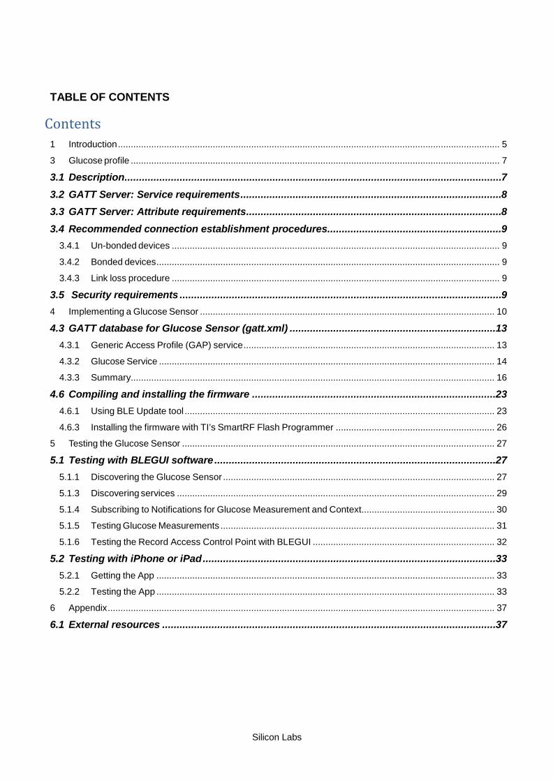
TABLE OF CONTENTS
Contents 1 Introduction ..................................................................................................................................................... 5
3 Glucose profile ................................................................................................................................................ 7
3.1 Description .................................................................................................................................. 7
3.2 GATT Server: Service requirements .......................................................................................... 8
3.3 GATT Server: Attribute requirements ........................................................................................ 8
3.4 Recommended connection establishment procedures ............................................................ 9
3.4.1 Un-bonded devices ................................................................................................................................ 9
3.4.2 Bonded devices ...................................................................................................................................... 9
3.4.3 Link loss procedure ................................................................................................................................ 9
3.5 Security requirements ............................................................................................................... 9
4 Implementing a Glucose Sensor ................................................................................................................... 10
4.3 GATT database for Glucose Sensor (gatt.xml) ....................................................................... 13
4.3.1 Generic Access Profile (GAP) service .................................................................................................. 13
4.3.2 Glucose Service ................................................................................................................................... 14 4.3.3 Summary.............................................................................................................................................. 16
4.6 Compiling and installing the firmware .................................................................................... 23
4.6.1 Using BLE Update tool ......................................................................................................................... 23
4.6.3 Installing the firmware with TI’s SmartRF Flash Programmer .............................................................. 26 5 Testing the Glucose Sensor .......................................................................................................................... 27
5.1 Testing with BLEGUI software ................................................................................................. 27
5.1.1 Discovering the Glucose Sensor .......................................................................................................... 27
5.1.3 Discovering services ............................................................................................................................ 29
5.1.4 Subscribing to Notifications for Glucose Measurement and Context.................................................... 30 5.1.5 Testing Glucose Measurements ........................................................................................................... 31
5.1.6 Testing the Record Access Control Point with BLEGUI ....................................................................... 32
5.2 Testing with iPhone or iPad ..................................................................................................... 33
5.2.1 Getting the App .................................................................................................................................... 33 5.2.2 Testing the App .................................................................................................................................... 33
6 Appendix ....................................................................................................................................................... 37
6.1 External resources ................................................................................................................... 37

Silicon Labs
Page 5 of 38
1 Introduction This application note discusses how to build a Bluetooth 4.0 glucose profile sensor using Bluegiga’s Bluetooth 4.0 software development kit, for use with a DKBLE112 hardware evaluation board and an Apple iPhone or iPad, or other Bluetooth Smart device capable of acting as a glucose collector. The application note contains a practical example of how to build a GATT-based Glucose Profile and how to make a basic glucose sensor device using BGScript scripting language, including authenticated bonding (encryption) and on-module glucose record storage and retrieval.
Various other features of the development kit are also demonstrated in this project for the sake of instruction, such as SPI communication to the on-board LCD, potentiometer ADC readings to simulate glucose levels, and UART debug data output.
Note that the glucose profile as implemented is an official profile standardized by the Bluetooth SIG.

Silicon Labs
Page 6 of 38
2 What is Bluetooth Smart technology? Bluetooth low energy (Bluetooth 4.0) is a new, open standard developed by the Bluetooth SIG. It’s targeted to address the needs of new modern wireless applications such as ultra-low power consumption, fast connection times, reliability and security. Bluetooth low energy consumes 10-20 times less power and is able to transmit data 50 times quicker than classical Bluetooth solutions.
Bluetooth low energy is designed for new emerging applications and markets, but it still embraces the very same benefits we already know from the classical, well established Bluetooth technology:
• Robustness and reliability - The adaptive frequency hopping technology used by Bluetooth low energy allows the device to quickly hop within a wide frequency band, not just to reduce interference but also to identify crowded frequencies and avoid them. On addition to broadcasting Bluetooth low energy also provides a reliable, connection oriented way of transmitting data.
• Security - Data privacy and integrity is always a concern is wireless, mission critical applications. Therefore Bluetooth low energy technology is designed to incorporate high level of security including authentication, authorization, encryption and man-in-the-middle protection.
• Interoperability - Bluetooth low energy technology is an open standard maintained and developed by the Bluetooth SIG. Strong qualification and interoperability testing processes are included in the development of technology so that wireless device manufacturers can enjoy the benefit of many solution providers and consumers can feel confident that equipment will communicate with other devices regardless of manufacturer.
• Global availability - Based on the open, license free 2.4GHz frequency band, Bluetooth low energy technology can be used in world wide applications.
There are two types of Bluetooth 4.0 devices:
• Bluetooth 4.0 single-mode devices that only support Bluetooth low energy and are optimized for low-power, low-cost and small size solutions.
• Bluetooth 4.0 dual-mode devices that support Bluetooth low energy and classical Bluetooth technologies and are interoperable with all the previously Bluetooth specification versions.
Key features of Bluetooth low energy wireless technology include:
• Ultra-low peak, average and idle mode power consumption
• Ability to run for years on standard, coin-cell batteries
• Low cost
• Multi-vendor interoperability
• Enhanced range
Bluetooth low energy is also meant for markets and applications, such as:
• Automotive
• Consumer electronics
• Smart energy
• Entertainment
• Home automation
• Security & proximity
• Sports & fitness

Silicon Labs
Page 7 of 38
3 Glucose profile
3.1 Description
The Glucose Profile enables a device to connect and interact with a glucose sensor for use in consumer and professional healthcare applications. The full Bluetooth SIG specification for the Glucose Profile is available in PDF form here:
https://www.bluetooth.org/docman/handlers/downloaddoc.ashx?doc_id=248025
An organized table structure of the Glucose profile as defined by the Bluetooth SIG is available here:
http://developer.bluetooth.org/gatt/profiles/Pages/ProfileViewer.aspx?u=org.bluetooth.profile.glucose.xml
(Other links present in this document to services and characteristics also go to the Bluetooth SIG service browser online.)
The Glucose Profile defines two roles:
1. Glucose Sensor
The sensor is the devices which has the actual glucose measurement device and provides the GATT structure and data storage for use by a collector (see below). A glucose sensor must include at least a partial implementation of the Device Information service as well as the sensor portion of the Glucose service, as defined by the Bluetooth SIG.
2. Collector
The collector is the device which gathers glucose data from the sensor. In this example, we will do partial testuse an iOS application provided by Nordic Semiconductor for a comprehensive GUI-based collector. This application note does not discuss the implementation of a collector itself.
The figure below shows the relationship of these two roles.
Figure 1: Glucose Profile roles
Generic Access Service Glucose Measurement
Glucose Measurement Context
Glucose Feature
Record Access Control Point
Glucose Service
Device Information Service
Generic Access Service
Device Information Service
Collector Glucose Sensor

Silicon Labs
Page 8 of 38
3.2 GATT Server: Service requirements
The table below describes the service requirements.
Service UUID Glucose Sensor
GAP service 1800 Mandatory
Glucose service 1808 Mandatory
Device Information service 180A Mandatory
Table 1: Service requirements
3.3 GATT Server: Attribute requirements
The table below describes the structure and requirements for the attribute used in the Glucose Service. (Links go to the Bluetooth SIG online characteristic definition browser for that attribute)
Characteristic UUID Length Type Support Security Properties
Glucose Measurement
2A18 Variable
(max 17B)
Hex
Mandatory
None
Notify
Glucose Measurement Context
2A34 Variable
(max 17B)
Hex
Optional
None
Notify
Glucose Feature
2A51
2 bytes
Hex
Mandatory
None
Read
Record Access Control Point
2A52 Variable
(typical 2B)
Hex
Mandatory Writeable with
Authentication
Write, Indicate
Table 2: Glucose Service structure (sensor only)
• Each UUID in this service is an official, adopted 16-bit ID for the characteristic
• The Glucose Measurement and Context length is variable depending on the features supported by the sensor. This demo emulates all specified features (though most data is arbitrarily chosen only for demo purposes). and has a length of 17 bytes. This fits within the maximum payload size for indicated values (20 bytes).
• Security is not necessary to connect to a glucose sensor in order to read a single measurement taken during connection, but it is required to access historical records which may be stored on the device. These records are only accessible through the Record Access Control Point. In order to write control commands to this attribute, the collector must bond (a.k.a. pair) with the sensor. A collector which connects but does not pair will not be allowed to write any values to the control point, and therefore will not be able to access any stored records.
• Glucose Measurement and the optional Glucose Measurement Context cannot be directly read, but may only be pushed (via notifications) from the sensor to the collector, after the collector enables client notifications for those services. Glucose Feature contains a constant value describing the feature set of the sensor device, and may be read as desired by the collector.

Silicon Labs
Page 9 of 38
3.4 Recommended connection establishment procedures
3.4.1 Un-bonded devices
Advertisement duration Parameter Value
First 30 seconds (fast connection) Advertising interval 20ms to 30ms
After 30 seconds (reduced power) Advertising interval 1000ms to 2500ms
Table 3: Advertising parameters for un-bonded Glucose Sensor
• The Glucose Sensor should use the GAP Limited Discoverable Mode with connectable undirected advertising events when establishing an initial connection. (For simplicity, this demo implementation uses GAP General Discoverable Mode.)
• If the connection is not established within a time limit, the sensor may exit GAP Connectable mode. (For simplicity, this demo implementation does not ever exit GAP Connectable mode.)
3.4.2 Bonded devices
The following produce is uses for bonded devices:
• A Glucose Sensor shall enter the GAP Undirected Connectable Mode either when commanded by the user to initiate a connection to a Collector or when a Glucose Sensor has one or more stored records to send to a previously connected Collector.
• The Glucose Sensor should write the address of the target Collector in its White List and set its controller advertising filter policy to ‘process scan and connection requests only from devices in the White List’. The advertisement parameters should be as in Table 3.
• If the connection is not established within a time limit, the sensor may exit GAP Connectable mode.
3.4.3 Link loss procedure
When connection is terminated due to link loss the sensor should attempt reconnection with the Collector by entering the GAP connectable mode using the recommended parameters from Table 3.
3.5 Security requirements
The Glucose Sensor shall bond with the Collector.
When bonding is used:
1. All supported characteristics specified by the Glucose Service shall be set to Security Mode 1 and either Security Level 2 or 3.
2. The Glucose Sensor shall use the SM Slave Security Request procedure to inform the Collector of its security requirements.
3. All characteristics specified by the Device Information Service that are relevant to this profile should be set to the same security mode and level as the characteristics in the Glucose Service.

Silicon Labs
Page 10 of 38
4 Implementing a Glucose Sensor The chapter contains step by step instructions how to implement a stand-alone Glucose Sensor with Bluegiga’s Bluetooth 4.0 Software Development Kit. The chapter is split into following steps:
1. Creating a project
2. Defining hardware configuration
3. Building Glucose and Device Information Services with Profile Toolkit
4. Writing BGScript source code
5. Compiling the GATT database and BGScript into binary firmware
6. Installing the firmware into BLE112 or DKBLE112 hardware
The actual project comes as an example with the Bluegiga’s Bluetooth low energy Software Development Kit v.1.1.1 or newer under the \example\glucose_sensor\ directory.

Silicon Labs
Page 11 of 38
4.1 Creating a project (project.xml) The Glucose Sensor implementation is started by first creating a project file (project.xml), which defines the resources use by the project and the firmware output file. This project file includes a description of each of the main elements of the project.
Figure 2: Project file (project.xml)
• <gatt> Defines the XML file containing the GATT database.
• <hardware> Defines the XML file containing the hardware configuration.
• <script> Defines the BGScript file which contains the BGScript code.
• <config> Defines the application configuration file.
• <image> Defines the output HEX file containing the firmware image.
<?xml version="1.0" encoding="UTF-8" ?> <project>
<gatt in="gatt.xml" /> <hardware in="hardware.xml" /> <script in="glucose_demo.bgs" /> <config in="config.xml" /> <image out="out.hex" />
</project>
Silicon Labs
Page 12 of 38
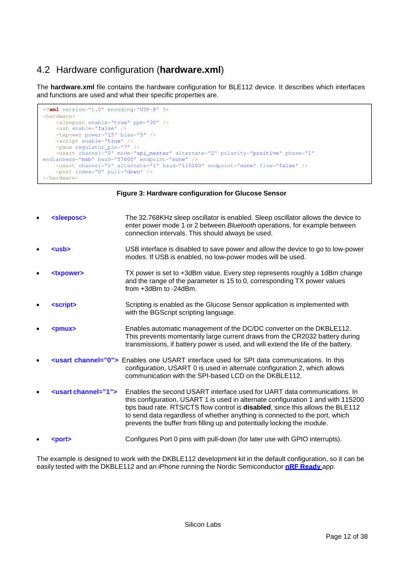
4.2 Hardware configuration (hardware.xml) The hardware.xml file contains the hardware configuration for BLE112 device. It describes which interfaces and functions are used and what their specific properties are.
Figure 3: Hardware configuration for Glucose Sensor
• <sleeposc> The 32.768KHz sleep oscillator is enabled. Sleep oscillator allows the device to
enter power mode 1 or 2 between Bluetooth operations, for example between connection intervals. This should always be used.
• <usb> USB interface is disabled to save power and allow the device to go to low-power
modes. If USB is enabled, no low-power modes will be used. • <txpower> TX power is set to +3dBm value. Every step represents roughly a 1dBm change
and the range of the parameter is 15 to 0, corresponding TX power values from +3dBm to -24dBm.
• <script> Scripting is enabled as the Glucose Sensor application is implemented with
with the BGScript scripting language. • <pmux> Enables automatic management of the DC/DC converter on the DKBLE112.
This prevents momentarily large current draws from the CR2032 battery during transmissions, if battery power is used, and will extend the life of the battery.
• <usart channel=”0”> Enables one USART interface used for SPI data communications. In this
configuration, USART 0 is used in alternate configuration 2, which allows communication with the SPI-based LCD on the DKBLE112.
• <usart channel=”1”> Enables the second USART interface used for UART data communications. In
this configuration, USART 1 is used in alternate configuration 1 and with 115200 bps baud rate. RTS/CTS flow control is disabled, since this allows the BLE112 to send data regardless of whether anything is connected to the port, which prevents the buffer from filling up and potentially locking the module.
• <port> Configures Port 0 pins with pull-down (for later use with GPIO interrupts).
The example is designed to work with the DKBLE112 development kit in the default configuration, so it can be easily tested with the DKBLE112 and an iPhone running the Nordic Semiconductor nRF Ready app.
<?xml version="1.0" encoding="UTF-8" ?> <hardware>
<sleeposc enable="true" ppm="30" /> <usb enable="false" /> <txpower power="15" bias="5" /> <script enable="true" /> <pmux regulator_pin="7" /> <usart channel="0" mode="spi_master" alternate="2" polarity="positive" phase="1"
endianness="msb" baud="57600" endpoint="none" /> <usart channel="1" alternate="1" baud="115200" endpoint="none" flow="false" /> <port index="0" pull="down" />
</hardware>
Silicon Labs
Page 13 of 38
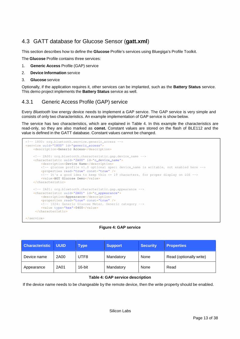
4.3 GATT database for Glucose Sensor (gatt.xml) This section describes how to define the Glucose Profile’s services using Bluegiga’s Profile Toolkit.
The Glucose Profile contains three services:
1. Generic Access Profile (GAP) service
2. Device Information service
3. Glucose service
Optionally, if the application requires it, other services can be implanted, such as the Battery Status service. This demo project implements the Battery Status service as well.
4.3.1 Generic Access Profile (GAP) service
Every Bluetooth low energy device needs to implement a GAP service. The GAP service is very simple and consists of only two characteristics. An example implementation of GAP service is show below.
The service has two characteristics, which are explained in Table 4. In this example the characteristics are read-only, so they are also marked as const. Constant values are stored on the flash of BLE112 and the value is defined in the GATT database. Constant values cannot be changed.
Figure 4: GAP service
Characteristic UUID Type Support Security Properties
Device name 2A00 UTF8 Mandatory None Read (optionally write)
Appearance 2A01 16-bit Mandatory None Read
Table 4: GAP service description
If the device name needs to be changeable by the remote device, then the write property should be enabled.
<!-- 1800: org.bluetooth.service.generic_access --> <service uuid="1800" id="generic_access">
<description>Generic Access</description>
<!-- 2A00: org.bluetooth.characteristic.gap.device_name --> <characteristic uuid="2A00" id="c_device_name">
<description>Device Name</description> <!-- glucose profile v1.0 optional spec: device_name is writable, not enabled here --> <properties read="true" const="true" /> <!-- It's a good idea to keep this <= 19 characters, for proper display on iOS --> <value>BGT Glucose Demo</value>
</characteristic>
<!-- 2A01: org.bluetooth.characteristic.gap.appearance --> <characteristic uuid="2A01" id="c_appearance">
<description>Appearance</description> <properties read="true" const="true" /> <!-- 1024: Generic Glucose Meter, Generic category --> <value type="hex">0400</value>
</characteristic> </service>

Silicon Labs
Page 14 of 38
4.3.2 Glucose Service
The sensor is the device implementing the GATT Server, so it must also implement the Glucose service.
The Glucose service is defined as below:
Characteristic UUID Length Type Support Security Properties
Glucose Measurement
2A18 Variable
(max 17B)
Hex
Mandatory
None
Notify
Glucose Measurement Context
2A34 Variable
(max 17B)
Hex
Optional
None
Notify
Glucose Feature
2A51
2 bytes
Hex
Mandatory
None
Read
Record Access Control Point
2A52 Variable
(typical 2B)
Hex
Mandatory Writeable with
Authentication
Write, Indicate
Table 5: Glucose Service description
The Glucose Service is created by adding the code below to the gatt.xml file:
Figure 5: Glucose Service (sensor only)
The Glucose service is explained below:
• First, the advertise=”true” option is needed for the for the <service> tag. When the sensor advertises, the UUID of the glucose service (0x1808) is included in the data field of the advertisement packets, so the device can be easily identified by the demote devices. Many devices (including iPhones/iPads) often filter scans based on UUID, so if this is not included in the advertisement packet, your device will not be seen by the collector.
• Each attribute is given an id field (e.g. “c_glucose_measurement”), which is used in the included BGScript code for a named reference to the numeric attribute handle. Numeric handles are assigned
<!-- 1808: org.bluetooth.service.glucose --> <service uuid="1808" advertise="true">
<description>Glucose Service</description> <characteristic uuid="2A18" id="c_glucose_measurement">
<description>Glucose Measurement</description> <properties notify="true" /> <value length="17" variable="true" />
</characteristic> <characteristic uuid="2A34" id="c_glucose_measurement_context">
<description>Glucose Measurement Context</description> <properties notify="true" /> <value length="17" variable="true" />
</characteristic> <characteristic uuid="2A51" id="c_glucose_feature">
<description>Glucose Feature</description> <properties read="true" const="true" /> <value length="2" type="hex">07FF</value>
</characteristic> <characteristic uuid="2A52" id="c_record_access_control_point">
<description>Record Access Control Point</description> <properties indicate="true" write="true" authenticated_write="true" /> <value length="17" variable="true" />
</characteristic> </service>

Silicon Labs
Page 15 of 38
during the compile process based on the structure of the GATT database, so it is helpful to use named references instead so that you do not need to know the handles beforehand. There is no official naming convention requirement for these IDs. The only requirement is that they must be alphanumeric (letters, numbers, and underscore characters only), and they must not overlap with any BGScript keywords.
• Read, write, and notify properties are enabled on the various attributes as required by the service specification. Using notify means that the collector will be able to “subscribe” (enable notifications) to this attribute, and then any value updates done by the sensor will be automatically pushed out to the collector. Indications and notifications are the same except that indications are acknowledged by the remote end, while notifications are not (similar to the difference between TCP and UDP within the IP network protocol). Note that on the “c_record_access_control_point” attribute, both write and authenticated_write are present. This is required; you cannot use simply authenticated_write without also enabling write.

Silicon Labs
Page 16 of 38
4.3.3 Summary
The full GATT database implementation is shown below. The source code in the demo project has additional comments which explain the specification requirements and actual values used in much more detail.
Figure 6: Glucose Sensor Profile GATT database
<?xml version="1.0" encoding="UTF-8" ?> <configuration>
<service uuid="1800" id="generic_access"> <description>Generic Access</description> <characteristic uuid="2A00" id="c_device_name">
<description>Device Name</description> <properties read="true" const="true" /> <value>BGT Glucose Demo</value>
</characteristic> <characteristic uuid="2A01" id="c_appearance">
<description>Appearance</description> <properties read="true" const="true" /> <value type="hex">0400</value>
</characteristic> </service> <service uuid="180A" id="device_information">
<description>Device Information</description> <characteristic uuid="2A29" id="c_manufacturer_name">
<description>Manufacturer Name</description> <properties read="true" const="true" /> <value>Bluegiga</value>
</characteristic> <characteristic uuid="2A24" id="c_model_number">
<description>Model Number</description> <properties read="true" const="true" /> <value>BG-BLE-GLUCOSE</value>
</characteristic> <characteristic uuid="2A25" id="c_serial_number">
<description>Serial Number</description> <properties read="true" const="true" /> <value>123456789</value>
</characteristic> <characteristic uuid="2A27" id="c_hardware_revision_string">
<description>Hardware Revision String</description> <properties read="true" const="true" /> <value>H1.0.0</value>
</characteristic> <characteristic uuid="2A26" id="c_firmware_revision_string">
<description>Firmware Revision String</description> <properties read="true" const="true" /> <value>F1.0.0</value>
</characteristic> <characteristic uuid="2A28" id="c_software_revision_string">
<description>Software Revision String</description> <properties read="true" const="true" /> <value>S1.0.0</value>
</characteristic> <characteristic uuid="2A23" id="c_system_id">
<description>System ID</description> <properties read="true" const="true" /> <value type="hex">112233FFFE778899</value>
</characteristic> </service> <service uuid="1808" advertise="true">
<description>Glucose Service</description> <characteristic uuid="2A18" id="c_glucose_measurement">
<description>Glucose Measurement</description> <properties notify="true" /> <value length="17" variable="true" />
</characteristic> <characteristic uuid="2A34" id="c_glucose_measurement_context">
<description>Glucose Measurement Context</description> <properties notify="true" /> <value length="17" variable="true" />
</characteristic> <characteristic uuid="2A51" id="c_glucose_feature">
<description>Glucose Feature</description> <properties read="true" const="true" /> <value length="2" type="hex">07FF</value>
</characteristic> <characteristic uuid="2A52" id="c_record_access_control_point">
<description>Record Access Control Point</description> <properties indicate="true" write="true" authenticated_write="true" /> <value length="17" variable="true" />
</characteristic> </service> <service uuid="180F" id="battery_service">
<description>Battery Service</description> <characteristic uuid="2A19" id="c_battery_level">
<description>Battery Level</description> <properties read="true" notify="true" /> <value length="1" type="hex" />
</characteristic> </service>
</configuration>

Silicon Labs
Page 17 of 38
4.4 Application Configuration (config.xml) The config.xml file contains the application configuration for BLE112 device. This file is not mandatory for your project since all of the default values are typically acceptable, but it is useful for specific requirements such as script timeout control (as below) or UART optimization settings.
Figure 7: Application configuration for Glucose Sensor
• <script_timeout> Disables script timeout. This generally not advisable without a specific reason,
but in this implementation, accessing the stored records through the Record Access Control Point attribute can take more than the default number of allowed script operations to complete, especially if there are a large number of stored records. This is therefore used to ensure that all stored records may be retrieved without issue. The default value (1000) is enough for only about 10 records.
The other settings available in config.xml are not necessary for this demo.
<?xml version="1.0" encoding="UTF-8" ?> <config>
<script_timeout value="0" /> </config>
Silicon Labs
Page 18 of 38
4.5 BGScript for Glucose Sensor (glucose_sensor.bgs)
The example implements a standalone glucose sensor device where no external host processor is needed. The Glucose sensor application is created as a BGScript script application and the BGScript code is explained in this chapter.
BGScript uses an event-based programming approach. The script is executed when an event takes place, and the programmer may register listeners for various events.
The glucose sensor BGScript application uses the following event listeners:
4.5.1 System: Boot event (system_boot)
When the system is started or reset, a system_boot event is generated. This event listener should be the entry point for all the BGScript applications, and provides a perfect opportunity for initializing any required variables.
In the glucose sensor demo, the following tasks take place in the system_boot event handler:
• Initialize status tracking variables and tick counter • Set up GPIO interrupts for catching button presses • Enable bonding • Begin advertising • Start a 1-second continuous timer • Load information from public store (PS) keys concerning stored records • Initialize battery level characteristic to 95% (testing value) • Output debug boot data to UART • Initialize DKBLE112 LCD and display status
The actual project source code contains this code along with many detailed comments.
4.5.2 Bluetooth: Connection event (connection_status)
When the Bluetooth connection is established a connection event occurs. For this purpose, an event listener is added to the BGScript code which tracks the connection status, sends debug data out the UART port, and updates the LCD appropriately.
Note: because bonding is used, when a collector bonds with the sensor, a second connection_status event will be fired when the connection becomes ecrypted. If/when this occurs using this demo, the LCD will be updated again to show “Encrypted” instead of simply “Connected”. Remember that you will not be able to access stored records using the Record Access Control Point if the connection is not encrypted.
4.5.3 Bluetooth: Disconnection event (connection_disconnected).
If the Bluetooth connection is a lost, a disconnection event occurs. For this purpose, an event listener is added to the BGScript and it does almost the same as the boot event listener; it sets the application state and restarts the advertisement procedure.
Note: a Bluetooth Smart device will not automatically resume advertising when a connection is lost. It will be put into an idle state. If you want the device to resume advertising (typically desirable), you must explicitly do this.

Silicon Labs
Page 19 of 38
4.5.4 Data: Receiving control data from the remote device (attributes_value)
The ATTribute protocol is used to transmit data over a Bluetooth connection. A remote device can use an ATT write operation to write up to 20 bytes of data. With the glucose sensor demo, only one attribute is writable, the “Record Access Control Point.” Therefore, in this project, the attributes_value event will only occur then if the connection is encrypted (since authenticated write is required for this attribute).
The BGSciprt code checks to make sure the attribute handle matches the c_record_access_control_point value first (not technically necessary in this case since only one attribute is writable, but very good practice), and then parses the value written. This attribute is used for sending commands such as “Report stored records” or “Delete stored records.” The glucose profile describes many possible commands, but for this demo, only the “Report stored records” command is implemented (opcode value = 0x01).
According to the profile specification, the first byte of the value written to the attribute is the opcode value, and the second byte is the operator. When the “Report stored records” opcode is used, the operator byte controls which records should be reported. For this deom, only the “All records” (operator = 0x01), “First record” (operator = 0x05), and “Last record” (operator = 0x06) are implemented, since these are the only operations implemented in the nRF demo iOS app.
In this project, records are stored in a ring buffer implemented using the PS key storage space provided right on the BLE112 module itself. There are 128 key slots available, each holding up to 32 bytes. The first key is available at address 0x8000, and the last one at 0x807F. The last slot (0x807F) is used for storing the configuration data and stored record count, leaving 127 more slots. The first record is stored in 0x8000, the second in 0x8001, and so on. When 0x807E is reached, the next record will be stored on 0x8000. The ring buffer is maintained using a “head” index variable and a “record count” variable.
Each glucose reading generates a 17-byte measurement value and a corresponding 16-byte measurement context value. This is a total of 33 bytes, which is too big to fit in a single 32-byte PS key. Therefore, the final two bytes of the measurement value (which is the “status” subfield of the value) are not stored. In an ideal implementation, this would not be necessary.
The First/Last/All buttons in the nRF demo app each write a value to this attribute, and the resulting operation is done inside the attributes_write event handler. This involves reading the requested record(s) from the PS key storage area, then writing the measurement and measurement context values to the local GATT attributes, which subsequently pushes them to the connected client using notifications.
For detail on exactly how this is done, refer to the project source code and comments.
4.5.5 IO: Detecting button presses (hardware_io_port_status)
For controlling the behavior of the sensor, this project makes use of two buttons on the DKBLE112 board.
• P0_0 is used to trigger a new glucose reading (using the ADC value read through the potentiometer also on the DKBLE112).
• P0_1 is used to reset all stored records and bonding information, if present.
Pressing the buttons on the DKBLE112 momentarily brings those lines to a logic HIGH state. These signals are configured to generate interrupts by the following line back in the system_boot event handler:
call hardware_io_port_config_irq(0, 3, 0)
The first parameter specifies the port, the second is the bitmask for which pins to enable interrupts on, and the third is the rising or falling edge setting. Interrupts can currently only be enabled on Port 0 and Port 1. The parameters used in the command above are as follows:
0 = Port 0
3 = 0b00000011, bits 0 and 1 are set, so interrupts enables on Pin 0 and Pin 1 of Port 0
0 = Rising edge
Remember that in hardware.xml, we also configured Port 0 to be pulled down, so that the rising edge will be more reliably detected. The I/O signals are not de-bounced in this demo.

Silicon Labs
Page 20 of 38
The P0_0 button press initiates an ADC read, which triggered immediately but takes a few milliseconds to complete. Therefore, the ADC read generates another event (hardware_adc_result) which we also catch. Although we only use one simultaneous or consecutive ADC read operation in this project, note that multiple ADC reads must be cascaded such that the second is not triggered until the first completes.
The P0_1 button press manually clears all bonding entry storage slots, sets the stored record count to zero, and moves the record storage ring buffer head index back to the beginning. It does not actually erase the PS key values, since this is not necessary.
4.5.6 Timer: 1-second clock tick (hardware_soft_timer)
For basic 1-second “tick” tracking, we enabled the soft timer back in the system_boot event handler with the following line:
call hardware_set_soft_timer(32768, 0, 0)
The first parameter specifies the interval relative to the main oscillator, which is 32768 Hz. The timer ticks every (value / 32768) seconds, which in this case is exactly 1 second. The accuracy of this timer is +/- 30ppm, so it is suitable for basic tick tracking of this kind.
The second parameter is the assigned timer handle (should always be “0” in the v1.1 SDK), and the third is whether it is repeating (0) or single shot (1). We want it to fire every second, so it is configured to be repeating.
Inside the timer event handler, we mainly do simple animation on the SPI LCD on the DKBLE112 to indicate activity or revert temporary status messages back to the default “Advertising” or “Connected” or “Encrypted” message. While advertising, a single “?” character will blink on and off once per second. While connected (or encrypted), it will alternate between the “+” and “*” characters.
This event handler also triggers a battery level ADC reading, which is used to update the c_battery_status attribute value when obtained later in the hardware_adc_result handler. The internal battery level ADC channel is 15.
4.5.7 ADC Result: Battery and Glucose measurement (hardware_adc_result)
This event is triggered when the previously requested ADC read operation completes. We handle two specific cases in this demo: the battery value, and the potentiometer value used to emulate a glucose concentration reading. A real glucose sensor would use actual hardware capable of detecting the glucose concentration in a blood sample. Since this hardware is not available on our dev kit, we use the potentiometer connected to P0_6 instead.
The battery level is computed from the ADC read range (0-32768) and scaled to the required 0-100 level, where 0% = 2.0v and 100% = 2.52v (determined empirically with a fresh CR2032). This single byte is written to the c_battery_level attribute, which is then notified to or read by the collector as desired.
The glucose measurement and context values are more complex, but built one byte at a time in great detail in the BGScript code according to the glucose service definition. The particular structure of these two values depends on which features are implemented on the glucose sensor itself. For this demo, we emulate all available features that are described by the specification.

Silicon Labs
Page 21 of 38
The 17-byte Glucose Measurement attribute is built with the following data:
Byte(s)
Field Name
Data Type
Demo Value
Notes
0
Flags
8-bit hex
0x1B
Time Offset field enabled Glucose Concentration units are kg/L Type field enabled Sample location field enabled Sensor Status field enabled Context Information enabled
(sent via Glucose Measurement Context attribute)
1:2
Sequence Number
16-bit hex
Variable
Starts at 0, increments for each new reading
3:9
Base Time
7-byte hex
Variable 3:4=year, 5=month, 6=day, 7=hour, 8=minute, 9=second 0xYYYYMMDDHHmmss
10:11
Time Offset
16-bit hex
Variable
Seconds to offset from Base Time value
12:13 Glucose Concentration
(kg/L) 16-bit SFLOAT
Variable
Depends on DKBLE112 potentiometer setting
14 [7-4]
Type field
4-bit hex
0x1
0x1 = Capillary Whole Blood
14 [3-0]
Sample Location
4-bit hex
0x1
0x1 = Finger
15:16
Sensor Status
16-bit hex
0x0000
0 indicates no error
Table 6: Glucose Measurement Structure
The 17-byte Glucose Measurement Context attribute is built with the following data:
Byte(s)
Field Name
Data Type
Demo Value
Notes
0
Flags
8-bit hex
0x5F
Carbohydrate ID enabled Carbohydrate units are kg Meal enabled Tester enabled Health enabled Exercise Duration enabled Exercise Intensity enabled Medication ID enabled Medication units are kg HbA1C precise percentage enabled
1:2
Sequence Number
16-bit hex
Variable
Must match corresponding measurement
3
Carbohydrate ID
8-bit hex
0x03
0x03 = Dinner
4:5
Carbohydrate (kg)
16-bit SFLOAT
0x13E1 0xE113 = 2.75 kg in SFLOAT format
(0b1110 0001 0001 0011, little endian)

Silicon Labs
Page 22 of 38
6 Meal
8-bit hex
0x02
0x02 = Postprandial
7 [7:4]
Tester
4-bit hex
0x2
0x2 = Health Care Professional
7 [3:0]
Health
4-bit hex
0x4
0x4 = Under Stress
8:9
Exercise Duration
16-bit hex
0x1E00
0x001E = 30 seconds (little-endian)
10
Exercise Intensity
8-bit hex
0x64
0x64 = 100% (range = 0-100)
11
Medication ID
8-bit hex
0x02
0x02 = Short acting insulin
12:13
Medication (kg)
16-bit SFLOAT
0x05E0 0xE005 = 0.05 kg in SFLOAT format
(0b1110 0000 0000 0101, little-endian)
14:15
HbA1c (%)
16-bit SFLOAT
0x1DE2 0xE21D = 5.41% in SFLOAT format
(0b1110 0010 0001 1101, little-endian)
Table 7: Glucose Measurement Context Structure
These two attributes are built field-by-field in the hardware_adc_result event handler. All of the field values in both attributes are static (which they would not be in a real glucose sensor), with the exception of the sequence number, glucose concentration value, and time offset. The time offset field value is set to whatever the sequence number is, which gives the effect that each glucose measurement appears to be take one second after the previous one.
For a detailed look at how this code actually works, refer to the “glucose_sensor.bgs” BGScript source file.

Silicon Labs
Page 23 of 38
4.6 Compiling and installing the firmware
4.6.1 Using BLE Update tool
When you want to test your project, you need to compile the hardware settings, application configuration, GATT database, and BGScript code into a binary firmware file. The easiest way to do this is with the BLE Update tool, which both compiles and flashes the firmware onto a BLE112 module using a CC debugger.
In order to compile and install the project:
1. Connect CC debugger to the PC via USB
2. Connect the CC debugger to the debug interface on the BLE112
3. Press the button on CC debugger and make sure the LED turns green
4. Start the BLE Update tool
5. Make sure the CC debugger is shown in the Port drop down list
6. Use Browse to locate your project.xml file
7. Press Update
BLE Update tool will compile the project and install it into the target device.
Figure 7: Compile and install with BLE Update tool

Silicon Labs
Page 24 of 38
The View Build Log opens up a dialog that shows the bgbuild compilere output and the RAM and Flash memory allocations.
Figure 8: BLE Update build log

Silicon Labs
Page 25 of 38
4.6.2 Compiling using bgbuild.exe
The project can also be compiled with the bgbuild.exe command line compiler. The BGBuild compiler simply generates the firmware image file, which can be installed afterwards to the BLE112.
In order to compile the project using BGBuild:
1. Open Windows Command Prompt (cmd.exe)
2. Navigate to the directory where your project is
3. Execute BGbuild.exe compiler
Syntax: bgbuild.exe <project file>
Figure 9: Compiling with BGBuild.exe
If the compilation is successful, a .hex file is generated, which can be installed into a BLE112 module.
On the other hand, if the compilation fails due to syntax errors in the BGScript or GATT files, the BGBuild utility will display an error message.

Silicon Labs
Page 26 of 38
4.6.3 Installing the firmware with TI’s SmartRF Flash Programmer
The Texas Instruments SmartRF Flash Programmer can also be used to install the firmware into the target device using the CC debugger.
In order to install the firmware with TI flash tool:
1. Connect CC debugger to the PC via USB
2. Connect the CC debugger to the debug interface on the BLE112
3. Press the button on CC debugger and make sure the LED turns green
4. Start the TI flash Programmer tool
5. Select program CCxxxx SoC or MSP430
6. Make sure the target device is recognized and displayed in the System-on-Chip field
7. Make sure the “Retain IEEE address when programming the chip” field is checked
8. Select the .hex file you want to program to the target device
9. Select Erase, Program and Verify
10. Finally press Perform actions and make sure the installation is successful
Figure 10: TI’s flash programmer tool
Note:
TI Flash tool should NOT be used with the Bluegiga Bluetooth Smart SDK v.1.1 or newer, but BLE Update tool should be used instead. The BLE112 and BLED112 devices contain a security key which is needed for the firmware to operate, and if the device is programmed with TI flash tool, this security key will be erased.

Silicon Labs
Page 27 of 38
5 Testing the Glucose Sensor
5.1 Testing with BLEGUI software
This section describes how to test the Glucose Sensor application with BLEGUI software. 5.1.1 Discovering the Glucose Sensor
As soon as the Glucose Sensor is powered on, it starts to advertise itself. At this point, a BLED112 USB dongle can be used to detect the glucose sensor using the BLEGUI software.
Preparations:
1. Connect BLED112 USB dongle to a PC
2. Start BLEGUI software
3. Select the correct COM port from the drop down menu and press Attach
4. Execute the Command – Info command to make sure the communication works
Discovering the Glucose Sensor:
1. Set desired scan parameters, check Active Scanning box and press Set Scan Parameters button
2. Select Generic scanning mode and Start scanning
3. If the glucose sensor is powered on, in range, and not connected, it should appear in the main view.
Figure 11: Scanning for the Glucose Sensor

Silicon Labs
Page 28 of 38
5.1.2 Establishing a Bluetooth connection
1. Press the Connect button located next to the device you want to connect to.
a. If the connection is successful, the connect button will change to Disconnect.
b. If the connection fails, an error message will appear in the Log view.
Figure 12: Connected to Glucose Sensor
2. Open the Tools Security Manager dialog and check the “Bondable” option.
Figure 13: Glucose Profile roles
3. Click the “Set Parameters” button in the dialog to enable bonding, then close the dialog.
4. Press the Encrypt button located between the Disconnect button and GATT button. This will bond the BLED112 with the BLE112 running the glucose sensor project.
a. If encryption is successful, you will see the following entry appear in the Log view: 2013.01.19 22:08:49.0912 ble_rsp_sm_encrypt_start handle: 0 result: 0 ['No Error']
b. If the connection fails, an error message will appear in the Log view.

Silicon Labs
Page 29 of 38
5.1.3 Discovering services
Once you’ve connected to a device, you can use the ATTribute protocol to discover what services it supports. To discover the services of the glucose sensor:
1. Press the GATT button of the device you’ve just connected in order to start the GATT tool.
2. Press Service Discover button to start a GATT primary service discovery procedure.
Figure 14: GATT service discovery
The four services defined in the gatt.xml should be visible in the GATT tool.

Silicon Labs
Page 30 of 38
5.1.4 Subscribing to Notifications for Glucose Measurement and Context
The Glucose Measurement and Glucose Measurement Context attributes cannot be read directly, but only push new data out via notifications. Notifications are not enabled by default, and must be enabled explicitly. Notification settings (and indication settings) are set per-client, and will only persist between disconnections if a client has been bonded. Otherwise they must be re-enabled after disconnecting.
In order to enable the notifications:
1. Select the Glucose Service (UUID 1808) in the BLEGUI’s GATT view
2. Press Descriptors Discover in order to see all characteristics and descriptors in the glucose service
3. Once the descriptors discovery is complete, select the Client Characteristic Configuration (UUID: 2902) value that relates to the Glucose Measurement (UUID: 2A18) and select it
4. In order to enable notifications for the Glucose Measurement, enter a “1” in the text box below the GATT table, then click Write to write the value to the Client Characteristics Configuration.
5. Finally, make sure the write operation is executed properly (see Log)
6. Repeat steps 3 & 4 for the Glucose Measurement Context (UUID: 2A34) Client Characteristic Configuration (UUID 2902) to enable notifications for that attribute as well.
Figure 15: Enabling notifications

Silicon Labs
Page 31 of 38
5.1.5 Testing Glucose Measurements
Now that we have connected, bonded, and enabled notifications, we can test to make sure the measurements are being taken and sent correctly.
In order to test measurements:
1. Press the P0_0 button on the DKBLE112 (or, if not using the DK, momentarily bring P0_0 HIGH).
2. You should see two new values come in below in the Log view, and:
o One new value will appear in the “Raw” column of the 2A18 attribute (measurement). Example: 1b0400d9070718101e00040014a7110000
o One new value will appear in the “Raw” column of the 2A34 attribute (context). Example: 5f04000313e10224001e640205e01de200
3. Verify from Log view that no error is received.
Figure 16: Receiving glucose measurements and context updates

Silicon Labs
Page 32 of 38
5.1.6 Testing the Record Access Control Point with BLEGUI
The Record Access Control Point is used to access any stored measurements on the glucose sensor. After pressing the P0_0 button a few times to take sample measurements, you can send a “Retrieve All Records” command to test the record access method. It is difficult to see multiple records come in within the BLEGUI interface since they are repeatedly notified into the same attribute sequentially, but you can verify in the log that you receive multiple records.
In order to test record access:
1. Select the Record Access Control Point (UUID 2A52) attribute.
2. Type “0101” in the text box below the GATT table, then click the Write button.
3. You should see a set of notified values appear in the Log window.
4. If you see an error in the Log, verify that your “Bondable” setting is correct within the Tools Security Manager dialog, and verify that connection is in fact encrypted by clicking the “Encrypt” button again.
You can test “Retrieve First Record” by using “0105” in step 2, or “Retrieve Last Record” by using “0106”.
Silicon Labs
Page 33 of 38
5.2 Testing with iPhone or iPad
There is an app created by Nordic Semiconductor for Bluetooth Smart enabled iOS devices (iPhone 4S/5, iPad 3/4/Mini), which can be used to test the glucose sensor.
This section briefly describes how to test the glucose sensor BGScript project using an iPhone. 5.2.1 Getting the App
You can find the app in iTunes here: https://itunes.apple.com/us/app/nrfready- utility/id497679111
Alternatively, you can open the App Store on your iPhone and search for “nrfready” to find the app. Note that while the app will run perfectly well on an iPad, you may need to specifically search for iPhone apps, because it isn’t currently built as a universal app.
5.2.2 Testing the App
Once you’ve installed the App to your iPhone or iPad, the following steps are required:
1. Power on the glucose sensor (for example DKBLE112)
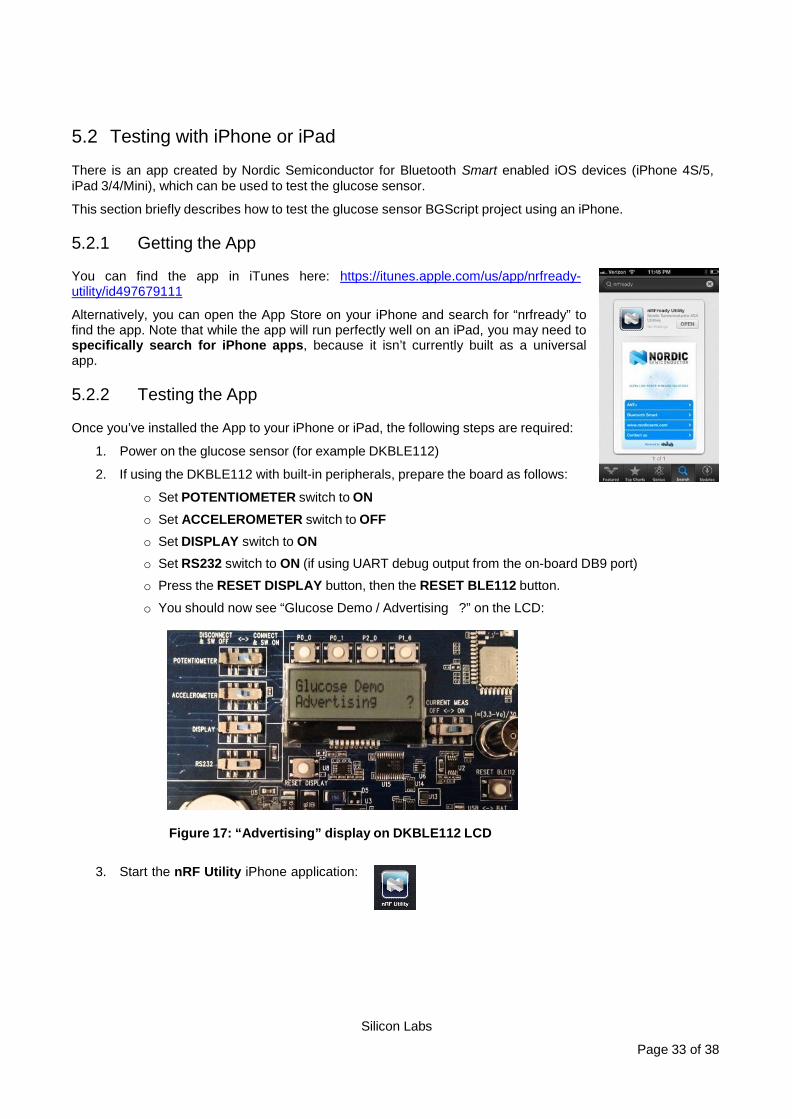
2. If using the DKBLE112 with built-in peripherals, prepare the board as follows:
o Set POTENTIOMETER switch to ON
o Set ACCELEROMETER switch to OFF o Set DISPLAY switch to ON o Set RS232 switch to ON (if using UART debug output from the on-board DB9 port) o Press the RESET DISPLAY button, then the RESET BLE112 button.
o You should now see “Glucose Demo / Advertising ?” on the LCD:
Figure 17: “Advertising” display on DKBLE112 LCD
3. Start the nRF Utility iPhone application:

Silicon Labs
Page 34 of 38
4. Dismiss the disclaimer that appears.
5. Select the “Bluetooth Smart” item from the main welcome screen.
6. Tap the “BGM” icon from the list of services to enter the Blood Glucose Monitor screen.
Figure 18: nRF Application Startup
7. Tap the gray “gear” icon near the top right corner to enter the Settings screen.
8. Slide the “Wildcard” option to ON.
9. Tap the gray “back arrow” icon near the top left, then click the “CONNECT” button.
Figure 19: nRF Application Connection

Silicon Labs
Page 35 of 38
10. You should now be connected, but not yet bonded with the BLE112. If you are using the DKBLE112, the LCD should show the following:
Figure 20: “Connected” display on DKBLE112 LCD
11. If you have not already bonded with the BLE112 running the glucose sensor demo, you should see a Bluetooth Pairing Request confirmation appear. Click the “Pair” button to bond. The DKBLE112 (if present) will now show “Encrypted”, like this:
Figure 21: App Bonding “Encrypted” display on DKBLE112 LCD
Note: if the pairing request does not appear at this point, you may need to do one or more of the following operations:
o Go to the Bluetooth area of the Settings app on your iPhone and “Forget” the BGT Glucose Demo device, if present.
o Turn Bluetooth off and then back on again on your iPhone. o Completely power-cycle your iPhone (not usually required). o Click the P0_1 button on the DKBLE112 board to reset all settings and erase bonding entries.
o Reflash the glucose sensor project onto your BLE112 (also clears bonding entries). 12. Press the P0_0 button on the DKBLE112 to trigger a glucose reading. The app should show a new
record every time you press the button. You can affect the glucose concentration value by changing the potentiometer. For a thorough test, make sure you trigger at least a few records.

Silicon Labs
Page 36 of 38
13. Tap the “First” button to retrieve the first stored record. Typically, the sequence number will be 0.
14. Tap the “Last” button to retrieve the last stored record.
15. Tap the “All” button to retrieve all records stored.
Figure 22: Stored Record Retrieval with nRF App
16. Tap on any record to show the record detail:
Figure 23: Glucose Record Detail View in nRF App

Silicon Labs
Page 37 of 38
6 Appendix
6.1 External resources
• Bluetooth 4.0 software development kit is available at : http://techforum.bluegiga.com
• BLE112 and DKBLE112 hardware documentation is available at : http://techforum.bluegiga.com
• Project files for the Glucose Sensor are in the SDK zip at: http://techforum.bluegiga.com
• Bluetooth SIG’s developer portal: https://developer.Bluetooth.org/

http://www.silabs.com
Silicon Laboratories Inc.400 West Cesar ChavezAustin, TX 78701USA
Simplicity StudioOne-click access to MCU and wireless tools, documentation, software, source code libraries & more. Available for Windows, Mac and Linux!
IoT Portfoliowww.silabs.com/IoT
SW/HWwww.silabs.com/simplicity
Qualitywww.silabs.com/quality
Support and Communitycommunity.silabs.com
DisclaimerSilicon Laboratories intends to provide customers with the latest, accurate, and in-depth documentation of all peripherals and modules available for system and software implementers using or intending to use the Silicon Laboratories products. Characterization data, available modules and peripherals, memory sizes and memory addresses refer to each specific device, and "Typical" parameters provided can and do vary in different applications. Application examples described herein are for illustrative purposes only. Silicon Laboratories reserves the right to make changes without further notice and limitation to product information, specifications, and descriptions herein, and does not give warranties as to the accuracy or completeness of the included information. Silicon Laboratories shall have no liability for the consequences of use of the information supplied herein. This document does not imply or express copyright licenses granted hereunder to design or fabricate any integrated circuits. The products are not designed or authorized to be used within any Life Support System without the specific written consent of Silicon Laboratories. A "Life Support System" is any product or system intended to support or sustain life and/or health, which, if it fails, can be reasonably expected to result in significant personal injury or death. Silicon Laboratories products are not designed or authorized for military applications. Silicon Laboratories products shall under no circumstances be used in weapons of mass destruction including (but not limited to) nuclear, biological or chemical weapons, or missiles capable of delivering such weapons.
Trademark InformationSilicon Laboratories Inc.® , Silicon Laboratories®, Silicon Labs®, SiLabs® and the Silicon Labs logo®, Bluegiga®, Bluegiga Logo®, Clockbuilder®, CMEMS®, DSPLL®, EFM®, EFM32®, EFR, Ember®, Energy Micro, Energy Micro logo and combinations thereof, "the world’s most energy friendly microcontrollers", Ember®, EZLink®, EZRadio®, EZRadioPRO®, Gecko®, ISOmodem®, Precision32®, ProSLIC®, Simplicity Studio®, SiPHY®, Telegesis, the Telegesis Logo®, USBXpress® and others are trademarks or registered trademarks of Silicon Laborato-ries Inc. ARM, CORTEX, Cortex-M3 and THUMB are trademarks or registered trademarks of ARM Holdings. Keil is a registered trademark of ARM Limited. All other products or brand names mentioned herein are trademarks of their respective holders.