An Overview of Aircraft Fire Protection - Joint Aircraft Survivability
32
Published by the Joint Aircraft Survivability Program Office An Overview of Aircraft Fire Protection SPRING 2008 6 18 30 LFT&E DIRECTOR VIEWS C-130J ENGINE NACELLE FIRE EXTINGUISHING EVALUATION VULNERABILITY REDUCTION WORKSHOP
Transcript of An Overview of Aircraft Fire Protection - Joint Aircraft Survivability

Published by the Joint Aircraft Survivability Program Office
An Overview of Aircraft Fire Protection
SPRING 2008
61830
LFT&E DIRECTOR VIEWS
C-130J ENGINE NACELLE FIRE EXTINGUISHING EVALUATION
VULNERABILITY REDUCTION WORKSHOP

Air
craf
t Sur
viva
bili
ty •
Spri
ng 2
008
2
44 News Notesby Dennis Lindell
66 LFT&E Director Viewsby Richard Sayre
At this writing, it has been almost a year since I assumed duties as the Director for Live Fire Test and Evaluation (LFT&E). It has been a hectic year, but one that provided me the opportunity to meet many of you and to see firsthand the countless important efforts you undertake in support of our uniformed men and women. The work you do every day is critical to the survivability of our warfighters. I commend each of you for your efforts.
10 An Overview of Aircraft Fire Protectionby Jim Tucker
For an aircraft to fly, it requires fuel, oil, and, often, hydraulics. These fluids have one thing in common: they are all flammable. For decades, the safety and survivability community has realized the importance of fire protection. This article reviews aircraft fire protection, regardless of the ignition cause—including safety-related fires (caused by mechanical failures) and vulnerability-related fires (caused by combat damage; i.e., ballistic impact). It also provides an overview of aircraft fire protection technologies by reviewing aircraft-specific fire areas and potential fire mitigating techniques.
12 Excellence in Survivability—David K. Leggby Dale Atkinson
The Joint Aircraft Survivability Program Office (JASPO) is pleased to recognize Mr. David Legg for Excellence in Survivability. Dave is currently the Lead Survivability Project Officer for the P-8A Multi-Mission Maritime Aircraft (MMA) in the Aircraft Survivability Division of the Naval Air Systems Command (NAVAIR) at Patuxant River, MD. Dave graduated in 1982 from the University of Pittsburgh with a B.S. in mechanical engineering. He also has a B.S. in mathematics from Saint Vincent College in Latrobe, PA.
14 Fire Modeling With the Fire Prediction Model (FPM): Application for Survivability Discipline
by Ron Dexter
Many in the survivability discipline find fire modeling mysterious. Yet, understanding what it is, what it can do, and, just as important, what it cannot do, can be vital to successful development of preshot predictions, postshot analysis, and vulnerability assessment inputs—all of which have the ultimate goal of optimal system design and crew survivability. The Fire Prediction Model (FPM) is a fire model that has been continually enhanced since the early 1990s and has seen greater tri-Service and industry application through the last 5 years. This article introduces fire modeling requirements and philosophy. It will also present the FPM capabilities and provide an update on recent FPM enhancement studies, applications, and validation.
Aircraft Survivability is published
three times a year by the Joint
Aircraft Survivability Program
Office (JASPO) chartered by the
U.S. Army Aviation & Missile
Command, U.S. Air Force
Aeronautical Systems Center and
U.S. Navy Naval Air Systems
Command.
JAS Program Office
Views and comments are welcome
and may be addressed to the:
Editor
Dennis Lindell
Assistant Editor
Dale B. Atkinson
Table of Contents

Air
craf
t Sur
viva
bili
ty •
Spri
ng 2
008
3
18 C-130J Engine Nacelle Fire Extinguishing Evaluationby Patrick O’Connell, Scott Frederick, and Scott Wacker
The C-130 Vulnerability Reduction Program (VRP)/C-130J Live Fire Test (LFT) Program Phase IV: Engine Nacelle Fire Extinguishing Evaluation (ENFEE) was established to address C-130J aircraft system vulnerability issues identified in a C-130H/J vulnerability analysis published in January 1997. This test program was agreed on and established in an Air Force memorandum titled “Live Fire Test and Evaluation (LFT&E) of the C-130J” signed on 3 March 1998. C-130 VRP/C-130J LFT Program Phase I addressed C-130 wing dry bay vulnerability. Phase II addressed C-130J composite propeller blade vulnerability. Phase III assessed C-130 vulnerability to a man-portable air defense system (MANPADS) threat. C-130 VRP/C-130J LFT Program Phase IV was conducted to evaluate the effectiveness of the C-130J engine nacelle fire extinguishing system against ballistic threat-induced fires.
23 Limiting Oxygen Concentration (LOC) for Dynamic Fuel Tank Applications
by Dr. Peter Disimile, John Pyles, and Dr. Norman Toy
Aircraft fuel tanks remain a survivability concern because of the possibility of accidental or intentional ignition. In response to fuel tank threats, the National Transportation and Safety Board (NTSB) and Federal Aviation Administration (FAA) issued a safety recommendation for the reduction of flammable vapors in aircraft fuel tanks as a result of the TWA 800 incident.
26 Annual National Defense Industrial Association (NDIA) Survivability Awards
by Mike Mikel
The National Defense Industrial Association’s (NDIA) Combat Survivability Awards are presented annually at the NDIA Combat Survivability Division’s Aircraft Survivability Symposium. These awards recognize individuals or teams who have demonstrated superior performance across the entire spectrum of survivability, including susceptibility reduction, vulnerability reduction, and related modeling and simulation.
28 P-8A Dry Bay Fire Suppression System Developmentby Dave Legg and Joe Dolinar
The P-8A Operational Requirements Document and Performance-Based System Specification (PBSS) were developed with the knowledge of those losses. They attempt to balance vulnerability reduction with the aircraft’s intended use, cost, weight, and susceptibility reduction.
30 Vulnerability Reduction (VR) Workshopby Kevin Crosthwaite and David Hall
On 17 May 2007, the National Defense Industrial Association’s (NDIA) Combat Survivability Division (CSD) conducted a workshop on aircraft Vulnerability Reduction (VR) hosted by the Institute for Defense Analyses (IDA). The Deputy Director, Operational Test and Evaluation/Live Fire Test and Evaluation (DDOT&E/LFT&E) sponsors this workshop. The selection of VR as the workshop topic for 2007 was based on the results of a survey of Aircraft Survivability 2006 symposium participants and on the current importance of this issue to the warfighter.
Mailing list additions, deletions,
changes, and calendar items may be
directed to:
SURVIAC Satellite Office
Promotional Director
Christina P. McNemar
Creative Director
K. Ahnie Jenkins
Art Director
Donald Rowe
Technical Editor
Gina Abruzzese
Newsletter Design
Tammy Black
Illustrations, Cover Design, Layout
Michelle DePrenger
Ricardo Real
Distribution Statement A:
Approved for public release;
distribution unlimited, as submitted
under NAVAIR Public Release
Authorization 08-218.
Air
craf
t Sur
viva
bili
ty •
Spri
ng 2
008
4
Joint Aircraft Survivability Program Office (JASPO) 2008 Short CourseThe Joint Aircraft Survivability Program Office (JASPO) will host its 2008 annual short course at the Naval Postgraduate School on 14–17 April 2008. The lead instructors will be CDR Chris Adams, Associate Dean for the School of Engineering at Naval Postgraduate School; and Dr. Mark Couch from the Institute for Defense Analyses. Several invited subject matter experts from the Government and industry will provide additional instruction.
This 4-day course is intended for engineers and program managers who have less than 5 years of experience working in the survivability discipline. The course will be similar to last year’s in format. It will follow the methodology outlined in the second edition of Dr. Ball’s textbook, The Fundamentals of Aircraft Combat Survivability Analysis and Design, published by the American Institute for Aeronautics and Astronautics. The course will cover a broad spectrum of topics, including—
Introduction to aircraft survivability ➤
Methodologies for conducting a ➤
survivability analysisReview of combat data ➤
Threats and threat effects ➤
Overview of modeling and simulations ➤
for survivabilityCurrent technologies for reducing ➤
susceptibility and vulnerabilityAssessment of personnel casualties ➤
Current initiatives in the ➤
survivability community.
Sections of this course will be classified, and prospective students must be U.S. citizens possessing a Secret clearance. Students will receive a copy of Dr. Ball’s textbook at the beginning of the course. It is recommended that students bring a calculator capable of performing expo-nential calculations as the instructors lead the students through practice problems designed to enhance understanding of the material. To foster closer working relationships, a social and dinner will be held at the Taste of Monterey on Cannery Row as part of the course on Wednesday,
April 16. RADM David Dunaway, Commander Naval Air Warfare Center, Weapons Division, China Lake, will be the guest speaker. Guests of attendees are also invited to attend the dinner for an additional fee of $50 per person.
Registration information is available at http://www.bahdayton.com/jasp2008, or contact Mr. Paul Jeng at the Survivability Vulnerability Information Analysis Center (SURVIAC). Cost is $400 for government employees and members of the military and $600 for industry employees. A block of 50 rooms has been reserved at the govern-ment rate at the Hyatt Regency Monterey located at 1 Old Golf Course Road, Monterey, CA. Attendees are responsible for making their own reservations at http://monterey.hyatt.com. The Hyatt is conveniently located by the 10th Street Gate of the Naval Postgraduate School. For further informa-tion about the course, contact CDR Adams or Dr. Couch.
2008 Threat Weapons and Effects Training SeminarThe NAVY Joint Combat Assessment Team (JCAT) will host the 2008 Threat Weapons and Effects (TWE) Training Seminar at Hurlburt Field/Eglin AFB, FL 22–24 April 2008. The seminar is a collaborative effort between the JCAT (sponsored by the Joint Aircraft Survivability Program Office (JASPO), Aeronautical Systems Center, Naval Air Systems Command, and the Army Research Laboratory), DIA (with support from the Missile and Space Intelligence Center), and other agencies.
The goal of the seminar is to provide practical, hands-on training on the lethality of threat air defense systems and the damage they can inflict on friendly aircraft. Information is drawn from threat exploitation, live fire testing, and combat experience to provide a complete picture on threat lethality. A hands–on experience is provided through the use of threat munitions/missiles, test articles, damaged aircraft hardware, and videos
from various test activities and actual combat. There will also be live fire demonstrations of selected small arms, rockets, and shoulder fired missiles provided by the Air Force Special Operations Command and the 46th Test Wing.
Experienced instructors will provide current, relevant information briefs on threat system upgrades, proliferation and lethality. A tentative agenda includes—
Intel on Iran and North Korea, both ➤
country and threat systemsJCAT briefs ➤
Army Afghanistan ➤
Marine intel perspective on Iraq ➤
MV-22 Update ➤
Predator ➤
ASE gear ➤
The seminar is classified secret/NOFORN and is open to operations, intelligence, tactics, logistics, as well as engineering and analysis personnel. Registration information is available at http://www.bahdayton.com/surviac/jcat/2008/jcat.htm. There is a $30 registration fee, payable at the registra-tion desk. Special provisions have been made at the Ramada Plaza Beach Resort and a link to their website is available through registration website. For further information regarding the seminar, please contact SMSgt Rick Hoover or CDR Paul Kadowaki.
Joint Aircraft Survivability Program Office (JASPO) Instrumentation Rountable, Fall 2007The 2007 Fall Joint Aircraft Survivability Program Office (JASPO) Program Review meeting at Nellis Air Force Base (AFB) began this year with a half-day instrumentation roundtable discussion of high-speed video imaging. Engineers from the Army, Navy, and Air Force survivability test ranges had been polled earlier in the year on issues related to high-speed imaging and capabilities they might desire. Representatives from several high-speed video camera manufacturers were asked to attend this meeting to discuss these issues in relation to their products.
News Notesby Dennis Lindell

Air
craf
t Sur
viva
bili
ty •
Spri
ng 2
008
5
Representatives from Olympus, Photo-Sonics (NAC cameras), Photron, The Cooke Corporation, and Vision Research (Phantom cameras) gladly accepted the invitations, along with a representative from Schott, North America, a manufacturer of optical components for high-speed video applications. Ten engineers represented the Service test ranges, including representatives from the Navy’s Weapons Survivability Lab (WSL) in China Lake, CA; the Air Force’s 780th Test Squadron and Skyward, Ltd., at Wright-Patterson AFB in Dayton, OH; and the Army’s Aviation Applied Technology Directorate (AATD) at Fort Eustice in Hampton, VA.
Dr. Torg Anderson from the Institute for Defense Analyses (IDA) led the discus-sion. He began with a review of high-speed imaging issues and vendor descriptions of how their products can address these issues. Desired range capabilities were then reviewed to provide vendors with a better understanding of future product development needs.
These discussions resulted in some ideas for solutions to the high-speed imaging issues of ballistic events inside enclosed aircraft bays and for the protection of cameras in these hazardous and severe test environments. Test range engineers and manufacturer representatives queried after the event indicated that it was a very useful meeting that provided a better understanding of technical capabilities and introduced them to contacts who could help determine solutions to imaging problems and improvements in range capabilities. The attendees were also asked for topics of discussion for future roundtables.
Thanks, Torg, for all the work you have done in organizing and leading this and the previous roundtables. We appreciate your efforts.
Marty Lentz Retires Mr. Marty Lentz, who has been a staunch supporter of the JASP for many years, is retiring after 34 years of government service. Marty had a long and distinguished career in the Safety and Survivability organization at Wright-Patterson AFB, Ohio and has also been the co-chairman of the Survivability Assessment Subgroup for a number of years where he led efforts to improve survivability assessment methodology, and fire prediction methodology in particular. Marty has also been respon-sible for overseeing SURVIAC for the Air Force, JASP, and JTCG/ME, as the Contracting Officer’s Technical Representative (COTR) and helped keep the Survivability/Vulnerability Information Analysis Center (SURVIAC) as a leading Information Analysis Center (IAC) and one of the most successful IAC’s in the Defense Technical Information Center’s IAC system. In recent years, Marty has been responsible for making the JASP Fire Prediction Model into a viable model which has not been an easy task. The JASP wishes Marty the very best in his retirement and thanks him for his contributions to the JASP, the survivability discipline, and the warfighter. Good luck, Marty.
Kelly Kennedy Retires from the Air ForceMr. Kelly Kennedy retired from the Air Force’s Aeronautical Systems Center (ASC) on 30 November 2007 after more than 26 years of federal service. Kelly
devoted over 11 years of his distin-guished career to the DoD aircraft survivability community, supporting the vulnerability reduction design and Live Fire Test and Evaluation (LFT&E) activities of numerous Air Force and joint-service programs including the C-5, F-35, KC-X and CSAR-X. In support of the JASP, Kelly chaired the Vulnerability Assessment sub-commit-tee of the Survivability Assessment sub-group for many years. Prior to joining ASC, Kelly worked on a wide range of aircraft modification projects at the 4950 Test Wing. Kelly and his family will be relocating to Austin, TX where Kelly has accepted a position at Oehler Research, Inc. We congratulate Kelly on his retirement and wish him success in his new career.
Man-Portable Air Defense Systems (MANPADS) Launcher (MPL)Man-Portable Air Defense Systems (MANPADS) represent a significant threat to both civil and military aircraft. Investment decisionmakers involved in countering and surviving the threat need valid data, including data assessing the vulnerability of these platforms to a MANPADS impact. Acquiring this data involves both developing advanced modeling and simulation techniques and conducting tests to provide additional insight and validate the modeling. The U.S. Air Force 46th Test Wing’s Aerospace Survivability and Safety Flight at Wright-Patterson Air Force Base has developed a controlled launch method called the MANPADS Launcher (MPL) to provide precise control over the missile shotline, impact point, impact velocity, and detonation location. Free-flight launch, which was the primary method until now, provides little control over missile impact speed, impact attitude, and impact point. Coupled with the develop-ment of advanced modeling techniques, the MPL accomplished a number of firsts in 2007, including the first-ever successful application of the controlled-launch test method; first-ever coupling of missile and engine models to generate high-fidelity predictions of damage; first-ever valida-tion of the engine-MANPADS modeling procedure, which allows for its applica-tion to other engine systems; first-ever assessment of MANPADS impact loads on engine mounts; and first-ever capture of onboard data during MANPADS impact of a high-bypass engine.
Air
craf
t Sur
viva
bili
ty •
Spri
ng 2
008
6
We recently completed one of the statutory requirements of this office: providing the Congress and the Secretary of Defense an annual report summarizing the operational test and evaluation and live fire testing activities of the Department of Defense (DoD) for each fiscal year. I wish to share with you the information in that annual report. Some of it may be familiar to you, particularly the efforts of the Joint Aircraft Survivability Program (JASP), but I think it is important to share with you the bigger picture.
Because everyone in our community is fully engaged with the business at hand, working every day to further survivability and lethality, it is difficult sometimes to remain abreast of the good work done by our community at large. During the recently concluded fiscal year, I had oversight of 108 LFT&E survivability and lethality acquisition programs. Of those 108 programs, 18 programs were operating under the waiver provision. We published the UH-60M, CH-47F Block II, and Small Diameter Bomb Combined Beyond Low-Rate Initial Production and LFT&E reports. My staff also supported quick-reaction efforts during the year, including several congressional inquiries, and managed several surviv-ability and lethality technology investment programs.
In addition, the FY07 National Defense Authorization Act added responsibility to the Director, Operational Test and Evaluation (DOT&E), requiring the Director to provide guidance to and consult with DoD officials regarding the operational test and evaluation or survivability testing of force protection equipment, including nonlethal weapons. Pursuant to that requirement, DOT&E
provided a memorandum to the Service secretaries, Joint Staff, Assistant Secretary of Defense for Networks and Information Integration (ASD(NII)), and directors of defense agencies requesting identification of their force protection and nonlethal weapons programs. The tasked agencies responded, and we are developing guidance for the Services based on their responses, along with policy for how DOT&E will interact with these programs.
In addition to satisfying acquisition program oversight requirements (Section 2366 of Title 10), the LFT&E program funds and exercises technical oversight of investment programs that develop joint munitions effectiveness data; develops advanced technologies and analytical methods to increase aircraft survivability; conducts vulnerability test and evaluation of fielded air, land, and sea platforms; and conducts munitions lethality testing. LFT&E investment programs also support quick-reaction efforts aimed at addressing emerging warfighter needs. Specifically, LFT&E investment programs enabled DOT&E to respond to the following warfighter needs in FY07.
Joint Technical Coordinating Group for Munitions Effectiveness (JTCG/ME)This group publishes weapon effective-ness manuals and produces collateral damage estimation tables that enable the warfighter’s weaponeering and mission-planning processes. DOT&E oversight of the JTCG/ME and its connection to acquisition programs ensures weapons-effectiveness data is available to warfighters when the Services field new weapons.
In support of the DoD’s increasing focus on mitigating collateral damage, the JTCG/ME incorporated updated effective miss-distance tables into Chairman of Joint Chiefs of Staff Manual 3160.01b, Collateral Damage Estimation. The JTCG/ME had a significant role in the development of this manual, which has significantly improved the ability of field commanders to make independent targeting decisions without the need to elevate most decisions. This manual has been instrumental in mission planning in both Operation Enduring Freedom (OEF) and Operation Iraqi Freedom (OIF).
JASPThe JASP serves as the DoD’s focal point for aircraft survivability, establishing survivability as a design discipline and furthering the advancement of aircraft survivability by investing in the develop-ment and implementation of new technologies. The Joint Combat Assessment Team (JCAT) of the JASP continued its deployment to OIF in support of Combined Forces Aviation. JCAT continued operations from bases in Al Asad and Balad and established a senior uniformed presence with Multi-National Corps—Iraq C3 Air at Camp Victory. JCAT uses data gathered from combat, threat exploitation, and live-fire testing to provide combat commanders information to influence mission planning and tactics.
Joint Live Fire (JLF) ProgramThe Office of the Secretary of Defense established the JLF program in 1984. JLF is a formal program to test and evaluate fielded U.S. systems against realistic threats. The program places emphasis on addressing urgent needs of deployed forces, testing against emerging threats, and assisting acquisition programs by
LFT&E Director Viewsby Richard Sayre
At this writing, it has been almost a year since I assumed duties as the Director for Live Fire Test and Evaluation (LFT&E). It has been a hectic year, but one that provided me the opportunity to meet many of you and to see firsthand the countless important efforts you undertake in support of our uniformed men and women. The work you do every day is critical to the survivability of our warfighters. I commend each of you for your efforts.

Air
craf
t Sur
viva
bili
ty •
Spri
ng 2
008
7
testing legacy systems and identifying areas for improvement. DOT&E funds, establishes goals and priorities, and oversees the JLF program efforts.
In FY07, JLF continued its support to, and partnership with, the Joint Improvised Explosive Device Defeat Organization (JIEDDO) and to deployed forces through extensive characterization of improvised explosive munitions. JLF testing incorporates enemy tactics and procedures as reported and continuously updated by the intelligence community. Test results provide combat commanders immediate feedback regarding their vulnerabilities and aid in the development of survivability mitigation techniques, both in materiel and in tactics, tech-niques, and procedures.
In addition to these programs and DOT&E’s statutory oversight responsi-bilities, DOT&E participates in several focused initiatives that directly support warfighters deployed to OEF/OIF and address issues of significance to the Congress. These efforts are described in the Quick Reaction section below.
Personnel Armor System for Ground Troops (PASGT) Helmet SurvivabilityIn a memorandum dated 13 July 2007, Deputy Under Secretary of Defense for Logistics and Materiel Readiness, Honorable Jack Bell, requested that DOT&E direct a test and assessment of PASGT helmets. This request was in response to a Department of Justice (DOJ) letter that indicated the DOJ was conducting a criminal investigation into a manufacturer of material used in PASGT helmet production. The DOJ letter alleged that the manufacturer was using substandard Kevlar cloth and that, therefore, there was a risk that the ballistic protection afforded by the PASGT helmet was below specification. DOT&E coordinated with the Army Test and Evaluation Command (ATEC) and the Army Research Laboratory (ARL) to design and execute a test and analysis program to determine whether the helmets in question met the ballistic performance specification. Test teams from the Aberdeen Test Center, MD, and the ARL’s Survivability/Lethality Analysis Directorate (SLAD) completed a 456-shot test program in less than 4 days, begin-ning 17 July 2007. The Army Evaluation Center (AEC)/ATEC and ARL/SLAD completed data reduction and perfor-mance analysis, providing a report to DOT&E on 23 July 2007. DOT&E
reported to the Secretary of Defense on that same day that the helmets tested did meet the ballistic protection requirement.
Personnel Body ArmorIn a 21 May 2007, letter to Secretary Gates recognizing the ongoing contro-versy regarding the capabilities of personnel body armor, Senators John McCain and Carl Levin advised that the DoD “must definitively and officially determine the facts regarding the protective qualities of the body armor we are currently providing our troops and that of any other commercially available comparable and competing system.” In a full committee meeting on 6 June 2007, the House Armed Services Committee voiced these same concerns. To alleviate DoD’s concerns, and because of congres-sional inquiry, the Secretary directed DOT&E to oversee ATEC testing of respondents to a full and open Army solicitation for personnel body armor. The solicitation was open before the hearing, but was modified subsequently by Program Executive Office (PEO)-Soldier to ensure that any prospective materiel vendor would not be excluded from submitting proposals. Extensive coordination and planning between DOT&E, ATEC, PEO-Soldier (Army materiel developer), other DoD agencies, and the Government Accountability Office occurred during 3QFY07, resulting in DOT&E approval on 19 September 2007 of Army test plans for the body armor test program.
The test program consists of two phases. Phase 1 is ballistic testing in accordance with the Army solicitation that will result in an independent ATEC evaluation of ballistic respondent. ATEC anticipates that Phase 1 testing and analysis will continue into 3QFY08. PEO-Soldier will use that evaluation, with other data as required by the solicitation, to complete a source selection process. PEO-Soldier will award contracts to the vendors that pass source selection. ATEC will use material received from those contracts to complete Phase 2 of the test program. Phase 2 consists of additional ballistic testing to increase the confidence in and scope of the Phase 1 ballistic testing, and consists of suitability testing to evaluate parameters such as form, fit, and function. The length and duration of Phase 2 of the test program depends on the number of vendors that pass source selection. The Army solicitation is scheduled to close on 7 February 2008, and ATEC testing will begin thereafter.
Blunt Impact Testing of Fielded Combat HelmetsOn 20 June 2006, the House Armed Services Committee requested that DoD conduct testing on the currently fielded Marine Lightweight Helmet and the Army’s Advanced Combat Helmet. The Committee was concerned about the blunt impact protection afforded Service members by each of the helmets, and specifically the difference in blunt impact protection between the suspension systems in each of the helmets. The Marine Lightweight Helmet utilizes a sling suspension system, whereas the Army helmet uses a pad system, similar to that of commercial bike and sport helmets. The Under Secretary of Defense for Acquisition, Technology, and Logistics (USD[AT&L]) and DOT&E partnered with the Army and the Marine Corps to plan, fund, and execute a test program to provide the data necessary to address the Committee’s concerns. The U.S. Army’s Aeromedical Research Laboratory completed testing in September 2006. DOT&E and the USD(AT&L) completed an assessment of the results and provided that assessment to Congress in a letter from Under Secretary Krieg on 22 February 2007. As a result of this effort, the Marine Corps adopted a pad system and has completed retrofitting its helmets with the new system.
Joint Improvised Explosive Device (IED) Defeat OrganizationDOT&E continued to support the JIEDDO by participating on the Joint Test Board and funding IED and military operations in urban terrain (MOUT) JLF test programs. The Joint Test Board coordinates and synchronizes IED test and evaluation events across the Services to maximize utility and reduce redundancy. The JLF IED test program supporting JIEDDO is characterizing evolving IED threats and identifying vulnerability mitigation techniques that deployed commanders can employ, and that materiel developers can design into future systems. The JLF MOUT program is characterizing weapons effects and behind wall debris against structures common to the current area of operations. This information assists commanders in deciding weapons employment and helps develop tactics, techniques, and procedures.
Tactical Ground Vehicle Up-ArmoringDOT&E continues to monitor and support tactical vehicle up-armoring programs in the Army and the Marine Corps. This critical effort addresses
Air
craf
t Sur
viva
bili
ty •
Spri
ng 2
008
8
urgent armoring needs of deployed forces and new acquisition programs through aggressive testing of potential tactical ground vehicle armor solutions. Materiel developers are focusing their long-term armoring efforts on increasing crew and occupant protection. The intent of these programs is to develop an add-on armor package, known as a B-kit, which will provide vehicle protection to meet the threat environment into which armed forces are deployed. The High-Mobility Artillery Rocket System—Increased Crew Protection, Long-Term Armoring Strategy (LTAS)—Family of Medium Tactical Vehicles, LTAS—Heavy Expanded Mobility Tactical Truck, and Logistics Vehicle System Replacement are examples of programs currently undergoing aggressive testing of potential tactical ground vehicle armor solutions. Each of these armor programs is in a different phase of testing and development. As materiel developers integrate armor onto systems, or design systems for mounting of add-on armor once deployed, the automotive performance of those systems must be tested and evaluated in an operational environment to ensure the integrity of the system and its perfor-mance are not degraded. As noted in last year’s report, test infrastructure limita-tions at Aberdeen Proving Ground restrict the Army’s ability to conduct realistic operational testing of up-armored vehicles. Specifically, the Army and DoD lack a high-speed vehicle test track to demonstrate the safety, compatibility, reliability, durability, and maintainability of up-armored wheeled and tracked vehicles when operated at sustained high speeds. This capability is necessary to ensure consistency with current OEF/OIF tactics, techniques, and procedures for programs such as Mine Resistant—Ambush Protected and Joint Lightweight Tactical Vehicle.
Small Caliber Rifle Cartridge LethalityDOT&E continued its participation in an ongoing joint investigation of the wounding potential of small caliber, off-the-shelf cartridges. The investigation team is seeking an increase in lethality over the currently fielded M855 cartridge against the lightly clothed enemy that deployed forces are encountering. The joint team completed the first phase of testing in FY06 and published a report documenting the test results in June 2007.
As you can see, FY07 was a busy year for our community. All of you are fully engaged in important work that directly supports our deployed forces. Nothing
can be more important at this time. As I mentioned at the start, this is my first year in DOT&E. I have spent consider-able time meeting the government and contractor workforce that efficiently accomplishes all of the missions I have noted above. I will continue to visit the field to witness firsthand the excep-tional work being done. I recently completed two such trips, which I will briefly mention.
I visited the Naval Air Warfare Center, Weapons Division China Lake on 26–27 September 2007, where I met with the Vice Commander and the Deputy Director for Research and Engineering. I received a command brief on China Lake activities and facilities, followed by a helicopter tour of the test ranges. I visited the Weapons Survivability Lab and received an overview of the Joint Strike Fighter (F-35) and the Multi-Mission Aircraft (P-8A) Live Fire Test programs, and I had the opportunity to witness vulnerability testing of a portion of the installed JSF fuel system. I also met with the engineers at the Weapons Survivability Laboratory and received updates on their activities with JSF (F-35) and CH-53K LFT programs, their status on the Missile Engagement Threat Simulator (METS) gun, and their investigations into flare bucket vulner-ability and weapons/stores carriage vulnerability. While at China Lake, I attended a test at the Supersonic Naval Ordnance Research Track facility in support of the DDG 1000 LFT&E program on 26 September 2007. The Navy conducted a weapons effects test by rail-firing a foreign threat against a representative hull section of the DDG 1000. The purpose of this test was to characterize the kinetic energy effects of the warhead and missile debris by capturing the fragments in a series of witness panels after warhead detonation on the hull section of the ship.
I also visited the U.S. Army Research and Development Center in Vicksburg, Mississippi on 4 December 2007, where I received an overview briefing of the facility and visited the Geotechnical and Structures Laboratory, Environmental Laboratory, and Information Technology Laboratory. I then traveled to Panama City and visited the Naval Surface Warfare Center, Panama City on 5–6 December 2007. While there, I received an overview briefing from Dr. Summey, the Naval Surface Warfare Center Panama City Technical Director. I also received briefings on Naval Mine Warfare
tactics and technology, toured the “Morgue,” and received briefings of exploited mines and incidents of mine warfare in the Persian Gulf. While at Panama City, I was briefed on the Advanced Mine Simulation System and toured the Landing Craft/Air Cushion maintenance facility and the SEAFIGHTER—a high-speed aluminum research vessel built by the Office of Naval Research to test mission modules for the Littoral Combat Ship and risk reduction for high-speed naval craft, such as Littoral Combat Ship and Joint High-Speed Vessel.
During FY08, I will continue to visit the many facilities that accomplish the missions of DOT&E, JTCG/ME, JASP, and the JLF program. In closing, I reemphasize the key points I made to JASP in recent guidance—
Address immediate crew and aircraft ➤
survivability concerns and require-ments emerging from OEF and OIF.Invest in critical technology areas ➤
that will lead to significant improve-ments in aircraft survivability of future systems.
These two points are the core of what we and the JASP must do. The JASP community must exhibit benefits for and relevance to the warfighting community. As evidenced in DOT&E’s annual report to Congress, efforts that directly contribute to warfighter survivability are paramount in all we do.
In addition, the JASP community must execute successful program manage-ment. To that end, I ask that these be your focus areas—
Execute the JASP and JLF/AS ➤
Program in accordance with DoD regulations, executing due diligence and appropriate program oversight to surpass DoD obligations and expendi-ture goals, and executing appropriate program management to surpass DoD performance metric goals.Prioritize funding to projects that have ➤
near-term (less than 2 years) potential survivability benefit to aircrew and fixed- and rotary-wing aircraft that are manned and unmanned, under development, and fielded.Respond to survivability issues ➤
emerging from combat areas of operation and other aircraft safety and survivability communities by funding technology initiatives and incorporating lessons learned into new and ongoing acquisition programs.
Air
craf
t Sur
viva
bili
ty •
Spri
ng 2
008
9
Coordinate your activities with ➤
survivability communities in the DoD, the Department of Homeland Security, and industry.Increase efforts to ensure materiel ➤
developers, airframe manufacturers, acquisition communities, and warfighting communities are aware of the technical expertise JASP can provide to increase the survivability of their systems. Continue to broaden JASP’s area of ➤
influence by ensuring your expertise is available to nontraditional communities; e.g., space survivability and armor solutions.
Continue to refine and populate the ➤
JASP website so it is more user friendly and more effectively projects JASP’s technical expertise, vision, and goals.
And so there you have a snapshot, or perhaps a little more, of what your community accomplished in FY07, and where we are looking in the future. All of us are fully engaged in the work at hand. That said, we must never lose sight of the truly important vision for our commu-nity: providing the most survivable and most lethal equipment we can to our men and women in uniform who each day defend our freedom with their very lives. Thank you. n
About the AuthorDr. Charles McQueary, Director of Operational Test and Evaluation (DOT&E) at OSD, appointed Mr. Sayre as Director for Live Fire Test and Evaluation within DOT&E in January 2007. Mr. Sayre came to DOT&E following Army SES assignments at the Army Test and Evaluation Command and within the office of the Under Secretary of the Army for Operations Research. Mr. Sayre is a retired Colonel from the U.S. Army where he held a wide variety of command and staff positions.

Air
craf
t Sur
viva
bili
ty •
Spri
ng 2
008
10
One must understand that just as vulnerability reduction is about more than adding armor, fire protection design is about more than adding fire extinguishing mechanisms. In addition, just as vulnerability reduction is more than reciting the mantra, “redundancy and separation,” fire protection is more than grabbing off-the-shelf solutions. Although the available solutions are not necessarily complex, understanding which to use and implementing them requires specialized knowledge.
In general, the three methods of fire protection are—
Prevent ➤
Alert ➤
Control. ➤
Prevent involves controlling the igni-tion sources or fuel sources so a fire is unlikely to occur. Alert means warn-ing the occupants (or crew) of a fire’s existence so they may take action (e.g., evacuate or attempt to fight the fire). Control involves passive or active measures to limit the fire. Examples of control measures include construction that limits the rate of fire spread and extinguishing systems designed to put out the fire.
Aircraft-Specific Problem AreasThe general terms, prevent, alert, and control, apply to any fire protection application, whether concerning a build-ing, a ship, or an aircraft. The unique composition of the platform (building, ship, or aircraft) determines how the mechanism is used.
An aircraft has three specific areas where potential fire or explosion is a concern. One area is the engine nacelle or engine bay. This area is often catego-rized as a fire zone because a fuel leak is often the only required failure that could lead to a fire. The second problem area is dry bays that either contain flammable fluid lines (fuel, hydraulic, etc.), or are directly adjacent to fuel tanks. Dry bays are often classified as ignition zones because two failures are required to cause a fire. The third area is the vapor space above the liquid fuel in the tank, often referred to as the ullage. From a fire protection point of view, each zone is treated differently.
Efficiently dealing with a fire hazard involves using a combination of mitiga-tion techniques; however, the tradeoffs, such as weight increase and system performance, must be considered before a solution is implemented. The easiest way to identify the various protection solutions is to group them by the three basic fire protection methods.
Prevention TechniquesSolutions that employ the prevention method include proper material selection, subsystem design, and specific technolo-gy incorporation. Design options include where to place components containing flammable fluids; however, this requires an analysis of its own, so this article will not elaborate on the topic.
When attempting to prevent a fire through material selection, the engineer must consider all possible scenarios. The selection of JP-8 over JP-4 illus-trates why this is important. JP-8 was
chosen to replace JP-4 because it has a higher flashpoint than JP-4. JP-4 is flammable between 0 and 60°F, meaning it is flammable at Standard Day tem-peratures. For this reason, it is dangerous for use by ground crews because it is ignitable at temperatures found in most climates around the world. In addi-tion, because the fuel would normally be above flashpoint on the ground, any pool fire that started would spread quickly—faster than a person could run. Thus, the switch from JP-4 to JP-8 was a big safety improvement for ground crews. However, this represents just one scenario of several aircraft operational regimes. In an aircraft fuel tank under Tropical Day conditions, for instance, the temperatures where JP-4 vapors would be too rich to burn is in the readily flammable range for JP-8.
Fire prevention in the fuel tank is crucial. Most fire scenarios an engineer must contend with involve diffusion flames where the fuel and air are separated and meet at the flame front. This limits reaction timing to the mixing time of the reactants. The ullage environment is different, however, because the fuel vapor and air are pre-mixed; therefore, the combustion is limited only by the chemical reaction time. Combustion limited by the chemical reaction time occurs at orders of magnitude faster than reactions controlled by mixing. The term used to describe a “fire” in a fuel tank is an explosion or, more precisely, a deflagration. Because of this rapidity, a conventional extinguishing system does not have enough time to react and minimize damage. Because there is little opportunity to respond,
An Overview of Aircraft Fire Protection
by Jim Tucker
For an aircraft to fly, it requires fuel, oil, and, often, hydraulics. These fluids have one thing in common: they are all flammable. For decades, the safety and survivability community has realized the importance of fire protection. This article reviews aircraft fire protection, regardless of the ignition cause—including safety-related fires (caused by mechanical failures) and vulnerability-related fires (caused by combat damage; i.e., ballistic impact). It also provides an overview of aircraft fire protection technologies by reviewing aircraft-specific fire areas and potential fire mitigating techniques.

Air
craf
t Sur
viva
bili
ty •
Spri
ng 2
008
11
the only way to mitigate the potential for catastrophic overpressure in a fuel tank is to prevent the flame front from propagating in the first place. There are two methods of doing so. One method is inerting using either nitrogen or Halon 1301 to interfere the reaction. The other method is using a flame arrestor, which works by removing heat from the flame front, limiting its propagation. One com-monly used flame arrestor is reticulated plastic foam, commonly referred to as fuel tank foam. A less common fuel tank material is metal mesh (not currently used in U.S. systems).
A different and more rigid version of plastic foam can also work to prevent dry bay fires. A dry bay fire, which is not as rapid as a fuel tank explosion, is a rapidly spreading diffusion flame. The reason for its speed is that when the ballistic threat impacts the fluid, it disperses the fuel into fine droplets, allowing for fast propagation. The foam serves as a flame arrestor and prevents the fuel droplets from dispersing and overlapping with the threat function.
Self-sealing materials are another preven-tion technology. They have an inner liner that swells and seals the hole when ex-posed to fuel, thereby separating the fuel from the ignition source. The materials, in conjunction with backing board, are usually qualified to a specific threat, often fully tumbled. Ideally, the material seals so quickly that a fire is never established.
Alerting TechniquesFire alerting techniques are more stan-dardized than those for prevention or control. Alert systems are detection sys-tems that respond either to the heat given off from the fire or the flame’s spectra. Although smoke detectors are the most widely known fire alerting technology, they do not have a quick enough response time for a dry bay or nacelle situation (especially with the ventilation flows) and are reserved for cargo bays, if present at all.
There are various methods for heat detec-tion. Some methods use wire that changes electrical resistance as the wire heats up. One method is to have a fixed gas volume in the line that is connected to a sensor that measures a change in pressure as the line heats up. Line-based heat detection methods are useful because they allow for distributed detection through a large area without line of sight (LOS) issues. In addi-tion, it is often simple to run two wires or lines, offering redundancy.
Flame detectors work by looking for cer-tain electromagnetic wavelengths in the infrared, ultraviolet, or a combination of the two. The detectors are designed to look at a narrow frequency band; however, initial designs were not sophis-ticated enough to discriminate from false alarm stimuli (e.g., sunlight). Newer designs look at more than one discrete band and look for patterns instead of a simple signal/no signal. Some detec-tors compare the different bands to one another (e.g., look for a signal in a band that indicates either fire or false alarm, and look for a signal in a band that indi-cates a false alarm source but not a fire). A threshold reading in each band would indicate a false alarm, whereas a signal in only the former would indicate a fire. Other integrated logic used to look for a fire versus false alarm is oscillation in the signal, which indicates a flickering source. Fires produce light long before they produce significant heat; therefore, the flame detectors are much faster than heat-based detection but are more complex and require multiple sensors to overcome LOS blockages.
Control TechniquesTechniques used to control a fire reduce the amount of flammable fluids that can feed the fire, prevent the fire from spread-ing, or, ideally, put the fire out completely.
Some straightforward control solutions include automatic shutoffs that isolate sections of hydraulic systems, pilot-actu-ated shutoffs at firewalls, and drains that drain flammable fluids away from the fire.
Firewalls are designed to control the spread of liquid, vapors, and heat between compartments to prevent the spread of fire for at least 15 minutes. The most common location of a firewall on an aircraft is between the engine com-partment and the rest of the platform. The engine compartment is normally defined as a fire zone and is deemed a significantly higher risk for fire. The primary firewall material can be stain-less steel, titanium, or high-performance composites. Firewalls, however, are rare-ly solid structures because they normally have holes to accommodate wire runs or piping. These penetrations must be sealed in such a way as to not degrade the overall 15 minutes of protection. When a design is introduced, it is tested as an assembly versus an oil burner with a 2,000°F flame. The test must also simulate any pressure differential on the other side of the firewall. In ad-dition to the firewall, there are usually
pilot-actuated shutoffs at the firewall that cut off any flammable fluids (e.g., fuel feed) to limit a fire’s growth.
When it comes to aircraft fire control methods, the often-considered solution is fire extinguishing. Fundamentally, fire extinguishing is the direct reaction approach; a fire occurs and the fire extinguishing system responds to put the fire out. In terms of implementa-tion, however, there are several options. A fire extinguishing system could be manually directed using a portable fire extinguisher. In engine compartments and dry bays, however, the systems are fixed in place. Some are pilot activated while others respond automatically and are either active or passive.
The engine nacelle fire extinguishing system falls into the category of an ac-tive system that is pilot actuated. The typical sequence of events begins with the pilot receiving an alert (e.g., fire warning light based on heat or flame detectors). The response procedure can vary because some platforms will force the pilot to take steps to isolate the fire if the alarm is caused by an actual fire or a false alarm. These steps could include throttling back the engine or altering the flight path. The next step is to arm the fire extinguishing system. In this step, the system will engage the firewall shutoffs, shutting off the flow of fuel and other flammable fluids. (Note: If the firewall shutoff is in the nacelle, it must be rated for 15 minutes at 2,000°F like the firewall assembly.) At this point, the pilot may wait to see if the fire indication light persists or immediately discharge the fire extinguishing system. If the fire indication light still persists, the pilot will engage the reserve bottle, if present.
Fire Protection Technology DevelopmentsAircraft fire protection is a multilayered approach that should incorporate the best mitigation techniques. Many solu-tions have been available for decades, causing them to be almost taken for granted, especially because design and other prevention measures have likely reduced fires. Without frequent fire events, the more noticeable fire protec-tion measures are often not used.
Fire extinguishing has received renewed interest in the past 15 years as the Department of Defense and the aviation community have tried to eliminate use
Continued on page 13

Air
craf
t Sur
viva
bili
ty •
Spri
ng 2
008
12
Dave started his career at NAVAIR in the Aircraft Survivability Division in 1983 as a survivability project engineer. Over the next 10 years, Dave became in-timately familiar with the full spectrum of naval aviation while serving as the Lead Survivability Project Officer for the Naval Advanced Tactical Fighter (NATF), F/A-18E/F, AH-1T, Medium Range Unmanned Aerial Vehicle (UAV), and P-7 weapon systems. He also served as the A-12 Deputy Susceptibility Reduction Team Leader and supported the V-22, F/A-18C/D, F-14, A-6, Joint Stand-Off Attack Weapon, and Ad-vanced Air-to-Air Missile Survivability Programs. During this time, Dave assisted in the configuration design definition, developmental and verification testing, and implementation of Navy and U.S. Marine Corps (USMC) Tactical Paint Schemes. During Operation Desert Shield and Operation Desert Storm, Dave assisted in the rapid development and implementation of Tactical Paint Schemes (i.e., grey) for in-theater USMC helicopters to help warfighters perform their missions.
In August 1993, Dave left NAVAIR to pursue a teaching career through the Secondary School Teacher Program of the College of Notre Dame of Mary-land. He student taught geometry and algebra at Centennial High School in Columbia, MD, and later taught in Bal-timore County. During that time, Dave continued to work as a consultant for SURVICE Engineering in Aberdeen, MD. He decided to return to survivability engi-neering as a full-time SURVICE employee in January 1997.
While working as a consultant, Dave participated in the development of the Advanced Amphibious Assault Vehicle Signature and Countermeasures Test Master Plan, assisted in the completion of the Navy Survivability Competency document, and supported the Navy in the development of the Naval Air Combat Survivability Research and Development Master Plan. During this same time, Dave used his educational expertise to develop and present survivability-related educa-tional briefings at the National Defense Industrial Association (NDIA) and Joint Technical Coordinating Group for Air-craft Survivability (JTCG AS) and Live Fire symposia. He was also a member of a team investigating vulnerability-reduction measures to counter Man-Portable Air Defense Systems.
As a full-time SURVICE employee, Dave served as the Live Fire Team Leader at SURVICE’s Army Evalu-ation Center (AEC) contract site at Aberdeen Proving Ground, MD. He provided technical support for a num-ber of survivability-related activities for AEC across the Survivability, Aviation, and Fire Support Divisions. This support included briefing and meeting support,
plan development, and analyses for various aircraft and ground vehicle programs. For the AEC Aviation Divi-sion, Dave supported investigations on the use of the Advanced Tactical Combat Model (ATCOM) for helicopter analysis, including model accreditation and vali-dation and verification (V&V)-related activities.
In August 2000, Dave returned to NAVAIR’s Aircraft Survivability Divi-sion as the Lead Survivability Project Officer for the P-8A MMA. He began supporting the program before the Concept Advanced Development (CAD) phase and supported the Office of the Chief of Naval Operations (OPNAV) and the Program Office in developing surviv-ability (susceptibility and vulnerability reduction) requirements and an LFT&E program for the aircraft. During the CAD phase, Dave’s responsibilities included leading the government survivability team in formulating and preparing air vehicle survivability specifications (vul-nerability reduction and countermea-sure effectiveness); preparing statements of work and test and evaluation master plans; developing the Alternative Live Fire Test and Evaluation Master Plan; developing budgets for survivability activities; briefing acquisition officials (program manager through the Office of the Secretary of Defense); reviewing contractor program documentation; and coordinating and directing mis-sion threat analyses, cost-effectiveness tradeoff studies, and survivability, susceptibility and vulnerability analy-ses. This program has now moved to the System Design and Development (SDD) phase, and Dave is continuing his support in this phase.
Excellence in Survivability— David K. Legg
by Dale Atkinson
The Joint Aircraft Survivability Program Office (JASPO) is pleased to recognize Mr. David Legg for Excellence in Survivability. Dave is currently the Lead Survivability Project Officer for the P-8A Multi-Mission Maritime Aircraft (MMA) in the Aircraft Survivability Division of the Naval Air Systems Command (NAVAIR) at Patuxant River, MD. Dave graduated in 1982 from the University of Pittsburgh with a B.S. in mechanical engineering. He also has a B.S. in mathematics from Saint Vincent College in Latrobe, PA.
Air
craf
t Sur
viva
bili
ty •
Spri
ng 2
008
12

Air
craf
t Sur
viva
bili
ty •
Spri
ng 2
008
13
of the very effective Halon 1301, a Class I Ozone Depleting Substance. Several programs have attempted to replicate Halon 1301’s efficiency, but tradeoffs were necessary. Presently, HFC-125 is recognized as an interim replacement, but it has weight and volume penalties. Other chemicals are still in consideration, but none have been implemented in aircraft. In addition to direct “drop in” replace-ments, solid propellant gas generators are a maturing fire extinguishing technology that has shown promise. Suppressing fires using gas generated from combusting a solid propellant—either inert or chemi-cally active—is different enough from traditionally compressed gases that it poses a new set of integration challenges.
Powder panels could be categorized as a prevention or control-based solution. For years, it appeared to be a technology that did not fulfill its potential. However, that is changing with projects and demon-strations of Enhanced Powder Panels (EPP). These EPPs have a thickness of 0.1 inches and weigh less than 0.5 pounds per square foot. The EPPs are a passive system that is “activated” when a threat passes through the EPP into the fuel tank.
The powder, which is a fire extinguishing agent, is designed to interfere with the threat’s ability to ignite the fuel. Previous powder panels were inefficient and only released a portion of their powder load. However, EPPs use a different design and eject more powder more quickly, thus im-proving their efficiency over older designs.
Other technologies under investigation that will improve fire protection are new self-sealing materials for bladders and lines, as well as novel uses of intumescent materials to isolate and potentially suf-focate fires.
The large volumes of fuel onboard an aircraft mean fire will always be a concern. Thus, fire-related research, development, test, and evaluation (RDT&E) will continue to counter the safety and vulnerability risk and adapt to changes, such as the Air Force push to implement Fischer-Tropsch fuels, which have potentially different fire properties. In summary, many fire protection solu-tions are available. In the end, however, engineers and program managers must re-alize that just because solutions exist, the “fire problem” is not necessarily solved. n
About the AuthorJim Tucker earned a Master’s Degree in Fire Protection Engineering from Worcester Polytechnic Institute before entering the Air Force in 1995 as a Lieutenant. From the beginning he was involved in halon replacement and aircraft fire protection as an officer in the Survivability Branch in what was then Wright Laboratories. After leaving active duty in 1999, Jim became a contractor and remained with the organization as it changed parent organizations; continuing to support and play a lead role in testing efforts related to engine nacelle fires and ullage protection. In 2004, Jim joined SURVICE Engineering where he is a Senior Engineer and a key member of the SURVICE Fire Works team. In addition to continuing to support RDT&E efforts he is also involved in analysis of platform vulnerabilities to fire. Over his career to date Jim has supported the Tri-Service/FAA Halon Replacement for Aircraft Engine Nacelles and Dry Bays, the F/A-22, Comanche, C-5, CH-53K, as well as JLF, airframer, and numerous JASP fire related efforts.
The MMA Program challenged Dave to take a civilian airliner design and turn it into a survivable combat aircraft. In ac-cepting this challenge, Dave worked hard to balance desired survivability enhance-ments with what was achievable through the program. As a result, he significantly enhanced the survivability of the P-8A de-sign. Dave used a methodical approach by integrating susceptibility and vulnerabil-ity-reduction features in a well-balanced manner to achieve the overall desired level of survivability. Although the design is not final and could change, thanks to Dave’s efforts, the potential to create a survivable platform looks very promising.
Dave and his wife, Mary Jo, live in Hol-lywood, MD, with their two children, Jessica and Jeremy. Dave is an aircraft historian and model builder and has amassed a large collection of unbuilt model aircraft with the hope of building them during his retirement! Dave says his children will probably end up selling them on Ebay as part of their inheri-tance. Dave also enjoys reading about World War II military aviation and col-lecting autographed aviation prints.
It is with great pleasure that the JASPO honors Dave Legg for his Excellence in Survivability contributions to NAVAIR, the survivability discipline, and, most importantly, the warfighter. n
About the AuthorMr. Dale Atkinson is a consultant on the aircraft combat survivability area. He retired from the Office of Secretary of Defense in 1992 after 34 years of government service and remains active in the survivability community. Mr. Atkinson played a major role in establishing survivability as a design discipline and was a charter member of the tri-service JTCG/AS which is now the JASPO. He was also one of the founders of DoD sponsored SURVIAC.
Air
craf
t Sur
viva
bili
ty •
Spri
ng 2
008
13
Continued from page 11

Air
craf
t Sur
viva
bili
ty •
Spri
ng 2
008
14
Fire Modeling RequirementsAs with any type of modeling in the survivability discipline, particularly for vulnerability studies, the intent is not necessarily to replace testing. Without question, a properly run test event can generate accurate results. However, in the survivability discipline, most sub-system- and vehicle-level test events are costly and typically limited because of threats, velocities, and conditions. These shortcomings can limit the information necessary for analysts to make deci-sions to improve the design of a vehicle. Modeling and simulation to predict and understand fire can help fill this void. Modeling and test go hand in hand. The adage of the model-test-model process is very applicable and beneficial.
Before jumping into a discussion of the FPM, it is important to understand the current intent of fire modeling in the ballistic survivability discipline. There are many “fire models” in the science and industry realm. A simple search on the Internet yields hundreds of links related to fire models and modeling. The intent of any physics-based simulation model is to systematically represent a real-life event. These may range from simple thought process models to highly detailed mathematical models. Simple models (e.g., models based on simple logic tree deduction) can determine an answer in seconds, and highly detailed, mathematical models involving complex dynamics can take days, weeks, or even months to solve a single event simula-tion. The thought process model may produce rough-order answers for many
events, while the complex models may present a highly refined and detailed sin-gle point answer. Both levels, and those in between, serve particular purposes.
To fulfill current and near-future fire modeling requirements in the surviv-ability discipline, it is mandatory to have a predictive model that can be executed efficiently at the engineering level. With the presence of so many variables, the ability to investigate sensitivities and unknowns through numerous executions is absolutely necessary for understanding fire scenarios. The FPM serves to fill this requirement by using basic physics devel-oped with a number of simplifying as-sumptions and supplemented by empirical data. These algorithms are programmed into a fast-running, easy-to-use model that is applicable to a wide range of target, threat, impact, and environmental conditions representing every major fire step, including ignition, initiation, sus-tainment, and extinguishment. Fire mod-els outside of the survivability discipline concentrate primarily on the sustainment portion and do not address the unique-ness of ballistically initiated fire events—a capability distinctive to the FPM.
FPM CapabilitiesFPM has evolved since its inception in the early 1990s, growing in physical capabili-ties while retaining its original function: an easy-to-use and fast-running engineer-ing-level tool. FPM provides an analytical simulation of the events occurring during the penetration of a vehicle (land, sea, or air) by a single ballistic threat and impact with a liquid-filled container, either a
tank or pressurized line. Fuel tank impact can result in dry bay fires, ullage explo-sions, or, in some cases, both.
FPM can simulate all of the principal phe-nomenology of dry bay fires and ullage explosions. For impacts with the wet por-tion of the fuel tank, the FPM simulates the principal phenomenology of dry bay fires: threat penetration and function, liquid spray ignition, fire initiation, and fire growth and sustainment. For impacts with the tank ullage, the FPM describes the principal phenomena involved in ul-lage explosions: ullage initial conditions, fuel-air vapor ignition, and combustion wave propagation. Pressurized line spray fires are simulated using a two-phase flow model that describes both the droplet lifetime history and the gas phase.
In addition to ballistically induced events, the FPM can compute igni-tion through sustainment for ignition sources, including spark (resulting from chaffing or disconnects) and hot surface (such as engines and heating components). A leakage model in the FPM accurately computes fluid flow and migration around clutter and over barri-ers, such as doorways. The combustion products (soot, CO2, etc.) are computed and transported throughout the com-partment (and adjoining compartments). Figure 1 contains screenshots of the FPM output showing fluid flow and tempera-ture in a simplified compartment model.
To support extinguishment studies, FPM has the ability to investigate fire sup-pression by applying time and infrared
Fire Modeling With the Fire Prediction Model (FPM):Application for Survivability Discipline
by Ron Dexter
Many in the survivability discipline find fire modeling mysterious. Yet, understanding what it is, what it can do, and, just as important, what it cannot do, can be vital to successful development of preshot predictions, postshot analysis, and vulnerability assessment inputs—all of which have the ultimate goal of optimal system design and crew survivability. The Fire Prediction Model (FPM) is a fire model that has been continually enhanced since the early 1990s and has seen greater tri-Service and industry application through the last 5 years. This article introduces fire modeling requirements and philosophy. It will also present the FPM capabilities and provide an update on recent FPM enhancement studies, applications, and validation.

Air
craf
t Sur
viva
bili
ty •
Spri
ng 2
008
15
sensor activation of agent dispersion through user-selectable nozzles. An ar-ray of agents can be simulated, including Halon 1301, FM 200, FE-25, CO2, H2O, K2CO3, KHCO3, NaHCO3, KI, KCL, and NH4H2PO4.
Many parameters are programmed directly into the model. For example, FPM contains threat characterization data for typical ballistic threats, including armor-piercing incendiary, high-explosive incendiary, warhead fragments, and shaped charges.
Flammable fluid characteristics data are also programmed in the model. The standard JP-4, JP-5, JP-8, and diesel fuels are included, as well as MIL-H-5606 and MIL-H-83282 hydraulic fluids. Fluids not contained within the FPM database can still be examined through a user defined option where the user describes the fluid characteristics.
In addition to computing probabilities of ignition, initiation, and sustainment, the FPM outputs many key parameters that help the analyst understand the predicted event. It is recommended that the analyst review each of the output parameters, not only the resulting probabilities. This more thorough use of the model will greatly aid in the understanding of each scenario. Key model outputs include—
Threat slowdown ➤
HRAM pressures (shock, cavity) ➤
Spray geometry ➤
Droplet sizes ➤
Ignition delay ➤
Species concentrations ➤
Temperature ➤
Heat flux ➤
Liquid spill and spread. ➤
To understand an event, output visu-alization is an absolute necessity. The FPM output can be visualized with the 3-D tool developed by The SURVICE
Engineering Company, significantly enhancing FPM output visualization. SURVICE developed the tool under con-tract to the Joint Aircraft Survivability Program Office (JASPO). The user can rotate, pan, and zoom in on the 3-D im-age that is produced. Selected time steps and animation of the model output can also be viewed. Sensors can be placed anywhere in the dry bay to measure data at discrete points in a dry bay as shown previously in Figure 2. In addition, Fig-ure 3 represents an image from an FPM 3-D output-generated video.
A very useful feature when working with test data is the ability to place sen-sors anywhere in the simulated dry bay. These sensors can be placed in a location identical to the test article and will report time-history information, such as tem-peratures, concentrations, heat flux, and pressures. Figure 2 represents temperature time histories for three sensors located in a typical dry bay.
Model Input ExecutionThe FPM can be executed through an interactive DOS prompt, a keyword input file, or a graphical user interface (GUI). User preference will determine method selection.
Traditionally, FPM was executed using a standard, interactive, DOS-based format, whereby the code asks a question and the user types a response. The questions asked may change as different features are selected. The DOS method is advanta-geous for inexperienced users because it forces understanding and interconnectiv-ity of input parameters.
Execution through the DOS method will automatically generate a keyword-based input file. This file can then be edited and used for successive runs. Scripts can be developed to execute multiple runs varying any of the input parameters and conditions. This function is advanta-geous when investigating sensitivities of a scenario and making hundreds of
Figure 1 FPM Output Visualization of Fluid and Combustion Product Flow
Temperature vs. Time
Time (ms)
Temp
eratu
re (K
)
2500
2000
1500
1000
500
00 1,000 2,000 3,000 4,000 5,000
Sensor 1Sensor 2Sensor 3
Figure 2 FPM Sensor Temperature Time Histories
Figure 3 Image Generated from an FPM 3-D Output Video

Air
craf
t Sur
viva
bili
ty •
Spri
ng 2
008
16
runs on multiprocessor computers. The FPM 3-D postprocessor tool is used to visually verify geometries and setup before execution because it can read the keyword-based input file.
Third, the WINFIRE GUI, developed by Booz Allen Hamilton and funded by JASPO, supports modern-day visual execution of the code. WINFIRE allows
successive runs to be made without reentering all inputs for each model run, organizes model inputs into logical categories, and simplifies overall model use. It is important to note that WIN-FIRE is not a new or different FPM; it is merely an interface to the FPM code written to improve user interaction with the model. Figures 4 and 5 represent images of the input graphic.
Verification, Validation, and Accreditation (VV&A)When it comes to comparing simula-tion models with reality, nothing can spark more discussion than VV&A. The purpose of VV&A is to minimize the risk associated with using model-ing and simulation to gain confidence in the application of results. The dif-ficult part of VV&A is determining how much is needed to satisfy the intended use of a simulation model, which can vary depending on how a model is used. The more an analyst relies on the model output, the more validation and verifica-tion (V&V) must be conducted. Then, the model needs to be accredited (i.e., approved) for that intended use based on the V&V conducted.
To help the accreditation process for the FPM, JASPO recently funded develop-ment of an accreditation support package (ASP) under the Joint Accreditation Support Activity (JASA). This project documented, in a single source, all formal known V&V efforts conducted to date and made suggestions on applicability.
Several known V&V-related efforts are highlighted in the ASP—
A Lockheed Martin Aeronautics ➤
Company study related to the Joint Strike Fighter (JSF), documented in 2004A V&V study conducted on the FPM ➤
Version 3.1 by SURVICE Engineering Company, documented in 2005An FPM Accreditation Support ➤
Package Input study written by the developer in 2006 An FPM Stoplight Capabilities Chart ➤
prepared by the developer to rate the FPM algorithms and processes, documented in 2006Verification efforts conducted as a part ➤
of the FPM Interim Accreditation Support Package Study, documented in 2006An evaluation of the FPM in support ➤
of the C-5 programA validation study conducted under ➤
the FPM Emergency Repair Task (JASPO task number M-05-06), documented in 2006.
DocumentationThe FPM is well-documented in two volumes: Volume I, Analyst Manual and Volume II, User Guide. The Analyst Manual describes the analytical founda-tion of the FPM and provides a descrip-tion of the phenomenology and the types of fires and explosion events that can be experienced. This information includes
Figure 4 WINFIRE Input Geometry Verification
Figure 5 WINFIRE Input Screen

Air
craf
t Sur
viva
bili
ty •
Spri
ng 2
008
17
descriptions of entities, objects, algo-rithms, relationships (i.e., architecture), and data, as well as assumptions and limitations. The User Guide provides in-structions regarding FPM installation and operation, an overview of the model and model structure, a description of the fuel system damage mechanisms, model input categories and descriptions, and model output descriptions.
Configuration ControlA Fire and Explosion Configuration Con-trol Board (CCB) acts as a User’s Group for FPM, in addition to its configuration control duties. The FPM developer pro-vides support to users with questions on the model via online submission through the Survivability Vulnerability Informa-tion Analysis Center (SURVIAC)-hosted software change request site. No formal user training support program has been identified, although ad-hoc training is available through the primary model developer, SURVICE Engineering.
A Configuration Management Plan (CMP) for the FPM was developed during ASP conduct. The purpose of the CMP is to ensure required configuration man-agement (CM) practices are followed. The CMP defines the CM organization, responsibilities, applicable policies, and management of the CM process. It also defines the function and tasks required to manage the configuration of the software: CM identification, configuration control, configuration status accounting, con-figuration evaluations and reviews, and release management and delivery. Finally, the CMP provides guidance on the V&V process that will be employed on future enhancements of the FPM.
Recent EnhancementsBoth industry and government are continuing to invest in the FPM. In addition to standard enhancements to the model documentation, WINFIRE GUI, and the FPM 3-D postprocessor, recent capability enhancements implemented in 2007 and funded by JASPO include—
Turbulence to better represent mixing ➤
Large air entry and exit passages ➤
(permit combined airflow in and out of an opening)Additional shotlines focused on the ➤
rotorcraft community; also apply to other vehicles Functioning on tank rear wall ➤
Functioning on tank interior wall ➤
Functioning on interior components ➤
(entry and exit)Functioning on exiting dry bay wall ➤
(front face).
Usage HistoryThe FPM code has been used as a design-engineering and test-predictive fire model in the aircraft, ground vehicle, and threat lethality communities. Per-mutations of the model are also being applied in the ship industry. Many organizations are using, or have used the model to support predictions and evalu-ations in a wide array of conditions. Principle investors and users include the JASPO, SURVICE Engineering Company, Lockheed Martin, Northrop Grumman Corporation, Boeing, Naval Surface Warfare Center Dahlgren Divi-sion, Army Research Laboratory, B-1B Program, C-5 Airframe Modernization Program, C-17 Live Fire Testing and Evaluation program, and Multi-Mission Maritime Aircraft program.
Future DirectionsJASPO recently completed development of a fire investment roadmap. This task investigated the knowledge base and modeling requirements in the surviv-ability community and recommended a future direction, both in understanding the physics of fire and investments in fire modeling. JASPO will use this roadmap for determining program support to enhance fire modeling.
The CCB, recommendations in the JASPO fire roadmap, and the user community each will determine further enhancements to the FPM.
One possible future use of the FPM is to address actual component damage caused by heat flux. Heat flux (the rate of heat transfer per unit of cross-sectional area) is another very important computation and output. Although fire is often labeled as the primary kill mechanism, in reality it is the amount of heat on surrounding components that results in damage and, ultimately, failure. Heat flux is computed in the FPM for simulated components in the dry bay and the walls of the dry bay, which are typically airframe and structure. The vulnerability community is just beginning to understand how this data can be used to fail components, such as structure, skin, lines, and electronic boxes. At this time, many assessment techniques automatically fail a compo-nent if a sustained fire exists. Once more is known about component failure caused by heat flux, assessments will become more accurate and arguments for design changes could improve, resulting in better vehicle survivability.
SummaryFuel system damage has historically been recognized as the cause of the majority of combat vehicle losses. As a result, fuel and hydraulic systems are often the focus of live fire tests, vulnerability assessment studies, and aircraft design efforts. To assist in these diverse efforts, the FPM was specifically designed to provide an engineering-level tool that will rapidly ex-amine fires, ullage explosions, and mitiga-tion over a wide range of conditions. The results apply directly to the need for live fire test predictions, planning, and post-test analysis; vulnerability estimates (i.e., probability of kill give a hit); and aircraft design guidelines.
Validation of the FPM (as with every model in use) is a continual process. Because accuracy requirements can vary, the key to validation is understanding the model purpose and how the data will be used for a particular application. What is acceptable for one application may not be for another. A thorough understand-ing of fire physics and the FPM internal algorithms and assumptions can aid in this process. Remember, the output is, of course, only as good as the information and assumptions entered, paired with the user’s knowledge.
The release of FPM version 3.6 includes the FPM executable, WINFIRE GUI, 3-D postprocessing visualization tools, and associated manuals. Interested par-ties may obtain the code from the 780 TS/OL-AC model manager, Mr. Jaime Bestard or from SURVICE Engineering, Mr. Ron Dexter. n
About the AuthorRonald M. Dexter is the Manager of the SURVICE Engineering Dayton, OH and Ridgecrest CA Operations, and is the lead for the SURVICE Fire Works group. He has over 19 years of ballistic vulnerability design, assessment, and test experience on both rotary and fixed wing aircraft obtained while working at Sikorsky Aircraft and SURVICE. Mr. Dexter is currently the Chairperson for the AIAA Survivability Technical Committee and is an active member of the NDIA Combat Survivability Division executive board.
The author would like to recognize contri-butions made to this article by Mr. John Freeman (SURVICE Engineering, Project Lead for the ASP), Mr. Jeremy Warren (Booz Allen Hamilton, WINFIRE developer), and Mr. Andrew Pascal (SURVICE Engineering, principal developer of the FPM).

Air
craf
t Sur
viva
bili
ty •
Spri
ng 2
008
18
The C-130H/J vulnerability analysis leading to the C-130 VRP, which the Survivability/Vulnerability Information Analysis Center (SURVIAC) performed, assumed that the engine nacelle fire extinguishing system of the C-130J would extinguish any ballistic threat-induced fire and that an engine nacelle fire did not represent a significant vulnerability risk to the aircraft. However, little or no ballistic test or combat data was available to validate this assessment.
The critical issue for this test series was—How effective is the current C-130J engine nacelle fire extinguishing system at extinguishing ballistic threat-induced fires?
The measure of evaluation (MOE) was based on the following—
What was the average time for the fire ➤
extinguishing system to extinguish a ballistic threat-induced fire, including the inability of the system to extin-guish a fire?Did the shutoff of the engine or ➤
flammable fluid lines alone result in the fire being extinguished?Was the reserve fire extinguishing ➤
bottle required, and was it effective in extinguishing any residual fire?Did fire re-ignition occur after the ➤
original ballistic threat-induced fire was extinguished?
Test Article DevelopmentA high-fidelity test article was fabricated for this test series to replicate the actual conditions the C-130J engine nacelle fire extinguishing system would encounter in the C-130J nacelle. A production outer wing from a C-130H aircraft, previously used in the joint live fire C-130J Wing Hydrodynamic Ram Evaluation program, was used for this testing. Also, a production C-130J Quick Engine Change (QEC) engine nacelle was acquired from Lockheed Martin Aeronautics Company (LMAC) (see Figure 1). The QEC came complete with other engine nacelle components, including bleed air ducts, an oil reser-voir, a fire and overheat detection system (FODS), and fire extinguishing lines.
The power plant of the C-130J is the Allison AE2300D3 turboprop engine. It was cost prohibitive to procure this engine for testing, so a replica of the engine core and many of the engine
components were fabricated for this test series. The engine was simulated by replicating the outer surface geometric
shape, size, and volume occupied. The
C-130J Engine Nacelle Fire Extinguishing Evaluation
by Patrick O’Connell, Scott Frederick, and Scott Wacker
The C-130 Vulnerability Reduction Program (VRP)/C-130J Live Fire Test (LFT) Program Phase IV: Engine Nacelle Fire Extinguishing Evaluation (ENFEE) was established to address C-130J aircraft system vulnerability issues identified in a C-130H/J vulnerability analysis published in January 1997. This test program was agreed on and established in an Air Force memorandum titled “Live Fire Test and Evaluation (LFT&E) of the C-130J” signed on 3 March 1998. C-130 VRP/C-130J LFT Program Phase I addressed C-130 wing dry bay vulnerability. Phase II addressed C-130J composite propeller blade vulnerability. Phase III assessed C-130 vulnerability to a man-portable air defense system (MANPADS) threat. C-130 VRP/C-130J LFT Program Phase IV was conducted to evaluate the effectiveness of the C-130J engine nacelle fire extinguishing system against ballistic threat-induced fires.
Figure 1 QEC Obtained From LMAC
Figure 2b AE 2100D3 Surface Heat Profile
Figure 2a Replica Engine Core with Heaters Installed

Air
craf
t Sur
viva
bili
ty •
Spri
ng 2
008
19
shape, size, and volume occupied. The engine core replica used a double-wall design, allowing airflow to pass through the core (see Figure 2a). The flow-through design allowed the proper amount of airflow mass to pass through the core. Because of the large number of ballistic
tests conducted in this test series and the expectation that the materials would be exposed to fire for significant periods of time, the outer surface of the engine core was ruggedly constructed. The material used to construct the replica engine core was 321 stainless steel. Heater elements
were placed between the inner and outer engine core walls and attached to the outer core wall. The outer core surface was heated to approximate the actual AE 2100D3 engine surface temperatures (approximately 150–900 °F) (see Figure 2b) in a C-130J aircraft. This core surface design created the opportunity for hot surface ignition that exists in the actual engine nacelle. Insulation was installed between the inner and outer core so the heat would not dissipate by the air flowing through the inner core.
Figure 3 shows the replica propeller gearbox, generator, oil scavenge pump, struts, and drive shaft. Figure 4 shows the fuel pump/metering unit (FPMU) and air starter attached to the power unit accessory drive (PUAD). Figure 5 shows the oil filter and fuel-cooled oil cooler (FCOC).
Another important aspect of this test program was that the C-130J Fire Protection System had to be replicated. This system is not automatic and requires human intervention to activate. Below is a description of the operation of the fire protection system.
Fire Protection SystemThe fire protection system includes the FODS, smoke detection system, and fire extinguishing system. Fire and overheat detection are provided for each of the four engines, the nacelles, and the auxiliary power unit (APU) compart-ment. Overheat detection is also provided for the bleed air ducts that run through-out the airplane. Smoke detection is provided for the cargo compartment and the avionics compartment under the flight station. Fire extinguishing systems are provided for each engine nacelle and the APU compartment.
Fire, Overheat, and Smoke Detection SystemsThe fire and overheat detection systems consist of dual sensing loops. The aircrew is warned if a fire or an overheat condi-tion is detected by these loops in the engines, nacelles, APU compartment, or bleed air duct. Smoke detectors are located in the airplane to warn the aircrew if smoke is detected inside the fuselage. The fire detection loops (see Figure 6) are constructed with a ceramic-like thermistor material in which two electrical conductors are embedded and sealed in an Inconel tube. When heated to its alarm point (765 °F in the QEC), the electrical conductors become shorted. When temperatures return below the
Figure 3 Replica Propeller Gearbox and Connected Accessories Installed in QEC
Figure 4 Top View of Replica FPMU and Air Starter Connected to Replica PUAD
Figure 5 Replica Oil Filter (Left) and Replica FCOC (Right)

Air
craf
t Sur
viva
bili
ty •
Spri
ng 2
008
20
alarm point, the system resets. The overheat detection loops are construct-ed with a nickel center conductor surrounded by a porous insulator of aluminum oxide impregnated with a eutectic salt compound and encased in a hermetically sealed Inconel sheath. The eutectic salt compound forms a conductor between the nickel center conductor and the Inconel sheath when heated to its alarm point. When temperatures return below the alarm point, the eutectic salt resumes its non-conductive properties and the system resets.
Fire Extinguishing SystemThe fire extinguishing system provides fire protection for each of the four engines and the APU. Halon 1211 fire extinguishing agent is contained in two bottles (Main and Reserve). Each bottle contains 27 lbs of Halon 1211 and 1.05 lbs of nitrogen pressurized at 600 pounds per square inch (PSI). The bottles are discharged one at a time with a small explosive (squib) charge set off by an electrical current. The agent is then directed to the appropriate engine, nacelle, or APU via four directional control valves and associated tubing. When a fire handle is pulled, the mission computers issue commands to the appropriate engine to shut down. Engine shutdown includes the follow-ing: the propeller is feathered, hydraulic suction and pressure shutoff valves close, fuel shutoff valve closes, oil tank sump shutoff closes, hydraulic suction and pressure shutoff valves close, and APU bleed air is shut off.
The agent is then discharged when the handle is rotated CCW (Main bottle) or CW (Reserve bottle).
The FODS was not operational during this test series. However, thermocouples were placed along the length of the
C-130J engine nacelle fire detection loop to measure temperature levels during testing (see Figure 7). The thermocouples acted as a surrogate for the C-130J engine nacelle fire detection loop. In testing the C-130J fire detection sensor, it was determined that the response time of the sensor with the alarm temperature of 765°F was 4.06 seconds. Analyses were also conducted on the amount of time it would take for the FODS controller and the mission computer to illuminate the fire warning light. It was determined an additional 0.581 seconds would be required, for a total of 4.641 seconds to issue a fire warning message, once a flame of sufficient temperature is sensed by the fire detection sensor. In this test series, the thermocouples continuously monitored temperature, but the sequence of events for testing were triggered from the time two consecutive thermocouples measured the alarm temperature of 765°F. The response times for the controller and mission computer, which were not available for testing, were built into the test.
Figure 6 C-130J Engine Nacelle Fire Detection Loops
Figure 7 Thermocouple Locations Placed Along Fire Detection Loop

Air
craf
t Sur
viva
bili
ty •
Spri
ng 2
008
21
Flammable fluids were cut off to the engine nacelle 6 seconds after two consecutive thermocouples along the engine nacelle fire detection loop registered a temperature of 765°F to simulate the pulling of the engine fire control handle. This encompasses 1 second to simulate the time it takes to illuminate the fire warning light after a thermocouple reaches the fire warning level, and 5 seconds for the pilot to recognize the fire warning light and react. The fire extinguishing agent from the primary fire extinguishing bottle was released 5 seconds after the cutoff of flammable fluids to the engine nacelle, which is a total of 11 seconds after two consecutive thermocouples along the engine nacelle fire detection loop registered a temperature of 765°F. All temperature, pressure, and event sequencing was tied together using Lab View software to ensure a very precise and repeatable test. It may be difficult to determine if a fire would have self-extinguished by fuel starvation with only a 5-second period between the simulated shutdown of the engine and agent release. However, it was deemed more important to determine the agent effect in extin-guishing a fire, and this timing was chosen based on recommendations by operational contacts. Allowing a longer burn time would also result in much greater risk to the test article.
Despite not using actual engine or fuel system hardware, the scenario simulated in this test series accounts for the reaction of these components to ballistic impact. In this test series, fuel shutoff occurred no earlier than 6 seconds or no later than 10 seconds after ballistic impact and fire ignition. Rolls-Royce engineers indicated that this was likely a conservative approach. Fuel cutoff could actually occur in three different manners. First, the pilot sensing a fire could manually shut down the engine by pulling the T-handle. Second, the pilot could receive an ACAWS warning when the FADEC senses it cannot control the CVG system because of a loss in fuel pressure, and again pull the T-handle. Third, the engine could flame out because of the loss of fuel supply and the FPMU could then no longer pump fuel. Therefore, Rolls-Royce engineers believe that allowing fuel to flow any longer than 10 seconds would probably not be realistic.
To maximize testing opportunities, the C-130J engine nacelle test article was designed so it could be returned to a
baseline test configuration for each test through the replacement of panels or critical structure.
Test SetupAll tests were conducted in Aerospace Vehicle Survivability Facility (AVSF) Upper Range 3 at Wright-Patterson Air Force Base (WPAFB) (see Figure 8). The AVSF test site was designed to support
the development of combat survivable systems. Range 3 is sized to accommodate full-scale test articles. Unique aspects of the gunfire test facility include high-speed airflow, structural loading, fuel condi-tioning, and a high-speed digital data collection system. Range 3 is one of only a few ballistic test facilities in the world with high-speed airflow capabilities. Bypass air from five TF33-P-102A jet engines is capable of providing airflow in excess of 500 knots covering a 25 ft2 cross section. Using this system, appropri-ate airflow was ducted to flow over the test article to simulate flight conditions.
Figure 9 depicts the nacelle test article fixture. Based on impact conditions set forth in the C-130H/J vulnerability analysis, the exterior of the nacelle was subjected to approximately 250 knots of airflow. The size and shape of the airflow nozzle was sufficient in height and width
to fully wet the test article, including the engine inlet, ACOC inlet, and engine nacelle side inlet scoops and louvers.
The engine nacelle was attached to a C-130H left-hand outer wing section using production attachment points. This wing was in the AVSF inventory, but it represents the C-130J wing, which is nearly identical structurally to the C-130H wing. Although the wing is from the left-hand side of a C-130H, the fire extinguishing system represented a run to the outer, right-hand engine #4 nacelle, which is the worst-case scenario. Because the wings are mirror images of each other, use of the left-hand wing in no way adversely affected test results. The engine nacelle/wing interface was presented to the airflow in a production configuration, so an accurate airflow condition occurred for all airflow entering the engine nacelle inlet, side scoops, and louvers.
The outer wing section was attached to a vertical wall, which was part of a mounting fixture used in previous C-130J LFT&E testing. The attachment used production mounting points on the outer wing section.
A spinning prop swirl generator with replica C-130J blades was attached to the front of the test article, downstream from the AVSF airflow nozzle opening. It was used to represent the effect of a turning C-130J composite propeller (see Figure 10). The swirl generator created flow patterns indicative of those downstream of the propeller, so airflow entering the engine nacelle was as representative as possible.
The fire extinguishing bottles and other systems external to the test article were located out of the airflow field. The fire
Figure 9 C-130 ENFEE Test Article Fixture: Schematic
Figure 8 AVSF Range 3 with TF33-P-102A Jet Engines

Air
craf
t Sur
viva
bili
ty •
Spri
ng 2
008
22
extinguishing system lines running from the bottles to the engine nacelle were replicated in the test setup.
Test ResultsUsing three different threats (a simulated missile fragment, a small arms projectile, and a high-order threat), a total of 19 ballistic tests were completed during this test program. Analysis of the test data is underway, but some general observations can be made from the test results—
Shutoff of the engine/flammable fluid ➤
lines alone did not result in a ballistic threat-induced fire being extinguished.Release of the main fire extinguish- ➤
ing bottle was effective in the majority of the tests, usually within 5 seconds of release.The reserve bottle was only released in ➤
three tests, all of which involved two types of flammable fluids resulting in a re-ignition. The reserve bottle extinguished the fire in two of the three tests.
This test program answered the critical issue of this test series: the C-130J engine nacelle fire extinguishing system is effective in extinguishing ballistic threat-induced fires. n
About the AuthorsMr. Scott Frederick is a senior analyst at Skyward, Ltd. He received a B.A. in mathematics from the University of Cincinnati. Mr. Frederick’s professional experience includes more than 15 years involved in aircraft survivability/vulnerability testing and analysis. His technical experience also includes aircraft battle damage repair analysis. He led Skyward efforts during the C-130 ENFEE program.
Mr. Patrick O’Connell is currently a project test engineer at the Air Force’s Aerospace Survivability and Safety Flight at WPAFB. He received a B.S. in aerospace engineering from Parks College of Saint Louis University and an M.S. in mechanical engineering from the University of Dayton. He has 20 years of experience working in aircraft survivability and aircraft battle damage repair, 11 years of which he spent as an Air Force officer. He was the govern-ment test engineer for the C-130 ENFEE program.
Mr. Scott Wacker is currently a project test engineer at the Air Force’s Aerospace Survivability and Safety Flight at WPAFB. He received a B.S. in mechanical engineering from Ohio State University. Mr. Wacker has more than 5 years of experience working in enemy threat countermeasures and aircraft survivability. He was a govern-ment test engineer for the C-130 ENFEE program.
Figure 10 Engine Nacelle with Spinning Prop Swirl Generator
Figure 11 C-130 ENFEE Test Article Installed in AVSF Range 3

Air
craf
t Sur
viva
bili
ty •
Spri
ng 2
008
23
Accidental or intentional ignition of air-craft fuel tanks continues to be an area of interest, as demonstrated by the lat-est “Most Wanted” listing issued by the NTSB of major threats facing aircraft survivability. Despite this warning, the current inerting systems are designed based on stationary tank ignition research and evaluated under stationary conditions before flight testing. A unique facility at Wright-Patterson Air Force Base (AFB) allowed for the examination of fuel tank inerting under realistic, dynamic conditions. It is suggested that aircraft dynamics may enhance fuel tank vulnerability by decreasing the current suggested LOC requirements. The results of the program demonstrate that the criteria establishing a 12% LOC for commercial aircraft should be reevalu-ated before inerting systems are designed and implemented on aircraft fuel tanks for complete ignition prevention.
Experimental SetupThis test program was conducted at the Simulated Aircraft Fuel Tank Environ-ment (SAFTE) Facility in the Aircraft Engine Nacelle (AEN) test bay. This facility is located at Wright-Patterson AFB in Ohio and is part of the 780 Test Squadron, Aerospace Survivability and Safety Flight Aerospace Vehicle Survivability Facility (AVSF). This facil-ity is equipped with a state-of-the-art motion simulator (see Figure 1) capable of replicating multiple aircraft maneu-
vers. Furthermore, the facility has two 586-gallon tanks: an explosion-proof vessel for ignition tests and a clear, opti-cally conducive tank for fluid dynamic characterization.
The explosion-proof tank shown in Figure 2 was constructed out of double-walled steel with internal dimensions of 73 in by 48 in by 37 in. Piping between
the two walls along the side and floor of the tank allows an external heat exchange system to control the tank’s temperature. The top of the tank is aligned with 15, 4 in multipurpose ports. Rupture disks rated to 150 psig were used on two of these ports to prevent tank failure. However, the tank was statically tested to withstand over-pressures up to 300 psig.
The tank was instrumented to set the initial conditions and to measure the pressure and temperature throughout the combustion process. Two type-K thermocouple probes were positioned at the top of the tank, with one located behind the igniter and a second near the end wall of the tank. Likewise, two pressure transducers were placed at the top of the tank with one near the end wall and one next to the igniter. Before
Aircraft fuel tanks remain a survivability concern because of the possibility of accidental or intentional ignition. In response to fuel tank threats, the National Transportation and Safety Board (NTSB) and Federal Aviation Administration (FAA) issued a safety recommendation for the reduction of flammable vapors in aircraft fuel tanks as a result of the TWA 800 incident. Currently, the best method for reducing ignition vulnerability in a fuel tank is through the injection of nitrogen by Onboard Inerting Gas Generation Systems (OBIGGS). Recent research by the FAA has shown that reducing the oxygen concentration to 12% by volume is sufficient to prevent ignition from electrical ignition sources. This value is used as the limiting oxygen concentration (LOC) for commercial aircraft. However, the military considers a fuel tank “inerted” when the LOC is below 9% by volume. This level is derived from Bureau of Mines testing with the addition of a 20% safety factor and is supported by inerting testing with chemical ignition sources, such as High-Explosive Incendiaries (HEI).
Figure 1 Motion Simulator
Limiting Oxygen Concentration (LOC) for Dynamic Fuel Tank Applications
by Dr. Peter Disimile, John Pyles, and Dr. Norman Toy
Figure 2 Explosion Proof Tank
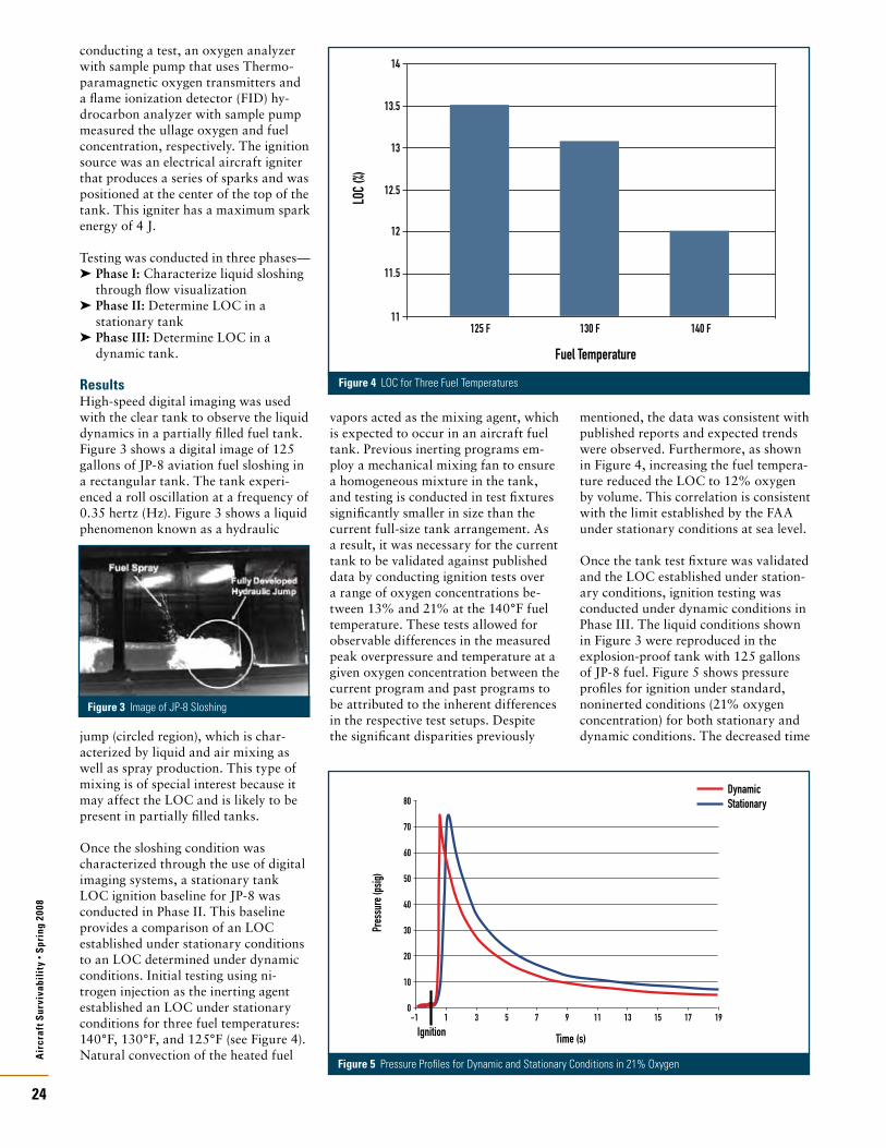
Air
craf
t Sur
viva
bili
ty •
Spri
ng 2
008
24
conducting a test, an oxygen analyzer with sample pump that uses Thermo-paramagnetic oxygen transmitters and a flame ionization detector (FID) hy-drocarbon analyzer with sample pump measured the ullage oxygen and fuel concentration, respectively. The ignition source was an electrical aircraft igniter that produces a series of sparks and was positioned at the center of the top of the tank. This igniter has a maximum spark energy of 4 J.
Testing was conducted in three phases—Phase I: ➤ Characterize liquid sloshing through flow visualizationPhase II: ➤ Determine LOC in a stationary tankPhase III: ➤ Determine LOC in a dynamic tank.
ResultsHigh-speed digital imaging was used with the clear tank to observe the liquid dynamics in a partially filled fuel tank. Figure 3 shows a digital image of 125 gallons of JP-8 aviation fuel sloshing in a rectangular tank. The tank experi-enced a roll oscillation at a frequency of 0.35 hertz (Hz). Figure 3 shows a liquid phenomenon known as a hydraulic
jump (circled region), which is char-acterized by liquid and air mixing as well as spray production. This type of mixing is of special interest because it may affect the LOC and is likely to be present in partially filled tanks.
Once the sloshing condition was characterized through the use of digital imaging systems, a stationary tank LOC ignition baseline for JP-8 was conducted in Phase II. This baseline provides a comparison of an LOC established under stationary conditions to an LOC determined under dynamic conditions. Initial testing using ni-trogen injection as the inerting agent established an LOC under stationary conditions for three fuel temperatures: 140°F, 130°F, and 125°F (see Figure 4). Natural convection of the heated fuel
vapors acted as the mixing agent, which is expected to occur in an aircraft fuel tank. Previous inerting programs em-ploy a mechanical mixing fan to ensure a homogeneous mixture in the tank, and testing is conducted in test fixtures significantly smaller in size than the current full-size tank arrangement. As a result, it was necessary for the current tank to be validated against published data by conducting ignition tests over a range of oxygen concentrations be-tween 13% and 21% at the 140°F fuel temperature. These tests allowed for observable differences in the measured peak overpressure and temperature at a given oxygen concentration between the current program and past programs to be attributed to the inherent differences in the respective test setups. Despite the significant disparities previously
mentioned, the data was consistent with published reports and expected trends were observed. Furthermore, as shown in Figure 4, increasing the fuel tempera-ture reduced the LOC to 12% oxygen by volume. This correlation is consistent with the limit established by the FAA under stationary conditions at sea level.
Once the tank test fixture was validated and the LOC established under station-ary conditions, ignition testing was conducted under dynamic conditions in Phase III. The liquid conditions shown in Figure 3 were reproduced in the explosion-proof tank with 125 gallons of JP-8 fuel. Figure 5 shows pressure profiles for ignition under standard, noninerted conditions (21% oxygen concentration) for both stationary and dynamic conditions. The decreased time
Figure 3 Image of JP-8 Sloshing
Figure 4 LOC for Three Fuel Temperatures
Fuel TemperatureLO
C (%)
13.5
14
13
12.5
12
11.5
11125 F 130 F 140 F
Time (s)Ignition
Pres
sure
(psig
) 50
80
60
70
40
30
20
10
0-1 1 3 5 7 9 11 13 15 17 19
DynamicStationary
Figure 5 Pressure Profiles for Dynamic and Stationary Conditions in 21% Oxygen

Air
craf
t Sur
viva
bili
ty •
Spri
ng 2
008
25
to peak pressure and the shorter dura-tion of the pulse suggests that dynamic conditions change the combustion characteristics in the tank.
The LOC was determined under dynamic conditions for a fuel tempera-ture of 130°F, and Figure 6 shows the results of the LOC testing. In Figure 6, the peak reaction pressure is plotted at different ullage oxygen concentrations. A few tests were conducted between 13% and 21% oxygen concentration to compare with stationary data obtained in this region that was used to validate the test facility. As expected, the peak pressure increases with increasing oxy-gen concentration, which is consistent with past data and was observed in the stationary data. When the 130°F fuel temperature was tested under dynamic conditions, a dramatic decrease in the LOC was observed. Under stationary conditions, the LOC for this fuel tem-perature was approximately 13%; how-ever, an oxygen concentration decrease of 2% was observed with the dynamic LOC measured at 11%. This limit is also below the 12% LOC at the 140°F temperature and the value observed by the FAA under stationary conditions. Because this fuel temperature is slightly above the minimal fuel temperature needed to produce flammable vapors, it is therefore influenced by the additional mixing produced by the dynamic motion.
The current test program shows that the LOC design criteria for OBIGGS must account for dynamic conditions that could exist in a fuel tank bay under typical flight environments. Typical OBIGGS would operate similarly to the procedures used in the test program with
direct injection of nitrogen into the ul-lage without the presence of a secondary mixing source to ensure a homogeneous mixture. The current suggested require-ment by the Bureau of Mines of 12%, reinforced through recent FAA testing, may not be a safe inerting level for commercial aircraft. However, the cur-rent 9% military requirement appears sufficient in protecting against ignition from electrically based sources.
Future TestingBecause dynamic conditions appear to affect the LOC, future testing that focuses on practical, real-life situations is desired. This testing includes devel-oping a flight plan to produce a range of three-dimensional motions for the motion simulator as well as simulating pressure altitude changes in the ullage during the simulation. Also, testing of multiple types of ignition sources, including those that are chemically and electrically based with a range of energy levels, is needed. Furthermore, this unique facility can be utilized for the testing and evaluation of current and next-generation inerting systems under dynamic fuel tank motion before actual flight testing. n
About the AuthorsDr. Peter Disimile is an Associate Professor in the Department of Aerospace Engineering at the University of Cincinnati. For the past several years, he has been detailed to the United States Air Force (USAF) 780 Test Squadron, Aircraft Survivability and Safety Flight at Wright-Patterson AFB. His interest is mainly in experimental fluid dynamics and heat transfer applied to fire and explosions issues. He has written
more than 180 journal and conference publications and abstracts ranging from acoustic behavior of cavity flows to temperature measurements in a pyrotechnic event, fire ignition, and hydrodynamic ram events.
Dr. Norman Toy is the Chief Engineer at Engineering and Scientific Innovations in Blue Ash, OH. He joined the company in January 2007 after a long career at the University of Surrey in the United Kingdom as a full-time professor in fluid mechanics. He is now a permanent resident of the United States and is involved in overseeing the programs associated with characterization of fire hazard and suppression for aircraft survivability.
John Pyles is a Research Engineer at Engineering and Scientific Innovations in Blue Ash, OH. He performs his work for the USAF at Wright-Patterson AFB. He received his M.S. in aerospace engineering from the University of Cincinnati and his B.S. in physics at Denison University. His main area of research is in aircraft survivability, and he has worked on multiple programs involving fire detection, characteriza-tion, and suppression in aircraft fuel tanks and engine nacelles. His findings have been presented at domestic and international conferences and docu-mented in technical reports.
ReferencesNTSB, “Safety Recommendation A-96-174,” 1. Issued 13 December 1996.Summer, S. M., “Limiting Oxygen Concentration 2. Required to Inert Jet Fuel Vapors Existing at Reduced Fuel Tank Pressures,” FAA, DOT/FAA/ARTN-02/79, Washington, DC, August 2003.Summer, S. M., “Limiting Oxygen Concentrations 3. for Fuel Tank Inerting,” Aircraft Survivability, Fall 2005, pp. 10–13.Kuchta, J. M., “Oxygen Dilution Requirements for 4. Inerting Aircraft Fuel Tanks,” Second Conference on Fuel System Fire Safety, Bureau of Mines Safety Research Center, Washington, DC, May 1970, pp. 85–115.Tyson, J. H. and J. F Barnes, “The Effectiveness 5. of Ullage Nitrogen-Inerting Systems Against 30-mm High-Explosive Incendiary Projectiles,” Report JTCG/AS-90-T-004, May 1991.Ferrenberg, A.J. and E.E. Ott, “Incendiary Gunfire 6. Simulation Techniques for Fuel Tank Explosion Protection Testing,” AFAPL-TR-73-50, July 1973.NTSB, “NTSB Most Wanted List Transportation 7. and Safety Improvements 2007–2008,” http://www.ntsb.gov/recs/mostwanted/index.htm.
Figure 6 Peak Pressure for Different Oxygen Concentration Under Dynamic Conditions
Oxygen Concentration (%)
Peak
Pres
sure
(psig
)
50
80
60
70
40
30
20
10
00 1 2 3 4 5 6 7 8 9 11 1210 13 14 15 16 17 18 19 20 21 22 23
Dynamic Conditions130 F ignition
140F 130F 125F
130 F (no ignition)
Stationary Conditions

Air
craf
t Sur
viva
bili
ty •
Spri
ng 2
008
26
Beginning with the 2007 Symposium, the former NDIA Combat Survivability Award for Leadership was renamed the Admiral Robert H. Gormley Leadership Award. This action was taken by unanimous vote of the Combat Survivability Division (CSD) Executive Board in honor of the CSD’s founder and former Chairman.
The inaugural Admiral Robert H. Gormley Leadership Award was pre-sented to Mr. John J. Campbell of General Electric (GE) Aviation. The NDIA Combat Survivability Award for Technical Achievement was presented to Mr. Dennis Elking, Boeing Senior Technical Fellow. These awards were presented at the 2007 Aircraft Survivability Symposium, “The Synergy of Electronic Combat and Complementary Survivability Technologies,” held 6–9 November 2007 at the Naval Postgraduate School (NPS) in Monterey, CA. Mr. Roland P. Marquis, Aircraft Survivability 2007 Chairman and CSD Awards Committee Chairman, and Major General John W. Hawley, U.S. Air Force (USAF) Ret., CSD Chairman made the presentations.
Admiral Robert H. Gormley Leadership AwardThe Admiral Robert H. Gormley Leadership Award is presented annually to a person who has made major contributions to enhancing combat survivability. The individual selected must have demonstrated outstanding leader-ship in enhancing the overall discipline of combat survivability, or must have played a significant role in a major aspect of survivability design, program manage-ment, research and development, modeling and simulation, test and evaluation, education, or standards
development. This award emphasizes demonstrated superior leadership of a continuing nature. The 2007 Admiral Robert H. Gormley Leadership Award was presented to Mr. John J. Campbell for exceptional leadership in the field of aircraft combat survivability.
Mr. Campbell has led a generation of military and industrial professionals in the establishment, development, and execution of advanced technology government and industry programs. Mr. Campbell’s 22-year USAF career, which included more than 100 Special Operations combat missions in Southeast Asia, involved assignments as diverse as Senior Navigator, Weapons Effect Officer, Test Director—Combined Force Strategic Systems, and Low Observables Technology Director. He co-founded a low observables technology organization that continues today as a legacy of his vision and accomplishments. The
technology developed and implemented by this organization has enabled USAF aircraft to accomplish critical missions that continue on a daily basis.
Following his USAF retirement, Mr. Campbell was Proprietary Programs Director of the GE Military Systems Organization. During his 16-year GE career, he directed the conduct of advanced research projects dealing with signature management of current and future weapons systems. His work included classified activities in materials, manufacturing processes, conceptual designs of propulsion solutions, and new advanced cycle approaches. Under his direction, GE’s low observables technol-ogy business organization greatly expanded its scope, personnel, and diversity of technology and systems application. The technology developed and implemented under Mr. Campbell’s leadership has and will continue to
Annual National Defense Industrial Association (NDIA) Survivability Awards
by Mike Mikel
The National Defense Industrial Association’s (NDIA) Combat Survivability Awards are presented annually at the NDIA Combat Survivability Division’s Aircraft Survivability Symposium. These awards recognize individuals or teams who have demonstrated superior performance across the entire spectrum of survivability, including susceptibility reduction, vulnerability reduction, and related modeling and simulation.
From left to right—Mr. Roland P. Marquis, CSD Awards Committee Chairman; Mr. John J. Campbell, 2007 Admiral Robert H. Gormley Leadership Award recipient; and Maj. Gen. John W. Hawley (USAF Ret.), Chairman, NDIA Combat Survivability Division

Air
craf
t Sur
viva
bili
ty •
Spri
ng 2
008
27
enable U.S. military platforms to accomplish their missions and save the lives of service men and women through low observable technology.
NDIA Combat Survivability Award for Technical AchievementThe NDIA Combat Survivability Award for Technical Achievement is presented annually to a person or team that has made a significant technical contribution to any aspect of survivability. It may be presented for a specific act or contribu-tion or for exceptional technical perfor-mance over a prolonged period. Individuals at any level of experience are eligible for this award. The 2007 CSD Technical Achievement Award was presented to Mr. Dennis Elking in recognition of his exceptional technical achievement in the field of aircraft combat survivability.
During the course of a 36-year career, Mr. Elking has consistently demonstrated exceptional technological expertise and is currently identified as the Boeing Corporation Low Observable design and analyses technology thrust leader. In 1985 Mr. Elking led the Computational Electromagnetics group. This group developed the high-frequency CADDSCAT code that calculates the physical theory of diffraction for Computer Aided Design (CAD) aircraft models. He has provided technical design support to a variety of programs, including the YF-23, LHX, and F/A-18E/F, and a number of highly classified programs. In 1998 Mr. Elking was a key member of the Bird of Prey aircraft design team, which led to his appointment as a Boeing Senior Technical Fellow the following year.
Mr. Elking’s other responsibilities and assignments include leading the A/FX LO Integration Team, where he pioneered the introduction of supercomputers for calculating aircraft signatures. This team’s application of three-dimensional method-of-moments codes resulted in more than two orders of magnitude greater capacity than previously existed. He introduced the use of PC clusters in the design of LO aircraft. These efforts were directly responsible for the success-ful testing of the X-45C Full-Scale Pole Model in 2006.
Best Poster Paper AwardsAwards were also presented for the best poster papers displayed as part of the symposium’s Exhibits and Poster Papers feature. Three awards were presented.
First place went to Mr. Dennis Williams and Ms. Michelle Kristofik, The Boeing Company, St. Louis, MO, for their paper “Commercial Derivative Aircraft Vulnerability Assessment.” Second place went to Mr. Kevin Crosthwaite, Booz Allen Hamilton, Dayton, OH, for his paper “Aircraft Vulnerability Workshop.” Third place went to Ms. Jennifer McCormick, Aerojet, Redmond, WA, for her paper “Solid Propellant Fire Extinguisher and Hybrid Fire Extinguisher.”
Aircraft Survivability 2008Preparations are now underway for the 2008 Aircraft Survivability Symposium, “Low Altitude Today, Preparing for Tomorrow.” Scheduled for 4–7 November 2008, this important event will provide a forum to explore how we can best balance our resources to meet the challenges of fighting the Global
War on Terror at low altitude while remaining prepared for the next major conflict. Watch for the 2008 call for presentations and 2008 CSD survivabil-ity award nominations. n
About the AuthorDr. T. N. (Mike) Mikel is the U.S. Marine Corps AH-1Z Build New IPT Leader at Bell Helicopter Textron Inc. He has more than 25 years of experience in the rotary wing aircraft design and survivability disciplines at Bell. He is a former U.S. Army Aviator and Infantry Officer. He holds a B.S. and two M.S. degrees from Texas A&M University and a Ph.D. from the University of Texas at Arlington. Dr. Mikel has been a member of the NDIA CSD Executive Board since 2000 and currently serves as the Communications and Publicity Committee Chair.
From left to right—Mr. Roland P. Marquis, CSD Awards Committee Chairman; Mr. Dennis Elking, Technical Achievement Award recipient; and Maj. Gen. John W. Hawley (USAF Ret.), Chairman, NDIA Combat Survivability Division
From left to right—Poster paper winners Ms. Jennifer McCormick, Ms. Michelle Kristofik, Mr. Dennis Williams, and Mr. Kevin Crosthwaite
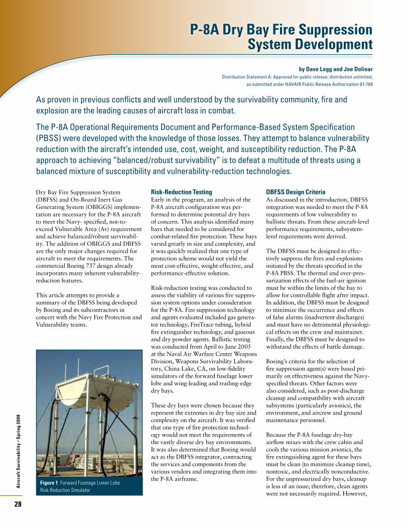
Air
craf
t Sur
viva
bili
ty •
Spri
ng 2
008
28
Dry Bay Fire Suppression System (DBFSS) and On-Board Inert Gas Generating System (OBIGGS) implemen-tation are necessary for the P-8A aircraft to meet the Navy- specified, not-to-exceed Vulnerable Area (Av) requirement and achieve balanced/robust survivabil-ity. The addition of OBIGGS and DBFSS are the only major changes required for aircraft to meet the requirements. The commercial Boeing 737 design already incorporates many inherent vulnerability-reduction features.
This article attempts to provide a summary of the DBFSS being developed by Boeing and its subcontractors in concert with the Navy Fire Protection and Vulnerability teams.
Risk-Reduction TestingEarly in the program, an analysis of the P-8A aircraft configuration was per-formed to determine potential dry bays of concern. This analysis identified many bays that needed to be considered for combat-related fire protection. These bays varied greatly in size and complexity, and it was quickly realized that one type of protection scheme would not yield the most cost-effective, weight-effective, and performance-effective solution.
Risk-reduction testing was conducted to assess the viability of various fire suppres-sion system options under consideration for the P-8A. Fire suppression technology and agents evaluated included gas genera-tor technology, FireTrace tubing, hybrid fire extinguisher technology, and gaseous and dry powder agents. Ballistic testing was conducted from April to June 2005 at the Naval Air Warfare Center Weapons Division, Weapons Survivability Labora-tory, China Lake, CA, on low-fidelity simulators of the forward fuselage lower lobe and wing-leading and trailing-edge dry bays.
These dry bays were chosen because they represent the extremes in dry bay size and complexity on the aircraft. It was verified that one type of fire protection technol-ogy would not meet the requirements of the vastly diverse dry bay environments. It was also determined that Boeing would act as the DBFSS integrator, contracting the services and components from the various vendors and integrating them into the P-8A airframe.
DBFSS Design Criteria As discussed in the introduction, DBFSS integration was needed to meet the P-8A requirements of low vulnerability to ballistic threats. From these aircraft-level performance requirements, subsystem-level requirements were derived.
The DBFSS must be designed to effec-tively suppress the fires and explosions initiated by the threats specified in the P-8A PBSS. The thermal and over-pres-surization effects of the fuel-air ignition must be within the limits of the bay to allow for controllable flight after impact. In addition, the DBFSS must be designed to minimize the occurrence and effects of false alarms (inadvertent discharges) and must have no detrimental physiologi-cal effects on the crew and maintainer. Finally, the DBFSS must be designed to withstand the effects of battle damage.
Boeing’s criteria for the selection of fire suppression agent(s) were based pri-marily on effectiveness against the Navy-specified threats. Other factors were also considered, such as post-discharge cleanup and compatibility with aircraft subsystems (particularly avionics), the environment, and aircrew and ground maintenance personnel.
Because the P-8A fuselage dry-bay airflow mixes with the crew cabin and cools the various mission avionics, the fire extinguishing agent for these bays must be clean (to minimize cleanup time), nontoxic, and electrically nonconductive. For the unpressurized dry bays, cleanup is less of an issue; therefore, clean agents were not necessarily required. However,
P-8A Dry Bay Fire Suppression System Development
by Dave Legg and Joe Dolinar Distribution Statement A: Approved for public release; distribution unlimited,
as submitted under NAVAIR Public Release Authorization 07-768
As proven in previous conflicts and well understood by the survivability community, fire and explosion are the leading causes of aircraft loss in combat.
The P-8A Operational Requirements Document and Performance-Based System Specification (PBSS) were developed with the knowledge of those losses. They attempt to balance vulnerability reduction with the aircraft’s intended use, cost, weight, and susceptibility reduction. The P-8A approach to achieving “balanced/robust survivability” is to defeat a multitude of threats using a balanced mixture of susceptibility and vulnerability-reduction technologies.
Figure 1 Forward Fuselage Lower Lobe Risk-Reduction Simulator

Air
craf
t Sur
viva
bili
ty •
Spri
ng 2
008
29
compatibility with other systems in the bay was considered.
All agents were required to be non-ozone depleting. To meet the structural limits of the various dry bays, the detection system and system controllers were designed to reduce overpressures associated with the fuel vapor explosion.
Development TestingThe next phase of the DBFSS develop-ment required a significant amount of sensitive data sharing between Boeing Integrated Defense Systems (IDS), Boeing Commercial Airplanes (BCA), and the Navy. This was necessary because the Navy Weapons Survivability Labora-tory in China Lake, CA, was responsible for the design and construction of high-fidelity “iron bird” simulators. A cooperative task of this magnitude has never been attempted before in the Department of Defense (DoD) and com-mercial aircraft environment.
As a precursor to ballistic testing of the iron-bird simulators, Boeing constructed plywood mockups of several dry bays for nonballistic testing, which they used to obtain preliminary assessments of fire suppression agent concentration distribu-tion in a given bay. These test series aided in the initial quantity and placement of suppressors and minimized the number of shots required for the development of each system.
The Navy-Boeing team determined projectile shot lines for each ballistic test based on potential threat engage-ment geometries and fire probability. It assessed probability based on engineering judgment, the Computation of Vulnerable Area Tool (COVART), the Fire Prediction Model and, as test experience was gained, previous test results.
Although iron-bird simulators were used to ensure the longevity and survivability of the test article, Boeing supplied actual aircraft panels to achieve realistic results when necessary. The potential for panels to depart the simulator was one of the concerns because it would cause a mas-sive induction of airflow and consequent-ly influence the fire and performance of the DBFSS. In one test series, it was proposed that the airflow contributed to the lack of a sustained fire. To ensure this was not a misleading result, several shots with various external airflow velocities were taken.
Detailed clutter was also incorporated in the iron-bird simulators. Before conduct-ing each test series, the Navy-Boeing team reviewed the bay in detail to determine fuel loads and temperatures, bay airflow conditions, hydraulics, and fuel and electrical systems that could influence the fire threat and pertinent bay clutter. This clutter included wiring, ducting, tubing, structure, and other items that could affect airflow or fuel drain paths or could act as flame holders. Where appropriate, ducting included internal airflow, and tubing included flammable fluids.
The test locations of optical fire detectors and fire suppressant bottles were based on viable locations on the actual aircraft. Boeing engineers worked with their system integrators to evaluate the system layout, identify any potential integration issues, and develop alternative system architecture if fire testing proved certain locations were inadequate. In some instances, various locations were tested to provide alternative locations and design flexibility.
DBFSS Design and IntegrationAs a result of the risk-reduction testing, development testing, and design criteria described above, the current DBFSS design consists of the following—
FE-36 suppressors with dual infrared ➤
detectors and thermistors in pressur-ized lower lobe baysMonnex suppressors with ➤
dual infrared detectors in unpressur-ized areasFireTrace tube with HFC-125 ➤
suppressor in wing leading edgeFireTrace tube with HFC-125 ➤
suppressor in wing trailing edge
Control of the DBFSS is achieved through the Fire Protection Control Units (FPCU) distributed throughout the aircraft. Each DBFSS will have a primary controller and a separate backup controller to minimize any adverse effects from battle damage.
To minimize the occurrence of false alarms, the FPCU discharge logic will require two valid independent fire detec-tion signals from the same bay. This
dual-logic control system is similar to the system employed on other Navy aircraft to mitigate the same problem. If a fire detector becomes inoperable, the FPCU control logic will revert to a single fire alarm control.
Finally, if an inadvertent discharge should occur, the DBFSS FPCU will record which component was activated (suppres-sor discharge or detector alarm) and the time it occurred. This information will help identify the root cause in the ensuing engineering investigation.
Boeing is currently working on the detailed integration of these DBFSS components in their respective aircraft bays. The development testing results will determine the locations of these components.
SummaryTo date, there have been more than 200 ballistic tests in support of the P-8A Live Fire Test and Evaluation program. The vast majority have supported the develop-ment of the DBFSS. Although testing and design of the DBFSS is not fully complete and some integration issues remain, the Navy-Boeing team has been successful thus far. All indications are that the P-8A design will meet its Av requirements and the goal of a balanced/robust survivability design will be achieved. n
About the AuthorsDave Legg is currently the Lead Survivability Project Officer for the P-8A Multi-Mission Maritime Aircraft (MMA) in the Aircraft Survivability Division of the Naval Air Systems Command (NAVAIR) at Patuxant River, MD. Please see “Excellence in Survivability” on pages 12–13 for more information.
Joseph Dolinar is the P-8A Fire and Explosion Team Lead for the Naval Air Systems Command, Patuxent River, MD. He is responsible for the design, development and integration of the P-8A Dry Bay Fire Suppression Systems, fuel tank inerting systems and overall fire safety o the aircraft. He also serves as the NAVAIR Fire Protection Team Lead.
Figure 3 P-8A Poseidon
Figure 2 P-8A Main Landing Gear Bay “Iron Bird” Simulator
Air
craf
t Sur
viva
bili
ty •
Spri
ng 2
008
30
The objective of the workshop was to address the issue of vulnerability and low-vulnerability technology in a realistic and equitable manner throughout the aircraft acquisition process, from the early capability requirements phases through full-rate production. To accomplish that objective, the workshop participants identified the steps necessary to better understand the current VR problem and proposed better methods for evaluating VR technologies. The ultimate goal of the workshop is to reduce the vulnerability of current and future aircraft. Sixty leading experts on VR and key figures in the Department of Defense (DoD) acquisition community were invited to and participated in the workshop.
The workshop was planned and orga-nized based on three premises—
Current Analysis of Alternatives ➤
(AoA) methodologies understate the important contributions of VR to the cost-effectiveness of air combat systems. A fair evaluation of VR’s contribution ➤
to combat effectiveness may require developing better VR metrics. The rising cost of weapons systems ➤
and the American public’s sensitivity to casualties should motivate DoD decisionmakers to consider improvements to VR requirements and methods.
Current terrorist threats focus on producing casualties. This focus has led to many efforts to retrofit VR into existing aircraft platforms even though retrofitting is the most expensive way to reduce vulnerability. The intent of the workshop was to avoid that belated retrofit effort in the future by finding
ways to improve vulnerability evaluations and implement VR early in the acquisi-tion process. Ultimately, it is hoped that VR features will achieve greater accep-tance by program managers as new lightweight materials arise to prevent vehicle penetration and new technologies are developed for fire suppression and damage effect mitigation.
Workshop FindingsAoAs conducted as joint campaign-level analyses currently drive the evaluation process. These AoA often sacrifice the engineering details that demonstrate the contributions of VR to aircraft surviv-ability and mission effectiveness. Because the higher level models often capture vulnerability features only in an aggre-gated probability of kill (Pk) matrix, it is easy to lose fidelity in the nuances and advantages of low vulnerability. Typical measures of effectiveness used in AoA lack sensitivity to VR. The choice of scenarios in the AoA process and the resulting likelihood of encountering various threats also are huge factors in driving the perception of VR’s value to aircraft programs.
Case histories presented at the workshop demonstrate differing experiences between fixed wing, rotary wing, and large/transport aircraft when applying VR technologies—
Fixed Wing ➤ —The experience of the Joint Strike Fighter (JSF) program in dealing with low-vulnerability issues demonstrates that VR is not sufficient to establish solid low-vulnerability specifications at the start of a program. As programs progress through engineering development, all require-ments are continually reviewed, challenged, and possibly revised. Even
with diligent defense, low-vulnerability features can be lost from the design. Ultimately, the operator’s perception of the importance of low vulnerability is critical to maintaining low-vulnerabili-ty features when faced with hard design tradeoffs.Rotary Wing ➤ —Examples of VR in the design of rotorcraft (V-22 and H-1 upgrades) presented a more positive perspective of the rotorcraft commu-nity’s ability to keep low-vulnerability features in the design, from early phases through aircraft fielding. The different and challenging threat environment that helicopters experi-ence when operating at low altitudes drives this perspective. Rotary wing operators are intensely aware of the threat and are motivated to maintain all key low-vulnerability features. Large Aircraft ➤ —Particular issues are involved in adapting a commercial Boeing 737 aircraft for the P-8A Multi-Mission Maritime Aircraft (MMA) program, with its inherent vulnerability and size, to accommo-date additional features necessary to meet a combat threat environment. In some cases, the P-8 program has utilized a probability-of-hit metric in design analyses, which ignores the contributions of low-vulnerability features; against other threats, the program has used a vulnerability-sensitive Pk-given hit as the metric. The program also has defined a kill criterion involving a longer time period than normally used in the analysis process to address a multiperson crew’s ability to evacuate.
Personnel casualty key performance parameters (KPP) and LFT&E laws also affect VR. Focusing additional attention
On 17 May 2007, the National Defense Industrial Association’s (NDIA) Combat Survivability Division (CSD) conducted a workshop on aircraft Vulnerability Reduction (VR) hosted by the Institute for Defense Analyses (IDA). The Deputy Director, Operational Test and Evaluation/Live Fire Test and Evaluation (DDOT&E/LFT&E) sponsors this workshop. The selection of VR as the workshop topic for 2007 was based on the results of a survey of Aircraft Survivability 2006 symposium participants and on the current importance of this issue to the warfighter.
Vulnerability Reduction (VR) Workshopby Kevin Crosthwaite and David Hall

Air
craf
t Sur
viva
bili
ty •
Spri
ng 2
008
31
on expected casualties during the design and evaluation phases should help further promote VR features. Using “casualties as an independent variable” would address both expected casualties and aircraft kill. Emphasizing design changes that improve both safety and survivability (e.g., fire suppression systems) also will reduce total losses of aircraft and all occupants in both peacetime and combat.
All participants agreed that a VR problem exists. However, the problem manifests itself differently for different types of platforms and threat environ-ments. Similarly, the priority of solutions is different depending on the platform type. VR requirements and associated technologies have been traded away early in the design phase of programs unless they are explicitly tied to specific survivability KPP and challenging mission use cases. The mission use cases that are analyzed both in the requirements and design process and as part of the AoA are not sufficiently robust in terms of vulnerability issues. We design to the war we want to fight rather than the war the threat forces us to fight. We must address the dilemma of how to trade off weight, cost, and effectiveness for VR equip-ment. For commercial aircraft, the potential commercial off-the-shelf (COTS) acquisitions are seen as both a challenge and an opportunity to implement VR features.
Each of the fighter, rotorcraft, and transport breakout sessions identified several specific programs and types of programs that would benefit from increased VR focus and new technology-driven options. A wide variety of responses from the different breakout sessions resulted. This detailed and
platform-specific perspective was one of the most valuable outcomes of the workshop. It was also a direct result of the active participation of each of the communities in their respective breakout sessions.
RecommendationsBased on inputs from the workshop participants, the NDIA Aircraft Combat Survivability Division recommends that the DoD—
Set reasonable and achievable VR 1. specifications. Over-specification can set the bar too high, resulting in too much program risk and, ultimately, rejection of the associated vulnerability technology. Under-specification can result in the unnecessary loss of aircraft in combat.Ensure key challenging scenarios are 2. chosen to more realistically and equitably consider VR decisions in the trade space with other survivability and performance metrics.Develop more meaningful VR metrics 3. involving expected casualties, sustain-ability, and links to safety.Better represent VR in mission and 4. campaign-level analyses to evaluate the value add of VR features.Educate program managers and 5. operators on VR options and consequences. Challenge and invest more in new 6. materials research to provide future out-of-the-box solutions to lightweight penetration prevention and damage tolerance—such as self-healing materials or nanotechnology aircraft skin that better resists penetration. The goal is to develop VR technologies for ready or low-risk use during system design and development phases and to present new low-vulnerability options for designers and program offices.
The Office of the Under Secretary of Defense for Acquisition, Technology, and Logistics (OUSD/AT&L) could direct some of these recommendations. Other actions (such as 3, 4, and 5) would require further work by other agents, such as the Joint Aircraft Survivability Program (JASP).
SummaryThere is a problem in successfully implementing vulnerability reduction in current aircraft systems that results in more vulnerable aircraft, or in costly retrofit of vulnerability reduction features due to combat losses. Careful review and consideration of the recommendations of the NDIA VR Workshop Report should be a first step toward improving aircraft survivability and force protection. The NDIA recommendations will improve VR against the wide variety of systems that threaten our forces and will reduce aircraft and personnel losses. These recommendations would lead to more cost-effective VR for aircraft and, ultimately, better force protection. n
About the AuthorsKevin Crosthwaite is Director of the Survivability/Vulnerability Information Analysis Center (SURVIAC). He has worked on several technical analysis and test programs involving a wide variety of weapons systems. Mr. Crosthwaite has a masters in nuclear physics from Ohio State and is a licensed professional engineer. He serves on the NDIA Combat Survivability Division Executive Board and on the AIAA Survivability Technical Committee.
David Hall is the Chief Analyst for SURVICE Engineering Company, under contract to the NAWCWD Survivability Division for analysis support services. SURVICE provides the Navy with analyses of air weapon systems, test, and analysis support services; and simulation and software support including model W&A. Before his retirement from the government in January 2002, he was Chief Analyst of the NAWCWD Survivability Division, head of the Survivability Methodology Subgroup for JASPO, and interim JASA Director. From 1992–1996, he was also the Joint Project Manager of the SMART project, which developed and demonstrated Joint M&S VV&A and configuration-manage-ment processes for DoD. Mr. Hall has Bachelor of Science and Master degrees in mathematics from California State University at Long Beach, CA.
References1. NDIA, Combat Survivability Division, Vulnerability Reduction Workshop Report, May 2007

Calendar of Events
Information for inclusion in the
Calendar of Events may be sent to:
SURVIAC, Washington Satellite Office
Attn: Christina McNemar
13200 Woodland Park Road, Suite 6047
Herndon, VA 20171
COMMANDERNAVAL AIR SYSTEMS COMMAND (4.1.8J)47123 BUSE ROADPATUXENT RIVER, MD 20670-1547
Official Business
PRSRT STDU.S. POSTAGE
PAIDPAX RIVER MDPermit No. 22
APRDTIC’s 34th Annual Conference: “Protecting While Sharing Defense Information”7–8 April 2008 Alexandria, VA http://www.dtic.mil/dtic/annualconf
2008 JASP Aircraft Combat Survivability Short Course14–17 April 2008 Monterey, CA http://www.bahdayton.com/jasp2008
Precision Strike Annual Programs Review15–16 April 2008 Springfield, VA http://www.precisionstrike.org/index.htm
2008 C4ISR T&E in a Joint Testing and Training Environment15–17 April 2008 Fort Walton Beach, FL http://itea.org
Gun & Missiles Symposium21–24 April 2008 New Orleans, LA http://ndia.org/Template.cfm?Section=Meetings_and_Events
Joint Combat Assessment Team (JCAT) 2008 Threat Weapons and Effects Training Seminar21–25 April 2008 Hurlburt Field and Eglin AFB. https://www.bahdayton.com/jcat2008
15th AIAA International Space Planes and Hypersonic Systems and Technologies Conference28 April–1 May 2008 Dayton, OH http://www.aiaa.org/content.cfm?pageid=230&lumeetingid=1877
2008 Marine Corps Systems Command/APBI13–14 April 2008 Baltimore, MD http://www.ndia.org/Template.cfm?Section=8900&Template=/ContentManagement/ContentDisplay.cfm&ContentID=21698
MAYStrike, Land Attack & Air Defense (SLAAD) Division Annual Symposium 20086 May 2008 Laurel, MD http://www.ndia.org/Template.cfm?Section=8100&Template=/ContentManagement/ContentDisplay.cfm&ContentID=21531
SpaceOps 2008 Conference12–16 May 2008 Heidelberg, Germany http://www.aiaa.org/content.cfm?pageid=230&lumeetingid=1436
International Infantry & Joint Services Small Arms Systems Symposium19–22 May 2008 Dallas, TX http://www.ndia.org/Template.cfm?Section=8610&Template=/ContentManagement/ContentDisplay.cfm&ContentID=17506
52nd Annual Fuze Conference13–15 May 2008 Sparks, NV http://www.ndia.org/Template.cfm?Section=8560&Template=/ContentManagement/ContentDisplay.cfm&ContentID=22063
JUNTest Week 2008:”Test and Evaluation for the Future: What Lies 10-15 Years Ahead?”2–5 June 2008 Huntsville, AL http://www.testweek.org
Defense Systems Acquisition Management Course (DSAM)9–12 June 2008 Denver, CO http://www.ndia.org/Template.cfm?Section=802C&Template=/ContentManagement/ContentDisplay.cfm&ContentID=20638
76th MORS Symposium10–12 June 2008 New London, CA http://www.aiaa.org/content.cfm?pageid=230&lumeetingid=1968&viewcon=submit
26th International Communications Satellite Systems Conference (ICSSC)10–12 June 2008 San Diego, CA http://www.aiaa.org/content.cfm?pageid=230&lumeetingid=1968&viewcon=submit
Transformation Warfare 200817–19 June 2008 Virginia Beach, VA http://www.afcea.org
Summer JMUM17–19 June 2008 Colorado Springs, CO http://www.bahdayton.com/surviac