An Infrared Camera for Leuschner Observatory and the ...
15
607 Publications of the Astronomical Society of the Pacific, 113:607–621, 2001 May 2001. The Astronomical Society of the Pacific. All rights reserved. Printed in U.S.A. An Infrared Camera for Leuschner Observatory and the Berkeley Undergraduate Astronomy Lab James R. Graham and Richard R. Treffers Astronomy Department, University of California, Berkeley, CA 94720-3411; [email protected], [email protected] Received 2001 January 10; accepted 2001 January 19 ABSTRACT. We describe the design, fabrication, and operation of an infrared camera which is in use at the 30 inch telescope of the Leuschner Observatory. The camera is based on a Rockwell PICNIC pixel 256 # 256 HgCdTe array, which is sensitive from 0.9 to 2.5 mm. The primary purpose of this telescope is for undergraduate instruction. The cost of the camera has been minimized by using commercial parts wherever practical. The camera optics are based on a modified Offner relay which forms a cold pupil where stray thermal radiation from the telescope is baffled. A cold, six-position filter wheel is driven by a cryogenic stepper motor, thus avoiding any mechanical feedthroughs. The array control and readout electronics are based on standard PC cards; the only custom component is a simple interface card which buffers the clocks and amplifies the analog signals from the array. 1. INTRODUCTION Many undergraduates enter universities and colleges with the ambition of pursing several science courses, or even a sci- ence major. Yet significant numbers take only the minimum requirements because science is often perceived as laborious, demanding, and irrelevant. The result is graduates whose lives and careers as citizens are not enriched by an understanding of science or technology. Since the Astronomy Department is frequently an undergraduate’s only contact with science, we have a tremendous responsibility as a provider of undergraduate science instruction. Unfortunately, the students who are cap- tivated by introductory astronomy often conclude that the as- tronomy major consists of narrow technical courses designed only for those intent on pursuing an academic career. These classes do not stress problem solving or critical thinking or emphasize the connections between broad areas of scientific knowledge. The Berkeley undergraduate astronomy labs offer an potent antidote to conventional lectures and stimulate stu- dents to pursue the astronomy major. We describe a state-of- the-art infrared camera which is used at Berkeley to inspire and instruct. Prior to the construction of this camera the undergraduate lab syllabus consisted of an optical and a radio class. The labs use theodolites, a CCD-equipped robotic observatory (Treffers, Richmond, & Filippenko 1992), and radio telescopes to provide the astronomical context to discuss the statistical description of experimental data, including the notions of errors, error prop- agation, and signal-to-noise ratio. These resources also provide students with a practical forum in which to explore signal pro- cessing techniques including power spectrum estimation and convolution. The optical labs are traditionally offered in the fall semester. The spring climate in northern California is unsuitable for optical observations, so a radio astronomy lab based on a rooftop 21 cm horn antenna and a two-element 12 GHz satellite dish interferometer are offered (Parthasarathy et al. 1998). These experiments have significant computational demands that involve least-squares fitting, precession, coordinate con- version, Doppler correction, Fourier transforms, and image pro- cessing. Students use a cluster of Sun Ultra workstations and the IDL programming environment for data reduction and anal- ysis. These machines provide, for example, the data storage and computational power required for four to five groups of students working simultaneously to turn the visibility data from the interferometer into radio maps. 1.1. Development of an Infrared Undergraduate Laboratory To maintain the intellectual vitality of the undergraduate lab, broaden the range of observing experiences we offer, and sat- isfy the demand for increased enrollment we have developed a new lab program based on the theme of infrared astronomy. Although radio receivers are commonplace, the notion of using radio technology for astronomy remains exotic. Radio astron- omy continues to exemplify astronomy of the “invisible uni- verse,” and detecting astronomical radio signals continues to intrigue and captivate students. Perhaps, because our eyes give us an intuitive sense of what it means to “see” at visible wave- lengths, and because CCDs have become commonplace in products such as digital cameras, the high-tech aspect of the optical lab has lost some of its gloss. Modern CCDs have excellent cosmetic quality, and students report that calibration of CCD images appears to consist of annoying minor correc- tions. Faint stars and galaxies are readily observable in raw CCD images. In contrast, at infrared wavelengths the brightness
Transcript of An Infrared Camera for Leuschner Observatory and the ...

607
Publications of the Astronomical Society of the Pacific, 113:607–621, 2001 May� 2001. The Astronomical Society of the Pacific. All rights reserved. Printed in U.S.A.
An Infrared Camera for Leuschner Observatory and theBerkeley Undergraduate Astronomy Lab
James R. Graham and Richard R. Treffers
Astronomy Department, University of California, Berkeley, CA 94720-3411; [email protected], [email protected]
Received 2001 January 10; accepted 2001 January 19
ABSTRACT. We describe the design, fabrication, and operation of an infrared camera which is in use at the30 inch telescope of the Leuschner Observatory. The camera is based on a Rockwell PICNIC pixel256# 256HgCdTe array, which is sensitive from 0.9 to 2.5mm. The primary purpose of this telescope is for undergraduateinstruction. The cost of the camera has been minimized by using commercial parts wherever practical. The cameraoptics are based on a modified Offner relay which forms a cold pupil where stray thermal radiation from the telescopeis baffled. A cold, six-position filter wheel is driven by a cryogenic stepper motor, thus avoiding any mechanicalfeedthroughs. The array control and readout electronics are based on standard PC cards; the only custom componentis a simple interface card which buffers the clocks and amplifies the analog signals from the array.
1. INTRODUCTION
Many undergraduates enter universities and colleges withthe ambition of pursing several science courses, or even a sci-ence major. Yet significant numbers take only the minimumrequirements because science is often perceived as laborious,demanding, and irrelevant. The result is graduates whose livesand careers as citizens are not enriched by an understandingof science or technology. Since the Astronomy Department isfrequently an undergraduate’s only contact with science, wehave a tremendous responsibility as a provider of undergraduatescience instruction. Unfortunately, the students who are cap-tivated by introductory astronomy often conclude that the as-tronomy major consists of narrow technical courses designedonly for those intent on pursuing an academic career. Theseclasses do not stress problem solving or critical thinking oremphasize the connections between broad areas of scientificknowledge. The Berkeley undergraduate astronomy labs offeran potent antidote to conventional lectures and stimulate stu-dents to pursue the astronomy major. We describe a state-of-the-art infrared camera which is used at Berkeley to inspireand instruct.
Prior to the construction of this camera the undergraduatelab syllabus consisted of an optical and a radio class. The labsuse theodolites, a CCD-equipped robotic observatory (Treffers,Richmond, & Filippenko 1992), and radio telescopes to providethe astronomical context to discuss the statistical descriptionof experimental data, including the notions of errors, error prop-agation, and signal-to-noise ratio.These resources also providestudents with a practical forum in which to explore signal pro-cessing techniques including power spectrum estimation andconvolution. The optical labs are traditionally offered in the fallsemester. The spring climate in northern California is unsuitable
for optical observations, so a radio astronomy lab based on arooftop 21 cm horn antenna and a two-element 12 GHz satellitedish interferometer are offered (Parthasarathy et al. 1998).
These experiments have significant computational demandsthat involve least-squares fitting, precession, coordinate con-version, Doppler correction, Fourier transforms, and image pro-cessing. Students use a cluster of Sun Ultra workstations andthe IDL programming environment for data reduction and anal-ysis. These machines provide, for example, the data storageand computational power required for four to five groups ofstudents working simultaneously to turn the visibility data fromthe interferometer into radio maps.
1.1. Development of an Infrared UndergraduateLaboratory
To maintain the intellectual vitality of the undergraduate lab,broaden the range of observing experiences we offer, and sat-isfy the demand for increased enrollment we have developeda new lab program based on the theme of infrared astronomy.Although radio receivers are commonplace, the notion of usingradio technology for astronomy remains exotic. Radio astron-omy continues to exemplify astronomy of the “invisible uni-verse,” and detecting astronomical radio signals continues tointrigue and captivate students. Perhaps, because our eyes giveus an intuitive sense of what it means to “see” at visible wave-lengths, and because CCDs have become commonplace inproducts such as digital cameras, the high-tech aspect of theoptical lab has lost some of its gloss. Modern CCDs haveexcellent cosmetic quality, and students report that calibrationof CCD images appears to consist of annoying minor correc-tions. Faint stars and galaxies are readily observable in rawCCD images. In contrast, at infrared wavelengths the brightness

608 GRAHAM & TREFFERS
2001 PASP,113:607–621
Fig. 1.—The off-axis Offner system relays the image atA to B with unitmagnification. The concave mirror and the convex mirror are concentricM M1 2
about the pointC. is placed halfway between and the focal planeABM M2 1
to give a zero Petzval sum, i.e., .R p �2R1 2
Fig. 2.—Spot diagrams for an F/8 Offner relay. The nine panels correspondto the center, edges, and corners of the PICNIC array. Each box is the size ofa single PICNIC pixel (40mm) and is labeled with its coordinates relative tothe center of curvature of and (pointC in Fig. 1). Dimensions are inM M1 2
millimeters. The geometric image size is limited by fifth-order astigmatism.
Fig. 3.—Spot diagrams for an F/8 corrected Offner relay. Layout is as inFig. 2. Increasing the radius of , while keeping it concentric with ,M M2 1
introduces enough third-order astigmatism to cancel fifth-order astigmatism atthe central field point.
of the sky (e.g., 13 mag arcsec�2 at K band), compounded bydetector flaws and artifacts, means that it is impossible to detectinteresting sources without sky subtraction and flat-fielding.Digging the infrared signal of optically invisible dust-enshrouded young stars out of noise can be presented as achallenging and worthwhile goal (cf. § 3.4).
Thus, infrared astronomy is a natural next step for an un-dergraduate observatory that is equipped with optical and radiofacilities. Moreover, infrared observations are becoming fa-miliar to students from introductory undergraduate text bookswhich rely on observations from theIRAS, ISO, and the NIC-MOS camera on theHubble Space Telescope to describe as-trophysical phenomena such as star formation. We can expectinterest to soar asSOFIA andSIRTF become operational in thenext few years. Infrared observations provide a unique contextto discuss a broad range of physical phenomena and astro-physical processes: blackbody radiation, solid state physics andthe operation of photon detectors, telescope optics, and ab-sorption and emission by dust and molecules.
Because of the complexities associated with cryogenic opticsneeded for operation at wavelengths longer than about 1.6mm,a prototype camera with a fixedH filter located immediatelyin front of the focal plane array was fielded for instructionalpurposes in the fall of 1999. This version of the camera pro-vided the opportunity to verify the operation of the array read-out electronics. A Mark II camera with cold reimaging opticsand a cryogenic filter wheel was constructed during summer2000 and used for a class conducted in the fall 2000 semester.
2. DESIGN OF THE INFRARED CAMERA
Given the restricted budgets available for undergraduate in-struction, the single most important factor influencing the de-sign of the camera is inevitably cost. Traditionally, infraredcameras require expensive custom components—cryogenicvacuum vessels, cryogenic mechanisms, optics, and array con-trol and readout electronics. We have controlled costs by adopt-ing a design which relies almost entirely on commercial parts.

LEUSCHNER OBSERVATORY INFRARED CAMERA 609
2001 PASP,113:607–621
Fig. 4.—Spot diagrams for the modified F/8 Offner based on 6 inch (152.4mm) focal length spherical primary and a mm secondary. LayoutR p 155.042
is as in Fig. 2. This design has a slight excess of third-order astigmatism butperfectly adequate and uniform performance of 5mm rms spots over the entirefield.
Fig. 5.—The Offner design is robust against misalignments. The spot dia-grams are for the modified F/8 Offner in Fig. 4, but with a 1� tilt of thesecondary about its vertex. The rms spot size is 11mm. A tilt of this amplitudeintroduces 5.2 mm of image motion, which is easily detected.
The heart of the camera is the infrared sensor. Owing to thegenerous support of the National Science Foundation and pro-vision of matching funds by Rockwell International, we wereable to procure an engineering grade HgCdTe PIC-256# 256NIC infrared focal plane array (Vural et al. 1999). The PICNICarray is a hybrid device with four independent quadrant outputs.This hybrid device is similar to Rockwell’s familiar NICMOS3array; it has identical unit cell size, number of outputs, andgeneral architecture, and uses a modified multiplexer designand better fabrication techniques to improve the noise and am-plifier glow. The PICNIC array detector material is HgCdTewith a band gap corresponding to 2.5mm. The requirement formoderate dark current (less than 102 e� s�1) necessitates op-eration below 100 K. A cold environment also is required tominimize the thermal radiation from room-temperature surfacesreaching the detector. A simple calculation shows that for-mation of a cold pupil to match the acceptance F-cone of thecamera to the telescope is necessary if useful operation inK band is expected from the instrument. Cold baffles aloneprovide an ineffective and impractical method of controllingthis thermal background.
2.1. Optical Design
The camera is designed to operate at the Cassegrain focusof the 30 inch telescope of Leuschner Observatory, which islocated 10 miles east of the Berkeley Campus in Lafayette.The 30 inch is a Ritchey-Chre´tien with a nominal F/8 final
focal ratio, yielding a scale of 33�.8 mm�1. The seeing atLeuschner is typically 2�–3� FWHM at visible wavelengths.At this scale the 40mm PICNIC pixels project to 1�.35 on thesky.
Direct imaging is a simple yet natural solution which takesadvantage of the large corrected field delivered by the Ritchey-Chretien design. Unfortunately, direct imaging is an unac-ceptable solution because of the detector’s sensitivity to thermalradiation. Consider installing the PICNIC array in a vacuumvessel typical of CCD dewars. Suppose, optimistically, that thecold, dark interior of the dewar restricts the solid angle ofambient radiation illuminating the detector to an F/3 cone. Theblackbody radiation from the instrument flange and primarymirror support structure at 293 K in this solid angle in anH-band filter (1.5–1.8mm) is 2500 photons s�1 pixel�1. Thisshould be compared with the sky signal of 6000 photons s�1
pixel�1 (for mag arcsec�2) and the detector dark currentH p 14of a few electrons per second per pixel. At (2.0–2.3mm)Ks
the unwanted thermal radiation is 2 orders of magnitude greater( photons s�1 pixel�1) than it is atH. In fall 1999 we54.5# 10deployed a prototype camera to test the array read-out elec-tronics, vacuum dewar, and closed-cycle He refrigerator. Tospeed the development we eliminated all optical componentsapart from a fixed filter that was located directly in front ofthe focal plane array. Stray radiation was controlled only by acold baffle tube. This configuration, as predicted, suffered fromhigh background to the extent that it was unusable in the
band because the detector became saturated in the minimumKs

610 GRAHAM & TREFFERS
2001 PASP,113:607–621
Fig. 6.—A drawing of the infrared camera dewar, optics, cold head, and mechanisms.
integration time (0.66 s). Both theory and practice show thatformation of a cold pupil within the dewar is an essential tosuccessful IR operation.
An infrared camera, known as KCAM, which was built withsimilar instructional objectives, is in use at the University ofCalifornia, Los Angeles (Nelson et al. 1997). This camera usesa ZnSe singlet to relay the image with unit magnification froma 24 inch F/16 telescope onto a NICMOS3 IR focal-plane array.Simultaneously this lens forms a real image of the telescopepupil where stray light can be controlled by a cold stop. Arefractive design combines the advantages of simple assemblyand alignment. The high refractive index of ZnSe (n p 2.43at 2mm) permits effective control of spherical aberration, whilethe relative slowness of the UCLA system means that off-axisaberrations are negligible. ZnSe is moderately dispersive,which means that refocusing betweenJ, H, and K is neces-sary—this is not an issue for KCAM, which has a fixed filter.Our faster (F/8) configuration together with our desire to elim-inate the need for refocusing forced us to consider doubletdesigns. However, we were unable to achieve good correction
for geometric and chromatic aberrations over a 6� field withoutresorting to custom lenses, exotic salts or glasses, and expensiveantireflection coatings (the reflection loss for an uncoated ZnSelens is 32%).
We therefore decided to evaluate the potential of a reflectivedesign. The telecentric, unit magnification Offner relay (Offner1975) has been used with success in several infrared instru-ments (e.g., Murphy et al. 1995). The Offner relay consists oftwo concentric spherical mirrors and is free of all third-orderaberrations. This geometry has two real conjugates in the planewhich passes through the common center of curvature and isperpendicular to the axis joining the vertices of the two mirrors(Fig. 1). The first mirror, , is concave while the secondary,M1
, is convex, with a radius of curvature, . TheM R p �R /22 2 1
Petzval sum of the system is zero, because the combined powerof the two reflections at is equal and opposite to that ofM1
. Because and are concentric, an object placed at theM M M2 1 2
common center of curvature will be imaged onto itself withno spherical aberration. Vignetting limits the practical appli-cation of the Offner configuration on-axis. However, vignetting

LEUSCHNER OBSERVATORY INFRARED CAMERA 611
2001 PASP,113:607–621
Fig. 7.—The infrared camera mounted at the Cassegrain focus of the 30inch telescope at Leuschner Observatory. The mechanical interface to theCassegrain flange is via a mounting box which accommodates a computer-controlled flip mirror. The flip mirror directs the light to an eyepiece or a CCDcamera; when swung out of the way the infrared camera views the secondarydirectly.
drops to zero for off-axis distances equal to or greater than thediameter of . Coma and distortion, aberrations that dependM2
on odd powers of the ray height, introduced by the first re-flection at , are canceled on the second reflection at thisM1
surface because of the symmetry about the stop formed by. Fifth-order astigmatism limits the numerical aperture atM2
which good imagery is obtained. is located at the midpointM2
between and its center of curvature; it therefore is locatedM1
at an image of the telescope pupil. This pupil image suffersspherical aberration. Nonetheless, the image quality is goodenough so a cold stop at suppresses light that does notM2
emanate from the telescope pupil and unwanted thermal emis-sion from the telescope structure. The stop will also act as abaffle to reduce scattered light at all wavelengths and shouldmake it easier to measure accurate flat fields.
Figure 2 shows the imaging performance of a classical F/8Offner based on a 6 inch (152.4 mm) focal length spherical
primary (PN K32-836, Edmund Scientific) and a 76.2 mmseparation between the image and object. Clearly the perform-ance is very good, with a central field point geometric size of5 mm rms. The worst field point is the bottom right corner ofthe focal plane (�5.12 mm,�43.22 mm) with 8mm rms spotsize.
Our method for fabricating the secondary mirror is to selecta commercial plano-convex BK7 lens and aluminize its curvedsurface. Choosing from a catalog makes it likely that exactM2
achievement of is not possible. Selecting withR p �R /2 M2 1 2
a slightly larger radius of curvature is advantageous. Increas-ing the radius of , while keeping it concentric withM M2 1
introduces enough third-order astigmatism to cancel fifth-order astigmatism at any given field point. This cancellation,which occurs with mm, is shown in Figure 3.R p 153.62
The closest readily available match plano-convex lens( mm; PN K45-284, Edmund Scientific) hasR p 155.042
slight excess third-order astigmatism but perfectly adequate anduniform performance of 5mm rms spots (Fig. 4) over the entirefield.
The alignment of the Offner relay presents no serious chal-lenges despite being an off-axis configuration. The performanceis robust against decenter of the secondary, which can be dis-placed by up to 4 mm before the geometric spot size exceedsone 40mm pixel. Secondary tilt is more critical; an error of 1�in tilt of about its vertex swells the size to an rms ofM2
11 mm and the spots fill 1 pixel (Fig. 5). However, a secondarytilt of this amplitude also introduces 5.2 mm of image motion.Optical alignment, for example, can be achieved using a re-flective reticle placed at point B in Figure 1 and an alignmenttelescope which views point A. In practice, two alignment jigswere constructed which fit over the ends of the snouts on theoptical baffle can (see Fig. 8). Each jig has a small central holewhich coincides with the focal plane. One jig is illuminatedwhile its image is inspected at the other jig with a jeweller’sloupe. The tip and tilt of the primary mirror are then adjustedusing three alignment screws in the base of the mirror cell untilthe two jigs appear coincident.
2.2. Mechanical Design
An overview of the layout of the dewar is shown in Figure6 and a picture of the camera on the telescope is shown inFigure 7. The dewar body is a semicustom 8 inch diameter#15 inch long cylindrical 304 stainless steel vacuum vessel(MDC Vacuum Products Corp., Hayward, California) with two4 inch ports. Both ends of the cylinder and the two 4 inch portsare fitted with ISO LF flange fittings. The top plate accom-modates the quartz dewar window and two hermetic MIL con-nectors (Deteronics, South El Monte, California): one for arraycontrol and readout and one for the stepper motor and tem-perature sensors. The chip carrier and stepper motor/filter wheelassembly are anchored to the top-end plate by G-10 fiberglass

612 GRAHAM & TREFFERS
2001 PASP,113:607–621
Fig. 8.—The dewar and internal components. The dewar consists of a stainless steel cylindrical vacuum vessel and top and bottom plates. The dewar top platecarries the PICNIC array holder, the warm electronics interface box, and the stepper motor/filter wheel assembly. Both cold assemblies are attached to the topplate using G-10 fiberglass tabs. The quartz window and the hermetic MIL connectors for array control, stepper motor, and temperature sensors are alsoon thisplate. The bottom plate carries the primary mirror cell (supported on G-10 tabs) and the optical baffle can. The main baffle can also provides the mechanicalsupport for the secondary and doubles as a radiation shield. When assembled, the exterior of optics baffle can is wrapped with aluminized mylar.
tabs (Fig. 8). G-10 provides an extremely stiff and low thermalconductivity (0.53 W m�1 K�1) support. The bottom plate pro-vides the support for the primary mirror of the Offner relay( ). Mechanical rigidity for the primary mirror cell is providedM1
by four fiberglass tabs (Fig. 9). A cylindrical optical baffle can(Fig. 8) doubles as an radiation shield with input and outputsnouts that mate with corresponding tubes on the filter wheelassembly and the focal plane array housing (see Fig. 6). Thesurfaces of the optical baffle can and other components adjacentto the optical beam, such as the filter wheel and array housing,
are anodized black to suppress internal reflections. The outersurface of the optical baffle can is wrapped with a single layerof aluminized mylar to enhance its performance as a radiationshield. The optical baffle can attaches to the base of the mirrorcell and thereby provides the alignment and mechanical supportfor the secondary mirror. One of the two 4 inch flanges is usedas an access port for the model 21 CTI He refrigerator, whilethe other carries a vacuum valve and pumping manifold. Duringfinal assembly this port also provides access to the interior ofthe camera.

LEUSCHNER OBSERVATORY INFRARED CAMERA 613
2001 PASP,113:607–621
Fig. 9.—The primary mirror of the Offner relay in its cell. This F/1 spherical mirror is formed on a 6 inch diameter Pyrex 7740 blank. The mirror cell isattached to the dewar bottom plate by four G-10 tabs which provide a rigid, low thermal conductivity link to the dewar bottom. Three screws at the base ofthemirror cell provide tip-tilt adjustment.
2.2.1. Cryogenic Filter Wheel
The camera is equipped with a cold filter wheel that canhold up to six 1 inch filters. The moment of inertia of the filterwheel is low and the required precision is undemanding, sothe filter wheel is driven directly by a stepper motor with nogear reduction.
Cryogenic mechanisms are frequently the most unreliablepart of infrared instruments. These mechanisms are usuallyactuated by a warm external motor via ferro-fluidic feed-throughs. A cryogenic motor simplifies design and assemblyof the dewar by eliminating the feedthrough. Commercialvacuum-cryogenic stepper motors are available, but they aremore than an order of magnitude more expensive than con-ventional motors.
We have followed the approach developed for the GEMINItwin-channel IR camera at Lick Observatory which uses regularstepper motors with specially prepared dry-lubricated bearings(McLean et al. 1994). The selected motor (PN Vexta PX244-03AA, Oriental Motor, Torrance, California) is two-phase, 1�.8per step, and rated 12 VDC at 0.4 A. However, we have found
that disassembly and degreasing of the motor bearings in iso-propyl alcohol, omitting the time consuming step of burnishingwith MoS2, is satisfactory. The motor home position is definedoptically using an LED and photodiode.
2.2.2. Cryogenic Design
A typical H-band sky brightness of 14 mag arcsec�2 yieldsabout 6000 photons per second per 40mm pixel on the 30 inchtelescope. Since we would like to retain the option of usingnarrowband (1%) filters for imaging emission lines such as H2
1–0S(1) or Brg, our goal is to ensure that the thermal emissionfrom the Offner relay optics and the detector dark current iskept well below this level. Thus, if feasible we would like toreduce any nonastronomical signal to less than 102 photons s�1
pixel�1. Cooling the Offner optics to 290 K is sufficient toreduce the mm thermal emission by 3 orders of mag-l ! 2.5nitude, so the background level is reduced to a few hundredphotons per second per pixel. Reducing the dark current to100 e� s�1 requires cooling the detector below 100 K.
The radiation load from the 290 K inner walls of the vacuum

614 GRAHAM & TREFFERS
2001 PASP,113:607–621
Fig. 10.—The warm electronics interface box mounts on the top plate of the dewar. The array lines for clocks, biases, and quadrant outputs pass through aMIL-style connector which is mounted directly on the circuit card. The clocks from the AWFG card (§ 2.3) are buffered through a CMOS line driver. Eachquadrant’s output channel has a low-noise JFET preamplifier (LF 356) and a sample and hold (S&H) circuit (LF 398).
vessel amounts to 5 W (for clean stainless steel walls with anemissivity of 0.05). Multistage thermoelectric coolers canmaintain temperature differences between hot and cold sidesof as much as 150 K, but their efficiency is typically less than10�3. Although thermoelectric coolers are practical for CCDcameras which operate at smaller temperature differences, theyare not suitable for this application. Liquid nitrogen is readilyavailable; its 77 K boiling point and large latent heat of va-porization (161 J ml�1) render it an almost ideal solution. Acryogen vessel containing, say, 5 l would be a practical volume,given our design. However, this would require filling onceevery 2 days. Installation of a low-emissivity floating radiationshield could increase this interval by a factor of 2. Even withthis extended lifetime, the use of liquid cryogen is incompatiblewith our objective of operating the infrared camera remotelyfrom Berkeley. Our dilemma was solved when a Model 21closed cycle helium refrigerator (CTI Corp.) was salvaged fromthe Berkeley Radio Astronomy Lab’s 85 foot telescope. Thesecold heads are used extensively by the semiconductor fabri-cation industry in cryopumps and are readily available as sec-ond-hand or refurbished items. The high-pressure He gas for
the CTI cold head is supplied by a compressor manufacturedby Austin Scientific, Austin, Texas. We use only the 77 Kstation for cooling; the 20 K station has a vessel containingactivated charcoal embedded in epoxy for cryopumping.
On cooldown from room temperature the PICNIC arrayreaches its initial operating temperature of 100 K after about3 hours. At this temperature most of the functions of the cameracan be checked out. After 12 hours the temperature of the opticsand detector are sufficiently stable for reliable operation. Inthis state the 77 K stage of the Model 21 cold head is at66 K, the focal plane array is at 82 K, the optics are at155 K, and the filter wheel is at 187 K. Over the course of anight the temperature stability of the array is 80 mK rms. Thedewar temperatures, including the focal plane array, show slowdiurnal variations with an amplitude of 1–2 K which are drivenby variations in the ambient temperature. These fluctuationswill cause significant dark current variations from night tonight. To guard against, this the detector block is equipped witha heater resistor that can be used in a temperature control loop.To date, nightly dark frames have proven adequate and thetemperature control servo has not be exercised. The closed-
LEUSCHNER OBSERVATORY INFRARED CAMERA 615
2001 PASP,113:607–621
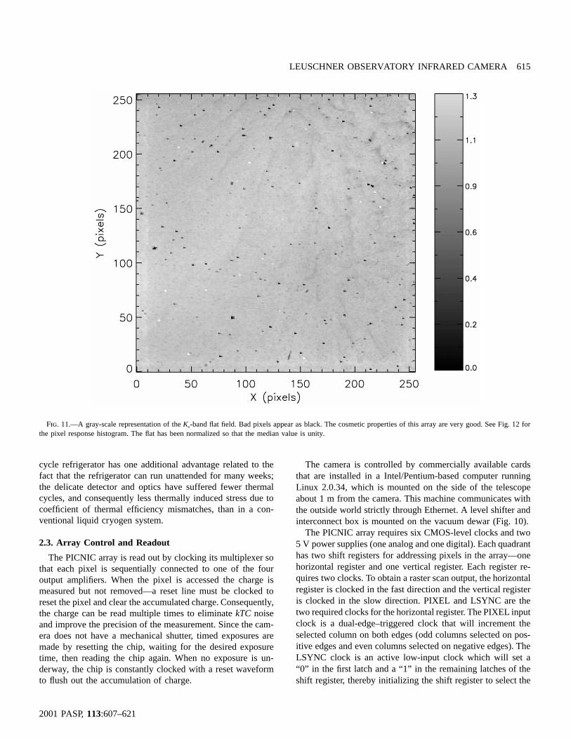
Fig. 11.—A gray-scale representation of the -band flat field. Bad pixels appear as black. The cosmetic properties of this array are very good. See Fig. 12 forKs
the pixel response histogram. The flat has been normalized so that the median value is unity.
cycle refrigerator has one additional advantage related to thefact that the refrigerator can run unattended for many weeks;the delicate detector and optics have suffered fewer thermalcycles, and consequently less thermally induced stress due tocoefficient of thermal efficiency mismatches, than in a con-ventional liquid cryogen system.
2.3. Array Control and Readout
The PICNIC array is read out by clocking its multiplexer sothat each pixel is sequentially connected to one of the fouroutput amplifiers. When the pixel is accessed the charge ismeasured but not removed—a reset line must be clocked toreset the pixel and clear the accumulated charge. Consequently,the charge can be read multiple times to eliminatekTC noiseand improve the precision of the measurement. Since the cam-era does not have a mechanical shutter, timed exposures aremade by resetting the chip, waiting for the desired exposuretime, then reading the chip again. When no exposure is un-derway, the chip is constantly clocked with a reset waveformto flush out the accumulation of charge.
The camera is controlled by commercially available cardsthat are installed in a Intel/Pentium-based computer runningLinux 2.0.34, which is mounted on the side of the telescopeabout 1 m from the camera. This machine communicates withthe outside world strictly through Ethernet. A level shifter andinterconnect box is mounted on the vacuum dewar (Fig. 10).
The PICNIC array requires six CMOS-level clocks and two5 V power supplies (one analog and one digital). Each quadranthas two shift registers for addressing pixels in the array—onehorizontal register and one vertical register. Each register re-quires two clocks. To obtain a raster scan output, the horizontalregister is clocked in the fast direction and the vertical registeris clocked in the slow direction. PIXEL and LSYNC are thetwo required clocks for the horizontal register. The PIXEL inputclock is a dual-edge–triggered clock that will increment theselected column on both edges (odd columns selected on pos-itive edges and even columns selected on negative edges). TheLSYNC clock is an active low-input clock which will set a“0” in the first latch and a “1” in the remaining latches of theshift register, thereby initializing the shift register to select the

616 GRAHAM & TREFFERS
2001 PASP,113:607–621
Fig. 12.—The histogram of the normalized pixel response of a -band flat.Ks
The rms of the best-fit Gaussian distribution is 0.04, and 3% of the pixels are“cold,” forming a tail with poor response.
first column in the quadrant. Since this is asynchronous to thePIXEL clock, LSYNC should be pulsed low prior to initiationof the first PIXEL clock edge. The horizontal register selectswhich column bus will be connected to the output amplifier.
These clock sequences are generated by an arbitrary wave-form generator card (PN PCIP-AWFG, Keithley Instruments).This card clocks out an 8 bit wide TTL-compatible word witha maximum pattern length of 32 K. These words are convertedto the 0–5 V levels suitable for driving the PICNIC readoutmultiplexer and reset lines by a high-speed CMOS buffer/linedriver (74HCT244). The four detector outputs (one for each
quadrant) pass through warm monolithic JFET-128# 128input operational amplifiers (PN LF356, National Semicon-ductor) with a gain of 5.1 and a manually adjustable offset, amonolithic sample and hold circuit (PN LF398, National Semi-conductor) to a 16 bit analog-to-digital converter card (PNDAS1602/16, Computerboards). The electronics interface boxis shown in Figure 10. This ADC has a 10ms conversion timeso the entire chip can be read in 660 ms. The data from thiscard pass through a very large FIFO (Mega Fifo, Computer-boards), so the data do not have to be read in real time.
The array controller supports several array operations:(1) read: reads chip with no reset; (2) reset: resets the chip butdoes not read; (3) frame: reset, expose, read; (4) correlateddouble sampling: resets and read, expose, read; (5) Fowlersampling: resets, read, expose, read. Here expose means waitthe requested duration. When a sequence involves two reads,the difference of the second minus first read is returned. Thisusually leads to a positive value of the signal.
2.3.1. Array Clocking Sequence Generation
Generating the clock waveforms for the PICNIC array iscentral to the entire operation. The key problem is generatingthe sequence of bytes that is to be downloaded into the AWFG
card. The six PICNIC clocks as well as the analog to digitalconverter trigger clock have been assigned to the two 4 bitoutputs of the AWFG. The AWFG is capable of storing awaveform of up to 32K steps long. When executing a waveformyou must specify the length of waveform, the number of timesto execute the waveform, and the clock divider specifying num-ber of microseconds per step.
Unfortunately, the maximum waveform length of 32K is notlarge enough to read out the entire PICNIC array. Instead, wemust specify a series of waveforms and execute them sequen-tially. The AWFG board does allow a new sequence to beloaded as the last sequence is finishing, if the length of thesequence is the same and the clock divider does not change.We have chosen a waveform of length of 4128 clock steps.
The basic step time is created from a 5 MHz clock dividedby 25, yielding a 5ms base step time. The full readout sequenceis created by stringing together multiple waveforms. Variousread modes are supported. For example, theread sequencewhich just reads through the entire chip and digitizes the resultis the combination of two waveforms. Theframe sequence ismore complex and is composed of three parts: (1) the chip isreset, (2) a variable length wait time (the exposure), and(3) theread sequence. The correlated double sampling is sim-ilar, except that the software subtracts the first values that areread just after the reset from the second reads after the exposureis done and reports the difference.
The software to control the camera was written in C�� fora client-server architecture. Linux device drivers for the threePC cards were written in-house. The camera server commu-nicates via TCP/IP sockets and has commands to read cameratemperatures and status, set readout waveforms, and read thePICNIC array.
The client program which is usually run on a remote machine(e.g., on a workstation in the Berkeley undergraduate lab) readsthe array and current telescope information and creates a FITSfile with data and detailed header. Since the observatory op-erations are automated, scripts can be written to combine imageacquisition and telescope motions. This is vital in infrared ob-servations where images are often built up from multiple joggedexposures.
The minimum readout time of 660 ms is determined by thespeed of the analog to digital converter card. Newer cards with1 ms conversion time are now available that would speed upthe read out time by a factor of 10 with little change in thesoftware.
3. PERFORMANCE
The camera operated successfully during the fall 2000semester, and sufficient observing time has been accumulatedby a class of 15 students to demonstrate satisfactory perform-ance. The design has proved reliable. For example, the Linux-based control software has never crashed. The only significantproblem was caused by the commercial helium compressor.

LEUSCHNER OBSERVATORY INFRARED CAMERA 617
2001 PASP,113:607–621
Fig. 13.—A single raw -band frame of NGC 2024. This is a 10 s exposure. Only the brightest stars ( mag) can be seen in this image. One pixelK K � 8s
corresponds to 1�.35, and the field of view is 5�. �.8.8 # 5
During early operation the model 21 CTI refrigerator deliveredmarginal cooling capacity, with the PICNIC array reaching only100 K. Initially, we suspected that the cold head was defectivesince it was a salvaged unit. However, the helium compressorfailed catastrophically after only a few thousand hours of op-eration; when it was replaced with a new unit the expectedcryogenic performance was achieved.
The adoption of a specially prepared motor for cryogenicoperation was a risk which allowed us to eliminate vacuumfeedthroughs. The stepper motor has worked flawlessly, andthis elegant solution for dewar mechanisms has paid off. Whenthe motor is driven continuously, or holding current is applied,sufficient heat is deposited within the dewar so that after severalhours of operation the temperature of the optics and the detectorrises by 10–15 K. In normal operation, where the filter wheelis active for a few seconds and then turned off, this heat sourceis insignificant. Application of holding current is unnecessarybecause the magnetic forces due to the permanent poles in themotor are sufficient to keep the filter wheel from moving.
Inspection of images delivered by the Offner relay at roomtemperature leads us to suspect that it is essentially perfect, butit has not proved possible to quantify the optical performance
because the image blur has been dominated by seeing andtelescope aberrations. These aberrations are due to telescopecollimation errors which are apparent in direct CCD images.The best image sizes delivered by the camera have size of lessthan 2 pixels FWHM (2�.6). However, this is achieved onlyafter careful focusing of the telescope secondary mirror.
In the next three subsections we describe several character-istics of the infrared array and the camera. Exploration andquantification of the camera performance forms the basis ofthe first lab performed by students. Once they have understoodthe operation of the camera and mastered the calibration ofimages, they are ready to make astronomical observations suchas the one outlined in § 3.4.
3.1. Array Uniformity
Under high-background conditions flat-field accuracy is themost important systematic error which limits sensitivity of anarray detector to faint sources. Modern arrays deliver veryuniform pixel-to-pixel response, which means that students caneasily construct a flat field that is adequate for all practicalpurposes. Even this array, which is nominally designated an

618 GRAHAM & TREFFERS
2001 PASP,113:607–621
Fig. 14.—Flat-fielding and sky subtraction of the raw frame in Fig. 13 reveal significantly more detail, including the low-contrast nebulosity. The coma andastigmatism apparent in this image are due to telescope collimation errors.
engineering-grade device, has excellent cosmetic characteristics(see Figs. 11 and 12). This is illustrated qualitatively by Figure11, which shows a gray-scale image of a -band flat field.Ks
This flat is a weighted mean of 11 dark-subtracted twilight skyimages. Taking twilight sky images requires careful timing: ifthey are taken too early the detector saturates; taken too latethen there is insufficient signal to form a high signal-to-noiseflat. For our pixel etendue ( cm2 sr) the optimum�71.6# 10time for taking -band images is between sunset or sunriseKs
and 6� twilight. A field at high Galactic latitude is suitable toavoid stars. The telescope is jogged between each exposure sothat stars occupy different pixels in subsequent pictures. Anypixels containing obvious stars are given zero weight, and theframes are combined into a weighted mean where outlyingpixels (faint stars or cosmic rays) are rejected if their deviationfrom the mean exceeds . In a flat normalized so that the3 j
median pixel value is 1.0, the best-fit Gaussian has an rms of0.04 (Fig. 12). Three percent of the pixels fall in a tail withlow response outside of this distribution, and the array can beconsidered 97% operable.
3.2. System Noise
Under the assumption that the variance in the camera signalis the sum of a constant read noise and Poisson fluctuations,it is straightforward to measure the read noise and gain. Thedata required for this measurement are a sequence of exposuresof increasing integration time while the camera views a sourceof spatially uniform illumination. A pair of exposures is ac-quired at each integration time. The mean signal level wasmeasured by subtracting a bias frame and the variance com-puted by differencing the two frames—since the uniformity offlat field is very high, the frames were not flat-fielded. Astraight-line, least-squares fit to the linear mean-variance re-lation yields the readout noise as the intercept and the gain asthe slope. The results of this analysis yield 30e� per datanumber (DN), and a read noise of 70e� rms. The majority ofthis is detector noise, since if one grounds the input to the dataacquisition system the variation is on the order of 30e� rms.A science-grade PICNIC array is expected to have a read noiseof about 10e� rms. Despite this elevated detector noise, the

LEUSCHNER OBSERVATORY INFRARED CAMERA 619
2001 PASP,113:607–621
Fig. 15.—The exposure mask for this observation. Seven good frames were acquired, each one at a different telescope pointing. This image represents theprojection of good pixels onto the field of view. Bad pixels can identified as local minima in the exposure mask. Dithering the telescope ensures that every pointin the field of view is covered by a functioning pixel.
data are background limited in all but the shortest exposures.The array saturates at 22,000 DN (660,000e�) and shows lessthan 1% nonlinearity at up to 80% of this level.
3.3. Throughput
The efficiency of the camera is expected to be high. Thedetector quantum efficiency is 60%–70% over most of the op-erating wavelength range. The average filter transmissions are86% (J), 83% (H), and 92% ( ) between the half-powerKs
points. The protected Al coating for the primary, , has anM1
infrared reflectivity of 97%, and the reflectivity of bare Al onthe secondary, , is probably similar. The quartz dewar win-M2
dow has a transmission of 94%, giving a predicted cameraefficiency of 50%. The system efficiency, including the tele-scope and atmosphere, determined from observation of stan-dard stars is 30% (J), 39% (H), and 44% ( ). The cameraKs
zero points in magnitudes on a Vega-based scale, defined as
�1m p m � 2.5 log (DN s ),zpt star 10
are 18.0 (J), 18.2 (H), and 17.5 ( ), where DN s�1 is theKs
count rate for a star of magnitude .mstar
3.4. An Example Observation
The region NGC 2024 (Orion B, W12) is a well-studied siteof massive star formation located at a distance of about415 pc (Anthony-Twarog 1982). It is also known as the FlameNebula, because of the shadow of prominent lanes of extinctionformed against a background of Ha emission from ionized gas.The ionizing stars for this nebula are hidden behind this dustlane. Near-infrared radiation from these stars penetrates the dustand a dense stellar cluster is revealed in the optically darkregion separating the two halves of the nebula. Observations

620 GRAHAM & TREFFERS
2001 PASP,113:607–621
Fig. 16.—The final -band mosaic for NGC 2024. The total exposure time in the center of the mosaic is 70 s. Heavy foreground extinction due to interstellarKs
dust reddens many of the stars in this cluster. Even at this wavelength, where the extinction is one-tenth of that at visible wavelengths, prominent dark dust lanesare apparent.
of NGC 2024 provide a dramatic demonstration of the abilityof near-infrared radiation to penetrate dust.
NGC 2024 was observed on 2000 November 4. Eight 10 sexposures were taken inJ, H, and . The telescope was ras-Ks
tered in a array (leaving out the central location) with3 # 3offsets of 36� in right ascension and declination between eachpointing. Exposures were collected inJ, H, and for the target,Ks
and then the telescope was offset to blank sky 6� to the eastand the filter sequence was repeated.
Figure 13 shows an individual -band image. Only theKs
brightest stars ( mag) can be seen in raw images. A sky-K � 8subtracted and flat-fielded image (Fig. 14) shows significantlymore detail, including the nebulosity. The exposure mask forthis observation is shown in Figure 15, and the final mosaiccomposed using a weighted sum of the registered imagesis shown in Figure 16. TheJ, H, and images have beenKs
registered and combined into a three-color composite. The op-tically invisible, highly reddened, stellar cluster behind the cen-tral dark lane stands out clearly (Fig. 17).
4. CONCLUSIONS
We have designed and built a high-performance near-infraredarray camera for the 30 inch telescope at Leuschner Obser-vatory. Our design eliminates custom parts in favor of com-mercial components. The array control and readout electronicsare composed entirely of standard PC cards. The only customboard is the interface which buffers the clocks from the wave-form generator and amplifies the analog signal from the detectoroutputs. The Offner-based optics relay the telescope image atunit magnification via a cold stop which provides effectivecontrol of thermal radiation from the telescope and its envi-ronment. The camera has been used successfully in an under-graduate laboratory class in fall 2000.
Construction of this camera was made possible by theNational Science Foundation through Instructional LaboratoryInitiative grant 9650176 and the generous support of KadriVural at the Rockwell Science Center, Thousand Oaks, Cali-

LEUSCHNER OBSERVATORY INFRARED CAMERA 621
2001 PASP,113:607–621
Fig. 17.—A three-color infrared image of NGC 2024. Red corresponds to , green isH, and blue isJ. The reddened stars at the center of the image areKs
responsible for ionizing the gas in this region. The mosaic has been cropped to a field of view of 5�. �.8. The exposure time is 80 s per filter, and the limiting8 # 5magnitude is 14.2 atJ and 13 at . North and east are indicated.Ks
fornia. The Berkeley Astronomy Department provided match-ing funds for this enterprise. We thank Professor I. S. McLean(University of California, Los Angeles) for advice during thedesign and construction of the camera. W. T. Lum and Dr.
D. Williams of Berkshire Technologies helped with the dewar,and C. Chang (University of California, Berkeley, Radio As-tronomy Lab) did the PC layout. Professor C. Heiles providedinvaluable guidance and encouragement.
REFERENCES
Anthony-Twarog, B. J. 1982, AJ, 87, 1213McLean, I. S., et al. 1994, Proc. SPIE, 2198, 457Murphy, D. C., Persson, S. E., Pahre, M. A., Sivaramakrishnan, A.,
& Djorgovski, S. G. 1995, PASP, 107, 1234Nelson, B., McLean, I. S., Henriquez, F., & Magnone, N. 1997, PASP,
109, 600Offner, A. 1975, Opt. Eng., 14, 130
Parthasarathy, R., Frank, C., Treffers, R., Cudaback, D., Heiles, C.,Hancox, C., Millan, R. 1998 Am. J. Phys., 66, 768
Treffers, R. R., Richmond, M. W., & Filippenko, A. V. 1992, in ASPConf. Ser. 34, Robotic Telescopes in the 1990s, ed. A. V. Filippenko(San Francisco: ASP), 115
Vural, K., et al. 1999, Proc. SPIE, 3698, 24