An experimental study on the performance of … DVD/Foundations and...KEYWORDS: Bearing capacity,...
7
3 r d International Conference on New Developments in Soil Mechanics and Geotechnical Engineering, 28–30 June 2012, Near East University, Nicosia, North Cyprus 297 KEYWORDS: Bearing capacity, eccentric loading, reinforced soil, footings ABSTRACT: An experimental program, which is composed of a series of laboratory model loading tests on 100 mm wide (B) square footings under eccentric loading on cohesionless soils reinforced with unsymmetrically placed layers of geogrid, was carried out. A total of ten tests with a loading eccentricity (e L ) of e L / B = 0.05 were conducted on both unreinforced and geogrid-reinforced sand. One to three geogrid layers were placed with different lengths to achieve a geogrid eccentricity (e G ) of 5, 205, and 230 mm. The bearing capacity improvement of the footings on the reinforced sand is quantified using the dimensionless bearing capacity factor (BCR). Based on the results of the loading tests, recommendations were made for the required length of the nonsymmetrically placed geogrids as a function of the number of reinforcing layers. 1 INTRODUCTION Parallel to the significant increase in the employment of geosynthetics as soil reinforcement under foundations during the last few decades, the behavior of reinforced soil foundations has been thoroughly examined considering various construction parameters and performance requirements (e.g., Das 2009). These parameters include, but are not limited to, the number of reinforcing layers, the depth, spacing, length and stiffness of the reinforcement and the soil type, as well as the depth and shape of the foundation. The results of the experimental studies in the literature showed that, in general, the use of reinforcements, especially geogrids, can significantly increase the bearing capacity and reduce the settlement of foundations. However, it has also been noticed that better improvements in the performance of the foundation systems are obtained when they are designed using certain combinations of the above mentioned parameters. Only a few studies have focused on the behaviour of eccentrically loaded footings supported on reinforced sand (e.g., Shin & Das 2000). In addition, most of the available literature that deals with the behaviour of eccentrically loaded footings on reinforced soil involves model test results of strip foundations that are supported on soil in which geogrid layers are placed symmetrically. However, very scarce data is available on the load-settlement response of eccentrically loaded rectangular footings on unsymmetrically placed reinforcing layers. The only study that considers both geogrid placement and load eccentricities that the authors are aware of is that of El Sawwaf (2009). Using the results of model tests conducted on 75 mm wide eccentrically loaded strip footings on cohesionless soil reinforced with one to four layers of geogrid that are placed eccentrically, El Sawwaf (2009) An experimental study on the performance of eccentrically loaded footings on cohesionless soil reinforced with nonsymmetrical geogrid layers A. C. Gel Research Assistant, Gazi University, Ankara, Turkey, [email protected] S. O. Akbas Assoc. Prof. Dr., Gazi University, Ankara, Turkey, [email protected] O. Anil Assoc. Prof. Dr., Gazi University, Ankara, Turkey, [email protected]
Transcript of An experimental study on the performance of … DVD/Foundations and...KEYWORDS: Bearing capacity,...

3rd International Conference on New Developments in Soil Mechanics and Geotechnical Engineering,
28–30 June 2012, Near East University, Nicosia, North Cyprus
297
KEYWORDS: Bearing capacity, eccentric loading, reinforced soil, footings
ABSTRACT: An experimental program, which is composed of a series of laboratory model loading
tests on 100 mm wide (B) square footings under eccentric loading on cohesionless soils reinforced
with unsymmetrically placed layers of geogrid, was carried out. A total of ten tests with a loading
eccentricity (eL) of eL / B = 0.05 were conducted on both unreinforced and geogrid-reinforced sand.
One to three geogrid layers were placed with different lengths to achieve a geogrid eccentricity (eG)
of 5, 205, and 230 mm. The bearing capacity improvement of the footings on the reinforced sand is
quantified using the dimensionless bearing capacity factor (BCR). Based on the results of the
loading tests, recommendations were made for the required length of the nonsymmetrically placed
geogrids as a function of the number of reinforcing layers.
1 INTRODUCTION
Parallel to the significant increase in the employment of geosynthetics as soil reinforcement under
foundations during the last few decades, the behavior of reinforced soil foundations has been
thoroughly examined considering various construction parameters and performance requirements
(e.g., Das 2009). These parameters include, but are not limited to, the number of reinforcing layers,
the depth, spacing, length and stiffness of the reinforcement and the soil type, as well as the depth
and shape of the foundation. The results of the experimental studies in the literature showed that, in
general, the use of reinforcements, especially geogrids, can significantly increase the bearing
capacity and reduce the settlement of foundations. However, it has also been noticed that better
improvements in the performance of the foundation systems are obtained when they are designed
using certain combinations of the above mentioned parameters.
Only a few studies have focused on the behaviour of eccentrically loaded footings supported on
reinforced sand (e.g., Shin & Das 2000). In addition, most of the available literature that deals with
the behaviour of eccentrically loaded footings on reinforced soil involves model test results of strip
foundations that are supported on soil in which geogrid layers are placed symmetrically. However,
very scarce data is available on the load-settlement response of eccentrically loaded rectangular
footings on unsymmetrically placed reinforcing layers. The only study that considers both geogrid
placement and load eccentricities that the authors are aware of is that of El Sawwaf (2009). Using the
results of model tests conducted on 75 mm wide eccentrically loaded strip footings on cohesionless
soil reinforced with one to four layers of geogrid that are placed eccentrically, El Sawwaf (2009)
An experimental study on the performance of eccentrically loaded footings on cohesionless soil reinforced with nonsymmetrical geogrid layers
A. C. Gel
Research Assistant, Gazi University, Ankara, Turkey, [email protected]
S. O. Akbas
Assoc. Prof. Dr., Gazi University, Ankara, Turkey, [email protected]
O. Anil
Assoc. Prof. Dr., Gazi University, Ankara, Turkey, [email protected]

3rd International Conference on New Developments in Soil Mechanics and Geotechnical Engineering,
28-30 June 2012, Near East University, Nicosia, North Cyprus
298
concluded that the footing response much improves as distance between the action line of the load to
the centre of the geogrid layer length (eG) decreases.
Considering these points, the main aim of this research is to contribute to the understanding of
the behaviour of eccentrically loaded square footings on cohesionless soils reinforced with geogrid
layers that are placed in an unsymmetrical manner. To achieve this objective, a series of laboratory
loading tests on 100 mm wide rectangular model footings under a load eccentricity of 5 mm were
conducted. The soil supporting the model footings was reinforced with varying numbers of geogrid
layers that were placed unsymmetrically.
2 LABORATORY MODEL TEST SETUP
The experimental model tests were conducted in steel test box, two sides of which are made of 20
mm thick glass, having internal dimensions of 1.00 m x 0.50 m in plan and 0.40 m in depth (Figure
1). The loading system was mounted on two horizontal U steel beams supported by two steel
columns. It consists of a hand-operated hydraulic jack and pre-calibrated load ring.
Figure 1. A photo of the test setup for model-scale footing tests
The sand (USCS classification SW) that was used in the tests was characterized through its specific
gravity, maximum and minimum densities, and grain size distribution. The specific density (Gs) of
the soil particles as determined by the gas jar method resulted in an average value of 2.71. The
maximum and minimum densities of the sand were determined to be 1.88 and 1.49 Mg/m3, with
corresponding values of the minimum and maximum void ratios of 0.44 and 0.81. The particle size
distribution was determined using the dry sieving method and the results are shown in Figure 2. The
effective size (D10), the uniformity coefficient (Cu), and coefficient of curvature (Cc) for the sand
were determined as 0.12, 7.50 and 1.00, respectively.
An experimental study on the perf. of eccentrically-loaded footings on cohesionless soil reinforced w. nonsymmetrical geogrid layers Gel, A.C., Akbas S.O. & Anil O.
299
Figure 2. Grain size distribution of the sand
Direct shear tests that were performed on sand samples with a relative density (Dr) of 55% resulted
in an effective stress friction angle of 35.6o. Note that the normal stresses used to determine this
friction angle ranged from 95 to 500 kPa. All loading tests were performed in dry conditions, i.e.
using oven-dried sand, with the footing resting on the sand surface (Figure 1). Model-scale square
steel footings with artificially roughened bases having widths of 0.10 m with 20 mm thickness were
eccentrically loaded in this study. The sand was hand compacted in 0.05 m lifts with a steel tamper
to a unit weight of 1.68 Mg /m3 (Dr = 55%). For each test, a fresh test bed of sand was prepared.
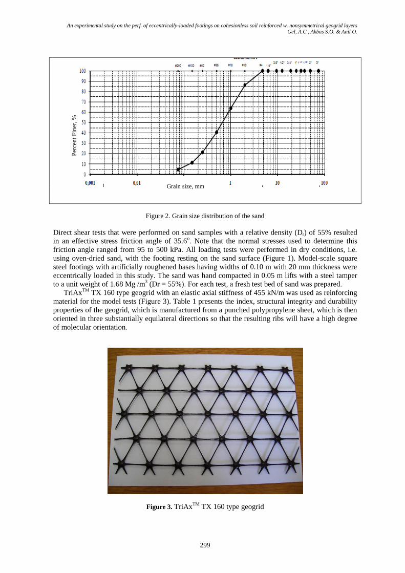
TriAxTM
TX 160 type geogrid with an elastic axial stiffness of 455 kN/m was used as reinforcing
material for the model tests (Figure 3). Table 1 presents the index, structural integrity and durability
properties of the geogrid, which is manufactured from a punched polypropylene sheet, which is then
oriented in three substantially equilateral directions so that the resulting ribs will have a high degree
of molecular orientation.
Figure 3. TriAxTM
TX 160 type geogrid
Grain size, mm
Per
cen
t F
iner
, %

3rd International Conference on New Developments in Soil Mechanics and Geotechnical Engineering,
28-30 June 2012, Near East University, Nicosia, North Cyprus
300
3 LABORATORY MODEL TEST RESULTS
An experimental programme was carried out to study the behaviour of eccentrically loaded model
square surficial footings resting on sand reinforced with one to three layers of unsymmetrically
placed geogrid. For all of the load tests, the load eccentricity was maintained to be 5 mm. The
geogrid layer lengths were varied to be 550, 600 and 1000 mm, which resulted in eG values of 230,
205 and 5 mm, respectively. Model soil samples with a height of 400 mm were prepared at 50 mm
layers to achieve a constant and uniform relative density. On reaching each reinforcement level, the
upper most of which is located at a depth of 37.5 mm from the surface, the geogrid layer was placed
and the remaining soil thickness was poured and tamped. Note that, when present, the second and the
third geogrid layers were placed at depths of 87.5 mm and 137.5 mm from the surface, respectively.
New sheets of reinforcement were used for each test. Finally, the footing was placed in position and
the load was applied on it through the hydraulic jack in small increments until reaching failure or the
limiting displacement. Each load increment was maintained as constant until the footing settlement
had stabilized. The settlement of the footings was measured using two LVDT (linear variable
differential transformer) displacement transducers located at two corners.
The test setup is depicted in Figure 4, showing all of the above mentioned parameters. eG and eL
parameters are shown in Figure 5 for 550 mm geogrid length.
Table 1. Engineering properties of geogrid
Property Longitudinal Diagonal Transverse General
Rib Pitch (mm) 40 40 -
Mid-rib Depth (mm) - 1.8 1.5
Mid-rib Width (mm) 1.1 1.3
Nodal Thickness (mm) 3.1
Rib Shape Rectangular
Aperture Shape Triangular
Junction Efficiency (%) 93
Radial Stiffness at Low Strain (kN/m) 300
Axial Stiffness (kN/m) 455
Ten tests on axially loaded square footings supported on both unreinforced and geogrid-reinforced
sand were carried out. In this study, the ultimate capacity (qult) was interpreted as the bearing stress,
which produced a fixed relative settlement: 10% and 50%B (i.e., for 10%B, the settlement(s) / B =
0.1 = 10 mm for B = 100 mm). As indicated by Cerato and Lutenegger (2006), although choosing to
define qult at a relative settlement of s / B is completely arbitrary, it (1) is convenient and easy to
remember, (2) is close to the average soil strain at failure for 10%B, (3) forces a fixed value at qult,
and (4) treats displacement of different footing sizes the same.
The results for the model footing tests in terms of ultimate loads and bearing capacity ratio
(BCR) values are summarized in Table 2. Note that the BCR value is defined as the ratio of the
bearing capacity of a given test to the bearing capacity obtained for the load test with unreinforced,
i.e., without geogrid, soil. The obtained load–settlement curves for the model footing tests performed
using a single geogrid layer along with the unreinforced case are presented in Figure 6. In addition,
Figure 7 presents the variation of BCR with geogrid length and number of layers as a function of
failure load definition.

An experimental study on the perf. of eccentrically-loaded footings on cohesionless soil reinforced w. nonsymmetrical geogrid layers Gel, A.C., Akbas S.O. & Anil O.
301
Figure 4. A schematic view of the test setup (Not to scale)
Figure 5. parameters eG and eL for 550 mm geogrid length
Table 2. Summary of model loading test results
Spec.
No
Geogrid Layer
Number
Geogrid
Length (mm)
Ultimate Load (kN) BCR
at 50 mm
Disp.
at 10 mm
Disp.
at 50 mm
Disp.
at 10 mm
Disp.
1 Without Geogrid ----- 0.80 0.64 - -
2
One
1000 2.42 0.91 3.03 1.42
3 600 1.21 0.61 1.51 0.95
4 550 0.46 0.46 0.58 0.71
5
Two
1000 4.40 0.76 5.50 1.18
6 600 2.58 0.76 3.23 1.18
7 550 1.21 0.61 1.51 0.95
8
Three
1000 6.21 0.91 7.76 1.42
9 600 3.64 1.06 4.55 1.66
10 550 1.67 0.76 2.09 1.18
Tank Length=1000 mm
Tank Width =500 m
m
Tank Height=400 mm
100
100
P5 mm
137.587.5
37.5
Geogrid Length = 550, 600, 1000 mm
eL=5
L=550
500
Center of Tank
Center of Geogrid
275225
eG=230
Soil

3rd International Conference on New Developments in Soil Mechanics and Geotechnical Engineering,
28-30 June 2012, Near East University, Nicosia, North Cyprus
302
Figure 6. Load–settlement relationship for footings with no (Specimen 1) or a single layer of reinforcement
Figure 7. The variation of BCR with geogrid length and number of layers as a function of failure load
definition
4 DISCUSSION OF RESULTS
The ratio of BCR values obtained using different configurations of geogrid placement length, i.e.,
geogrid eccentricity, varying number of geogrid layers and different means of defining the failure
load, spans a very wide range of about 0.60 and 7.80. Note that this wide range of BCR values are
obtained for a footing of fixed size, loaded identically on sand with a fixed relative density. Thus, the
effects of the above mentioned parameters on the footing performance are quite significant without
any doubt.
The results obtained from the series of model load tests indicate that, as expected, increasing the
number of geogrid layers from one to three has a positive effect on the bearing capacity in general.
This effect is more pronounced when the failure load is defined to be the load obtained at 50 mm of
displacement. For this case, the increase in the BCR by changing the number of layers from one to
two is always higher than that obtained by changing the layer number from two to three. This
indicates that the enhancement in the bearing capacity due to the increased number of geogrid layers
has a limit, which is commonly quoted to be three layers optimally in the literature. For the cases
0
0.5
1
1.5
2
2.5
3
3.5
4
0 10 20 30 40 50 60 70 80
Average Settlement (mm)
Lo
ad
(k
N)
Specimen-1 Specimen-2
Specimen-3 Specimen-4
Specimen-3
Specimen-2
Specimen-1
Specimen-4
0
1
2
3
4
5
6
7
1 Layer 2 Layers 3 Layers 1 Layer 2 Layers 3 Layers
Failure Load @50%B Failure Load @10%B
BC
R
GeogridLength (mm):
1000
600
550

An experimental study on the perf. of eccentrically-loaded footings on cohesionless soil reinforced w. nonsymmetrical geogrid layers Gel, A.C., Akbas S.O. & Anil O.
303
where the failure load is determined at 10%B deformation, the increase in the bearing capacity due to
increased layer number cannot be observed clearly. This observation points out the fact that, in order
for the geogrid layers’ positive reinforcing effects to be observed, a significant amount of footing
deformation should occur.
The results also indicate that the geogrid placement eccentricity has a significant effect on the
resulting footing performance. For a geogrid layer length of 1000 mm, which corresponds to an eG
value of 5 mm only, the BCR values are always greater than one, i.e., a reinforcement effect is
available, without regard to the number of layers. However, as mentioned above, the obtained BCR
is very much dependent on the way the failure load is defined. Compared to 1000 mm geogrid
length, increasing the value of eG to 205 mm, which corresponds to a geogrid length of 600 mm
resulted in significant decreases in the BCR values that range between 41 and 50% for failure load
defined at 50%B. A further decrease in BCR that ranges between 72 and 80% was observed for the
same failure criterion when eG was raised to 230 mm. Note that no reinforcing effect could be
obtained for a single layer of geogrid at 10%B deformation when its length was 550 or 600 mm. For
the same failure criterion, even two layers of reinforcement failed to improve the performance when
the lengths were limited to 550 mm.
5 CONCLUSIONS
The results of a series of laboratory loading tests on eccentrically-loaded model square footings
supported by unsymmetrical layers of geogrid-reinforced sand are presented. The following main
conclusions are reached:
1. For unsymmetrically loaded geogrid layers, the placement length has a significant influence
on the BCR values. The results obtained in this study indicate that a geogrid layer extending
up only to the footing edge does not have the reinforcing effect unless three layers of it is
available.
2. It is observed that the enhancement in the bearing capacity due to an increased number of
geogrid layers has a limit for eccentrically-loaded square footings also. According to the
limited number of test results, the optimum number of layers seems to be three, although
further studies are required.
3. All of the obtained results depend on the criterion that is used to define failure. It is noted
that the reinforcing effect of geogrid layers for eccentric placement and loading is mostly
available after a certain deformation level.
REFERENCES
Das, B.M. & Atalar, C. (2009) Developments on the bearing capacity of shallow foundations on geogrid-reinforced soil-A review, proceedings of the 3rd Geotechnic Symposium, 3-4 December 2009, Adana, Turkey, 1-42
El Sawwaf, M. (2009). Experimental and numerical study of eccentrically loaded strip footings resting on reinforced sand. Journal of Geotechnical and Geoenvironmental Engineering, 135(10): 1509–1518.
Shin, E.C. & Das, B.M. (2000). Experimental study of bearing capacity of a strip foundation on geogrid-reinforced sand. Geosynthetics International, 7(1): 59–71.