Experimental studies on active and passive solar stills in ...

An experimental study of passive dynamic walkingQ. Wu and N. SabetDepartment of Mechanical and Industrial Engineering, The University of Manitoba, Winnipeg, Manitoba (Canada)R3T 5V6
(Received in Final Form: August 30, 2003)
SUMMARYA two-straight-legged walking mechanism with flat feet isdesigned and built to study the passive dynamic gait. It isshown that the mechanism having flat feet can exhibitpassive dynamic walking as those with curved feet, but thewalking efficiency is significantly lower. It is also shownthat the balancing mass and its orientation are etfective forcontrolling side-to-side rocking and yaw, which havesignificant effects on steady walking. The effects of variousparameters on the gait patterns are also studied. lt is shownthat changes in the ramp angle have the most dominanteffect on the gait pattern as compared with the changes inthe hip mass, ramp surface friction and size of the flat feet.More specifically, as the ramp angle increases, the steplength increases while the range of the side-to side rockingangle decreases and the step length dictates the walkingspeed and the gravitational power Another finding, is thatadding a hip mass improves the walking efficiency byallowing the mechanism to walk on a flatter ramp. Thisresearch enables us to gain a better understanding of themechanics of walking. Such an understanding will have adirect impact on better design of prostheses and on theactive control aspects of bipedal robots.
KEYWORDS: Biped; Passive dynamic walking; Gait pattern.
1. INTRODUCTIONDevelopment of bipedal walking machines has attractedlong-time interests. The most common approach is tocontrol joint angles to mimic the walking of animals orhumans. The disadvantages of this trajectory-controlapproach include its inefficiency in actuating the bipedalwalking and the unnatural looking of the gait. One exampleis the Honda P3 robot, which weighs 130 kg and usesapproximately 2 kW power during walking, more than 20times the muscle work rate of a walking human of the samesize,1 yet the gait pattern is not natural. Some of the energycost is due to friction and the impact where the swing footcomes in contact with the ground. However, the majorportion of this energy consumption is the consequence ofthe trajectory-based approach, especially when the desiredjoint angle profiles are designed without the considerationof energy efficiency. One fundamental problem in theresearch using the trajectory-control approach is that theimportance of the control actuation is over-emphasized, butthe role of the mechanic/dynamics of the respective bipedalsystem is overlooked.
A parsimonious approach to the studies of the mechanicsof bipedal gait is to study the passive dynamic walking.McGeer2 demonstrated through simulations and experi-ments, that there exists a class of two-legged mechanismsfor which walking is a natural dynamic mode. Once startedon a shallow slope, these mechanisms will settle into asteady gait quite comparable to human walking without anyactive control or energy input. Collins et al.,1 Coleman andRuina,3 Garcia et al.,4,5 Kuo6 and Chatterjee and Garcia7
confirmed McGeer’s finding, and further extended theresearch using two approaches. One is to build variousphysical mechanisms to demonstrate the existence ofpassive dynamic walking. For example, Coleman andRuina3 built a simple two-leg toy that is statically unstablein all standing positions, yet is stable in walking down ashallow slope. Collins et al.1 built the first three-dimen-sional, two-legged and kneed passive-dynamic walkingmachine. Their machine not only preserved features ofMcGeer’s two-dimensional model, including mechanicalsimplicity, humanlike knee flex, and passive gravitationalpower from descending a shallow slope, but also addedspecially curved feet, a compliant heel and mechanicallyconstrained arms to achieve a harmonious and stable gait.One common feature of the above walking mechanisms isthat all the feet are either semicircular or curved. In spite ofthe improvement of the energy efficiency, the reason ofusing semicircular or curved feet is that passive walking hasbeen inspired by the observations of smooth rolling ofwheels along a level surface. However, as correctly pointedout by McGeer2, the semicircular foot was a mathematicalconvenience rather than a physical necessity. He speculatedthat other arrangements, such as a flat foot, should befeasible for a similar passive gait.
The computer simulation method has mainly been used tostudy the stability and the performance of various passivedynamic walking machines. McGeer2 studied the effects ofparameter variations on the step period and the step length.The varied parameters included the foot radius, hip mass,hip damping, leg inertia, height of the mass center and legmismatch. Garcia et al.4 used an irreducible simple,uncontrolled, two-dimensional and two-link model to studythe stable passive dynamic gait. They found two distinct gaitpatterns at small ramp angles, of which the longer-step gaitis stable at small slopes. They also found that, by increasingthe ramp angle, stable cycles of higher periods appear, andthe walking-like motion apparently becomes chaoticthrough a sequence of period doublings. Kuo6 extended theplanar motions to allow tilting side to side (rocking motion)
Robotica (2004) volume 22, pp. 251–262. © 2004 Cambridge University PressDOI: 10.1017/S0263574703005563 Printed in the United Kingdom

and found that passive walking cycles exist, but the rockingmotion is unstable. Kuo could not find passive strategies tostabilise the rocking motion. Chatterjee and Garcia7 studiedthe passive dynamic walking using the simulation method.They found that small slopes preclude long steps and thatsmall steps imply low speeds. These investigations providedimportant insights into the mechanics of bipedal walking. Inaddition, the computer simulation approach enables one toconduct simulations that are difficult even impossible forphysical experiments.
The previous research on passive dynamic walking isintriguing. The results suggest that the mechanical parame-ters of the biped (e.g. link lengths, mass distributions) havea greater effect on the existence and the quality of gait thanis generally recognised. Thus, one needs to also studymechanics, not just activation and control, to fully under-stand walking.1,2,6 In the course of this research, the authorsnoticed that most of the findings related to the parametriceffects on the passive dynamic gait patterns have beenobtained using simplified computer models where semi-circular feet or point feet were used, while the physicalmodels, all with curved feet, have been restricted to thedemonstration of the existence of the passive dynamicwalking. Limited experimental results of the effects ofparameters on the passive gait pattern has only beenreported by McGee,2 where only the changes in the rampangle and the leg mass center offset were considered.Computer modelling is a powerful method. However, theonly study that intended to compare the simulations withthe experimental results has shown poor match between thetwo.2
In this paper, we present the design and the constructionof a two-straight-legged passive dynamic walker similar tothe one described by McGeer2 except that flat feet are usedinstead of semicircular or curved feet. Thus, the passivewalker reported here can stand still. We further study, using
the developed walking device, the effects of parametervariations on the gait patterns. These parameters are theramp angle, ramp surface friction, hip mass and size of theflat feet. The gait patterns to be compared are: step lengths,step periods, walking speeds, the gravitational power andranges of side-to-side rocking angles. The overall objectiveof this work is to gain better understandings of themechanics of passive dynamic walking. Understandings ofthe mechanics and the limits imposed by passive dynamicwalking will allow us to better design prostheses. They willalso have a direct impact on the active control aspects ofwalking because good controllers take advantages of thenatural dynamics of their respective systems. Once passivedynamic walking is better understood, simple controlmechanisms with small amounts of power can be introducedto increase the stability of the motion.1
The paper is organised as follows: The design of thepassive walker is presented in Section 2. The measurementprocedure, including the equipment set up, data acquisitionand data analysis are also detailed in the same section. Theresults and their indications are discussed in Section 3,followed by concluding remarks in Section 4.
2. METHODOLOGY
2.1. Design and construction of the walking mechanismThe walking device, as shown in Figure 1, weighs 187.5grams and stands 21 cm. It consists of two legs withrectangular plastic feet and two arms extending out from thefeet with a balancing mass at each end. The followingmaterials were used to build the walking mechanism: aTinkertoy Classic Junior Builder Set of which all the piecesare made of wood, two pieces of 0.9 cm thick plexi glass(used as feet), two blocks (2.7 cm� 3.3 cm� 4.9 cm) ofwood (used as hinges) and wooden balancing masses, whichconsist of one arm (15.4 cm), one spool (5 cm_diame-
Fig. 1. Picture of the passive dynamic walker.
Passive walking252

ter� 1.7 cm_thickness), one rod (5 cm) and threerectangular wood (4.6 cm�
3.7 cm� 0.7 cm). The orientation of the balancing mass canbe adjusted by rotating the rod about the arm (see Figure 1for details).
The two legs were connected to each other at the top ofthe walker with a pin joint type of mechanism. The twowooden blocks had a hole drilled through them slightlylarger than the size of the wooden pin that passed throughboth blocks. The size of the hole was modified until itreached to a size with minimum friction. All legs and armswere approximately 90° from each other except thebalancing mass assembly, where the rod was tilted approx-imately 25° to 35° angle from the upright direction oppositeto the walking direction.
The most challenging part of the assembly is the pin jointat the hip of the walker. It is extremely important that thelegs remain perpendicular to the walking surface. For thisreason, the joint was required to be both tight enough not toallow any caving of the leg in the frontal plane and alsoloose enough to allow the pin moving freely in the woodenblocks, which have been made as a pin joint. Many minorrefinements were required until the walker met bothconditions. All the pieces fit quite tightly together and didnot require the use of glue except the plexi glass feet thatwere glued to the wooden leg spools of the walker.
2.2. Measurement protocolThe method for measuring gait parameters of the walkingdevice is presented in this section. The protocol includes theequipment setup, measurement procedure and data process-ing. Two camcorders (Samsung SCL310 (NTSC) andCannon XL1 (NTSC)) were used to record the trials as thepassive device walking down the ramp simultaneously. Onewas facing the frontal plane and another one was facing thesagittal plane. A ruler was set at the center of themeasurement field for calibration. The detailed set up isshown in Figure 2.
In each trial, our tested biped was started by hand fromthe top of a ramp, and after a few steps, it settled into thesteady gait appropriate for the slope in use. It is important tonote that for each trial the walker undergoes a period knownas the transient stage where the gait pattern is not steady. It
is up to the operators’ discretion as to where this transientstage ends. The video, recording the motion in both sagittaland frontal planes, was then digitised frame by frame. Onceall the useful data were extracted, they were inputted intoexcel spreadsheets where the step length, step period, slopespeed and gravitational power were determined as follows:
Step length: To calculate the step length, the distance wasmeasured in which the walker took a given number of steps.This distance was then divided by the number of steps takento obtain the average step length. With the existingequipment we believe that this method of calculation wouldresult in a lower measurement error than directly measuringeach individual step.
Step period: The calculation of the step period is similar tothat of the step length. With the camcorders having thefrequency of 30 frames per second, the time was noted whenthe foot was leaving the ramp surface at the first steady step.Once the walker had walked a certain distance, the foottouched the ramp surface and the time at this point wasrecorded. The difference between the time instants was thendivided by the number of steps taken to obtain the averagestep period.
Gravitational power: Gravitational power has been definedas the rate of work produced by the gravity during passivewalking4. It can be expressed as mgV sin �, where V is thewalking speed along the ramp, m is the total mass, g is thegravitational acceleration and � is the ramp angle.
Walking efficiency: The passive walking efficiency has been
defined as mechanical work
weight� distance traveled
3,5
. For gravity-powered
walking, the efficiency is measured by the walking slope,sin �, where � is the ramp angle.
The measurements and data analyses were conductedover all data except those from the first few steps in thetransient stage of each trial. For each parameter variation,the experiment was repeated for six trials. All the abovevariables from six trials were averaged and standarddeviations were calculated.
3. RESULTS AND DISCUSSIONSIn this section, we present and discuss the experimentalresults. The objective is to gain an understanding of themechanics of bipedal walking.
3.1. ObservationsSteady walking was observed from our passive walker. Weplaced the walker at the top of the ramp faced downhill,tipped the walker to one side and then released it. Thewalking device rocked side to side, coupled with swingingof the legs and took tiny steps downward the ramp. Whenthe swing foot collided with the ground, support would betransferred impulsively from the heel to the toe at themidstance. We were able to achieve a 70% to 80%successful rate of launches. Our best ramp angle is 4°. Afterseveral trials, we reached to 90% successful rate or higher,and the walker seemed more robust in that it was lesssensitive to the initial disturbance and it reached to steadyFig. 2. Experimental set-up.
Passive walking 253

walking faster as compared with other ramp angles. Theabove observations confirmed that a two-legged mechanismwith flat feet can exhibit passive dynamic walking like thosewith semicircular or curved feet. The observed humanlikewalking is dictated by the combination of system parame-ters as its counterpart with curved feet.
Two interesting observations about side-to-side rockingand yaw (rotation about the vertical axis) have been made.Side-to-side rocking provides the ground clearance, whichis essential for walking with straight legs. Kuo6 showed,through computer simulations, that unconstrained side-to-side rocking can lead to instability, but he could not find apassive strategy for stabilization. Kuo’s simulation model6 issimilar to our walker without balancing masses. Side-to-side rocking is actuated by the moment resulted from thegravity of the walker about the axis parallel to the walkingdirection and passing the supporting foot during the singlesupport phase. Since the gravity center is not always on topof such an axis, the tendency of side-to-side rocking alwaysexists, which must be counteracted. In our experiment, wewere unable to achieve steady walking without balancingmasses. By closely observing the walking motion, wenoticed that a number of tipping-over were due to the rapidincrease in rocking angles within a short period of time. Thelarge rocking angle often caused the walker to tip over toeither side. By adding proper balancing masses, weincreased the moment of inertia, i.e., the resistance torocking, and we were able to manipulate the frequency andthe magnitude of side-to-side rocking, which were phase-locked with the swinging motion leading to steady walking.Thus, our assembly of balancing masses can be used as asimple passive strategy for stabilizing side-to-side rocking.Another technique to resist rocking is to use swing arms.For example, Collins et al.1 used two arms to swing freelylaterally to enhance the side-to-side rocking stability andWisse et al.8 suggested a free-side-to-side-swinging mass tobalance rocking of the walker. Regardless the techniques,side-to-side rocking is needed for bipedal walking, but itmust be controlled carefully. The balancing mass assemblyis a simple yet effective passive tool for controlling side-to-side rocking.
It is not surprising that as one leg moves forward, yawwill be generated. This is because as one leg moves forward,the two side-by-side legs will have angular momentumvariations about the vertical axis, which induces yaw. Thus,yaw is inherent to bipedal walking, and it is highlyundesirable. Our initial trials showed that even if small yawwas present, the walker fell quickly. Thus, the effects of yawmust be counteracted. In our experiment, we found that yawis sensitive to the orientation of the balancing mass, and tohave steady walking possible, the rod of the balancing massmust be tilted in the opposite direction of walking. For theramp angle of 4°, the optimal orientation of the balancingmass is about 27° from the vertical in the opposite directionof walking, which can almost eliminate yaw effects in ourwalking device. Thus, the balancing mass and its orientationcan be a possible passive control of yaw. Another way toreduce yaw is to use swing arms. For example, in theprevious work /two arms were constrained to move fore andaft with the opposite leg to increase the resistance to yaw.
In the course of reducing yaw, we noticed that thedynamic effects from swinging, side-to-side rocking andyaw are highly coupled. The acceptable orientation of thebalancing mass for counteracting yaw is sensitive to thefrequencies and the magnitudes of side-to-side rocking, aswell as swinging. The highly interactive dynamic effectsfrom the above three motions make the understanding ofpassive dynamic walking challenging.
In summary, we observed steady walking in our straight-legged mechanism with flat feet. Although the dominantswinging motion occurs in the sagittal plane, side-to-siderocking and yaw are inherent to the side-by-side bipedalwalking and they have significant effects on the steady gait.The yaw motion should be eliminated since it destabilizesthe walker. However, proper controlled side-to-side rockingis needed to enhance stable swinging motion in the sagittalplane and to reduce the destabilizing effect from yawsimultaneously. Thus, side-to-side rocking should be main-tained, but carefully controlled. We found that thecombination of the amount of mass and the orientation ofthe balancing mass is a simple but effective passive tool tocontrol side-to-side rocking and to counteract the destabiliz-ing effects from yaw. The above observations of the passivecontrol of side-to-side rocking and yaw indicates theimportance of the arm swinging in stability and energy-efficiency of human walking, and such arm-swinging mightbe just dictated by the system parameters rather than drivenby a controller.
3.2. Effects of parametric variations on passive gaitpatternsIn this section, we present the experimental results on theeffects of the ramp angle, hip mass, ramp friction coefficientand size of flat feet on the gait pattern, which includes thestep length, step period, slope speed, range of the side-to-side rocking angle and gravitational power.
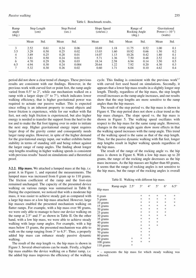
3.2.1. Benchmark results. We first present the results ofthe gait patterns of our passive walker with various rampangles as the benchmark results. The friction coefficientofthe ramp is 0.24 and the foot-size is 3.1 cm� 0.9 cm. Wemanaged to have our device walking steadily on the rampwith the ramp angle ranging from 3° to 7°. The measuredand calculated gait parameters are shown in Table I. Fromthis table, one can observe that, as the ramp angle increases,the step length increases steadily, while the range of theside-to-side rocking angle decreases. However, our meas-urements do not show a clear trend of changes in the stepperiod. Our calculation shows that the walking speedincreases with the ramp angle, the same trend as that of thestep length, which indicates that longer step lengths result inhigher walking speeds. Thus, our experimental results showthat the ramp angle dictates the step length, walking speedand gravitational power.
It is interesting to compare the gait pattern of our walkerwith flat feet to the previous work where round feet or pointfeet were used. For example, in McGeer’s experimentalwork2 as well as other simulation studies,4,6,7 the step lengthwas also found to increase with the ramp angle, but the step
Passive walking254
period did not show a clear trend of changes. These previousresults are consistent with our findings. However, in theprevious work with curved feet or point feet, the ramp anglevaried from 0.5° to 2°, while our mechanism walked on aramp with a larger slope (3° to 7°), which indicates lowerwalking efficiency, that is higher gravitational power wasrequired to actuate our passive walker. This is expectedsince rolling is an inherent property to round objects andlower friction is experience, while for our walker with flatfeet, not only high friction is experienced, but also higherenergy is needed to transfer the support from the heel to thetoe and to make the flat foot tipping over in order to initiatethe next step. Higher gravitational energy input requireslarger drop of the gravity center and consequently needslarger ramp angles. However, in spite of the higher demandfor the gravitational energy input, our walker exhibits betterstability in terms of standing still and being robust againstthe larger range of ramp angles. The finding about longerstep lengths resulting in higher walking speeds is consistentwith previous results7 based on simulations and a theoreticalproof.
3.2.2. Hip mass. We attached a lumped mass at the hip, i.e.point A in Figure 1, and repeated the measurements. Thelumped mass was increased from 0 gram up to 110 grams.The friction coefficient of the ramp and the foot-sizeremained unchanged. The capacity of the presented devicewalking on various ramps was summarised in Table II.During the experiment, we noticed that with a moderate hipmass, it was easier to achieve steady gait as compared witha large hip mass or a low hip mass attached. However, largehip masses enabled the presented mechanism walking onflatter ramps. For example, with a hip mass over 90 grams,we were only able to manage to have our device walking onthe ramp at 2.5° and 3° as shown in Table II. On the otherhand, with a low hip mass, we were able to achieve steadywalking with large ramp angles. For example, with a hipmass below 15 grams, the presented mechanism was able towalk on the ramp ranging from 3° to 6.5°. Thus, a properlyadded hip mass can enhance steady passive dynamicwalking.
The result of the step length vs. the hip mass is shown inFigure 3. Several observations can be made. Firstly, a higherhip mass enables the device walking on a flatter ramp, i.e.the added hip mass improves the efficiency of the walking
cycle. This finding is consistent with the previous work2,7
with curved feet used based on simulations. Secondly, itappears that a lower hip mass results in a slightly longer steplength. Thirdly, regardless of the hip mass, the step lengthoverall increases as the ramp angle increases, and our resultsshow that the step lengths are more sensitive to the rampangles than the hip masses.
The result of the step period vs. the hip mass is shown inFigure 4. The step period does not show a clear trend as thehip mass changes. The slope speed vs. the hip mass isshown in Figure 5. The walking speed oscillates withrespect to the hip mass for the same ramp angle. However,changes in the ramp angle again show more effects in thatthe walking speed increases with the ramp angle. This trendof the walking speed is the same as that of the step length.Thus, for the passive dynamic walking with flat feet, longerstep lengths result in higher walking speeds regardless ofthe hip mass.
The result of the range of the rocking angle vs. the hipmass is shown in Figure 6. With a low hip mass up to 20grams, the range of the rocking angle decreases as the hipmass increases. As the hip masses are higher than 60 grams,it seems that the range of rocking angles is not sensitive tothe hip mass, but the range of the rocking angles is overall
Table I. Benchmark results.
Ramp Step Length Step Period Slope Speed Range of Gravitationalangle (cm) (sec.) (cm/sec.) Rocking Angle Power (� 10–2)(deg.) (deg.) (watts)
Mean Std. Mean Std. Mean Std. Mean Std. Mean Std.
3 2.52 0.61 0.24 0.06 10.69 1.18 11.75 0.52 1.00 0.13.5 3.29 0.50 0.25 0.02 13.03 1.60 10.92 0.66 1.50 0.24 3.89 0.25 0.28 0.01 14.07 1.13 10.26 0.42 1.80 0.15 3.81 0.50 0.24 0.01 5.71 1.36 7.50 0.48 2.52 0.26 4.70 0.29 0.26 0.03 18.34 2.58 6.94 0.14 3.50 0.5
6.5 4.94 0.30 0.24 0.004 20.64 1.22 7.92 0.20 4.30 0.37 5.32 0.30 0.26 0.02 0.60 1.71 6.04 0.10 4.62 0.4
Table II. Walking with different hip mass.
Ramp angle 2.5° 3° 4° 5° 6° 6.5°Hip mass
0 gram * * * * *5 grams * * * * *10 grams * * * * *15 grams * * * * *20 grams * * * *25 grams * * * *30 grams * * * *35 grams * * *40 grams * * *50 grams * * *60 grams * *70 grams * *80 grams * *90 grams * * *100 grams * * *110 grams *
* – represents the hip mass for which steady walking wasachieved.
Passive walking 255

Fig. 3. Step length vs. hip mass for all tested angles.
Fig. 4. Step period vs. hip mass for all tested angles.
Fig. 5. Slope speed vs. hip mass for all tested angles.
Passive walking256

lower than those with a lower hip mass at the same rampangle.
The gravitational power (Figure 7) shows a similarpattern as the one of the walking speed in that it increaseswith the ramp angle. At the same ramp angle, thegravitational power oscillates within a narrow band.
In summary, the important findings of the effects of theadded hip mass on passive dynamic walking with flat feetare that the added hip mass improves the efficiency ofwalking by allowing the device walking on flatter slopes,the gait parameters are more sensitive to the changes inramp angles as compared to the changes in the added hipmass. Higher ramp angles render longer step lengths, whichdictate the walking speeds and the gravitational power.
3.2.3. Friction coefficients. We also studied the effects offriction on passive walking. We used three different surfacesfor the ramp with a low friction coefficient (0.24),intermediate friction coefficient (0.33) and high frictioncoefficient (0.42). The foot-size was 3.1 cm� 0.9 cm and nohip mass was attached. The walking device can walk with a
minimum ramp angle of 3° for the ramp with a low frictioncoefficient. For the intermediate and high friction coeffi-cients, the lowest ramp angle at which the walker is still ableto walk is 4°. It is expected that the larger friction coefficientcauses higher energy dissipation, thus the walker requiresmore energy input. Larger ramp angles allow moregravitational energy to be injected to the walker tocompensate the energy loss due to the friction.
Referring to Figure 8, the step lengths with various rampangles for the low friction coefficient ramp are alwayshigher than those with the intermediate and high frictioncoefficients. For the ramp with intermediate and highfriction coefficients, the step lengths increase with the rampangles, the same as those for the low friction coefficientexcept for the ramp angle of 4°. Figure 9 shows that the stepperiods for the ramp with low friction coefficient are thehighest as compared with those belonging to the inter-mediate and high friction coefficients. The step periods donot change significantly with respect to the ramp angles.Referring to Figure 10, the slope speeds for the surface witha low friction coefficient are higher than those with theintermediate and high friction coefficients. The slope speed
Fig. 6. Range of rocking angle vs. hip mass for all tested angles.
Fig. 7. Gravitational power vs. hip mass for all tested angles.
Passive walking 257

Fig. 8. Step length vs. ramp angle for various friction coefficients.
Fig. 9. Step period vs. ramp angle for various friction coefficients.
Fig. 10. Slope speed vs. ramp angle for various friction coefficients.
Passive walking258

increases with the increase in the ramp angles regardless ofthe surface friction coefficient.
The rocking angles for the low friction coefficient are thehighest, followed by those with the intermediate and highfriction coefficients as shown in Figure 11. The ranges ofthe rocking angles tend to decrease with the increase in theramp angles. From Figure 12, we found that although thegravitational power for the ramp with the lowest frictioncoefficient is slightly higher than those for the ramps withhigher coefficients, the gravitational power consistentlyincreases with the ramp angle. This is another evidence thatthe step lengths dictate walking speeds and the gravitationalpower.
3.2.4. Foot lengths. We also investigated the effects of thelengths of the flat feet on walking. The friction coefficient ofthe ramp was 0.24 and no hip mass was attached. The samewalking device with various lengths of feet were used(2.2 cm, 2.5 cm, 2.7 cm, 2.8 cm, 3.1 cm and 3.3 cm). Thewidth of the feet remained unchanged (0.9 cm). However,we were only able to make our walking mechanism with thefeet lengths of 2.8 cm and 3.1 cm walking steadily. Theresults of step lengths, step periods, slope speeds, ranges ofrocking angles and the gravitational power are shown inFigures 13 to 17. The first observation is that the ranges ofrocking angles with shorter feet are significantly higher than
those with longer feet. Another observation is that the steplength, step period, slope speed, rocking angle range andgravitational power increases with the ramp angle regardlessthe lengths of feet.
4. CONCLUDING REMARKSIn this work, we constructed a two-straight-legged passivedynamic walker with flat feet. We further studied the effectsof changes in the ramp angle, hip mass, friction of the rampand foot length on the walking patterns systematically. Thewalking patterns were characterised by the step length, stepperiod, walking speed, side-to-side rocking angle andgravitational power. The purpose was to gain physicalinsights into the mechanics of passive walking.
We first found that as compared with other passivewalking devices with curved feet or point feet, the presentedwalker with flat feet can not only stand still, but also walksteadily down a ramp with a larger range of ramp angles.However, the presented passive walking device requiressignificantly higher ramp angles than those with curved feetor point feet, which indicates that the walking efficiency issignificantly lower. This is expected because higher energyis needed to transfer the support from the heel to the toe andto make the flat foot tipping over to initiate the next step.Like the passive walkers with curved feet, walking with flat
Fig. 11. Range of rocking angle vs. ramp angle for various friction coefficients.
Fig. 12. Gravitational power vs. ramp angle for various friction coefficients.
Passive walking 259

Fig. 13. Step length vs. ramp angle with various foot sizes.
Fig. 14. Step period vs. ramp angle for various foot sizes.
Fig. 15. Slope speed vs. ramp angle for various foot sizes.
Passive walking260

feet is dictated by the combination of dynamic parameters.The fact that the walker can settle in steady walking in spiteof the variations in parameters shows the robustness of thepassive dynamic walking. We also found that the dynamiceffects of the swinging motion, side-to-side rocking andyaw are internally coupled, and yaw is highly undesirablefor stable walking. Side-to-side rocking is required forstraight-legged walking devices and it may enhance thestability of walking if properly controlled. One of theeffective passive tools for controlling side-to-side rockingand yaw is the proper combination of the balancing massand its orientation. Another passive tool is to use free swingarms. Regardless the techniques, proper control of side-to-side rocking and yaw is essential for steady walking, whichindicates the importance of the role of human swingingarms in stable and energy-efficient walking and such a rolemay be inherent to a machine rather than driven by thecentral nerve system.
Regarding the effects of parameters, such as the rampangle, hip mass, ramp friction and foot length on the gaitpatterns, we found that changes in the ramp angle have the
most dominant effects on the gait patterns. More specifi-cally, as the ramp angle increases, the step length increasesregardless of the hip mass, friction coefficient and foot size.The step period does not show any clear trends with theincrease in the ramp angle. The walking speed and thegravitational power are dictated by the step length, andconsequently by the ramp angle. As the ramp angleincreases, the range of the rocking angle decreases regard-less of the friction coefficient and foot size. Another findingis related to the hip mass. An increase in the hip massimproves the walking efficiency by allowing the mechanismto walk on a flatter ramp. Also, a higher hip mass reducesthe step length as well as the rocking angle. The thirdinteresting finding is that 4° is a magic ramp angle for ourwalking device. It was significantly easier to have ourmechanism walking on a ramp of 4° as compared with otherramp angles regardless of hip masses, foot lengths andfrictions. The gait parameters associated with 4° ramp, suchas the step length, step period and rocking angle, are alsodistinguished from those with other ramp angles. We alsonoticed that the successful rate with the ramp angle of 4° is
Fig. 16. Range of rocking angle vs. ramp angle with various foot sizes.
Fig. 17. Gravitation power vs. ramp angle with various foot sizes.
Passive walking 261

the highest (about 90%) as compared with other rampangles. It seems that 4° of the ramp angle is an ideal slopefor our walker.
Most previous experimental studies on passive dynamicwalking have been limited to demonstrating the existence ofpassive gait for various passive walking mechanisms wherecurved feet were used. Very few have focused on thedetailed walking patterns. Through our experimental study,we not only demonstrated the existence of passive gait forthe presented walking device with flat feet, but alsoinvestigated the effects of various parameters on the gaitpatterns. The study is systematic and the results agree withlimited available simulation results qualitatively whereeither semicircular feet or point feet were used. Theimportance of this research lies within its connection tohuman gait, as well as to the development of energy-eff cient bipedal robots. This work, along with otherresearch on passive dynamic walking, enables us to gain abetter understanding on the mechanics of walking. Such anunderstanding can have positive impact on design of betterprostheses and on the active control aspects of walking.
References1. A. H. Collins, M. Wisse and A. Ruina, “Three-dimensional
passive-dynamic walking robot with two legs and knees”, Int.J. Robotics Research 20, No. 7, 607–615 (2001).
2. T. McGeer, “Passive dynamic walking”, Int. J. RoboticsResearch 9, No. 2, 62–82 (1990).
3. M. J. Coleman and A.Ruina, “An uncontrolled toy that canwalk but cannot stand still”, Physical Review Letters 80, No.16, 3658–3661 (1998).
4. M. Garcia, A. Chatterjee, A. Ruina and M. Coleman, “Thesimplest walking model: stability, complexity, and scaling”,ASME Journal of Biomechanical Engineering 120, No. 2,281–288 (1998).
5. M. Garcia, A. Chatterjee and A. Ruina, “Efficiency, speed andscaling of two-dimensional passive-dynamic walking”,Dynamics and Stability of Sysfems 15, 2, 75–99 (2000).
6. A. D. Kuo, “Stabilization of lateral motion dynamic walking”,Int. J. Robotics Research 18, No. 9, 917–930 (1999).
7. A. Chatterjee and M. Garcia, “Small slope implies low speedfor McGeer’s passive walking machines”, Dynamics andStability of Systems 15, 139–157 (2000).
8. M. Wisse, A. L. Schwab and R. Q. van der Linde, “A 3Dpassive dynamic biped with yaw and roll compensation”,Robotica 19, Part 3, 275–284 (2001).
9. H. Elftman, “The Function of Arms in Walking”, HumanBiology 11, 529–535 (1939).
Passive walking262


![Powered Bipeds Based on Passive Dynamic Principlessoa/paperweb/pubs/Anderson... · Powered Bipeds Based on Passive Dynamic Principles ... pattern generator-based walking [5], ...](https://static.fdocuments.net/doc/165x107/5aebe5af7f8b9a585f8e335b/powered-bipeds-based-on-passive-dynamic-soapaperwebpubsandersonpowered-bipeds.jpg)