An Engine System Approach to Exhaust Waste … Non-Confidential An Engine System Approach to Exhaust...
23
Caterpillar Non-Confidential An Engine System Approach to Exhaust Waste Heat Recovery Principal Investigator: Richard W. Kruiswyk Caterpillar Inc. DOE Contract: DE-FC26-05NT42423 DOE Technology Manager: John Fairbanks NETL Project Manager: Carl Maronde DOE DEER Conference Dearborn, MI. September 29, 2010 Note: This presentation does not contain any proprietary, confidential, or otherwise restricted information.
Transcript of An Engine System Approach to Exhaust Waste … Non-Confidential An Engine System Approach to Exhaust...

Caterpillar Non-Confidential
An Engine System Approach to Exhaust Waste Heat Recovery
Principal Investigator: Richard W. KruiswykCaterpillar Inc.
DOE Contract: DE-FC26-05NT42423DOE Technology Manager: John FairbanksNETL Project Manager: Carl Maronde
DOE DEER ConferenceDearborn, MI.September 29, 2010
Note: This presentation does not contain any proprietary, confidential, or otherwise restricted information.

Caterpillar Non-Confidential
Disclaimer
The work described in this presentation, conducted under the Caterpillar / DOE cooperative research agreement, was conducted by the Technology and Solutions Division (T&SD) of Caterpillar Inc. The cooperative research described in the presentation was done to evaluate proof-of-concept for technologies that meet EPA 2010 on-highway emissions with the potential to improve peak brake thermal efficiency by 10%. Cursory consideration was given to which technologies may have some ability to be commercialized by the engine divisions of Caterpillar which have commercialization responsibility.
The process to validate technologies as commercially viable was not in the scope of the program, nor was it undertaken. Commercialization aspects such as cost/benefit analysis, reliability, durability, serviceability and packaging across multiple applications were only considered at a cursory level. Until such analysis is completed,any attempt to imply commercial viability as a result of the material in this presentation is not justified.
Copyright: ©2010 Caterpillar Inc. All Rights Reserved
Trademark: CAT, CATERPILLAR, their respective logos, “Caterpillar Yellow” and the “Power Edge” trade dress, as well as corporate and product identity used herein, are trademarks of Caterpillar and may not be used without permission.

Caterpillar Non-Confidential
AGENDA
• EWHR Program Objectives, Timeline, Scope
• Technical Developments
• Summary and Conclusions

Caterpillar Non-Confidential
AGENDA
• EWHR Program Objectives, Timeline, Scope
• Technical Developments
• Summary and Conclusions

Caterpillar Non-Confidential
Program Objective
Develop components, technologies, and methods torecover energy lost in the exhaust processes of aninternal combustion engine and utilize that energy toimprove engine thermal efficiency by 10% (i.e. from ~42% to ~46% thermal efficiency)
No increase in emissions rate
No reduction in power density
Compatible with anticipated aftertreatment

Caterpillar Non-Confidential
Phase 2
20062005
DefineRoadmap
2007
Phase 1
Validateroadmap
Phase 3
Mid-Program System Demo
Program Phases Per Contract
Program Timeline
Continue development of promising technologies2010
END OF PROGRAM
20092008
Originally planned as a 5 Phase Program
Truncated to 3 Phases – migration to Supertruck
Final program report Technologies developed
Key results & lessons learned

Caterpillar Non-Confidential
Ambient
Stack
Engine C15
A/C
LP Comp
HP Comp
LP Turb
HP Turb
DPF
CGICooler CGI
BrakePower
Ambient
Stack
Engine C15
A/C
LP Comp
HP Comp
LP Turb
HP TurbHP Turb
DPF
CGICooler CGI
BrakePower
HE
ApproachAn integrated system solution
to waste heat recovery
Numbers in ( ) indicate % increase in thermal efficiency from this component
Baseline C15 15.2L On-Highway Truck Engine
LPL (low pressure loop) configuration
Port Insul.(0.5%)
Piping(0.5%)
Intercooling(1.3%)
I/C
HP Turbine(2.0%)
LP Turbine(1.0%)Compressors
(0.7%)•Turbocompound or bottoming cycle: supplements engine power via electrical or mechanical connection to flywheel
Stack Recovery*(4.0%)
Strategy Optimization

Caterpillar Non-Confidential
Program Philosophy• “System” Solution
– Modular; “Best” elements can be carried to production
• Production-Viable Technologies
– Cost, Packaging, Manufacturing
• Broad Emissions Architecture Applicability
– Viable for HPL, LPL, or non-EGR solutions
– Compatible w/ Aftertreatment

Caterpillar Non-Confidential
AGENDA
• EWHR Program Objectives, Timeline, Scope
• Technical Developments
• Summary and Conclusions

Caterpillar Non-Confidential
RND Gen1 vs Baseline Radial HP
0.68
0.7
0.72
0.74
0.76
0.78
0.8
0.82
0.84
0.6 0.65 0.7 0.75 0.8
Velocity Ratio, U/C
Turb
ine-
Mec
h Ef
f, T-
S, (
%)
Bsln
target
2%
HP Turbine Efficiency Target RND Gen1 vs Baseline Radial HP
0.68
0.7
0.72
0.74
0.76
0.78
0.8
0.82
0.84
0.6 0.65 0.7 0.75 0.8
Velocity Ratio, U/C
Turb
ine-
Mec
h Ef
f, T-
S, (
%)
Bsln
target
2%
RND Gen1 vs Baseline Radial HP
0.68
0.7
0.72
0.74
0.76
0.78
0.8
0.82
0.84
0.6 0.65 0.7 0.75 0.8
Velocity Ratio, U/C
Turb
ine-
Mec
h Ef
f, T-
S, (
%)
Bsln
target
2%
HP Turbine Efficiency Target
Technical Progress – HP Turbine +2%
Peak efficiency shift required for +2% engine thermal efficiency
Target: + 2% Engine Thermal Efficiency: • + 8% Turbine Stage Efficiency• Improved Exhaust Pulse Utilization
Technologies• RND turbine• Mixed Flow turbine

Caterpillar Non-Confidential
0.4000
0.4500
0.5000
0.5500
0.6000
0.6500
0.7000
0.7500
0.8000
0.8500
0.4000 0.5000 0.6000 0.7000 0.8000 0.9000 1.0000 1.1000
5%
Imperial College Test Data
Gas Stand Test Results
Base TurbineRND Turbine
Velocity ratio, U/C
Tur
bine
Aer
o ef
ficie
ncy
(T-S
)
0.4000
0.4500
0.5000
0.5500
0.6000
0.6500
0.7000
0.7500
0.8000
0.8500
0.4000 0.5000 0.6000 0.7000 0.8000 0.9000 1.0000 1.1000
5%
Imperial College Test Data
Gas Stand Test Results
Base TurbineRND Turbine
0.4000
0.4500
0.5000
0.5500
0.6000
0.6500
0.7000
0.7500
0.8000
0.8500
0.4000 0.5000 0.6000 0.7000 0.8000 0.9000 1.0000 1.1000
5%
Imperial College Test Data
Gas Stand Test Results
Base TurbineRND Turbine
Velocity ratio, U/C
Tur
bine
Aer
o ef
ficie
ncy
(T-S
)
Technical Progress – HP Turbine +2%
+
Technology 1 – Radial, Nozzled, Divided (RND) Turbine• High efficiency turbine wheel • Nozzled and divided turbine housing
• + 5-6% turbine efficiency• Full map width benefits

Caterpillar Non-Confidential
BSFC ∆ - RND vs Base Radial Turbine
1.3
1.6
0.4
2.2
2.2
1.1
3.0
1.7
1.0
0.0
500.0
1000.0
1500.0
2000.0
2500.0
3000.0
900 1100 1300 1500 1700 1900 2100
SPEED
LOA
D
Engine Speed
Eng
ine
Loa
d
0
0.5
1
1.5
2
2.5
3
3.5
800 1000 1200 1400 1600 1800 2000
ENGINE SPEED (rpm)
TIM
E (s
ec)
0
5
10
15
20
25
30
35
40
Peak
Sm
oke
Opa
city
, %
Engine Speed
Res
pons
e T
ime
Smok
e
Response TestingBSFC - % Improvement with RND Turbine
30% improvement in response
BslnRND
Technical Progress – HP Turbine +2%
+
Technology 1 – Radial, Nozzled, Divided (RND) Turbine• High efficiency turbine wheel • Nozzled and divided turbine housing
Durability testing underway• Successful completion of nozzle ring thermal cycle test
On-Engine Test Results: Single-stage turbo HPL EGR engine
Caterpillar Non-Confidential
0.4000
0.4500
0.5000
0.5500
0.6000
0.6500
0.7000
0.7500
0.8000
0.8500
0.40000 0.50000 0.60000 0.70000 0.80000 0.90000 1.00000 1.10000
Velocity ratio, U/C
Tur
bine
Aer
o ef
ficie
ncy
(T-S
)
5%
Imperial College Test Data
Gas Stand Test Results
Base TurbineMixed Flow Turbine
0.4000
0.4500
0.5000
0.5500
0.6000
0.6500
0.7000
0.7500
0.8000
0.8500
0.40000 0.50000 0.60000 0.70000 0.80000 0.90000 1.00000 1.10000
Velocity ratio, U/C
Tur
bine
Aer
o ef
ficie
ncy
(T-S
)
5%
Imperial College Test Data
Gas Stand Test Results
Base TurbineMixed Flow Turbine
Technical Progress – HP Turbine +2%
Technology 2 – Mixed Flow Turbine• Nozzle-less, divided volute
• + 2-3% turbine efficiency• Efficiency peak at lower U/C a improved exhaust pulse utilization
• + 5-6% efficiency at lower U/C
radial mixed flowradial mixed flowfirst-pass

Caterpillar Non-Confidential
BSFC ∆ - Mixed Flow vs Radial HP Turbine
1.3
1.5
1.4
3.1
1.3
1.1
0.4
2.6
-0.2
-0.1
-0.6
0.0
200.0
400.0
600.0
800.0
1000.0
1200.0
1400.0
1600.0
1800.0
900 1100 1300 1500 1700 1900 2100
SPEED
LOA
D
Engine Speed
Eng
ine
Loa
d
BSFC - % Improvement with Mixed Flow TurbineBSFC ∆ - Mixed Flow vs Radial HP Turbine
1.3
1.5
1.4
3.1
1.3
1.1
0.4
2.6
-0.2
-0.1
-0.6
0.0
200.0
400.0
600.0
800.0
1000.0
1200.0
1400.0
1600.0
1800.0
900 1100 1300 1500 1700 1900 2100
SPEED
LOA
D
Engine Speed
Eng
ine
Loa
d
BSFC - % Improvement with Mixed Flow Turbine
Technical Progress – HP Turbine +2%
On-Engine Test Results: Series turbo LPL EGR engine
Engine Speed
Eng
ine
Loa
d
Technology 2 – Mixed Flow Turbine• Nozzle-less, divided volute
radial mixed flowradial mixed flowfirst-pass
• 1 to 1.5% fuel economy benefit at low and mid speed range where exhaust pulse energy is significant
Development of mixed-flow, nozzled, divided turbine is underway
BSFC - % Improvement with Mixed Flow Turbine

Caterpillar Non-Confidential
0.68
0.7
0.72
0.74
0.76
0.78
0.8
0.82
0.84
0.65 0.7 0.75 0.8 0.85 0.9
Velocity Ratio, U/C
Turb
-Mec
h E
ff, T
-S
2%
0.68
0.7
0.72
0.74
0.76
0.78
0.8
0.82
0.84
0.65 0.7 0.75 0.8 0.85 0.9
Velocity Ratio, U/C
Turb
-Mec
h E
ff, T
-S
2%
EWHR LP
BSLN LP
Gas Stand Turbine Efficiencies
0.68
0.7
0.72
0.74
0.76
0.78
0.8
0.82
0.84
0.65 0.7 0.75 0.8 0.85 0.9
Velocity Ratio, U/C
Turb
-Mec
h E
ff, T
-S
2%
0.68
0.7
0.72
0.74
0.76
0.78
0.8
0.82
0.84
0.65 0.7 0.75 0.8 0.85 0.9
Velocity Ratio, U/C
Turb
-Mec
h E
ff, T
-S
2%
EWHR LP
BSLN LP
Gas Stand Turbine Efficiencies
• + 4% peak turbine efficiency
Gas Stand Test Results
Velocity Ratio, U/C
Turb
ine-
Mec
hani
cal E
ff, T
-S
0.68
0.7
0.72
0.74
0.76
0.78
0.8
0.82
0.84
0.65 0.7 0.75 0.8 0.85 0.9
Velocity Ratio, U/C
Turb
-Mec
h E
ff, T
-S
2%
0.68
0.7
0.72
0.74
0.76
0.78
0.8
0.82
0.84
0.65 0.7 0.75 0.8 0.85 0.9
Velocity Ratio, U/C
Turb
-Mec
h E
ff, T
-S
2%
EWHR LP
BSLN LP
Gas Stand Turbine Efficiencies
0.68
0.7
0.72
0.74
0.76
0.78
0.8
0.82
0.84
0.65 0.7 0.75 0.8 0.85 0.9
Velocity Ratio, U/C
Turb
-Mec
h E
ff, T
-S
2%
0.68
0.7
0.72
0.74
0.76
0.78
0.8
0.82
0.84
0.65 0.7 0.75 0.8 0.85 0.9
Velocity Ratio, U/C
Turb
-Mec
h E
ff, T
-S
2%
EWHR LP
BSLN LP
Gas Stand Turbine Efficiencies
• + 4% peak turbine efficiency
Gas Stand Test Results
0.68
0.7
0.72
0.74
0.76
0.78
0.8
0.82
0.84
0.65 0.7 0.75 0.8 0.85 0.9
Velocity Ratio, U/C
Turb
-Mec
h E
ff, T
-S
2%
0.68
0.7
0.72
0.74
0.76
0.78
0.8
0.82
0.84
0.65 0.7 0.75 0.8 0.85 0.9
Velocity Ratio, U/C
Turb
-Mec
h E
ff, T
-S
2%
EWHR LP
BSLN LP
Gas Stand Turbine Efficiencies
0.68
0.7
0.72
0.74
0.76
0.78
0.8
0.82
0.84
0.65 0.7 0.75 0.8 0.85 0.9
Velocity Ratio, U/C
Turb
-Mec
h E
ff, T
-S
2%
0.68
0.7
0.72
0.74
0.76
0.78
0.8
0.82
0.84
0.65 0.7 0.75 0.8 0.85 0.9
Velocity Ratio, U/C
Turb
-Mec
h E
ff, T
-S
2%
EWHR LP
BSLN LP
Gas Stand Turbine Efficiencies
• + 4% peak turbine efficiency
0.68
0.7
0.72
0.74
0.76
0.78
0.8
0.82
0.84
0.65 0.7 0.75 0.8 0.85 0.9
Velocity Ratio, U/C
Turb
-Mec
h E
ff, T
-S
2%
0.68
0.7
0.72
0.74
0.76
0.78
0.8
0.82
0.84
0.65 0.7 0.75 0.8 0.85 0.9
Velocity Ratio, U/C
Turb
-Mec
h E
ff, T
-S
2%
EWHR LP
BSLN LP
Gas Stand Turbine Efficiencies
0.68
0.7
0.72
0.74
0.76
0.78
0.8
0.82
0.84
0.65 0.7 0.75 0.8 0.85 0.9
Velocity Ratio, U/C
Turb
-Mec
h E
ff, T
-S
2%
0.68
0.7
0.72
0.74
0.76
0.78
0.8
0.82
0.84
0.65 0.7 0.75 0.8 0.85 0.9
Velocity Ratio, U/C
Turb
-Mec
h E
ff, T
-S
2%
EWHR LP
BSLN LP
Gas Stand Turbine Efficiencies
• + 4% peak turbine efficiency
Gas Stand Test Results
Velocity Ratio, U/C
Turb
ine-
Mec
hani
cal E
ff, T
-S
Technical Progress – LP Turbine+1%Target: + 1% Engine Thermal Efficiency:
• + 6% Turbine Stage EfficiencyTechnology 1 – High Efficiency Axial Turbine
• +6% turbine efficiency verified – analysis, test• Packaging concerns w/ series turbos
Technology 2 – High Efficiency, Nozzled, Radial Turbine• Minimal impact on response – design freedom

Caterpillar Non-Confidential
1
1.2
1.4
1.6
1.8
2
2.2
2.4
2.6
2.8
0.1 0.15 0.2 0.25 0.3 0.35 0.4Flow
Pres
sure
Rat
io
0.620.66
0.70.720.740.76
0.70.80.81
0.82
• efficiency 1-1.5% > production• ½ of target achieved
Gas Stand Test Results
0.78
1
1.2
1.4
1.6
1.8
2
2.2
2.4
2.6
2.8
0.1 0.15 0.2 0.25 0.3 0.35 0.4Flow
Pres
sure
Rat
io
0.620.66
0.70.720.740.76
0.70.80.81
0.82
• efficiency 1-1.5% > production• ½ of target achieved
Gas Stand Test Results
1
1.2
1.4
1.6
1.8
2
2.2
2.4
2.6
2.8
0.1 0.15 0.2 0.25 0.3 0.35 0.4Flow
Pres
sure
Rat
io
0.620.66
0.70.720.740.76
0.70.80.81
0.82
• efficiency 1-1.5% > production• ½ of target achieved
Gas Stand Test Results
0.78
Technical Progress – Compressors
+0.7%Target: + 0.7% Engine Thermal Efficiency:
• + 2.5% Compressor Stage Efficiencies
HP Technology – Highly backswept wheel w/ vaned diffuser

Caterpillar Non-Confidential
Target: + 4% Engine Thermal Efficiency• Stack recovery on baseline LPL engine• Turbocompound downselected
• Brayton Cycle investigated – packaging challenges
+4%Technical Progress – Stack Recovery
0.0%
1.0%
2.0%
3.0%
4.0%
5.0%
6.0%
7.0%
0 5 10 15 20 25 30
Backpressure (kPa)
BSF
C B
enef
it
85% Transmission Efficiency90% Transmission Efficiency95% Transmission Efficiency
Peak Torque Conditions
0.0%
1.0%
2.0%
3.0%
4.0%
5.0%
6.0%
7.0%
0 5 10 15 20 25 30
Backpressure (kPa)
BSF
C B
enef
it
85% Transmission Efficiency90% Transmission Efficiency95% Transmission Efficiency
Peak Torque ConditionsEngine Simulation Results Technologies
• Mechanical Turbocompound
• Electrical Turbocompound

Caterpillar Non-Confidential
• Robust, high-efficiency bearing is challenge
Target: + 4% Engine Thermal Efficiency• Stack recovery on baseline LPL engine
+4%Technical Progress – Stack Recovery
Technology 1 – Mechanical Turbocompound
50krpm
0.0
0.001
0.002
-0.001
-0.002
Instrumentation
Gas Stand
• Developed power turbine gas stand test method• Detailed shaft motion measurements
• Test Conditions• 5 bearing systems• Speeds from 25-60krpm
• Gas Stand Test Results• < 0.002” shaft motion• 80-84% aero efficiency
Shaft Motion Results

Caterpillar Non-Confidential
Target: + 4% Engine Thermal Efficiency• Stack recovery on baseline LPL engine
+4%Technical Progress – Stack Recovery
Technology 2 – Electrical Turbocompound
50krpm
0.0
0.001
0.002
-0.001
-0.002
Gas Stand
Instrumentation
• Concept 2 analysis results• Generator efficiencies > 96% • Peak rotor stress acceptable• Peak stator temperature acceptable• Peak magnet temperature acceptable• Bending critical speed acceptable
3rd Critical Speed (87 krpm)
Shaft11
5 10 1520 25 30
35 40 45Shaft1
47
-4
-3
-2
-1
0
1
2
3
4
0 2 4 6 8 10 12
Axial Location, inches
Shaf
t Rad
ius,
inc
hes
< >
Re(x)
Turbine
Motor / Generator
Compressor Turbine
Motor / Generator
Compressor
• Two concept designs developed / analyzed• Concept 1: Generator in front of compressor
• Rotordynamic / packaging challenges• Concept 2: Generator between wheels
• Thermal management challenges
Development Ongoing: TSB-Funded Program

Caterpillar Non-Confidential
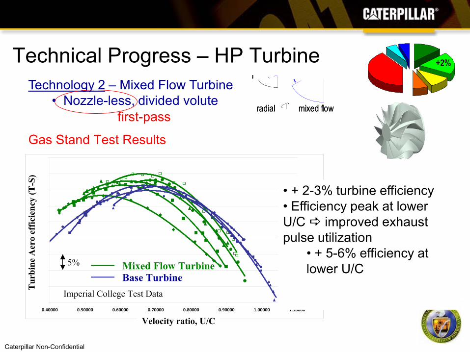
Port Insul.(0.5%)
Piping(0.5%) Intercooling
(1.3%)
High Eff.HP Turbine(2.0%)
High Eff.LP Turbine(1.0%)Compressors
(0.7%)
Stack Recovery(4.0%)
* Turbocompound or Bottoming Cycle
Port Insul.(0.5%)
Port Insul.(0.5%)
Piping(0.5%)Piping(0.5%) Intercooling
(1.3%)Intercooling
(1.3%)
High Eff.HP Turbine(2.0%)
High Eff.HP Turbine(2.0%)
High Eff.LP Turbine(1.0%)
High Eff.LP Turbine(1.0%)Compressors
(0.7%)Compressors
(0.7%)
Stack Recovery(4.0%)
* Turbocompound or Bottoming Cycle
Stack Recovery(4.0%)
Stack Recovery(4.0%)
* Turbocompound or Bottoming Cycle
Summary
Strategy Optimization
Thermal Eff. Improvement
Design point demo - target: +9.0%
“Mid-Program” Proof-of-Concept Demo*
*Not commercially validated
Design point demo - achieved: +7.0%
“Virtual” Demo:Engine Simulation using measured component performance maps
-0.7% • Used RND turbine• Mixed Flow ND will improve
-0.4% • Used radial turbine map (better packaging vs axial)-0.5%
• HP compressor ~ ½ of goal achieved• No change yet to LP compressor
-0.4% • Effect of lowercomponentefficiencies
Caterpillar Non-Confidential
Port Insul.(0.5%)
Piping(0.5%) Intercooling
(1.3%)
High Eff.HP Turbine(2.0%)
High Eff.LP Turbine(1.0%)Compressors
(0.7%)
Stack Recovery(4.0%)
* Turbocompound or Bottoming Cycle
Port Insul.(0.5%)
Port Insul.(0.5%)
Piping(0.5%)Piping(0.5%) Intercooling
(1.3%)Intercooling
(1.3%)
High Eff.HP Turbine(2.0%)
High Eff.HP Turbine(2.0%)
High Eff.LP Turbine(1.0%)
High Eff.LP Turbine(1.0%)Compressors
(0.7%)Compressors
(0.7%)
Stack Recovery(4.0%)
* Turbocompound or Bottoming Cycle
Stack Recovery(4.0%)
Stack Recovery(4.0%)
* Turbocompound or Bottoming Cycle
Summary
Strategy Optimization
Thermal Eff. Improvement
Design point demo - target: +9.0%
“Mid-Program” Proof-of-Concept Demo*
*Not commercially validated
Design point demo - achieved: +7.0%
“Virtual” Demo:Engine Simulation using measured component performance maps
Without these elements, value of turbocompound is just 2%
Caterpillar Non-Confidential
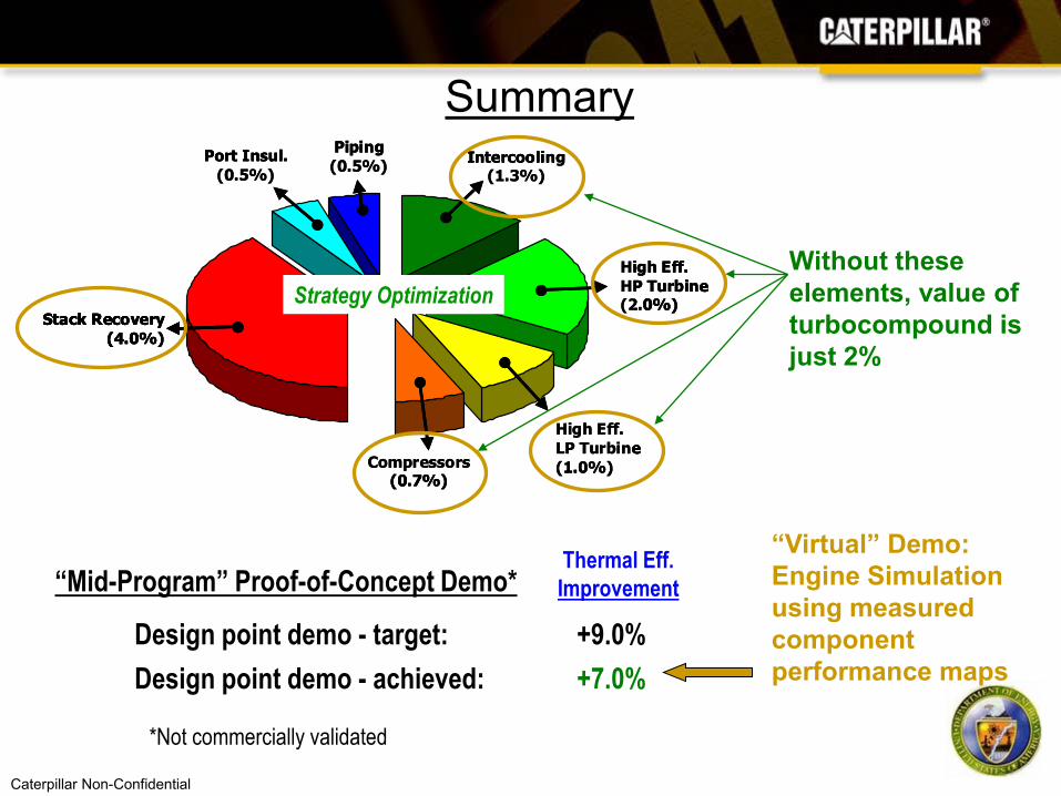
Acknowledgements
Turbomachinery design consulting, component procurement and integration.
Turbomachinery design consulting & optimization.
Turbomachinery design consulting & optimization.
Caterpillar Thanks:
Electric turbocompound design consulting
Honeywell
ConceptsNREC
Turbo Solutions
Barber-Nichols Inc.
Gas stand testing of advanced turbomachinery components
Imperial College
On-engine testing of advanced turbomachinery components
Oak Ridge National Lab

Caterpillar Non-Confidential
Acknowledgements
• Department of Energy• Gurpreet Singh• John Fairbanks
• DOE National Energy Technology Laboratory• Carl Maronde
Caterpillar Thanks: