Ambient Light Guiding System for the Mobility Support of Elderly...
56
Ambient Light Guidin for the Mobility Supp Solution package descri Deliverable Name: D3.1 - Deliverable Date: 14.11. Classification: Repor Authors: Marku Christi Document Version: 5.0 Project Coordinator: Fachh Project Partners: Tridon Barten myVita apollis YOUS AAL 201 ng System port of Elderly People iption - Solution package description .2013 rt & Prototype us Laner, Markus Canazei, Guido Kempte ian Bolkert hochschule Vorarlberg, Austria nic GmbH & Co KG, Austria nbach Lichtlabor GmbH, Austria ali AG, Switzerland s - Institut für Sozialforschung und Demos SE GmbH, Germany The project (Guiding Light) no AAL-201 funded under AAL JP 11-4-033 Guiding Light 1 er, Tom Ulmer, skopie OHG, Italy 11-4-033 is
Transcript of Ambient Light Guiding System for the Mobility Support of Elderly...
Ambient Light Guiding System for the Mobility Support of Elderly People
Solution package description
Deliverable Name: D3.1 -
Deliverable Date: 14.11.2013
Classification: Report & Prototype
Authors: Markus LanerChristian Bolkert
Document Version: 5.0
Project Coordinator: Fachhochschule Vorarlberg, Austria
Project Partners: Tridonic GmbH &Bartenbach Lichtlabor GmbH, AustriamyVitali AG, Switzerlandapollis YOUSE GmbH, Germany
AAL 2011
Ambient Light Guiding System for the Mobility Support of Elderly People
Solution package description
- Solution package description
.2013
Report & Prototype
Markus Laner, Markus Canazei, Guido KempterChristian Bolkert
Fachhochschule Vorarlberg, Austria
Tridonic GmbH & Co KG, Austria Bartenbach Lichtlabor GmbH, Austria myVitali AG, Switzerland apollis - Institut für Sozialforschung und Demoskopie OHG, ItalyYOUSE GmbH, Germany
The project (Guiding Light) no AAL-2011funded under AAL JP
AAL 2011-4-033 Guiding Light
1
Guido Kempter, Tom Ulmer,
Institut für Sozialforschung und Demoskopie OHG, Italy
2011-4-033 is

AAL 2011-4-033 Guiding Light
2
Preface This document forms part of the Research Project “Ambient Light Guiding System for the Mobility Support of Elderly People (Guiding Light)” funded by the Ambient Assisted Living Joint Programme (AAL-JP) as project number AAL 2011-4-033. The Guiding Light project will produce the following Deliverables:
D1.1 Medical, psychological, and technological framework
D2.1 Applicable hardware components
D2.2 Applicable software components
D3.1 Solution package description
D3.2 Implementation report
D4.1 Communication strategy
D4.2 Stakeholder management report
D5.1 Field test report
D6.1 Report on market analysis
D6.2 Dissemination plan
D6.3 Final business plan
D7.1 Consortium Agreement
D7.2 Periodic activity and project management report
D7.3 Final report
The Guiding Light project and its objectives are documented at the project website www.guiding-light.labs.fhv.at. More information on Guiding Light and its results can also be obtained from the project consortium:
Prof. Dr. Guido Kempter (project manager), University of Applied Sciences Vorarlberg (FHV), Phone: + 43 5572 792 7300, Email: [email protected]
Hermann Atz, Institute for Social Research and Opinion Polling OHG (APOLLIS), Phone: +39 0471 970115, Email: [email protected]
Dr. Christoph Nedopil, YOUSE GmbH (YOUSE), Phone: +49-89-21556347, Email: [email protected]
Mag. Wilfried Pohl, Bartenbach GmbH (BLL), Phone: +43-512-3338-66, Email: [email protected]
Dr. Heinz Seyringer, Tridonic GmbH & Co GK (TKG), Phone: +43-5572-390-26508, Email: [email protected]
Mag. Tom Ulmer, myVitali AG (MVA), Phone: +43-5574-90609-0, Email: [email protected]
AAL 2011-4-033 Guiding Light
3
Content
1. Overview .......................................................................................................................... 6
1.1. Introduction ...................................................................................................................... 6
1.2. Integrated overview of the GL-system ......................................................................... 7
2. Wired hardware solution ............................................................................................. 8
2.1. DALI©-based lighting control solution .......................................................................... 8
2.2. Actors ................................................................................................................................ 9
2.2.1. Electronic ballasts ........................................................................................................... 9
2.2.2. Light switch ...................................................................................................................... 9
2.3. Sensors ........................................................................................................................... 10
2.3.1. People counting sensor................................................................................................ 10
2.3.2. Passive infrared (PIR) sensor with Luxmeter ........................................................... 11
3. Wireless hardware solution ..................................................................................... 13
3.1. EnOcean© -based lighting control solution................................................................ 13
3.2. Gateway.......................................................................................................................... 14
3.3. Actors .............................................................................................................................. 16 3.3.1. Lighting control (electronic ballast) ............................................................................. 16
3.3.2. Light switch .................................................................................................................... 16
3.4. Sensors ........................................................................................................................... 17
3.4.1. Door contact sensor...................................................................................................... 17
3.4.2. Passive infrared (PIR) sensor with integrated brightness sensor ......................... 18
4. Lighting Solution ........................................................................................................ 20
4.1. Lighting Concept ........................................................................................................... 20
4.2. Luminaires ...................................................................................................................... 20
Ambient light 1 .......................................................................................................... 21
Ambient light 2 .......................................................................................................... 22
Task light 1 ................................................................................................................ 23
Task light 2 ................................................................................................................ 24
Task light 3 ................................................................................................................ 25
AAL 2011-4-033 Guiding Light
4
5. Design Process ........................................................................................................... 27
5.1. Lighting Design .............................................................................................................. 27
5.2. Sensor Design ............................................................................................................... 28
5.2.1. Installation of PIR sensors ........................................................................................... 28
5.2.2. Installation place of door contact sensor ................................................................... 29
5.3. Actor installation procedure ......................................................................................... 29
5.3.1. Installation of the light switches .................................................................................. 29
6. Lighting control ........................................................................................................... 29
6.1. Lighting control scheme ............................................................................................... 29
6.2. Presence-oriented control of ambient lighting components ................................... 30
6.3. Control of task lighting components ........................................................................... 31
6.3.1. Lighting control scheme to fulfil visual needs (Strategy 1) ..................................... 31
6.3.2. Lighting control scheme to support temporal orientation (Strategy 2) .................. 31
7. Software technology .................................................................................................. 35
7.1. Overview ......................................................................................................................... 35
7.2. System configuration .................................................................................................... 36
7.3. Lighting control .............................................................................................................. 38
7.4. User monitoring ............................................................................................................. 43
7.5. Bus system ..................................................................................................................... 47
7.6. Bus system plug-ins...................................................................................................... 48
8. Annex ............................................................................................................................. 56
8.1 References ...................................................................................................................... 56
AAL 2011-4-033 Guiding Light
5
List of Figures Fig. 1 Integrated overview of the GL-system ................................................................................ 7
Fig. 2 System architecture for a wired lighting control solution .................................................. 8
Fig. 3 Installation and setup of light barrier switch into doorframe .......................................... 10
Fig. 4 Amplifier and beam sensor of light barrier ....................................................................... 11
Fig. 5 Merten ARGUS Präsenz ..................................................................................................... 12
Fig. 6 System architecture for a wireless lighting control solution ........................................... 13
Fig. 7 Thermokon STC-Ethernet gateway ................................................................................... 15
Fig. 8 next.controller from AutomationNext ................................................................................. 15
Fig. 9 EnOcean door contact sensor ............................................................................................ 18
Fig. 10 EnOcean-based PIR-Sensor ............................................................................................ 19
Fig. 11 Main principle of zonally lighting within lighting control strategy 2 ............................. 32
Fig. 12 Exemplification of ambient lighting control curve .......................................................... 33
Fig. 13 Exemplification of all added task lighting control curves ............................................. 33
Fig. 14 Exemplification of task lighting control curve ................................................................. 34
Fig. 15 Overview of system architecture ..................................................................................... 35
Fig. 16 Assignment of sectors of motion sensors to room zones ............................................ 37
Fig. 17 Screenshot of next.manager from AutomationNext ..................................................... 38
Fig. 18 Example for dynamic lighting situation . ......................................................................... 39
Fig. 19 Overview about data flow in daily curve editor .............................................................. 40
Fig. 20 Screenshot of the daily curve editor user interface ...................................................... 41
Fig. 22 Process flow diagram of automatic lighting control by means of genetic algorithm 42
Fig. 21 Application for manually dimming lighting groups ........................................................ 42
Fig. 23 User monitoring data flow and storing ............................................................................ 43
Fig. 24 Expert GUI showing daily structure a motion profile of a test person ........................ 45
Fig. 25 Data flow diagram of the Web Application (Expert GUI) ............................................. 46
Fig. 26 Screenshot of user interface of Senior GUI ................................................................... 46
Fig. 27 Guiding Light system overall architecture ...................................................................... 48
Fig. 28 Daily curve node ................................................................................................................ 49
Fig. 29 Presence detection node .................................................................................................. 52
Fig. 30 State-diagram for presence/absence detection ............................................................ 52
Fig. 31 Multi-presence node .......................................................................................................... 53
Fig. 32 Light control converter node ............................................................................................. 54
AAL 2011-4-033 Guiding Light
6
1. Overview 1.1. Introduction Within the framework of Guiding Light (GL) an age-specific room lighting technology for private homes was developed. This new lighting system aims at improving indoor and outdoor mobility of healthy and progressively impaired elderly people living alone in their apartments. In newly built assisted living homes, the lighting system may be integrated to the home automation system (i.e. indoor illumination is one module besides the module heating, ventilation and air conditioning or the safety module). For this scenario a cable-based GL-solution was elaborated. On the other hand a vast amount of apartments of elderly people are in need of age-specific adaptation and renovation. Commonly these buildings are not equipped with a home automation system and thus the installation of a cable-based solution would cause high constructional efforts and is not feasible in many cases. Consequently a wireless GL-solution was developed to cover this scenario and take feasibility, cost and environmental installation impact aspects seriously. Due to its low installation efforts and its high adaptability (to changing needs of elderly people according to their actual physical and mental health and social status), the wireless GL-solution will mainly be promoted in the framework of the GL business development strategy. The first two chapters of D3.1 are dedicated to the description of the hardware components (control transmission technology, actors and sensors) of the GL-solution. While chapter 2 focuses on the hardware solution for the wired solution, chapter 3 describes the wireless hardware solution in detail. Subsequently the lighting design philosophy , based on the age-specific lighting requirements elaborated within deliverable D1.1, is described thoroughly. Additionally this chapter comprises a comprehensive overview of the newly developed lighting technology (new developed luminaire portfolio). It is a matter of fact that room infrastructure (e.g. room size, size and orientation of windows, furniture and its arrangement) strongly influences lighting design in case of a renewal of residential lighting systems. Due to its high variability an individual design process and adaption of the GL-system is needed. Chapter 5 gives an overview of the elementary design rules for the arrangement of luminaries, sensors and actors within the apartment. Thereby high attention is paid to the fact that these design guidelines enables qualified staff to plan and accomplish installations of the GL-system in the future. Within this AAL-project the GL-system will be installed in several private homes according to these design guidelines. All details of this planning and installation process will be described in deliverable D3.2 "Implementation report". This description will complement the specified design guidelines of D 3.1 and guide further GL-implementations in the future. Lighting needs of elderly people are changing over time. Some elderly people are requiring lighting primarily for strainless visual information processing (e.g. filing of drugs, reading, cleaning) and spatial orientation purposes. For this subset of elderly people the stabilisation of the circadian rhythm and gaining strong non-visual lighting effects is not high priority. On the other hand many elderly people progressively suffer from age-specific constraints and are consuming social services in order to stay at home for a longer period of time. These elderly people are in high demand of lighting interventions which support their non-visual lighting needs (e.g. improve sleep quality, mood or daytime vigilance by means of light). In order to comprise these complementary heterogenic lighting requirements two different lighting control schemes were developed and are presented in chapter 6. Additionally the software technology will be described in this chapter, too.
AAL 2011-4-033 Guiding Light
7
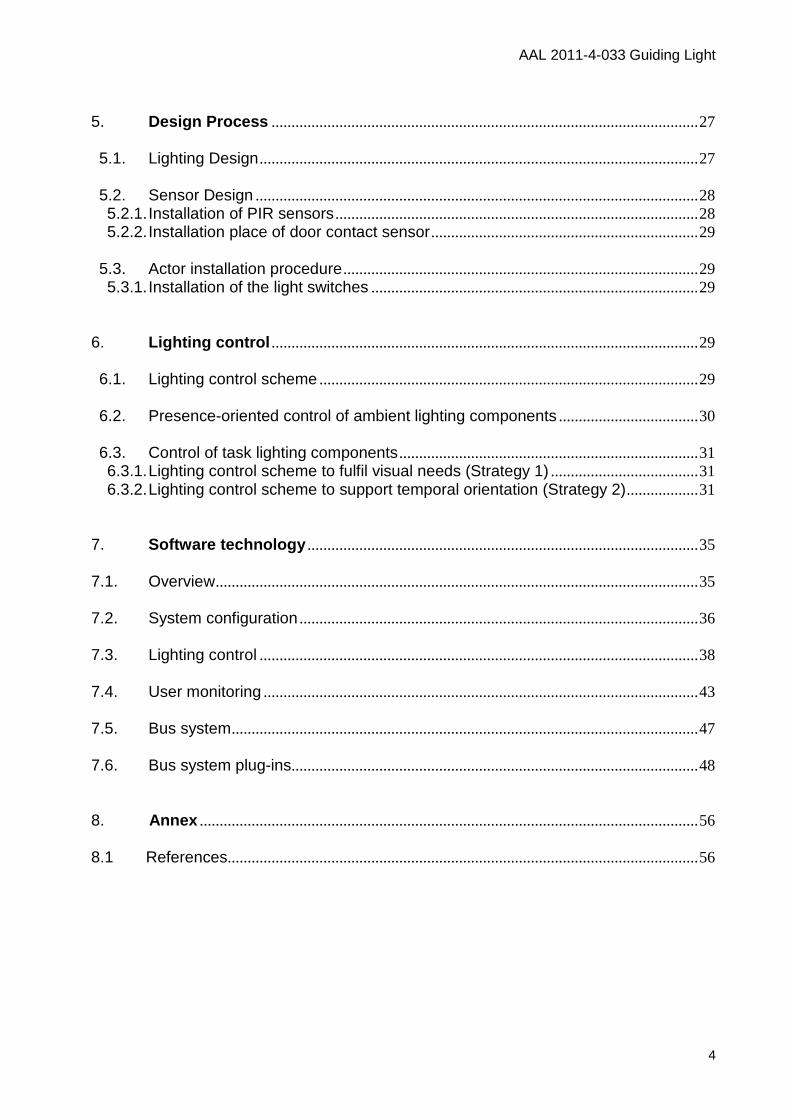
To sum up, deliverable D 3.1 documents the final technical solution. The decision-making process, preliminary concepts, interim solutions, technical surveys, etc. are well documented within the deliverables of work-package 2 "WP2 Intelligent room technologies". 1.2. Integrated overview of the GL-system
Fig. 1 Integrated overview of the GL-system
Fig. 1 is an integrated overview of the total "GL-system". It summarizes the different levels, components and procedures comprising a GL-system The most basic level is the system components level : It consists of the hardware components (sensors, luminaries, switches, gateways, etc.) and software components (i.e. bidirectional intelligent lighting control algorithm). Presence detection and activity monitoring algorithms are part of the software and located onto a server. The GL-system is connected and controlled via internet. Before a GL-system is installed in private households a preliminary design phase has to be accomplished. The design guidelines guaranty a correct positioning of sensors, luminaries and actors. The outcome of the design phase is summarized in an implementation handbook . The electrician installs and maintains the GL-system in private homes according to this handbook.
AAL 2011-4-033 Guiding Light
8
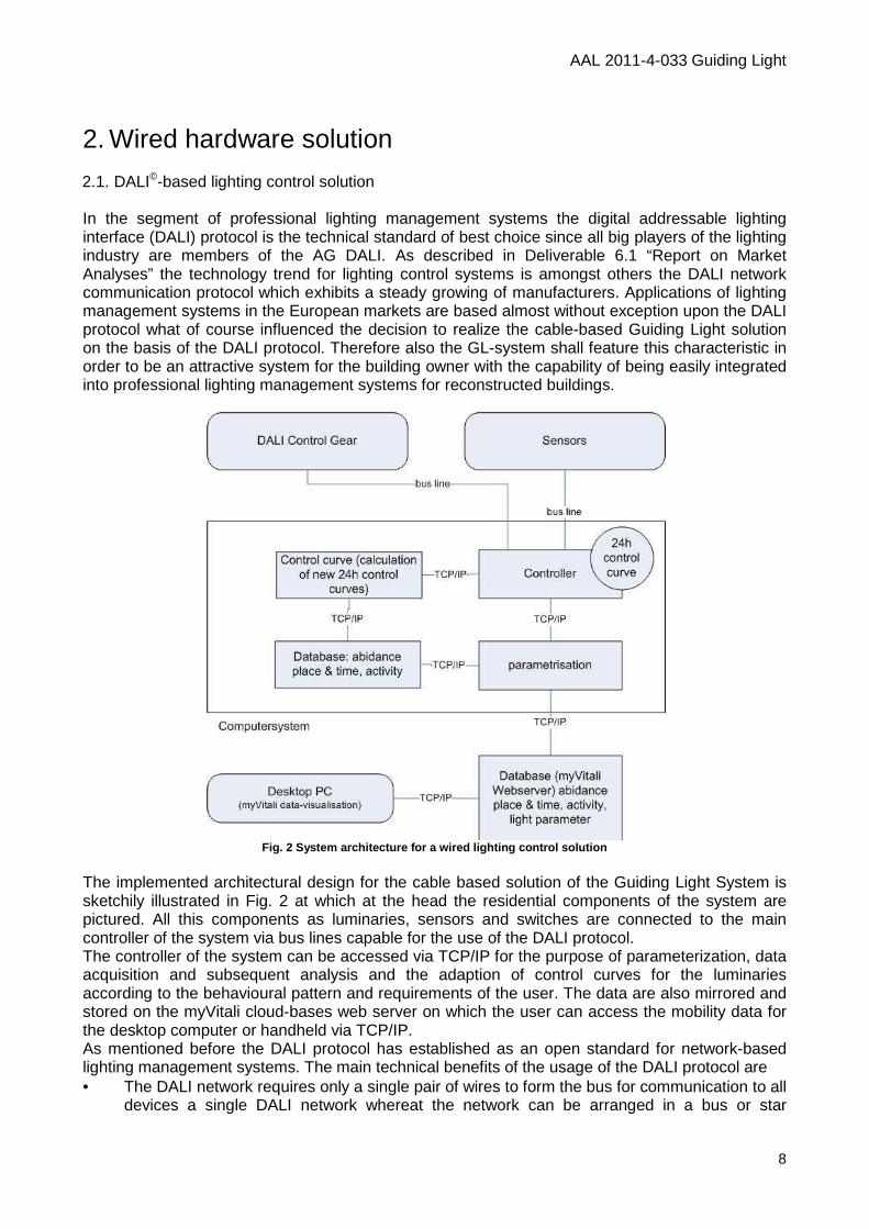
2. Wired hardware solution 2.1. DALI©-based lighting control solution In the segment of professional lighting management systems the digital addressable lighting interface (DALI) protocol is the technical standard of best choice since all big players of the lighting industry are members of the AG DALI. As described in Deliverable 6.1 “Report on Market Analyses” the technology trend for lighting control systems is amongst others the DALI network communication protocol which exhibits a steady growing of manufacturers. Applications of lighting management systems in the European markets are based almost without exception upon the DALI protocol what of course influenced the decision to realize the cable-based Guiding Light solution on the basis of the DALI protocol. Therefore also the GL-system shall feature this characteristic in order to be an attractive system for the building owner with the capability of being easily integrated into professional lighting management systems for reconstructed buildings.
Fig. 2 System architecture for a wired lighting con trol solution
The implemented architectural design for the cable based solution of the Guiding Light System is sketchily illustrated in Fig. 2 at which at the head the residential components of the system are pictured. All this components as luminaries, sensors and switches are connected to the main controller of the system via bus lines capable for the use of the DALI protocol. The controller of the system can be accessed via TCP/IP for the purpose of parameterization, data acquisition and subsequent analysis and the adaption of control curves for the luminaries according to the behavioural pattern and requirements of the user. The data are also mirrored and stored on the myVitali cloud-bases web server on which the user can access the mobility data for the desktop computer or handheld via TCP/IP. As mentioned before the DALI protocol has established as an open standard for network-based lighting management systems. The main technical benefits of the usage of the DALI protocol are • The DALI network requires only a single pair of wires to form the bus for communication to all
devices a single DALI network whereat the network can be arranged in a bus or star
AAL 2011-4-033 Guiding Light
9
topology. I.e. simple wiring of control lines by means of no group formation of devices and no featured polarity of the wiring.
• Each lighting device is assigned a unique static DALI short address in the numeric range 0 to 63, making it possible to include up to 64 devices on a single bus line. In addition to that each device can be assigned up to 16 groups and can feature up to 16 individually adjusted scenes. DALI can also be operated as a sub-system via DALI gateways in order to address more than 64 devices.
• The DALI protocol permits devices to be individually addressed and it also incorporates group and scene broadcast messages to simultaneously address multiple devices. I.e. a simultaneous control of individual units, or groups of units or of all units is possible at any time through individual addressing, group addressing or broadcast addressing (e.g. “address 1” go to 75% or scene 1, “group 1” go to 20% or scene 14, “all” go to scene 3). In addition various parameters, e.g. dimming speed, min-/max-values, re-grouping and scene values of the control devices can be set easily at any time and without re-wiring.
• The controller can monitor and control each lighting device by means of a bi-directional data exchange, i.e. e.g. device status messaging (lamp fault, power level, etc.) is possible.
No additional gateways are needed and no interference of data communication is expected in comparison with wireless solutions. 2.2. Actors 2.2.1. Electronic ballasts For the control of the GL luminaires DALI-compatible ballasts of the partner Tridonic is used. These devices can be connected directly to the DALI wiring and have the following technical specification:
Vendor Tridonic Series Constant Current Type LCAI 020/0500 A120 one4all (20W)
LCAI 2x050/0500 K013 one 4 all (2x50W) Retail price 107,90 EURO (20W)
170,00 EURO (2 x 50W) Technical design Power supply 230V, 50Hz, Functions DALI, DSI, Switch-Dim Dimension 207x42x31mmm
2.2.2. Light switch For manual switching existing switches can be used. The positioning of these switches is tied to electrical cabling and thus cannot be chosen freely without increased installation costs.
AAL 2011-4-033 Guiding Light
10
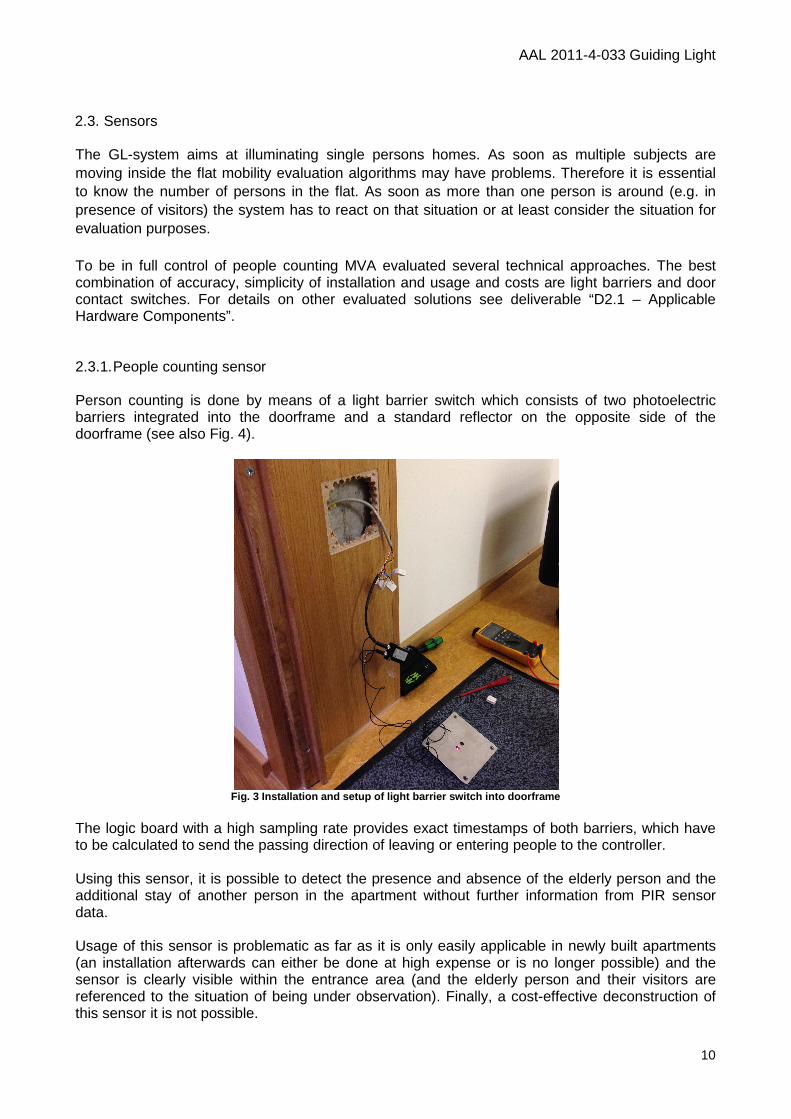
2.3. Sensors The GL-system aims at illuminating single persons homes. As soon as multiple subjects are moving inside the flat mobility evaluation algorithms may have problems. Therefore it is essential to know the number of persons in the flat. As soon as more than one person is around (e.g. in presence of visitors) the system has to react on that situation or at least consider the situation for evaluation purposes. To be in full control of people counting MVA evaluated several technical approaches. The best combination of accuracy, simplicity of installation and usage and costs are light barriers and door contact switches. For details on other evaluated solutions see deliverable “D2.1 – Applicable Hardware Components”. 2.3.1. People counting sensor Person counting is done by means of a light barrier switch which consists of two photoelectric barriers integrated into the doorframe and a standard reflector on the opposite side of the doorframe (see also Fig. 4).
Fig. 3 Installation and setup of light barrier swit ch into doorframe
The logic board with a high sampling rate provides exact timestamps of both barriers, which have to be calculated to send the passing direction of leaving or entering people to the controller. Using this sensor, it is possible to detect the presence and absence of the elderly person and the additional stay of another person in the apartment without further information from PIR sensor data. Usage of this sensor is problematic as far as it is only easily applicable in newly built apartments (an installation afterwards can either be done at high expense or is no longer possible) and the sensor is clearly visible within the entrance area (and the elderly person and their visitors are referenced to the situation of being under observation). Finally, a cost-effective deconstruction of this sensor it is not possible.
AAL 2011-4-033 Guiding Light
11
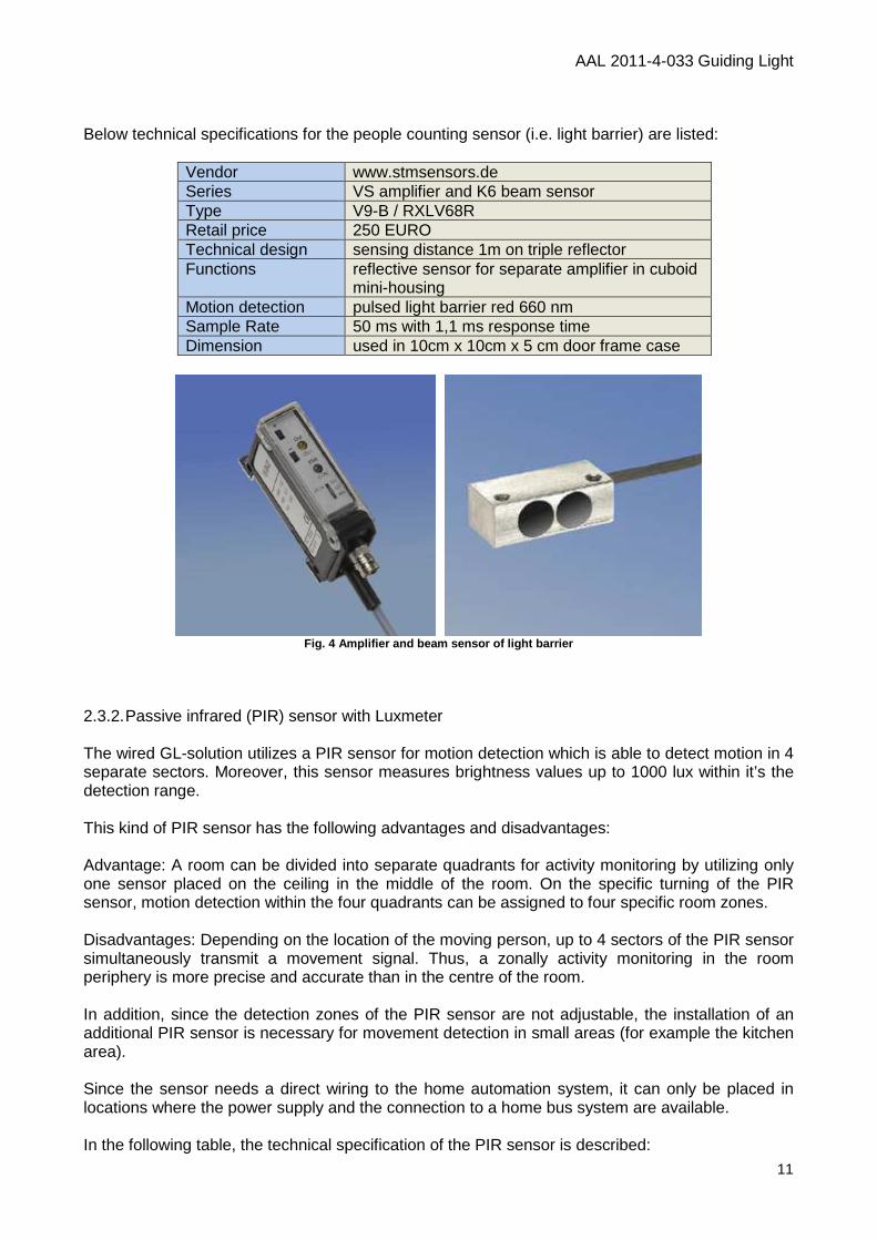
Below technical specifications for the people counting sensor (i.e. light barrier) are listed:
Vendor www.stmsensors.de Series VS amplifier and K6 beam sensor Type V9-B / RXLV68R Retail price 250 EURO Technical design sensing distance 1m on triple reflector Functions reflective sensor for separate amplifier in cuboid
mini-housing Motion detection pulsed light barrier red 660 nm Sample Rate 50 ms with 1,1 ms response time Dimension used in 10cm x 10cm x 5 cm door frame case
Fig. 4 Amplifier and beam sensor of light barrier
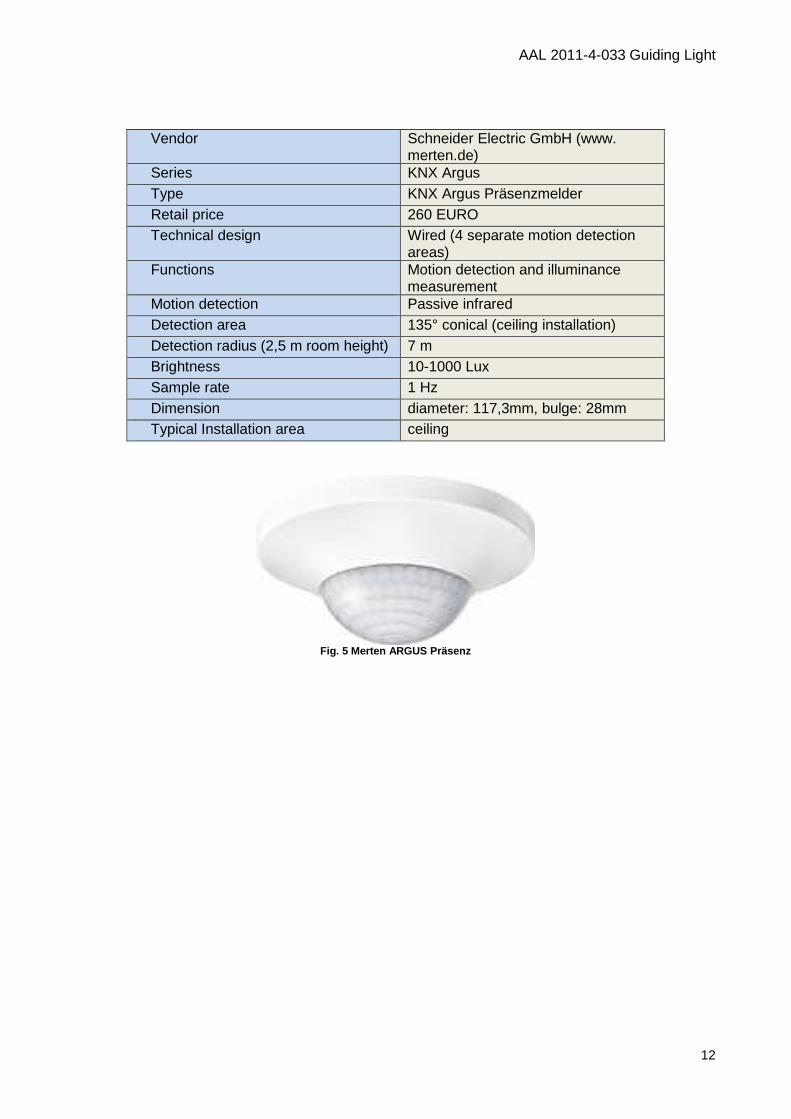
2.3.2. Passive infrared (PIR) sensor with Luxmeter The wired GL-solution utilizes a PIR sensor for motion detection which is able to detect motion in 4 separate sectors. Moreover, this sensor measures brightness values up to 1000 lux within it’s the detection range. This kind of PIR sensor has the following advantages and disadvantages: Advantage: A room can be divided into separate quadrants for activity monitoring by utilizing only one sensor placed on the ceiling in the middle of the room. On the specific turning of the PIR sensor, motion detection within the four quadrants can be assigned to four specific room zones. Disadvantages: Depending on the location of the moving person, up to 4 sectors of the PIR sensor simultaneously transmit a movement signal. Thus, a zonally activity monitoring in the room periphery is more precise and accurate than in the centre of the room. In addition, since the detection zones of the PIR sensor are not adjustable, the installation of an additional PIR sensor is necessary for movement detection in small areas (for example the kitchen area). Since the sensor needs a direct wiring to the home automation system, it can only be placed in locations where the power supply and the connection to a home bus system are available. In the following table, the technical specification of the PIR sensor is described:
AAL 2011-4-033 Guiding Light
12
Vendor Schneider Electric GmbH (www.
merten.de) Series KNX Argus Type KNX Argus Präsenzmelder Retail price 260 EURO Technical design Wired (4 separate motion detection
areas) Functions Motion detection and illuminance
measurement Motion detection Passive infrared Detection area 135° conical (ceiling installation) Detection radius (2,5 m room height) 7 m Brightness 10-1000 Lux Sample rate 1 Hz Dimension diameter: 117,3mm, bulge: 28mm Typical Installation area ceiling
Fig. 5 Merten ARGUS Präsenz
AAL 2011-4-033 Guiding Light
13
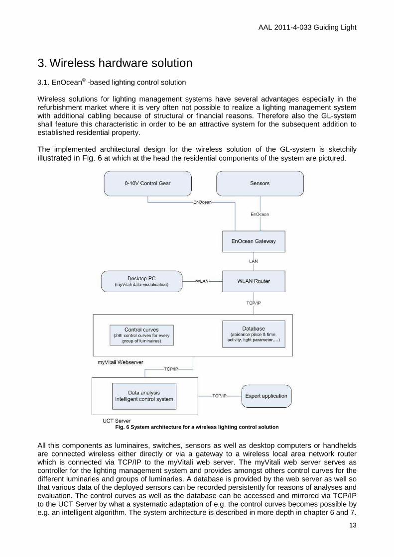
3. Wireless hardware solution 3.1. EnOcean© -based lighting control solution Wireless solutions for lighting management systems have several advantages especially in the refurbishment market where it is very often not possible to realize a lighting management system with additional cabling because of structural or financial reasons. Therefore also the GL-system shall feature this characteristic in order to be an attractive system for the subsequent addition to established residential property. The implemented architectural design for the wireless solution of the GL-system is sketchily illustrated in Fig. 6 at which at the head the residential components of the system are pictured.
Fig. 6 System architecture for a wireless lighting control solution
All this components as luminaires, switches, sensors as well as desktop computers or handhelds are connected wireless either directly or via a gateway to a wireless local area network router which is connected via TCP/IP to the myVitali web server. The myVitali web server serves as controller for the lighting management system and provides amongst others control curves for the different luminaries and groups of luminaries. A database is provided by the web server as well so that various data of the deployed sensors can be recorded persistently for reasons of analyses and evaluation. The control curves as well as the database can be accessed and mirrored via TCP/IP to the UCT Server by what a systematic adaptation of e.g. the control curves becomes possible by e.g. an intelligent algorithm. The system architecture is described in more depth in chapter 6 and 7.
AAL 2011-4-033 Guiding Light
14
For the link-up of the residential components in the field layer to the cloud based controller the out of the box solutions of the EnOcean Alliance are used for reasons already described in Deliverable 6.1 “Report on Market Analyses”. Nevertheless we will give a brief overview
• EnOcean products are installed in over 200000 buildings worldwide with huge acceptance, product reliability and a forecast of market share of up to 5.5% of the global GDP growth within the next five years whereby the backing of EnOcean products is secured by the commercial companies of the EnOcean Alliance although it is only a proprietary standard.
• EnOcean is well suited for applications within the area of private home automation since a sufficient selection of wireless transceiver modules, repeaters and gateways is available commercially for out of the box solutions.
• Self-powered devices such as switches or sensors with energy harvesting capability exist. Self-powered EnOcean devices are build on low power by what periodic maintenance becomes needless. Switches have good reliability.
• A member of the consortium, MyVitali, is also a member of the EnOcean Alliance and can manifest great experience with the EnOcean technology.
Despite the advantages of the EnOcean technology there are also some major disadvantages which rely occasionally on the basic topological concepts, the used frequency range for transmission and the availability of EnOcean to DALI Gateways. Nevertheless, EnOcean technology fulfils all requirements that arise from the Guiding Light project at this point in time.
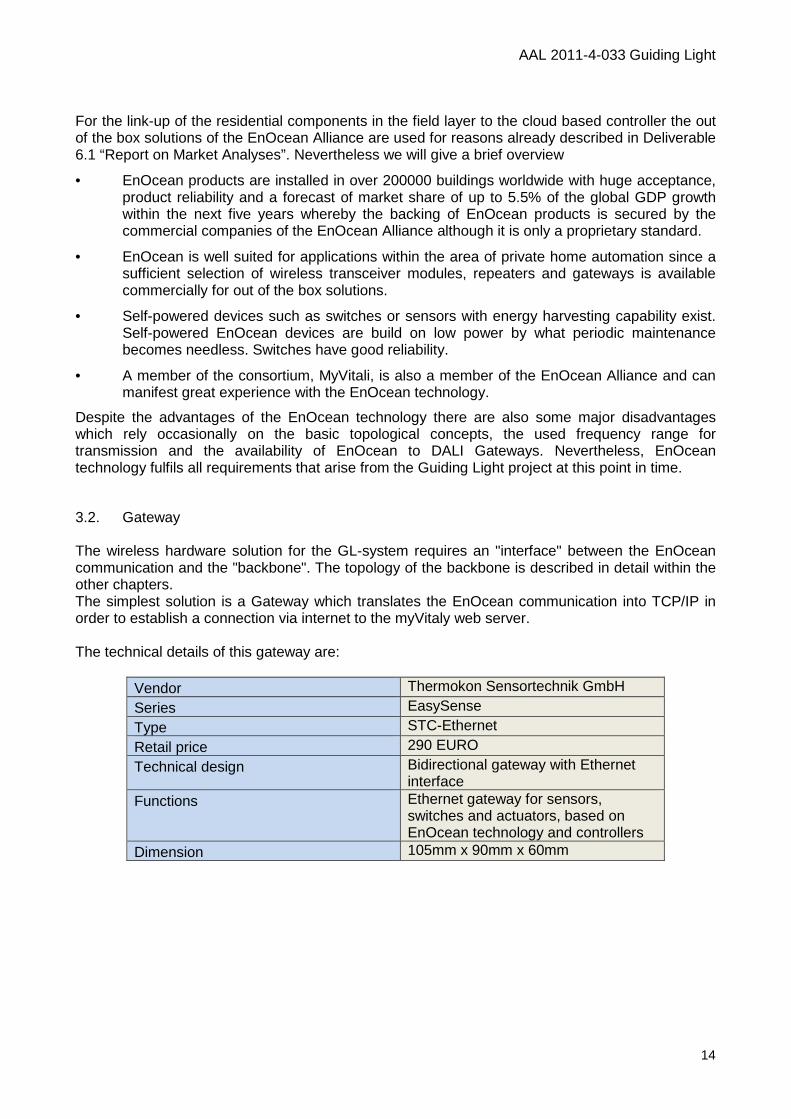
3.2. Gateway The wireless hardware solution for the GL-system requires an "interface" between the EnOcean communication and the "backbone". The topology of the backbone is described in detail within the other chapters. The simplest solution is a Gateway which translates the EnOcean communication into TCP/IP in order to establish a connection via internet to the myVitaly web server. The technical details of this gateway are:
Vendor Thermokon Sensortechnik GmbH
Series EasySense
Type STC-Ethernet
Retail price 290 EURO
Technical design Bidirectional gateway with Ethernet interface
Functions Ethernet gateway for sensors, switches and actuators, based on EnOcean technology and controllers
Dimension 105mm x 90mm x 60mm
AAL 2011-4-033 Guiding Light
15
Fig. 7 Thermokon STC-Ethernet gateway
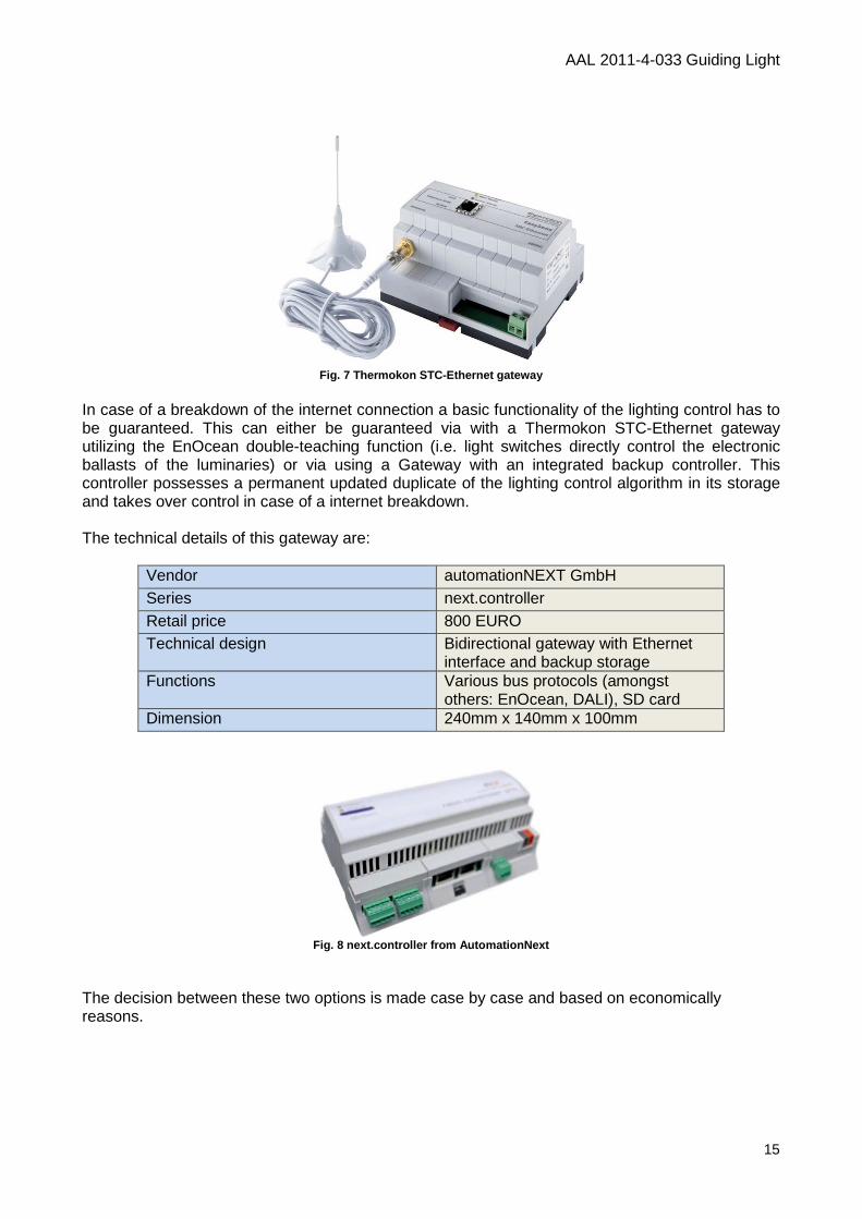
In case of a breakdown of the internet connection a basic functionality of the lighting control has to be guaranteed. This can either be guaranteed via with a Thermokon STC-Ethernet gateway utilizing the EnOcean double-teaching function (i.e. light switches directly control the electronic ballasts of the luminaries) or via using a Gateway with an integrated backup controller. This controller possesses a permanent updated duplicate of the lighting control algorithm in its storage and takes over control in case of a internet breakdown. The technical details of this gateway are:
Vendor automationNEXT GmbH Series next.controller Retail price 800 EURO Technical design Bidirectional gateway with Ethernet
interface and backup storage Functions Various bus protocols (amongst
others: EnOcean, DALI), SD card Dimension 240mm x 140mm x 100mm
Fig. 8 next.controller from AutomationNext
The decision between these two options is made case by case and based on economically reasons.
AAL 2011-4-033 Guiding Light
16
3.3. Actors 3.3.1. Lighting control (electronic ballast) Currently, there is no LED driver with integrated EnOcean radio module available on the market. As a consequence the controlling of the two light colours in each luminaire causes the installation of at least two "addresses" per luminaire. This is currently realized by adding EnOcean actors (in the following called "Eltako control devices") to the electronic ballast. These additional devices are integrated into or onto the luminaire casing according to luminaire constructions. In the near future (Q1/2014) LED drivers with integrated EnOcean radio modules will be available on the commercial market (e.g. www.bilton.at). Currently EnOcean transmitting will be done by Eltako control devices with the following technical specification:
Vendor Eltako Electronics Series Control device Type FSG70/1-10V Retail price 90 EURO Technical design Enocean,
1-10V lighting control protocol Functions Dimming, switching, programmable Dimension 100mm x 50mm x 25mm
Therefore currently the luminaries must be equipped with 1-10V ballasts. The manufacturer of the Guiding Light luminaires (company "Projektleuchten") is using the following electronic ballast:
Vendor TCI Series Jolly Slim 1...10V & PUSH Type DC Jolly Slim 24W, 500mA Retail price 28 EURO Technical design Power supply 230V, 50Hz,
LED driver in constant current technology Functions 1...10V & PUSH Dimension 207mm x 42mm x 31mm
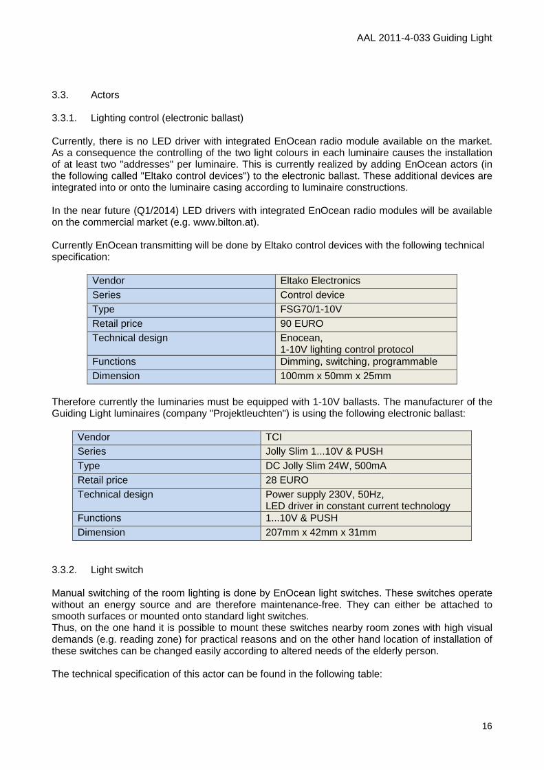
3.3.2. Light switch Manual switching of the room lighting is done by EnOcean light switches. These switches operate without an energy source and are therefore maintenance-free. They can either be attached to smooth surfaces or mounted onto standard light switches. Thus, on the one hand it is possible to mount these switches nearby room zones with high visual demands (e.g. reading zone) for practical reasons and on the other hand location of installation of these switches can be changed easily according to altered needs of the elderly person. The technical specification of this actor can be found in the following table:
AAL 2011-4-033 Guiding Light
17
Vendor Eltako Electronics Series Wireless push button Type FT4F Retail price 40 EURO Technical design Wireless - Enocean
(ISO/IEC 14543-3-10) Functions Switching Dimension Button size: 80 x 80 mm;
inside frame size: 63 x 63 mm; thickness 15mm
3.4. Sensors For automatic room lighting control and activity monitoring of the elderly within their homes wireless PIR sensors and a door contact sensor are used. 3.4.1. Door contact sensor For a proper functioning of the room lighting control and an accurate recording of the activity of the elderly person, it is necessary to clearly identify periods during which no one is at home. This information will be derived from data of the front-door mounted contact sensor and the PIR sensors installed in each room. By means of these data the probability of presence within the apartment can be determined. In the following the advantages and disadvantages of the usage of this sensor are summarized:
advantages disadvantages
low costs
presence detection possible with additional PIR sensor data (details regarding the
algorithm are described in D2.2 "Applicable Software Components").
ease of installation (due to its wireless functionality)
No need for maintenance (due to its independency from any power source)
Flexible positioning (can be attached anywhere on the side or top of a door)
small form factor removal any time possible
The technical specifications of the door contact sensor are:
AAL 2011-4-033 Guiding Light
18
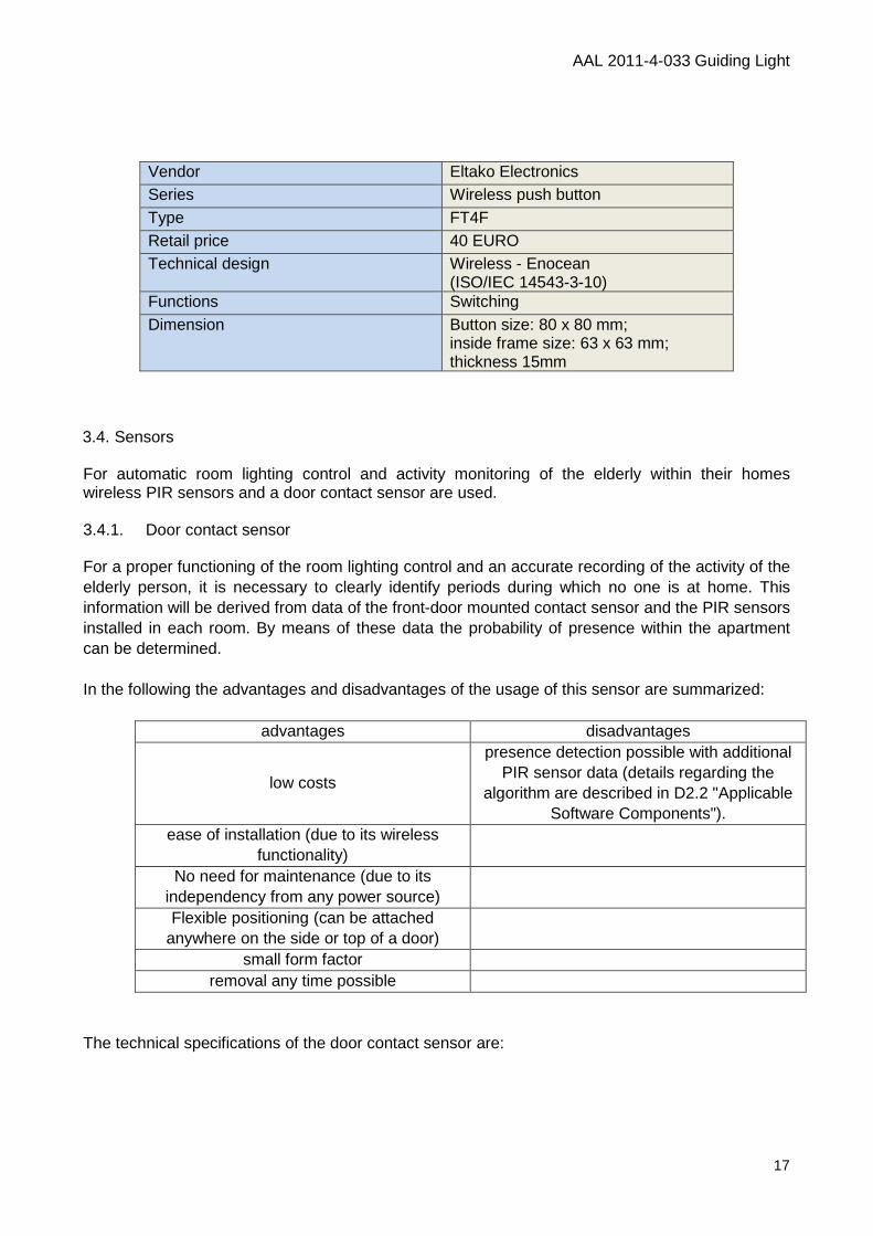
Vendor Thermokon Sensortechnik GmbH (www.thermokon.de)
Series Relais Type FK Retail price 60 EURO Technical design Wireless Wireless technology EnOcean (ISO/IEC 14543-3-10) Radio frequency 868,3 MHz Functions Switching through reedrelais and
magnet Power source Solar panel Dimension 54mm x 12mm x 10mm
Fig. 9 EnOcean door contact sensor
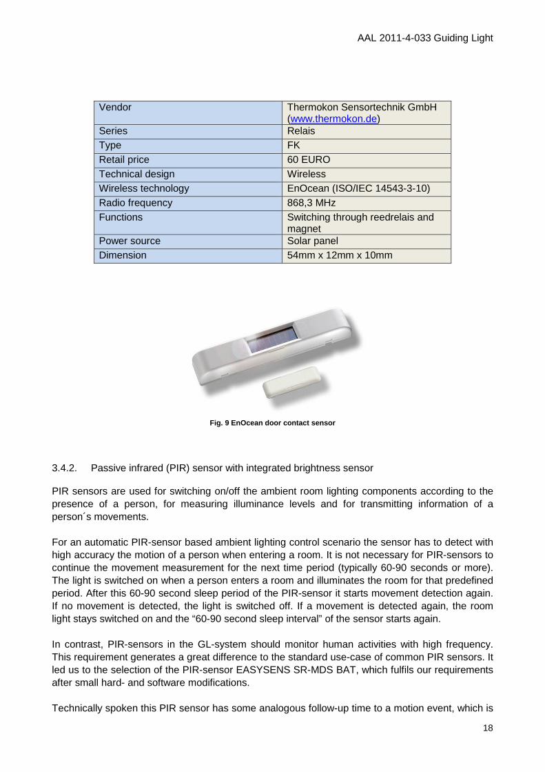
3.4.2. Passive infrared (PIR) sensor with integrated brightness sensor PIR sensors are used for switching on/off the ambient room lighting components according to the presence of a person, for measuring illuminance levels and for transmitting information of a person´s movements. For an automatic PIR-sensor based ambient lighting control scenario the sensor has to detect with high accuracy the motion of a person when entering a room. It is not necessary for PIR-sensors to continue the movement measurement for the next time period (typically 60-90 seconds or more). The light is switched on when a person enters a room and illuminates the room for that predefined period. After this 60-90 second sleep period of the PIR-sensor it starts movement detection again. If no movement is detected, the light is switched off. If a movement is detected again, the room light stays switched on and the “60-90 second sleep interval” of the sensor starts again. In contrast, PIR-sensors in the GL-system should monitor human activities with high frequency. This requirement generates a great difference to the standard use-case of common PIR sensors. It led us to the selection of the PIR-sensor EASYSENS SR-MDS BAT, which fulfils our requirements after small hard- and software modifications. Technically spoken this PIR sensor has some analogous follow-up time to a motion event, which is
AAL 2011-4-033 Guiding Light
19
based on the technical specifications of the applied capacitor and resistor circuit. The vendor Thermokon specifically modified the PIR-sensor EASYSENS SR-MDS BAT (changes included software and hardware modifications) to have shorter reaction times for motion detection. The changes should now make a new event trigger possible after 5 seconds.
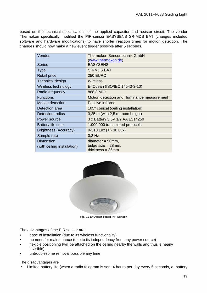
Vendor Thermokon Sensortechnik GmbH (www.thermokon.de)
Series EASYSENS Type SR-MDS BAT Retail price 250 EURO Technical design Wireless Wireless technology EnOcean (ISO/IEC 14543-3-10) Radio frequency 868,3 MHz Functions Motion detection and illuminance measurement Motion detection Passive infrared Detection area 105° conical (ceiling installation) Detection radius 3,25 m (with 2,5 m room height) Power source 3 x Battery 3,6V 1/2 AA LS14250 Battery life time 1.000.000 transmitted protocols Brightness (Accuracy) 0-510 Lux (+/- 30 Lux) Sample rate 0,2 Hz Dimension (with ceiling installation)
diameter = 90mm, bulge size = 28mm, thickness = 35mm
Fig. 10 EnOcean-based PIR-Sensor
The advantages of the PIR sensor are • ease of installation (due to its wireless functionality) • no need for maintenance (due to its independency from any power source) • flexible positioning (will be attached on the ceiling nearby the walls and thus is nearly
invisible) • untroublesome removal possible any time The disadvantages are • Limited battery life (when a radio telegram is sent 4 hours per day every 5 seconds, a battery
AAL 2011-4-033 Guiding Light
20
change is required after 347 days) • Limitation of the detection range is only possible through a special spatial attachment (ie
shading walls or tilted mounting)
4. Lighting Solution 4.1. Lighting Concept In the framework of workpackage "WP2 - Intelligent room technologies" several lighting concepts were analyzed. The decision making process is documented in deliverable "D2.1 Applicable hardware components". The presented deliverable focuses on the final Guiding Light solution. The development of the GL-system bases on the following four lighting design principles: Each room (bedroom, bathroom, and living room) has an ambient room lighting component which ensures a very uniform illumination of the transit zones (up to 300 lux horizontal illuminance at the floor). For economic reasons artificial light complements the amount of indoor daylight during the day (this will be made possible via brightness measurement of the PIR sensors). For the age-specific illumination of areas with increased visual demands a special task lighting which creates a glare-free illumination with up to 2000 lux, will be installed. The light color of all lamps changes gradually from 2200 Kelvin to 4000 Kelvin during the day according to the individual sleep-wake time of the elderly. Because older people are very sensitive to glare, the maximum ambient luminance is restricted to 1000 cd/m². 4.2. Luminaires A survey of commercial available luminaries’ components showed that there are 23 products of 13 manufacturers available on the market which could fulfil some requirements for an age-specific lighting system. Up to now there exists no luminaire on the market which fulfil all our requirements together. Therefore a new luminaire portfolio was developed by BLL and prototypes were manufactured by luminaire producer "Projektleuchten GmbH". A portfolio of six luminaries (two for ambient and four for task lighting purposes) is necessary to realize the lighting concept. The photometrical specifications of these luminaires are listed in the following tables:
Ambient light 1 Manufacturer
Luminaire label
Assembly (LED-Typ / Binning / Cat- Code)
Dimension (length x height)
Luminaire Luminous flux / luminous efficiency
Electrical ballast
Electrical parameters
CCT / CRI / chromaticity coordinate
Luminaire photo
LID polar false colour visualization [cd/klm]
AAL 2011
Projektleuchten (www.projektleuchten.de
Suspended living room light
Code) 50 x CREE XT-E 2200K, 50 x CREE XT
600 mm x 54 mm
Luminous flux / luminous efficiency 12078 lm 69 lm/W
depending on choice of wired or wireless solution
500 mA 175 W
2200/5700 K 81/88
Spectrum
LID polar false colour visualization [cd/klm] LID cartesian diagram [cd/klm]
50
100
150
200
250
300
50
100
150
200
250
300
cd/klmC0 - C180 C90 - C270
90.0° 67.5° 45.0° 22.5° 0.0° 22.5°
AAL 2011-4-033 Guiding Light
21
www.projektleuchten.de)
E 2200K, 50 x CREE XT-E 5700K
69 lm/W
depending on choice of wired or wireless solution
100%
22.5° 45.0° 67.5° 90.0°
Ambient light 2 Manufacturer
Luminaire label
Assembly (LED-Typ / Binning / Cat- Code)
Dimension (length x width x height)
Luminaire Luminous flux / luminous efficiency
Electrical ballast
Electriacl parameters
CCT / CRI
Luminaire photo
LID polar false colour visualization [cd/klm]
AAL 2011
Projektleuchten (www.projektleuchten.de
Ceiling Washer
Code) 9 x CREE XT-E 2200K, 9 x CREE XT
500 mm x 48 mm x 65 mm
Luminous flux / luminous efficiency 1685 lm 33 lm/W
depending on choice of wired or wireless solution
500 mA 33 W
2200/5700 K 81/88
Spectrum
LID polar false colour visualization [cd/klm] LID cartesian diagram [cd/klm]
200
400
600
800
1000
200
400
600
800
1000
cd/klmC0 - C180 C30 - C210 C60 - C240
90.0° 67.5° 45.0° 22.5° 0.0° 22.5°
AAL 2011-4-033 Guiding Light
22
www.projektleuchten.de)
E 2200K, 9 x CREE XT-E 5700K
33 lm/W
choice of wired or wireless solution
100%
C60 - C240 C90 - C270
22.5° 45.0° 67.5° 90.0°
Task light 1 Manufacturer
Luminaire label
Assembly (LED-Typ / Binning / Cat- Code)
Dimension (Length x Width x Height)
Luminaire Luminous flux / luminous efficiency
Electrical ballast
Electrical parameters
CCT / CRI
Luminaire photo
LID polar false colour visualization [cd/klm]
AAL 2011
Projektleuchten (www.projektleuchten.de
Suspended living room task light
Code) 12 x CREE XT-E 2200K, 12 x CREE XT
600 mm x 54 mm
Luminous flux / luminous efficiency 2825 lm 64 lm/W
depending on choice of wired or wireless solution
500 mA 44 W
2200/5700 K 81/88
Spectrum
polar false colour visualization [cd/klm] LID cartesian diagram [cd/klm]
200
400
600
800
1000
1200
200
400
600
800
1000
1200
cd/klmC0 - C180 C90 - C270
90.0° 67.5° 45.0° 22.5° 0.0° 22.5°
AAL 2011-4-033 Guiding Light
23
www.projektleuchten.de)
E 2200K, 12 x CREE XT-E 5700K
64 lm/W
depending on choice of wired or wireless solution
100%
22.5° 45.0° 67.5° 90.0°
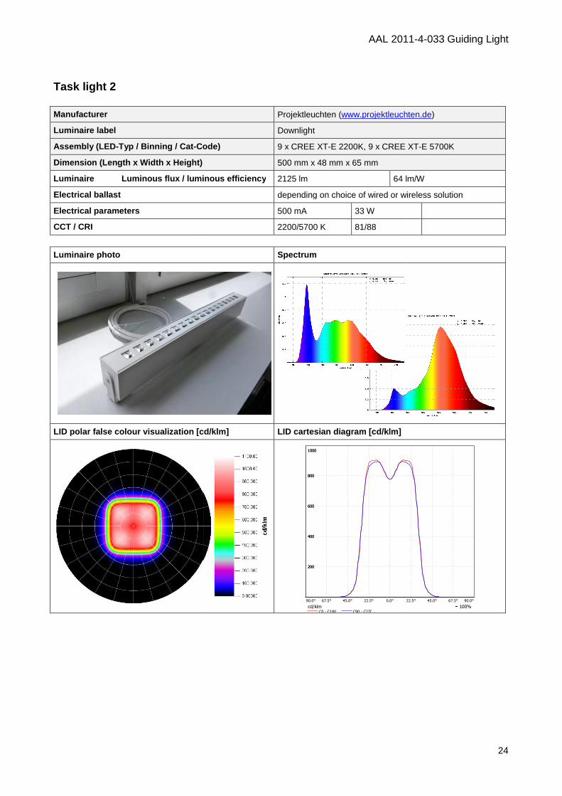
Task light 2 Manufacturer
Luminaire label
Assembly (LED-Typ / Binning / Cat- Code)
Dimension (Length x Width x Height)
Luminaire Luminous flux / luminous efficiency
Electrical ballast
Electrical parameters
CCT / CRI
Luminaire photo
LID polar false colour visualization [cd/klm]
AAL 2011
Projektleuchten (www.projektleuchten.de
Downlight
Code) 9 x CREE XT-E 2200K, 9 x CREE XT
500 mm x 48 mm x 65 mm
Luminous flux / luminous efficiency 2125 lm 64 lm/W
depending on choice of wired or wireless
500 mA 33 W
2200/5700 K 81/88
Spectrum
LID polar false colour visualization [cd/klm] LID cartesian diagram [cd/klm]
200
400
600
800
1000
200
400
600
800
1000
cd/klmC0 - C180 C90 - C270
90.0° 67.5° 45.0° 22.5° 0.0° 22.5°
AAL 2011-4-033 Guiding Light
24
www.projektleuchten.de)
E 2200K, 9 x CREE XT-E 5700K
64 lm/W
depending on choice of wired or wireless solution
100%
22.5° 45.0° 67.5° 90.0°
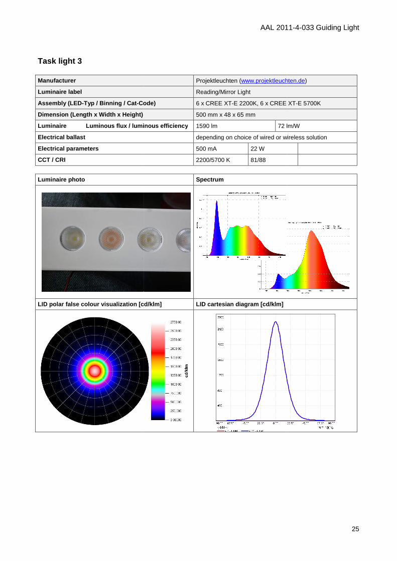
Task light 3 Manufacturer
Luminaire label
Assembly (LED-Typ / Binning / Cat- Code)
Dimension (Length x Width x Height)
Luminaire Luminous flux / luminous efficiency
Electrical ballast
Electrical parameters
CCT / CRI
Luminaire photo
LID polar false colour visualization [cd/klm]
AAL 2011
Projektleuchten (www.projektleuchten.de
Reading/Mirror Light
Code) 6 x CREE XT-E 2200K, 6 x CREE XT
500 mm x 48 x 65 mm
Luminous flux / luminous efficiency 1590 lm 72 lm/W
depending on choice of wired or wireless solution
500 mA 22 W
2200/5700 K 81/88
Spectrum
visualization [cd/klm] LID cartesian diagram [cd/klm]
AAL 2011-4-033 Guiding Light
25
www.projektleuchten.de)
E 2200K, 6 x CREE XT-E 5700K
72 lm/W
depending on choice of wired or wireless solution
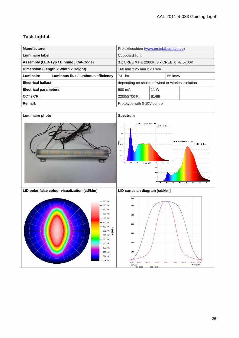
Task light 4 Manufacturer
Luminaire label
Assembly (LED-Typ / Binning / Cat- Code)
Dimension (Length x Width x Height)
Luminaire Luminous flux / luminous efficiency
Electrical ballast
Electrical parameters
CCT / CRI
Remark
Luminaire photo
LID polar false colour visualization [cd/klm]
AAL 2011
Projektleuchten (www.projektleuchten.de
Cupboard light
Code) 3 x CREE XT-E 2200K, 3 x CREE XT
160 mm x 25 mm x 20 mm
Luminous flux / luminous efficiency 731 lm 66 lm/W
depending on choice of wired or wireless solution
500 mA 11 W
2200/5700 K 81/88
Prototype with 0-10V control
Spectrum
LID polar false colour visualization [cd/klm] LID cartesian diagram [cd/klm]
100
200
300
400
500
600
700
100
200
300
400
500
600
700
cd/klmC0 - C180 C90 - C270
90.0° 67.5° 45.0° 22.5° 0.0° 22.5°
AAL 2011-4-033 Guiding Light
26
www.projektleuchten.de)
E 2200K, 3 x CREE XT-E 5700K
66 lm/W
depending on choice of wired or wireless solution
100%
22.5° 45.0° 67.5° 90.0°
AAL 2011-4-033 Guiding Light
27
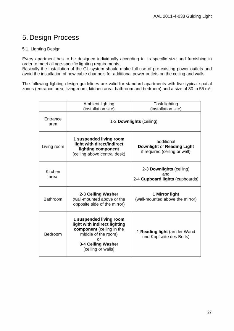
5. Design Process 5.1. Lighting Design Every apartment has to be designed individually according to its specific size and furnishing in order to meet all age-specific lighting requirements. Basically the installation of the GL-system should make full use of pre-existing power outlets and avoid the installation of new cable channels for additional power outlets on the ceiling and walls. The following lighting design guidelines are valid for standard apartments with five typical spatial zones (entrance area, living room, kitchen area, bathroom and bedroom) and a size of 30 to 55 m²:
Ambient lighting (installation site)
Task lighting (installation site)
Entrance
area
1-2 Downlights (ceiling)
Living room
1 suspended living room light with direct/indirect
lighting component (ceiling above central desk)
additional Downlight or Reading Light
if required (ceiling or wall)
Kitchen area
2-3 Downlights (ceiling)
and 2-4 Cupboard lights (cupboards)
Bathroom
2-3 Ceiling Washer
(wall-mounted above or the opposite side of the mirror)
1 Mirror light (wall-mounted above the mirror)
Bedroom
1 suspended living room light with indirect lighting component (ceiling in the
middle of the room) or
3-4 Ceiling Washer (ceiling or walls)
1 Reading light (an der Wand und Kopfseite des Betts)
AAL 2011-4-033 Guiding Light
28
5.2. Sensor Design
5.2.1. Installation of PIR sensors The attachment of cable-based PIR sensors is primarily restricted to places where the wiring to the home automation system already exists. An installation of additional wirings is rather complicated and expensive. In contrast, the placement in wireless PIR sensors is possible on all smooth surfaces. Basically, all PIR sensors should be fixed on the ceiling. In addition, the installation location of the sensor is to be selected as the edge of the ceiling and in the vicinity of the walls. Consequently detection range of the PIR sensor is limited by means of the ceiling and the adjacent walls and the visibility of the PIR sensor is greatly reduced. For the reliable detection of a person´s room change (this information is needed to automatically turn on the ambient lighting component when the room is entered) a PIR sensor has to be mounted nearby the door on the ceiling. This sensor placement has the advantage, that the elderly person must pass through the detection range of the PIR sensor orthogonally and thus the probability of sending a movement signal by the PIR sensor is significantly increased. On the other hand the visibility of the PIR sensor is significantly reduced by such a sensor placement. Finally, the manufacturer of PIR sensor recommends attachment of the sensor at a certain distance from luminaries and windows (to avoid interference from operating equipment and radiated heat of the lamp, and to detect movement of outside passers-by misleadingly). As a rule of thumb an average of 6 to 7 PIR sensors is needed per apartment:
Room presence detection Zonal detection
Entrance Area
Nearby entrance door
Living room
Nearby entrance door
“ZONES with higher presence probability” (e.g. reading chair, TV
zone) (tilted) above specific zones
Kitchen
Area
“KITCHEN-ZONE”: Above Cupboards
Bathroom
Nearby the entrance door
Bedroom
Nearby the entrance door “BED-ZONE”:
Wall-mounted or under the bed
AAL 2011-4-033 Guiding Light
29
5.2.2. Installation place of door contact sensor An attached wireless door contact sensor is hardly seen because of its small size and can be easily be removed at any time (e.g. via usage of a double-sided tape for the attachment of the sensor). The installation of the wired door barrier switch is more complex, expensive and invasive and the installation instruction must be followed strictly. 5.3. Actor installation procedure 5.3.1. Installation of the light switches For the wired Guiding Light solution package, the existing light switches have to be used. The wireless Guiding Light solution allows a manual operation of the task lighting within these task zones (by the aid of a freely placeable light switch). The attachment of the light switches with double-sided tape only needs a smooth surface and can be changed at any time without nearly an effort. Additionally, the existing light switches for the ambient lighting components will be replaced by wireless light switches within the wireless GL-system.
6. Lighting control 6.1. Lighting control scheme Basically, ambient room lighting components are switched automatically in case of the presence of a person and subject to the amount of daylight entering the room. For the control of the task lighting components in spatial zones with increased visual needs two control strategies have been developed: Strategy 1: task lighting must be switched manually Strategy 2: task lighting is automatically switched on and off depending on the time of day. Thus task lighting control takes place independently of the presence of the person in this task area. A detailed description of the core intentions of these two lighting control strategies can be found in chapter 6.3.
AAL 2011-4-033 Guiding Light
30
6.2. Presence-oriented control of ambient lighting components
PIR sensors detect changes in motion of objects radiating heat. Consequently a special algorithm has to determine the probability of room occupancy on the basis of recently transmitted PIR sensor data. In the absence of movement no PIR signal is sent and occupancy must be deduced from the last PIR signals (“extrapolation of last occupancy”). By means of this measure an automatic switching off the ambient light component should be avoided. In case of changing rooms it may happen that two rooms´ PIR signals are sent simultaneously. Consequently the room occupancy cannot be determined for a certain time period (for instance up to 15 seconds) and therefore the ambient lighting components of both rooms are switched on. After this time period, a clear assignment of a person´s presence based of the incoming PIR signals should again be possible and accordingly ambient room lights are switched off in the unoccupied space. Furthermore, prevailing indoor illuminance levels can be determined from the last measured illuminance values of the PIR sensor. Thus, the ambient artificial lighting component can be dimmed accordingly in order to meet the requirement for ambient lighting. Brightness levels of the ambient lighting components can be changed at any time via associated light switches. This change will remain as long as the person is located in the corresponding room. If the person leaves the room and comes back later, the ambient room lighting is automatically switched on again. In case of the transmission of the door contact sensor (i.e. the door was opened/closed) and the lack of transmission of PIR signals indicating the lack of indoor motion of a person over a certain amount of time (e.g. 5 minutes), this signal combination is interpreted as the absence of a person in the apartment and the ambient lighting components are turned off. A light switch within reach of the bed basically allows the manual switching of the bedroom lighting during the night hours. As a consequence, the ambient lighting component in the bedroom should be turned off manually by the older person. In case of nocturnal toileting assistance by ambient lighting an additional sensor is required to accurately detect the stay in bed of the older person. This sensor can either be a pressure sensor integrated in the mattress or a PIR sensor, which is mounted under or above the bed. In addition, information on the typical times in bed over the last four weeks is used to establish an individual lighting control algorithm for the ambient lighting components which both varies the light intensity and color temperature of the lighting depending on individual sleep-/wake rhythm. In case of the presence of a person the room is illuminated very homogeneous with 300 lux and 4000 Kelvin at floor level between getting up and 2,5 hours before going to bed again. Within the next half hour color temperature of the ambient light is reduced from 4000 Kelvin to 2200 Kelvin and the illuminance level is dimmed imperceptibly from 300 lux to 150 lux. Within the two hours of going to bed illuminance levels are further linearly reduced to 50 lux. When the bed is left during the nighttimes rooms are illuminated with a maximum of 50 lux and a color temperature of 2200 Kelvin. Individual adaptation to lower brightness during nighttimes hours is possible on request of the older person. A special optional feature of the general lighting components in the bedroom is to simulate an artificial dawn for ease of waking up and getting up. This light alarm clock function exponentially
AAL 2011-4-033 Guiding Light
31
increases room brightness from 0 to 300 lux, starting half an hour before intended awakening and changing color temperature from 5700 Kelvin to 4000 Kelvin. To sum up, ambient lighting should support - the visual needs for spatial orientation, safe navigation and strainless visual information
processing and - the non-visual needs for temporal orientation, stable sleep-/wake rhythm, vigilance and bright
mood by means of a individualized lighting control scheme. 6.3. Control of task lighting components
Basically task lighting should always be adapted to the individual visual needs of the older person. All task lighting luminaries can potentially be operated between 500 lux and 2000 lux at task level. Utilizing a standardized visual performance test (Mars contrast sensitivity test – http://www.marsperceptrix.com/) in advance under standardized indoor lighting conditions (without daylight entering the room and the ambient room lighting components switched on) the individual optimal brightness level for all working areas are determined. Generally 1000 lux at task level is set as predefined brightness level for zonal lighting during the day. 6.3.1. Lighting control scheme to fulfil visual needs (Strategy 1) This light control strategy is based on an exclusive manual operation of the task lighting luminaries. For a comfortable and frequent use of the task lights, the corresponding light switches are mounted within reach of the tasks. From getting out of bed to 2.5 hours before going to bed again task lighting is switched on manually and a predefined optimal brightness level with 4000 Kelvin illuminate the task areas. Over the subsequent half hour task lighting is changed indiscernibly in color temperature from 4000 Kelvin to 2200 Kelvin and the optimal daytime brightness is dimmed to a third. This setting of the zonally lighting remains during the evening and night. Again brightness levels of the task lighting components can be further reduced at the request of the older person during nighttimes. 6.3.2. Lighting control scheme to support temporal orientation (Strategy 2) The aim of Guiding Light is to improve mobility of older persons by means of behaviour-modifying light interventions. For this purpose we have to define in which room zones of apartment inhabitants typically stay during a day. With the information about what they are typically doing within this room zones at a specific time of day we can illuminate this room zones with adequate lighting parameters. This kind of dynamic light will be pre-programmed according to the individual daily structure of an inhabitant. Such pre-programming includes time-controlled parameters of light intensity and light colour temperatures as well as commands for switching on and switching off light. The following picture illustrates an example: At half past one an inhabitant is detected within an apartment. At half past two Guiding Light starts illuminating a room zone, where inhabitant typically
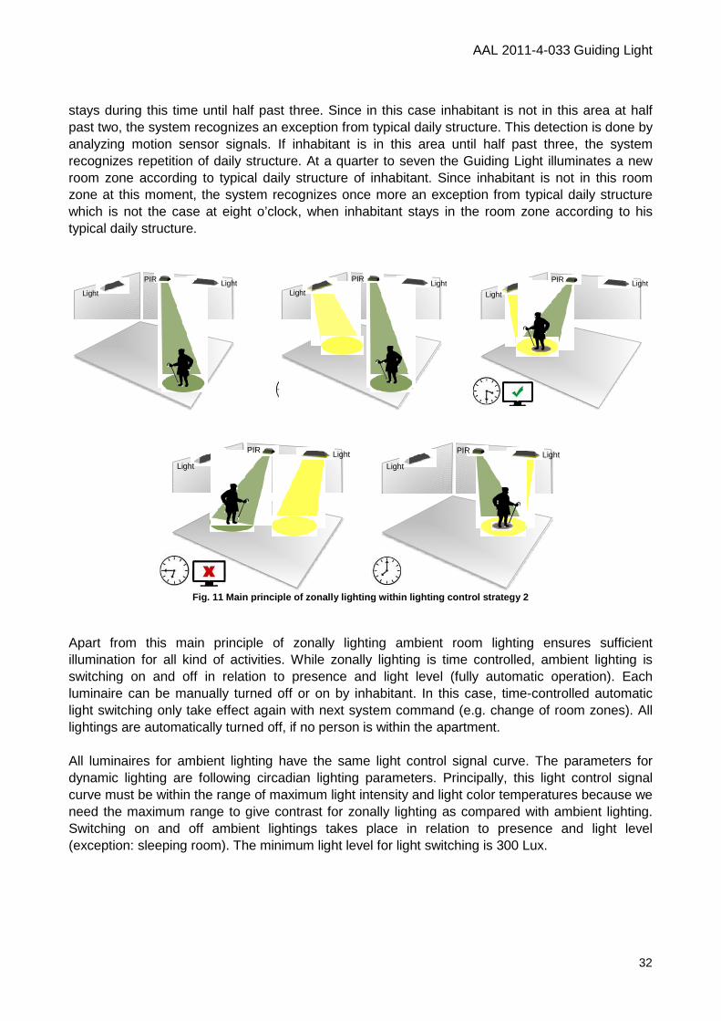
AAL 2011-4-033 Guiding Light
32
stays during this time until half past three. Since in this case inhabitant is not in this area at half past two, the system recognizes an exception from typical daily structure. This detection is done by analyzing motion sensor signals. If inhabitant is in this area until half past three, the system recognizes repetition of daily structure. At a quarter to seven the Guiding Light illuminates a new room zone according to typical daily structure of inhabitant. Since inhabitant is not in this room zone at this moment, the system recognizes once more an exception from typical daily structure which is not the case at eight o’clock, when inhabitant stays in the room zone according to his typical daily structure.
Fig. 11 Main principle of zonally lighting within l ighting control strategy 2
Apart from this main principle of zonally lighting ambient room lighting ensures sufficient illumination for all kind of activities. While zonally lighting is time controlled, ambient lighting is switching on and off in relation to presence and light level (fully automatic operation). Each luminaire can be manually turned off or on by inhabitant. In this case, time-controlled automatic light switching only take effect again with next system command (e.g. change of room zones). All lightings are automatically turned off, if no person is within the apartment. All luminaires for ambient lighting have the same light control signal curve. The parameters for dynamic lighting are following circadian lighting parameters. Principally, this light control signal curve must be within the range of maximum light intensity and light color temperatures because we need the maximum range to give contrast for zonally lighting as compared with ambient lighting. Switching on and off ambient lightings takes place in relation to presence and light level (exception: sleeping room). The minimum light level for light switching is 300 Lux.
PIR
Light Light PIR
Light Light PIR
Light
Light
PIR
Light Light
PIR
Light Light
AAL 2011-4-033 Guiding Light
33
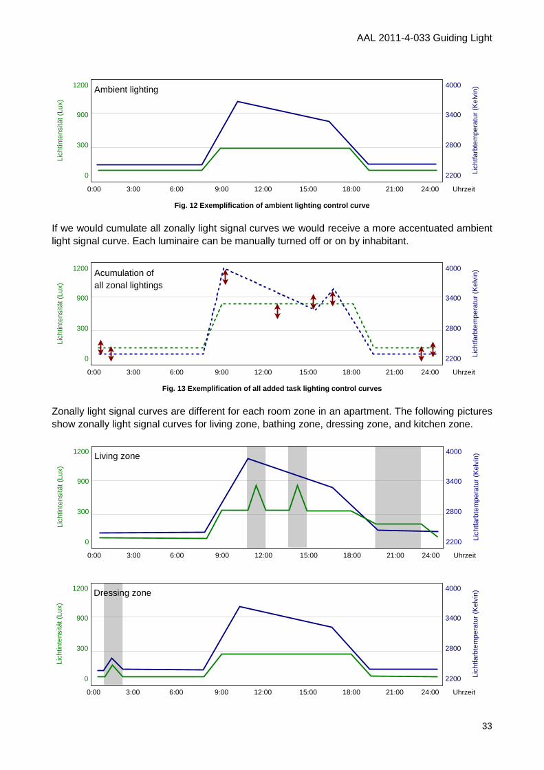
Fig. 12 Exemplification of ambient lighting control curve
If we would cumulate all zonally light signal curves we would receive a more accentuated ambient light signal curve. Each luminaire can be manually turned off or on by inhabitant.
Fig. 13 Exemplification of all added task lighting control curves
Zonally light signal curves are different for each room zone in an apartment. The following pictures show zonally light signal curves for living zone, bathing zone, dressing zone, and kitchen zone.
1200
900
300
0
4000
3400
2800
2200
Lich
tinte
nsitä
t (Lu
x)
Lich
tfarb
tem
pera
tur
(Kel
vin)
0:00 3:00 6:00 9:00 12:00 15:00 18:00 21:00 24:00 Uhrzeit
Ambient lighting
1200
900
300
0
4000
3400
2800
2200
Lich
tinte
nsitä
t (Lu
x)
Lich
tfarb
tem
pera
tur
(Kel
vin)
0:00 3:00 6:00 9:00 12:00 15:00 18:00 21:00 24:00 Uhrzeit
Acumulation ofall zonal lightings
1200
900
300
0
4000
3400
2800
2200
Lich
tinte
nsitä
t (Lu
x)
Lich
tfarb
tem
pera
tur
(Kel
vin)
0:00 3:00 6:00 9:00 12:00 15:00 18:00 21:00 24:00 Uhrzeit
Living zone
1200
900
300
0
4000
3400
2800
2200
Lich
tinte
nsitä
t (Lu
x)
Lich
tfarb
tem
pera
tur
(Kel
vin)
0:00 3:00 6:00 9:00 12:00 15:00 18:00 21:00 24:00 Uhrzeit
Dressing zone
AAL 2011-4-033 Guiding Light
34
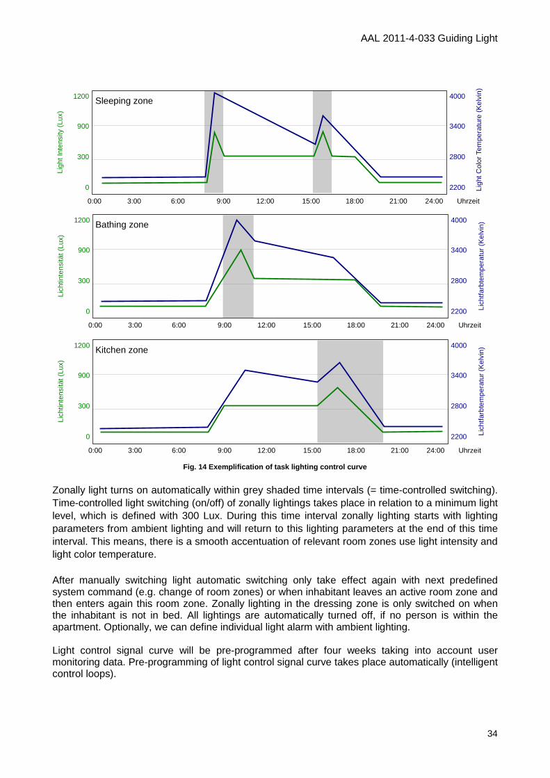
Fig. 14 Exemplification of task lighting control cu rve
Zonally light turns on automatically within grey shaded time intervals (= time-controlled switching). Time-controlled light switching (on/off) of zonally lightings takes place in relation to a minimum light level, which is defined with 300 Lux. During this time interval zonally lighting starts with lighting parameters from ambient lighting and will return to this lighting parameters at the end of this time interval. This means, there is a smooth accentuation of relevant room zones use light intensity and light color temperature. After manually switching light automatic switching only take effect again with next predefined system command (e.g. change of room zones) or when inhabitant leaves an active room zone and then enters again this room zone. Zonally lighting in the dressing zone is only switched on when the inhabitant is not in bed. All lightings are automatically turned off, if no person is within the apartment. Optionally, we can define individual light alarm with ambient lighting. Light control signal curve will be pre-programmed after four weeks taking into account user monitoring data. Pre-programming of light control signal curve takes place automatically (intelligent control loops).
1200
900
300
0
4000
3400
2800
2200
Lich
tinte
nsitä
t (Lu
x)
Lich
tfarb
tem
pera
tur
(Kel
vin)
0:00 3:00 6:00 9:00 12:00 15:00 18:00 21:00 24:00 Uhrzeit
Bathing zone
1200
900
300
0
4000
3400
2800
2200
Lich
tinte
nsitä
t (Lu
x)
Lich
tfarb
tem
pera
tur
(Kel
vin)
0:00 3:00 6:00 9:00 12:00 15:00 18:00 21:00 24:00 Uhrzeit
Kitchen zone
1200
900
300
0
4000
3400
2800
2200
Ligh
t Int
ensi
ty (
Lux)
Ligh
t Col
or T
empe
ratu
re (
Kel
vin)
0:00 3:00 6:00 9:00 12:00 15:00 18:00 21:00 24:00 Uhrzeit
Sleeping zone
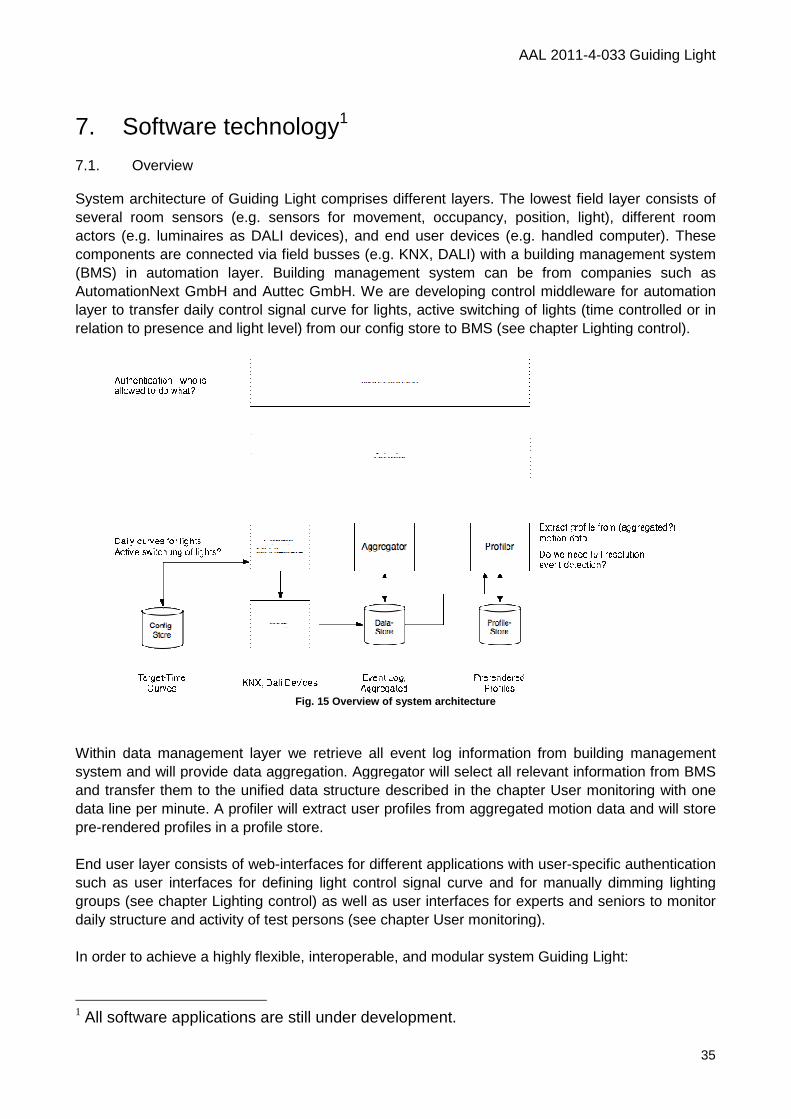
7. Software technology 7.1. Overview System architecture of Guiding Light comprises different layers. The lowest field layer consists several room sensors (e.g. sensors for movement, occupancy, position, light), different room actors (e.g. luminaires as DALI devices), and end user devices (e.g. components are connected via field busses (e.g. KNX, DALI) with a building m(BMS) in automation layer. Building management system can be from companies such as AutomationNext GmbH and Auttec GmbH. We are developing control middleware for automation layer to transfer daily control signal curve for lights, active swrelation to presence and light level) from our config store to BMS (see chapter Lighting control).
Within data management layer we retrieve all system and will provide data aggregation. Aggregator will select all relevant information from BMS and transfer them to the unified data structure described in the chapter User monitoring with one data line per minute. A profiler will extract user profiles from aggregated motion data and will store pre-rendered profiles in a profile store. End user layer consists of web-interfaces for different applications with usersuch as user interfaces for defining light control signal curve and for manually dimming lighting groups (see chapter Lighting control) as well as user interfaces for experts and seniors to monitor daily structure and activity of test persons (see chapter User monitoring). In order to achieve a highly flexible, interoperable, and modular system Guiding Light:
1 All software applications are still under
AAL 2011
Software technology1
System architecture of Guiding Light comprises different layers. The lowest field layer consists room sensors (e.g. sensors for movement, occupancy, position, light), different room
actors (e.g. luminaires as DALI devices), and end user devices (e.g. handledcomponents are connected via field busses (e.g. KNX, DALI) with a building m(BMS) in automation layer. Building management system can be from companies such as AutomationNext GmbH and Auttec GmbH. We are developing control middleware for automation layer to transfer daily control signal curve for lights, active switching of lights (time controlled or in relation to presence and light level) from our config store to BMS (see chapter Lighting control).
Fig. 15 Overview of system architecture
Within data management layer we retrieve all event log information from building management system and will provide data aggregation. Aggregator will select all relevant information from BMS and transfer them to the unified data structure described in the chapter User monitoring with one
r minute. A profiler will extract user profiles from aggregated motion data and will store rendered profiles in a profile store.
interfaces for different applications with user-specific authentication aces for defining light control signal curve and for manually dimming lighting
groups (see chapter Lighting control) as well as user interfaces for experts and seniors to monitor daily structure and activity of test persons (see chapter User monitoring).
In order to achieve a highly flexible, interoperable, and modular system Guiding Light:
All software applications are still under development.
AAL 2011-4-033 Guiding Light
35
System architecture of Guiding Light comprises different layers. The lowest field layer consists of room sensors (e.g. sensors for movement, occupancy, position, light), different room
handled computer). These components are connected via field busses (e.g. KNX, DALI) with a building management system (BMS) in automation layer. Building management system can be from companies such as AutomationNext GmbH and Auttec GmbH. We are developing control middleware for automation
itching of lights (time controlled or in relation to presence and light level) from our config store to BMS (see chapter Lighting control).
event log information from building management system and will provide data aggregation. Aggregator will select all relevant information from BMS and transfer them to the unified data structure described in the chapter User monitoring with one
r minute. A profiler will extract user profiles from aggregated motion data and will store
specific authentication aces for defining light control signal curve and for manually dimming lighting
groups (see chapter Lighting control) as well as user interfaces for experts and seniors to monitor
In order to achieve a highly flexible, interoperable, and modular system Guiding Light:
AAL 2011-4-033 Guiding Light
36
• combines peer-to-peer network with server-based network to form a strong efficient portable and compatible network architecture,
• implements a multilayered, modular software architecture to ensure effective configuring, scaling, and servicing,
• takes care of hardware heterogeneity and allow different communication technologies like Ethernet, ZigBee, Bluetooth, WLAN,
• considers current bus systems like EIB/KNX, LM, DALI, EnOcean, Beckhoff ADS and EtherCAT, and
• utilizes an open and documented XML-interface to give third-party developers the opportunity to create own applications (plug-ins) for our system.
7.2. System configuration Each Guiding Light system consists of several actor and sensor components. An apartment has several lighting groups used as actors (see annex). In our test cases there are approximately six lighting groups per apartment (e.g. for kitchen zone, living zone, bath zone, sleeping zone, and dressing zone). An apartment has several manual light switches and several different sensors, such as light sensors, motion sensors, and an entrance sensor. Depending on technical solution door contact switches or light-sensitive barriers are used as entrance sensor. One lighting group might address several manual switches, light sensors, and motion sensors. Manual switches might have a dim function which can be turned on or off. The overall system is configured in such a way that, if user manually turns light on or off, this status remains until next system command.
System parameter Content Remarks
Lighting groups address an apartment has several lighting groups; one lighting group might cover several luminaires
Light sensors assignment one lighting group might address several light sensors
Motion sensors assignment one lighting group might address several motion sensors; a motion sensor might scan different sectors
Room zones assignment assignment of sectors of motion sensors to room zones; room zones are predefined according to typical use of apartment
Manual switches assignment one lighting group might address several manual switches
Manual dimming on/off dim function of each manual switch can be turned on or off
Entrance sensor address depending on technical solution door contact switches or light-sensitive barriers are used as entrance sensor
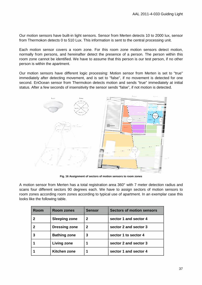
Our motion sensors have built-in light sensors. Sensor from Thermokon detects 0 to 510 Lux. This information is sent to the central processing unit. Each motion sensor covers a room zone. For this room zone motion sensors detect motion, normally from persons, and hereinafter detect the presence of a person. The person withroom zone cannot be identified. We have to assume that this person is our test person, if no other person is within the apartment. Our motion sensors have different logic processing: Motion sensor from Merten is set to "true" immediately after detecting movement, and is set to "false", if no movement is detected for one second. EnOcean sensor from Thermokon detects motion and sends “true” immediately at initial status. After a few seconds of insensitivity the sensor sends “false”, if not motion is
Fig. 16 Assignment of sectors of motion sensors to room zon es
A motion sensor from Merten has a total registration area 360° with 7 meter detection radius and scans four different sectors 90 degrees each. We have to assign sectors of motion sensors to room zones according room zones according to typical use of apartment. In an exemplar case thlooks like the following table.
Room Room zones
2 Sleeping zone
2 Dressing zone
3 Bathing zone
1 Living zone
1 Kitchen zone
AAL 2011
in light sensors. Sensor from Merten detects 10 to 2000 ldetects 0 to 510 Lux. This information is sent to the central processing unit.
Each motion sensor covers a room zone. For this room zone motion sensors detect motion, normally from persons, and hereinafter detect the presence of a person. The person withroom zone cannot be identified. We have to assume that this person is our test person, if no other
Our motion sensors have different logic processing: Motion sensor from Merten is set to "true" tecting movement, and is set to "false", if no movement is detected for one
second. EnOcean sensor from Thermokon detects motion and sends “true” immediately at initial status. After a few seconds of insensitivity the sensor sends “false”, if not motion is
Assignment of sectors of motion sensors to room zon es
has a total registration area 360° with 7 meter detection radius and scans four different sectors 90 degrees each. We have to assign sectors of motion sensors to room zones according room zones according to typical use of apartment. In an exemplar case th
Room zones Sensor Sectors of motion sensors
Sleeping zone 2 sector 1 and sector 4
Dressing zone 2 sector 2 and sector 3
Bathing zone 3 sector 1 to sector 4
Living zone 1 sector 2 and sector 3
Kitchen zone 1 sector 1 and sector 4
AAL 2011-4-033 Guiding Light
37
from Merten detects 10 to 2000 lux, sensor detects 0 to 510 Lux. This information is sent to the central processing unit.
Each motion sensor covers a room zone. For this room zone motion sensors detect motion, normally from persons, and hereinafter detect the presence of a person. The person within this room zone cannot be identified. We have to assume that this person is our test person, if no other
Our motion sensors have different logic processing: Motion sensor from Merten is set to "true" tecting movement, and is set to "false", if no movement is detected for one
second. EnOcean sensor from Thermokon detects motion and sends “true” immediately at initial status. After a few seconds of insensitivity the sensor sends “false”, if not motion is detected.
has a total registration area 360° with 7 meter detection radius and scans four different sectors 90 degrees each. We have to assign sectors of motion sensors to room zones according room zones according to typical use of apartment. In an exemplar case this
Sectors of motion sensors
sector 1 and sector 4
sector 2 and sector 3
3
sector 1 and sector 4
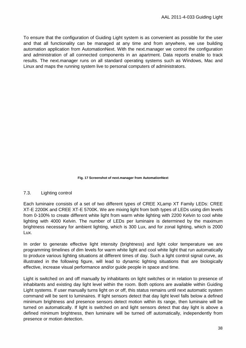
To ensure that the configuration of Guiding Light system is as convenient as possible for the user and that all functionality can be managed at any time and from anywhere, we use building automation application from AutomationNext. With the next.manager we control the configuration and administration of all connected components in an apartment. Data reports enable to track results. The next.manager runs on all standard operating systems such as Windows, Mac and Linux and maps the running system live to personal computers of administrators.
Fig. 17
7.3. Lighting control Each luminaire consists of a set of two different types of CREE XLampXT-E 2200K and CREE XT-E 5700K. We are mixing light from both types of LEDs using dim levels from 0-100% to create different white light from warm white lighting with 2200 Kelvin to cool white lighting with 4000 Kelvin. The number of brightness necessary for ambient lighting, which is 300 Lux, and for zonal lighting, which is 2000 Lux. In order to generate effective light intensity (brightness) and light color temperature we are programming timelines of dim levels for warm white light and cool white light that run automatically to produce various lighting situations at different times of day. Such a light control signal curve, as illustrated in the following figure, will lead to dynamic effective, increase visual performance and/or guide people in space and time. Light is switched on and off manually by inhabitants on light switches or in relation to presence of inhabitants and existing day lightLight systems. If user manually turns light on or off, this status remains until next automatic system command will be sent to luminaires. If light sensors detect that day light level falls minimum brightness and presence sensors detect motion within its range, then luminaire will be turned on automatically. If light is switched on and light sensors detect that day light is above a defined minimum brightness, then luminaire wipresence or motion detection.
AAL 2011
To ensure that the configuration of Guiding Light system is as convenient as possible for the user and that all functionality can be managed at any time and from anywhere, we use building
from AutomationNext. With the next.manager we control the configuration and administration of all connected components in an apartment. Data reports enable to track results. The next.manager runs on all standard operating systems such as Windows, Mac and inux and maps the running system live to personal computers of administrators.
Screenshot of next.manager from AutomationNext
Each luminaire consists of a set of two different types of CREE XLamp XT Family LEDs: CREE E 5700K. We are mixing light from both types of LEDs using dim levels
100% to create different white light from warm white lighting with 2200 Kelvin to cool white lighting with 4000 Kelvin. The number of LEDs per luminaire is determined by the maximum brightness necessary for ambient lighting, which is 300 Lux, and for zonal lighting, which is 2000
In order to generate effective light intensity (brightness) and light color temperature we are ming timelines of dim levels for warm white light and cool white light that run automatically
to produce various lighting situations at different times of day. Such a light control signal curve, as illustrated in the following figure, will lead to dynamic lighting situations that are biologically effective, increase visual performance and/or guide people in space and time.
Light is switched on and off manually by inhabitants on light switches or in relation to presence of inhabitants and existing day light level within the room. Both options are available within Guiding Light systems. If user manually turns light on or off, this status remains until next automatic system command will be sent to luminaires. If light sensors detect that day light level falls minimum brightness and presence sensors detect motion within its range, then luminaire will be turned on automatically. If light is switched on and light sensors detect that day light is above a defined minimum brightness, then luminaire will be turned off automatically, independently from
AAL 2011-4-033 Guiding Light
38
To ensure that the configuration of Guiding Light system is as convenient as possible for the user and that all functionality can be managed at any time and from anywhere, we use building
from AutomationNext. With the next.manager we control the configuration and administration of all connected components in an apartment. Data reports enable to track results. The next.manager runs on all standard operating systems such as Windows, Mac and inux and maps the running system live to personal computers of administrators.
XT Family LEDs: CREE E 5700K. We are mixing light from both types of LEDs using dim levels
100% to create different white light from warm white lighting with 2200 Kelvin to cool white LEDs per luminaire is determined by the maximum
brightness necessary for ambient lighting, which is 300 Lux, and for zonal lighting, which is 2000
In order to generate effective light intensity (brightness) and light color temperature we are ming timelines of dim levels for warm white light and cool white light that run automatically
to produce various lighting situations at different times of day. Such a light control signal curve, as lighting situations that are biologically
effective, increase visual performance and/or guide people in space and time.
Light is switched on and off manually by inhabitants on light switches or in relation to presence of level within the room. Both options are available within Guiding
Light systems. If user manually turns light on or off, this status remains until next automatic system command will be sent to luminaires. If light sensors detect that day light level falls below a defined minimum brightness and presence sensors detect motion within its range, then luminaire will be turned on automatically. If light is switched on and light sensors detect that day light is above a
ll be turned off automatically, independently from
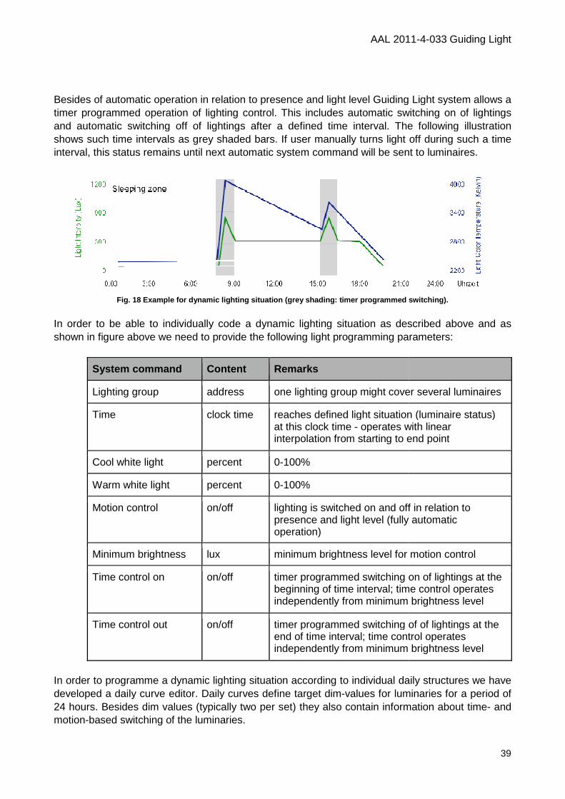
Besides of automatic operation in relation to presence and light level Guiding Light system allows a timer programmed operation of lighting control. This includes automatic sand automatic switching off of lightings after a defined time interval. The following illustration shows such time intervals as grey shaded bars. If user manually turns light off during such a time interval, this status remains until next automatic system command will be sent to luminaires.
Fig. 18 Example for dynamic lighting situation (grey shadin g: timer programmed switching).
In order to be able to individually shown in figure above we need to provide the following light programming parameters:
System command
Lighting group
Time
Cool white light
Warm white light
Motion control
Minimum brightness
Time control on
Time control out
In order to programme a dynamic lighting situation according to individual dailydeveloped a daily curve editor. Daily curves 24 hours. Besides dim values (typically two per set) they also contain information about timemotion-based switching of the luminaries.
AAL 2011
Besides of automatic operation in relation to presence and light level Guiding Light system allows a timer programmed operation of lighting control. This includes automatic switching on of lightings and automatic switching off of lightings after a defined time interval. The following illustration shows such time intervals as grey shaded bars. If user manually turns light off during such a time
il next automatic system command will be sent to luminaires.
Example for dynamic lighting situation (grey shadin g: timer programmed switching).
In order to be able to individually code a dynamic lighting situation as described above and as shown in figure above we need to provide the following light programming parameters:
Content Remarks
address one lighting group might cover several luminaires
clock time reaches defined light situation (luminaire status) at this clock time - operates with linear interpolation from starting to end point
percent 0-100%
percent 0-100%
on/off lighting is switched on and off in relation to presence and light level (fully automatic operation)
lux minimum brightness level for motion control
on/off timer programmed switching on of lightings at the beginning of time interval; time control operates independently from minimum brightness level
on/off timer programmed switching of ofend of time interval; time control operates independently from minimum brightness level
In order to programme a dynamic lighting situation according to individual dailydaily curve editor. Daily curves define target dim-values for luminaries for a period of
24 hours. Besides dim values (typically two per set) they also contain information about timebased switching of the luminaries.
AAL 2011-4-033 Guiding Light
39
Besides of automatic operation in relation to presence and light level Guiding Light system allows a witching on of lightings
and automatic switching off of lightings after a defined time interval. The following illustration shows such time intervals as grey shaded bars. If user manually turns light off during such a time
il next automatic system command will be sent to luminaires.
Example for dynamic lighting situation (grey shadin g: timer programmed switching).
a dynamic lighting situation as described above and as shown in figure above we need to provide the following light programming parameters:
one lighting group might cover several luminaires
reaches defined light situation (luminaire status) operates with linear
interpolation from starting to end point
on and off in relation to presence and light level (fully automatic
minimum brightness level for motion control
timer programmed switching on of lightings at the beginning of time interval; time control operates independently from minimum brightness level
timer programmed switching of of lightings at the end of time interval; time control operates independently from minimum brightness level
In order to programme a dynamic lighting situation according to individual daily structures we have values for luminaries for a period of
24 hours. Besides dim values (typically two per set) they also contain information about time- and
AAL 2011-4-033 Guiding Light
40
There are currently two sides accessing the guiding light daily curve backend system. On the building management system side, each Daily Curve Unit requests their current daily curve from the guiding light backend-system. These requests are typically performed at a fixed time in the day (e.g. 00:00:00) over a secure https connection. On the user-side these daily curves are defined using a web-based app inside a web-browser also using secure https connections. Light curves can be adjusted, and time based switch commands can be defined. Also motion based switching can be activated in accordance to a definable brightness threshold. Also an effective date can be set to be able to schedule a curve change in future. In future a third side might be added in the form of an automated curve generator which could use the same Web API as the web-app for manual configuration.
Fig. 19 Overview about data flow in daily curve edi tor
The Daily Curve Editor is a web-app executed in an HTML5 compliant Web-browser for adjusting daily curves of the Guiding Light system. The reason for implementing the editor in form of a web-application was the platform independent nature of web-apps. Therefore the Daily Curve Editor can be run on Mac, Windows, iOS, Android or any other platform providing an HTML5 compliant browser. On the technical side, the editor is built using open source based frameworks like jQuery and jqPlot (for plotting and drag & drop editing of the curves) in combination with HTML5, CSS3 and JavaScript. Communication to the system is done over secure https requests using the JSON data format. The advantages of JSON in contrast to XML based data exchange structures are the better efficiency (less overhead as no tags are used) and easier processing on the client side. Both of these advantages are especially beneficial in the mobile space.
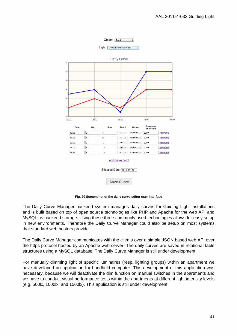
AAL 2011-4-033 Guiding Light
41
Fig. 20 Screenshot of the daily curve editor user i nterface
The Daily Curve Manager backend system manages daily curves for Guiding Light installations and is built based on top of open source technologies like PHP and Apache for the web API and MySQL as backend storage. Using these three commonly used technologies allows for easy setup in new environments. Therefore the Daily Curve Manager could also be setup on most systems that standard web hosters provide. The Daily Curve Manager communicates with the clients over a simple JSON based web API over the https protocol hosted by an Apache web server. The daily curves are saved in relational table structures using a MySQL database. The Daily Curve Manager is still under development. For manually dimming light of specific luminaires (resp. lighting groups) within an apartment we have developed an application for handheld computer. This development of this application was necessary, because we will deactivate the dim function on manual switches in the apartments and we have to conduct visual performance tests within the apartments at different light intensity levels (e.g. 500lx, 1000lx, and 1500lx). This application is still under development.
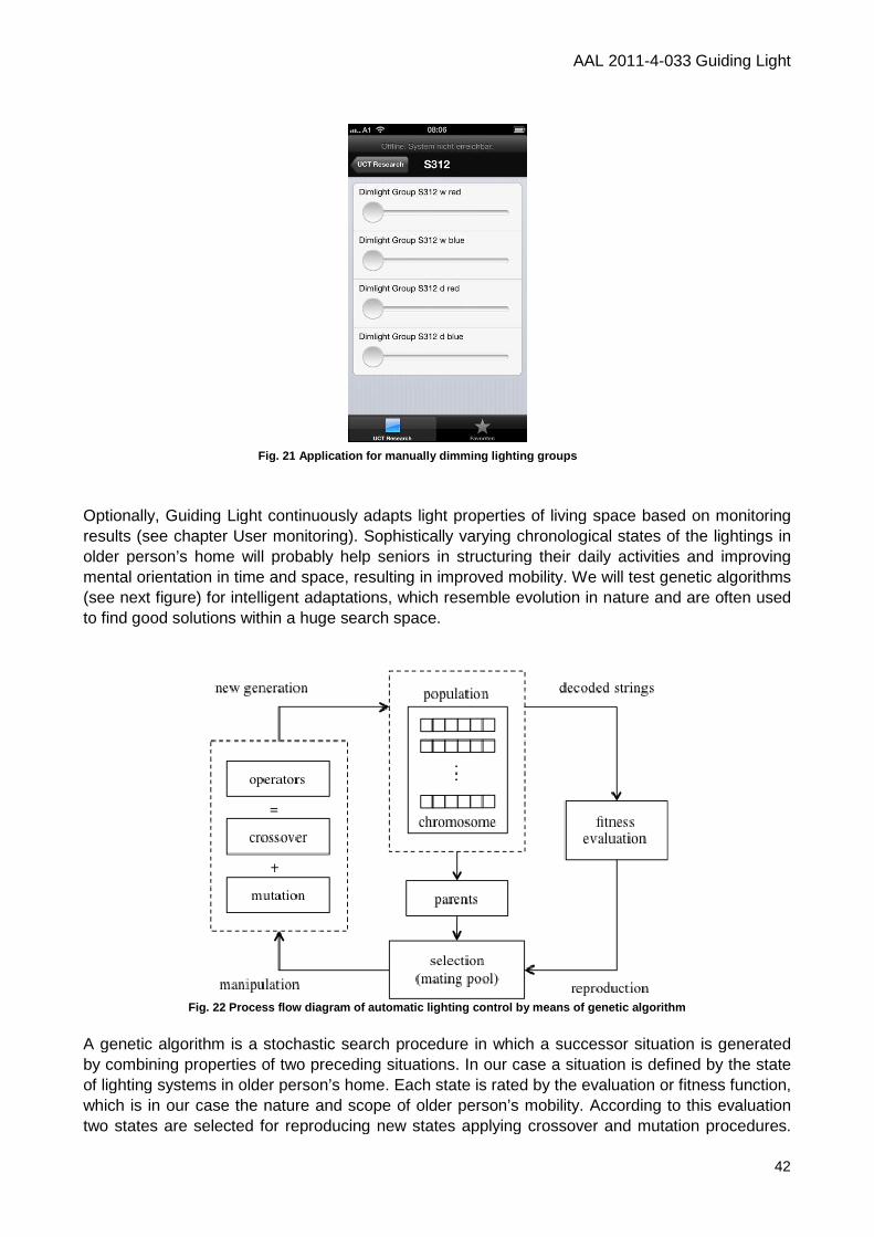
Optionally, Guiding Light continuously adapts light properties of living space based on monitoring results (see chapter User monitoring). Sophistically varying chronological states of the lightings in older person’s home will probably help seniors in strucmental orientation in time and space, resulting in improved mobility. We will test genetic algorithms (see next figure) for intelligent adaptationsto find good solutions within a huge search space.
Fig. 22 Process flow diagram of automatic lighting control by means of genetic algorithm
A genetic algorithm is a stochastic search procedure in which a successor situation is generated by combining properties of two preceding situations. In our case a situation is defined by the state of lighting systems in older person’s home. Each state is which is in our case the nature and scope of older person’s mobility. According to this evaluation two states are selected for reproducing new states applying crossover and mutation procedures.
Fig. 21 Application for manually dimming lighting groups
AAL 2011
Optionally, Guiding Light continuously adapts light properties of living space based on monitoring results (see chapter User monitoring). Sophistically varying chronological states of the lightings in older person’s home will probably help seniors in structuring their daily activities and improving mental orientation in time and space, resulting in improved mobility. We will test genetic algorithms
adaptations, which resemble evolution in nature and are often used ood solutions within a huge search space.
Process flow diagram of automatic lighting control by means of genetic algorithm
A genetic algorithm is a stochastic search procedure in which a successor situation is generated by combining properties of two preceding situations. In our case a situation is defined by the state of lighting systems in older person’s home. Each state is rated by the evaluation or fitness function, which is in our case the nature and scope of older person’s mobility. According to this evaluation two states are selected for reproducing new states applying crossover and mutation procedures.
Application for manually dimming lighting groups
AAL 2011-4-033 Guiding Light
42
Optionally, Guiding Light continuously adapts light properties of living space based on monitoring results (see chapter User monitoring). Sophistically varying chronological states of the lightings in
turing their daily activities and improving mental orientation in time and space, resulting in improved mobility. We will test genetic algorithms
, which resemble evolution in nature and are often used
Process flow diagram of automatic lighting control by means of genetic algorithm
A genetic algorithm is a stochastic search procedure in which a successor situation is generated by combining properties of two preceding situations. In our case a situation is defined by the state
rated by the evaluation or fitness function, which is in our case the nature and scope of older person’s mobility. According to this evaluation two states are selected for reproducing new states applying crossover and mutation procedures.
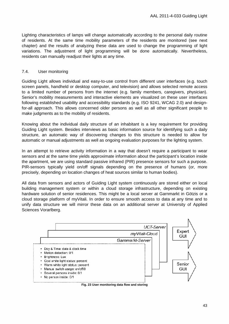
AAL 2011-4-033 Guiding Light
43
Lighting characteristics of lamps will change automatically according to the personal daily routine of residents. At the same time mobility parameters of the residents are monitored (see next chapter) and the results of analyzing these data are used to change the programming of light variations. The adjustment of light programming will be done automatically. Nevertheless, residents can manually readjust their lights at any time. 7.4. User monitoring Guiding Light allows individual and easy-to-use control from different user interfaces (e.g. touch screen panels, handheld or desktop computer, and television) and allows selected remote access to a limited number of persons from the internet (e.g. family members, caregivers, physician). Senior’s mobility measurements and interactive elements are visualized on these user interfaces following established usability and accessibility standards (e.g. ISO 9241, WCAG 2.0) and design-for-all approach. This allows concerned older persons as well as all other significant people to make judgments as to the mobility of residents. Knowing about the individual daily structure of an inhabitant is a key requirement for providing Guiding Light system. Besides interviews as basic information source for identifying such a daily structure, an automatic way of discovering changes to this structure is needed to allow for automatic or manual adjustments as well as ongoing evaluation purposes for the lighting system. In an attempt to retrieve activity information in a way that doesn’t require a participant to wear sensors and at the same time yields approximate information about the participant’s location inside the apartment, we are using standard passive infrared (PIR) presence sensors for such a purpose. PIR-sensors typically yield on/off signals depending on the presence of humans (or, more precisely, depending on location changes of heat sources similar to human bodies). All data from sensors and actors of Guiding Light system continuously are stored either on local building management system or within a cloud storage infrastructure, depending on existing hardware solution of senior residences. This might be a local server at Garnmarkt in Götzis or a cloud storage platform of myVitali. In order to ensure smooth access to data at any time and to unify data structure we will mirror these data on an additional server at University of Applied Sciences Vorarlberg.
Fig. 23 User monitoring data flow and storing
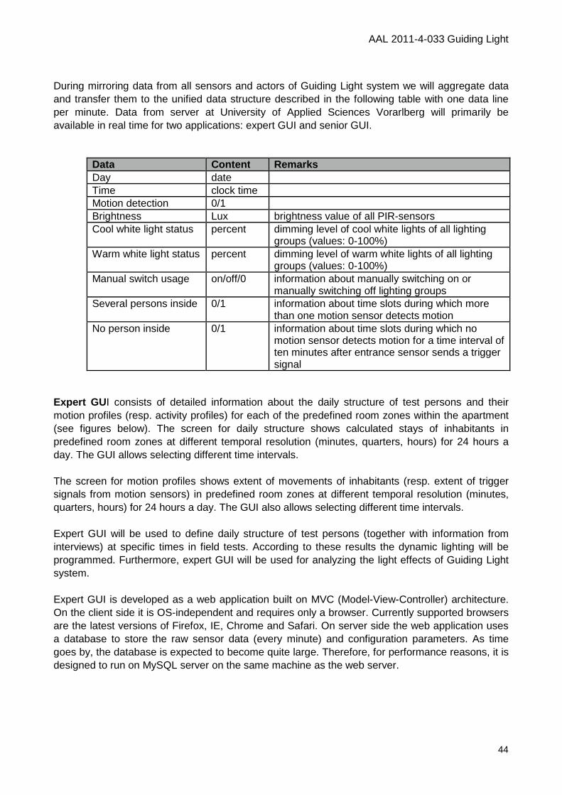
AAL 2011-4-033 Guiding Light
44
During mirroring data from all sensors and actors of Guiding Light system we will aggregate data and transfer them to the unified data structure described in the following table with one data line per minute. Data from server at University of Applied Sciences Vorarlberg will primarily be available in real time for two applications: expert GUI and senior GUI.
Data Content Remarks Day date Time clock time Motion detection 0/1 Brightness Lux brightness value of all PIR-sensors Cool white light status percent dimming level of cool white lights of all lighting
groups (values: 0-100%) Warm white light status percent dimming level of warm white lights of all lighting
groups (values: 0-100%) Manual switch usage on/off/0 information about manually switching on or
manually switching off lighting groups Several persons inside 0/1 information about time slots during which more
than one motion sensor detects motion No person inside 0/1 information about time slots during which no
motion sensor detects motion for a time interval of ten minutes after entrance sensor sends a trigger signal
Expert GU I consists of detailed information about the daily structure of test persons and their motion profiles (resp. activity profiles) for each of the predefined room zones within the apartment (see figures below). The screen for daily structure shows calculated stays of inhabitants in predefined room zones at different temporal resolution (minutes, quarters, hours) for 24 hours a day. The GUI allows selecting different time intervals. The screen for motion profiles shows extent of movements of inhabitants (resp. extent of trigger signals from motion sensors) in predefined room zones at different temporal resolution (minutes, quarters, hours) for 24 hours a day. The GUI also allows selecting different time intervals. Expert GUI will be used to define daily structure of test persons (together with information from interviews) at specific times in field tests. According to these results the dynamic lighting will be programmed. Furthermore, expert GUI will be used for analyzing the light effects of Guiding Light system. Expert GUI is developed as a web application built on MVC (Model-View-Controller) architecture. On the client side it is OS-independent and requires only a browser. Currently supported browsers are the latest versions of Firefox, IE, Chrome and Safari. On server side the web application uses a database to store the raw sensor data (every minute) and configuration parameters. As time goes by, the database is expected to become quite large. Therefore, for performance reasons, it is designed to run on MySQL server on the same machine as the web server.
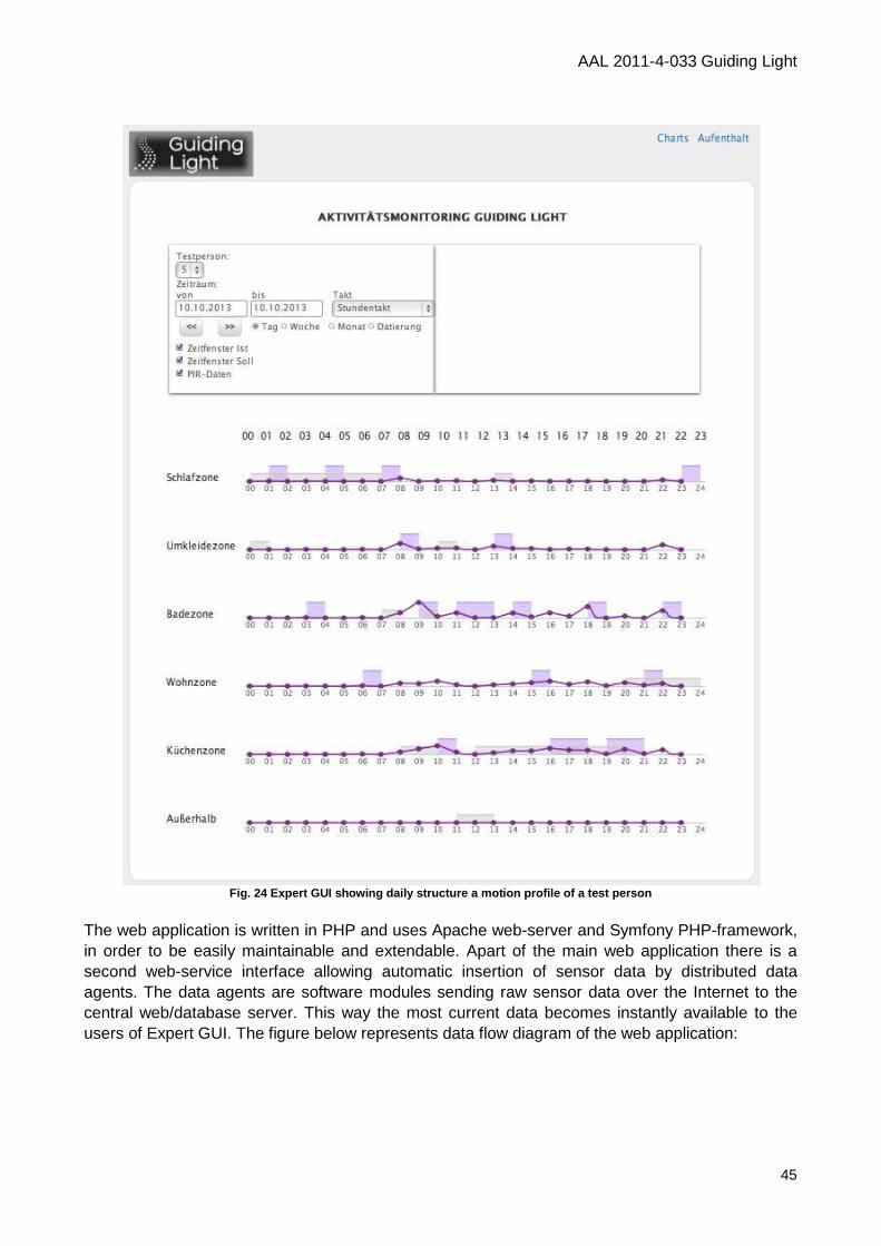
AAL 2011-4-033 Guiding Light
45
Fig. 24 Expert GUI showing daily structure a motion profile of a test person
The web application is written in PHP and uses Apache web-server and Symfony PHP-framework, in order to be easily maintainable and extendable. Apart of the main web application there is a second web-service interface allowing automatic insertion of sensor data by distributed data agents. The data agents are software modules sending raw sensor data over the Internet to the central web/database server. This way the most current data becomes instantly available to the users of Expert GUI. The figure below represents data flow diagram of the web application:
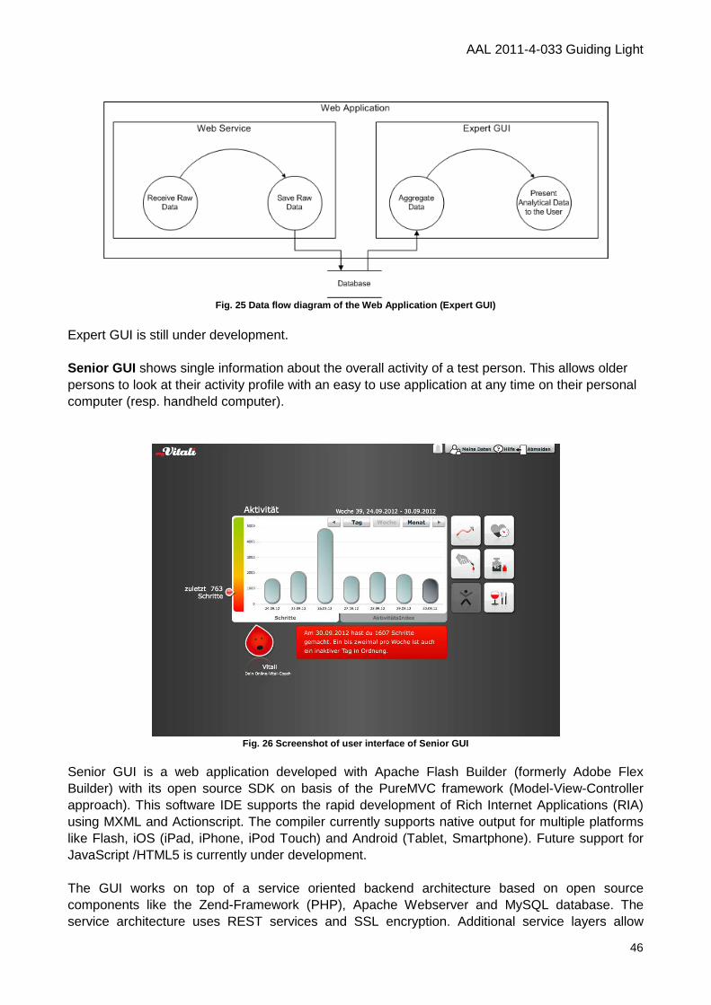
AAL 2011-4-033 Guiding Light
46
Fig. 25 Data flow diagram of the Web Application (E xpert GUI)
Expert GUI is still under development. Senior GUI shows single information about the overall activity of a test person. This allows older persons to look at their activity profile with an easy to use application at any time on their personal computer (resp. handheld computer).
Fig. 26 Screenshot of user interface of Senior GUI
Senior GUI is a web application developed with Apache Flash Builder (formerly Adobe Flex Builder) with its open source SDK on basis of the PureMVC framework (Model-View-Controller approach). This software IDE supports the rapid development of Rich Internet Applications (RIA) using MXML and Actionscript. The compiler currently supports native output for multiple platforms like Flash, iOS (iPad, iPhone, iPod Touch) and Android (Tablet, Smartphone). Future support for JavaScript /HTML5 is currently under development. The GUI works on top of a service oriented backend architecture based on open source components like the Zend-Framework (PHP), Apache Webserver and MySQL database. The service architecture uses REST services and SSL encryption. Additional service layers allow

AAL 2011-4-033 Guiding Light
47
access to third party services (XML-RPC, Java RMI, oAuth) and easy expendability. The modular architecture of the client for senior GUI provides easy possibilities for iterative development of additional functions and modules. 7.5. Bus system Guiding Light system is conceptualized as an intelligent home automation system, on the one hand designed to monitor older person’s behavior and on the other hand to adaptively control all kind of lighting sources in their home, which guide them to more indoor and outdoor mobility. Electronic devices are commercial room sensors (e.g. sensors for movement, occupancy, position, light) and different room actors (e.g. lighting devices). Optionally, resident monitoring is also taking into account vital data from health devices via ZigBee connection that is commonly applied by elderly (e.g. pulse, blood pressure and blood sugar, body weight with percentage of body fat and body water). Electronic devices at field layer are connected with central processing unit at automation layer via field bus using different communication protocols such as KNX EIB, DALI, and EnOcean. KNX EIB uses shielded twisted pair cables, through which the signal as well as 30V DC link power is transferred. For data transmission, a balanced baseband signal coding is used with a baud rate of 9600 bits per second. The Digital Addressable Lighting Interface (DALI) is an interface definition in building automation for the transmission of control signals for lighting devices. DALI ballasts are wired in parallel and linked with one another via the controller. The EnOcean technology is an energy harvesting wireless technology that combines micro energy converters with ultra low power electronics and enable wireless communications between battery-less wireless sensors, switches, controllers and gateways. Central processing unit of building management system may vary depending on management system software used in a building. In case of building management system from Auttec GmbH the controller will be a Beckhoff device. At Garnmarkt in Götzis we use such a system but this can be replaced by any industrial computer. In order to ensure fail-safe operation we are not re-programming existing building management system but use our own building management system which is connected through a consistent ADS (Automation Device Specification) interface over TCP/IP connections. We decided to perform software development for building management system from automationNext GmbH (see chapter Bus system plug-ins).
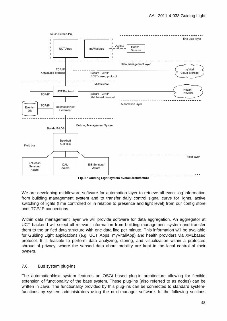
AAL 2011-4-033 Guiding Light
48
Fig. 27 Guiding Light system overall architecture
We are developing middleware software for automation layer to retrieve all event log information from building management system and to transfer daily control signal curve for lights, active switching of lights (time controlled or in relation to presence and light level) from our config store over TCP/IP connections. Within data management layer we will provide software for data aggregation. An aggregator at UCT backend will select all relevant information from building management system and transfer them to the unified data structure with one data line per minute. This information will be available for Guiding Light applications (e.g. UCT Apps, myVitaliApp) and health providers via XMLbased protocol. It is feasible to perform data analyzing, storing, and visualization within a protected shroud of privacy, where the sensed data about mobility are kept in the local control of their owners. 7.6. Bus system plug-ins The automationNext system features an OSGi based plug-in architecture allowing for flexible extension of functionality of the base system. These plug-ins (also referred to as nodes) can be written in Java. The functionality provided by this plug-ins can be connected to standard system-functions by system administrators using the next-manager software. In the following sections
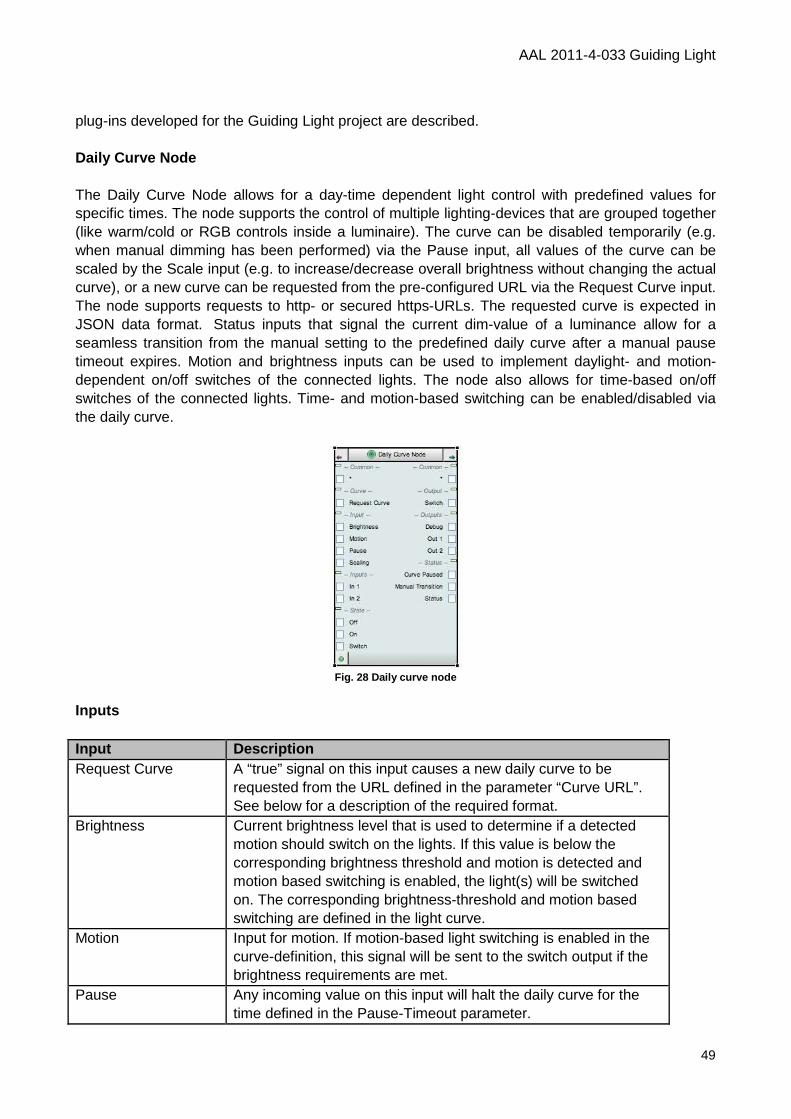
AAL 2011-4-033 Guiding Light
49
plug-ins developed for the Guiding Light project are described. Daily Curve Node The Daily Curve Node allows for a day-time dependent light control with predefined values for specific times. The node supports the control of multiple lighting-devices that are grouped together (like warm/cold or RGB controls inside a luminaire). The curve can be disabled temporarily (e.g. when manual dimming has been performed) via the Pause input, all values of the curve can be scaled by the Scale input (e.g. to increase/decrease overall brightness without changing the actual curve), or a new curve can be requested from the pre-configured URL via the Request Curve input. The node supports requests to http- or secured https-URLs. The requested curve is expected in JSON data format.�Status inputs that signal the current dim-value of a luminance allow for a seamless transition from the manual setting to the predefined daily curve after a manual pause timeout expires. Motion and brightness inputs can be used to implement daylight- and motion-dependent on/off switches of the connected lights. The node also allows for time-based on/off switches of the connected lights. Time- and motion-based switching can be enabled/disabled via the daily curve.
Fig. 28 Daily curve node
Inputs Input Description Request Curve A “true” signal on this input causes a new daily curve to be
requested from the URL defined in the parameter “Curve URL”. See below for a description of the required format.
Brightness Current brightness level that is used to determine if a detected motion should switch on the lights. If this value is below the corresponding brightness threshold and motion is detected and motion based switching is enabled, the light(s) will be switched on. The corresponding brightness-threshold and motion based switching are defined in the light curve.
Motion Input for motion. If motion-based light switching is enabled in the curve-definition, this signal will be sent to the switch output if the brightness requirements are met.
Pause Any incoming value on this input will halt the daily curve for the time defined in the Pause-Timeout parameter.
AAL 2011-4-033 Guiding Light
50
Scaling Any curve value defined in the daily curve will be scaled by this factor before it’s sent to the output. This allows for scaling an entire curve without the need to change all individual values explicitly. One particular usage example could be a daylight dependent scaling of the output values.
In* These inputs report the current control-value of the connected lights and allow for a seamless transition between manual and automatic states. These inputs should therefore be connected to the status outputs of the light control nodes.
On/Off/Switch These inputs allow for enabling/disabling the entire node function (e.g. switching daily curve control on/off).
Outputs Output Description Switch Switches the output on/off based on either time and/or motion
events. Debug For debugging purposes only - it indicates the internal state of the
node. This output will be removed in the final version. Out* Target output value (should be connected to the corresponding
dim-input of the light nodes). Curve Paused Signals if the daily curve is currently paused. Manual Transition Signals an ongoing transition between manual and automatic
mode. Status Signals the state of the node (if the daily curve control node is on
or off).
Parameter Parameter Description Curve-Config The curve definition (see below for a detailed description of the
format). Typically this setting is requested from a URL. Curve Count Defines how many target value outputs will be controlled. By
using this parameter, parts of the outputs defined in a curve could be ignored (only the first n will be used). This value must not be greater than the number of target values defined in the daily curve definition.
Curve URL The URL from where a curve should be requested. Supported URLs start with http or https for secured connections. If this field is empty, no action will be performed after a “Request Curve” input.
Time-Shift The daily curve will be shifted by this value along the time-axis (value in seconds). This allows for easy time-shifting of an entire curve (e.g. shift the entire curve by 15 minutes).
Min-Change Defines a minimum change of the calculated output before the new value is actually sent to the output. This setting helps to reduce traffic on the system.
AAL 2011-4-033 Guiding Light
51
Pause Timeout Defines the time (in seconds) that the curve will be paused after a Pause input is received.
Ticker Interval Defines the update cycle time (in seconds). E.g. an entry of 1 will cause the outputs to be calculated every second. Small values might lead to high system load (depending on the count of total daily curve nodes), big values might cause recognizable brightness changes after each cycle.
Transition Time Defines the transition time (in seconds) between the manual light level and the daily curve level, after a manual pause timeout.
Curve Definition Format The daily curve is defined in the following format: <Time in HH:MM:SS form> <SwitchMode> <MotionActive> <BrightnessThreshold> <TargetValue 1> ...<TargetValue n> SwitchMode: �0...no action, 1...switch lights on, 2...switch lights off MotionActive: 0...no action on motion, 1...switch on/off on motion input if it’s too dark in the room (defined by brightness threshold). BrightnessThreshold: � The value (typically in lux) that defines the upper bound of available brightness for which a motion event should trigger a light on/off switch TargetValue*:� The desired output control value for this time in percent (0-100) for this light channel. Columns are separated by a space character; individual entries can be separated either by a newline character or a semicolon. The following example shows a simple curve-definition for two outputs in plain text format, where time- and motion based switching are disabled. During the night the illumination level is kept at a 20% level. Between 6 and 12 the lights will be increased from a 20% to a 100% level. Between 12 and 18 the first output will be dimmed from a 100% to an 80% level, and the second output from a 100% to a 40% level. Until 22 both outputs are dimmed to the 20% level again. Levels in between two defined times will be linearly interpolated. Note that the curve-values automatically wrap around in time.�� 06:00:00 0 0 1000 20 20 12:00:00 0 0 1000 100 100� 18:00:00 0 0 1000 80 40 22:00:00 0 0 1000 20 20 The following example shows the same curve in JSON data format: [
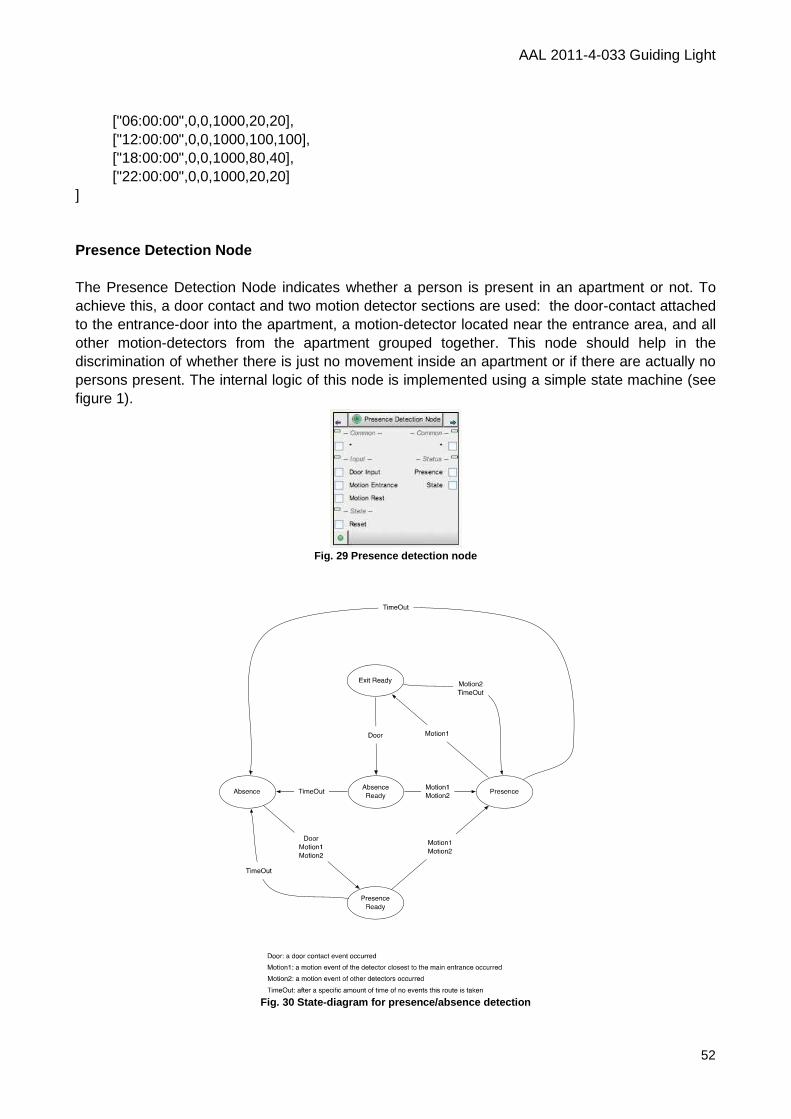
AAL 2011-4-033 Guiding Light
52
["06:00:00",0,0,1000,20,20], ["12:00:00",0,0,1000,100,100], ["18:00:00",0,0,1000,80,40], ["22:00:00",0,0,1000,20,20] ] Presence Detection Node The Presence Detection Node indicates whether a person is present in an apartment or not. To achieve this, a door contact and two motion detector sections are used: the door-contact attached to the entrance-door into the apartment, a motion-detector located near the entrance area, and all other motion-detectors from the apartment grouped together. This node should help in the discrimination of whether there is just no movement inside an apartment or if there are actually no persons present. The internal logic of this node is implemented using a simple state machine (see figure 1).
Fig. 29 Presence detection node
Fig. 30 State-diagram for presence/absence detectio n
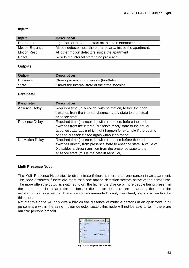
AAL 2011-4-033 Guiding Light
53
Inputs Input Description Door Input Light barrier or door-contact on the main entrance door. Motion Entrance Motion detector near the entrance area inside the apartment. Motion Rest All other motion detectors inside the apartment Reset Resets the internal state to no presence.
Outputs Output Description Presence Shows presence or absence (true/false) State Shows the internal state of the state machine. Parameter Parameter Description Absence Delay Required time (in seconds) with no motion, before the node
switches from the internal absence ready state to the actual absence state.
Presence Delay Required time (in seconds) with no motion, before the node switches from the internal presence ready state to the actual absence state again (this might happen for example if the door is opened but then closed again without entrance).
No Motion Delay Required time (in seconds) with no motion before the node switches directly from presence state to absence state. A value of 0 disables a direct transition from the presence state to the absence state (this is the default behavior).
Multi Presence Node The Multi Presence Node tries to discriminate if there is more than one person in an apartment. The node observes if there are more than one motion detection sectors active at the same time. The more often the output is switched to on, the higher the chance of more people being present in the apartment. The clearer the sections of the motion detectors are separated, the better the results for this node will be. Therefore it’s recommended to only use clearly separated sectors for this node. Not that this node will only give a hint on the presence of multiple persons in an apartment. If all persons are within the same motion detector sector, this node will not be able to tell if there are multiple persons present.
Fig. 31 Multi-presence node
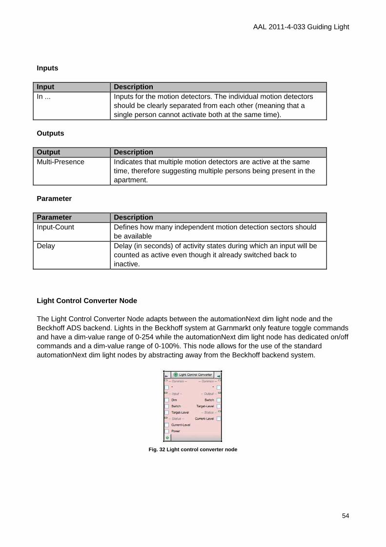
AAL 2011-4-033 Guiding Light
54
Inputs Input Description In ... Inputs for the motion detectors. The individual motion detectors
should be clearly separated from each other (meaning that a single person cannot activate both at the same time).
Outputs Output Description Multi-Presence Indicates that multiple motion detectors are active at the same
time, therefore suggesting multiple persons being present in the apartment.
Parameter Parameter Description Input-Count Defines how many independent motion detection sectors should
be available Delay Delay (in seconds) of activity states during which an input will be
counted as active even though it already switched back to inactive.
Light Control Converter Node The Light Control Converter Node adapts between the automationNext dim light node and the Beckhoff ADS backend. Lights in the Beckhoff system at Garnmarkt only feature toggle commands and have a dim-value range of 0-254 while the automationNext dim light node has dedicated on/off commands and a dim-value range of 0-100%. This node allows for the use of the standard automationNext dim light nodes by abstracting away from the Beckhoff backend system.
Fig. 32 Light control converter node
AAL 2011-4-033 Guiding Light
55
Inputs Input Description Dim The Dim-input for standard Dim-outputs of automationNext dim
light nodes (values 0...100%). Switch Switch-input for standard Switch-outputs of automationNext dim
light nodes (values on/off). Target-Level Setting a target level for the output without switching the device
on/off (values 0...100%). In Guiding Light this will mostly be connected to a daily curve output.
Current-Level The current level of a light from the target device (values 0...254). In Guiding Light this will be the actual dim value of the Beckhoff light device.
Power The power state of the target device (values on/off). In Guiding Light this will be the actual on/off state of the Beckhoff light device.
Outputs Output Description Switch This output can be connected to the toggle input of the Beckhoff
light device. Target Level This output can be connected to the target value of the Beckhoff
light device (values 0...254) Current Level Shows the current dim level of the Beckhoff device in the value
range of the automationNext dim light node (values 0...100%) and is usually connected to the Status input of the automationNext dim light node.
Parameter Parameter Description Scale Defines the scaling factor between the value ranges of the
automationNext dim light node and the Beckhoff light devices. By default this is set to 2.54 and usually should not be changed.
AAL 2011-4-033 Guiding Light
56
Annex References [1] D1.1 Medical, psychological, and technological framework
[2] D2.1 Applicable hardware components
[3] D2.2 Applicable software components