F-manual for Fusion Welding of Rails by the Alumino-Thermic Process-2006

Conference on Railway Excellence
Adelaide, 5 – 7 May 2014
ALUMINOTHERMIC WELDING OF RAILS: IMPROVED QUALIFICATION AND PERFORMANCE UNDER HEAVY HAUL CONDITIONS
Iman Salehi1, Bahar Khodabakhshi2, Peter Mutton3 and Anna Paradowska4
1PhD, 2MSc Candidate, 3MSc, 4PhD 1,3Institute of Railway Technology, Monash University, Clayton, VIC, Australia
2Department of Mechanical and Aerospace Engineering, Monash University, Clayton, VIC, Australia 4Australian Nuclear Science and Technology Organisation (ANSTO), Lucas Heights, NSW, Australia
SUMMARY
Aluminothermic welding continues to be used widely throughout the rail industry, due to its low capital cost and flexibility of use. A range of weld types are available from the two manufacturers who support the Australian market; these vary in terms of collar design, preheating conditions, etc. Single-use crucibles, which are now commonly used, have overcome some of the inherent disadvantages of multi-use crucibles. However the reliability of aluminothermic welds continues to be lower than that of flashbutt welds, particularly under heavy haul conditions where aluminothermic welds are responsible for the majority of rail defects and broken rails.
Failure modes in aluminothermic welds can vary depending on the characteristics of the individual weld type and the service conditions, although the majority of failures are associated with fatigue cracking at the top or underside of the rail foot. Other failure modes include fatigue cracking in either web or underhead regions; these modes are strongly dependent on the weld collar design and residual stress levels. Qualification requirements for aluminothermic welds in the current Australian standard include mandatory fatigue testing of the rail foot, and an optional web fatigue test which is generally applied when approving welding procedures for some heavy haul conditions. At present there is no established test procedure for fatigue of the underhead region.
Several concurrent activities being undertaken with the support of both consumable manufacturers and some heavy haul rail systems, in conjunction with the Australian Nuclear Science and Technology Organisation (ANSTO), aimed at improving the reliability of aluminothermic welds. These include neutron diffraction measurement of residual stress levels in the critical regions of the weld collar, development of a fatigue test methodology for the underhead region, and an enhanced welder training and audit program which provides the opportunity to address any issues with consumables or equipment in a timely manner.
1. INTRODUCTION
Aluminothermic (AT) welding is a simple and well-established rail joining procedure which is widely used for in-track welding associated with defect removal and re-rail processes. Operational advantages of ATW such as fast installation, availability and portability of equipment are sometimes offset by the cast-like nature of the process and variations in the quality of finished welds due to the operator dependability of the welding procedure. Previous studies have shown that field-welded ATWs have been frequent sources of failures in Australian heavy haul railway systems [1]. The quality issues range from exterior geometric variations and undesirable stress concentrations on the weld surface to lack of material and structural integrity in the form of casting defects, inclusions and cracks which can form fatigue or overload failures in presence of
high residual stresses resulting from the welding process [1, 2].
One of the most common aluminothermic weld failure modes currently observed in Australian heavy haul railways is a vertical fracture or straight break associated with fatigue crack initiation at the weld collar edge and subsequent crack propagation in a near vertical direction under Mode I loading, eventually leading to fracture through the entire rail section (Fig. 1a). This failure mode in the weld type currently used in Australian heavy haul system (Type A), typically initiates on top of the rail foot and underhead region of the weld, at locations of high stress concentration which may include surface or near-surface defects such as cold laps or flashings. The propagation pattern of this failure suggests that tensile longitudinal stresses in the rail section including the bending stress resulting from the service loading, residual stress arising from the welding

I. Salehi1, B Khodabakhshi2, P. Mutton1 and A. Paradowska3 Aluminothermic Welding of Rails: Improved 1Institute of Railway Technology, Monash University Qualification and Performance under Heavy 2Department of Mechanical and Aerospace Engineering, Monash University Haul Conditions 3Australian Nuclear Science and Technology Organisation (ANSTO)
Conference On Railway Excellence
Adelaide, 5 – 7 May 2014
procedure and seasonal thermal stress have important influence on the initiation and propagation of this failure mode.
Figure 1: ATW failures, a) Straight break initiated at the underhead and; b) HSW
Horizontal Split Web (HSW) is another ATW failure mode which involves the development of a horizontal fatigue crack which initiates from a surface or near-surface defects in the weld collar, generally in the mid- or upper-web region (Fig. 1b). High cyclic vertical stresses due to transverse bending, and vertical residual stresses, are among important parameters influencing nucleation and growth of HSW failures. The Type A weld shown in Fig. 1 is less sensitive to this failure type than some ATW processes used previously [1, 3]. HSW failures in the Type A weld are often associated with incorrect preheating conditions, which can be addressed through the welder auditing program.
The current paper provides a brief introduction to several activities being undertaken to address some of the issues relating to the operational performance of aluminothermic welds, particularly in heavy haul rail systems. The preliminary steps in developing the required fatigue testing system for the underhead region are described and the results of the validation tests on stress variation under the proposed loading scenario are provided. In addition the application of neutron diffraction
method in accurately measuring the residual stress in critical regions of the weld which are not accessible to typical stress measurement techniques such as strain gauging is introduced.
2. NOTATION
��(�) Shear stress amplitude
��(�) Hydrostatic stress
� Material parameter in Dang Van criterion
� Material parameter in Dang Van criterion
λ Wavelength of neutron beam
Lattice spacing
� Beam diffraction angle
3. FATIGUE ANALYSIS
A previous research project by the authors investigated the fatigue behaviour of the aluminothermic rail weld with respect to straight break formation at the collar edge, and quantified the effect of operational parameters such as curving and hunting, track support stiffness and residual stress distribution [4, 5]. The preliminary stage of the study comprised a thermo-structural finite element simulation of a specific length of railway track which included elastic foundation, seasonal thermal stresses and a moving load representative of a passing wheel to determine the stress cycle at the points of interest on the collar edge. The analysis of bending stresses on the weld section identified longitudinal tensile stress at the underhead region of the weld as the wheel passes on the weld section (Fig. 2). The underhead region experiences a tension spike which results from the local bending of the rail head supported by the web region. Measurement of longitudinal stress at the vicinity of the collar edge using the strain gauge technique has shown similar tension spikes occurring in real service conditions (Fig. 3). Previous analysis showed that the severity of tension spike at the underhead of each side of the weld (gauge or field) increases as the wheel/rail contact patch moves closer to that side [6]; this condition is regularly found in the high rail of sharp curves.
Subsequent to the stress analysis a multi-axial fatigue analysis was performed using the Dang Van high cycle fatigue criterion to determine the most critical locations of the collar edge in terms of fatigue crack initiation. According to the criterion in its simple linear form, a fatigue crack will initiate at a point of material if the inequality (1) is fulfilled on a shear plane passing through that particular point during at least one time portion in the whole stress cycle [7].
��(�) + ���(�) > � (1)
(a)
(b)

I. Salehi1, B Khodabakhshi2, P. Mutton1 and A. Paradowska3 Aluminothermic Welding of Rails: Improved 1Institute of Railway Technology, Monash University Qualification and Performance under Heavy 2Department of Mechanical and Aerospace Engineering, Monash University Haul Conditions 3Australian Nuclear Science and Technology Organisation (ANSTO)
Conference On Railway Excellence
Adelaide, 5 – 7 May 2014
Figure 2: Longitudinal stress contour on two types of ATWs for a contact load of 171.7kN
located on the centreline of the weld and rail; localised tensile stress is circled
Figure 3: Successive occurrence of tension spike at the underhead due to passage of
several wheels; data for a high rail of a 68 kg/m section in a 918 m radius curve subjected to
high axle load conditions
Here, ��(�) is the shear stress amplitude on the considered shear plane, ��(�) is the hydrostatic stress at that point of material, � is a material constant and � is the fatigue strength of material in pure torsion. The left side of the inequality is a numerical index for fatigue damage which is largely dependent on the shear stress amplitude on the critical plane and a small fraction of the hydrostatic stress.
Fig. 4 illustrates the fatigue damage calculated using equation 1 on the collar edge of two aluminothermic welds with different geometric designs in a tangent track as well as a curved track with a contact patch displaced 25mm towards the gauge side. As the figure suggests, damage is substantial at the underhead region of both welds and exacerbates for the displaced rail/wheel contact patch. The damage value can even exceed the fatigue parameter � implying that crack initiation is highly likely at this region. In fact the underhead region is the most critical
region of the weld section in a defect free condition. It is believed that the severity of fatigue damage at the underhead mainly relates to the complex state of stress at this region, which shows a successive variation of stress from highly compressive to highly tensile (Fig. 3). The large range and change of direction in the longitudinal stress can result in radical changes in the direction and value of the shear stress vector and this enlarges the resulting shear stress amplitude on the critical plane. The typical high tensile longitudinal residual stress at the underhead region of the weld (around 200 to 300 MPa), also facilitates crack initiation through its effect on the hydrostatic stress.
Figure 4: Fatigue damage at the collar edge of two types of welds, a) in tangent track; and b)
eccentric contact patch located 25mm from the centreline of the weld
The residual stress is not only influential in formation of fatigue cracks but also affects the propagation of existing cracks. A previous study by the authors suggested that high longitudinal residual stress reduces the threshold stress intensity factor range of the material (∆Kth) and hence enhances fatigue crack propagation in presence of flashing (finning) defect at top of the foot or underhead radius [8]. Accordingly, it is of great importance to control and maintain the residual stress at the critical regions of the weld to
(a)
(b)

I. Salehi1, B Khodabakhshi2, P. Mutton1 and A. Paradowska3 Aluminothermic Welding of Rails: Improved 1Institute of Railway Technology, Monash University Qualification and Performance under Heavy 2Department of Mechanical and Aerospace Engineering, Monash University Haul Conditions 3Australian Nuclear Science and Technology Organisation (ANSTO)
Conference On Railway Excellence
Adelaide, 5 – 7 May 2014
acceptable limits. Considering that, a reliable method to accurately measure the residual stress at locations of interest is highly desirable.
4. DEVELOPMENT OF A FATIGUE TEST FOR THE UNDERHEAD REGION
Railway standards specify requirements for the qualification of railway components and in particular rail welds. These requirements include, but are not limited to, dimensional tolerances, microstructural cleanliness, residual stresses, mechanical properties, running surface hardness and fatigue properties. According to European (EN 14730-1:2006 [9]) and Australian (AS 1085.20-2012 [10]) standards, fatigue performance is assessed using either three or four-point bending fatigue tests. These tests primarily target the foot region of the weld and so most of the failures examined under such testing conditions show signs of failures initiated at the underside or top of the rail foot. Unfortunately, none of these methods are capable of inducing the required stress state (stress reversal and non-proportionality) and fatigue loading at the underhead region. Fatigue analysis shows that to investigate the fatigue performance of the weld in relation to the underhead region there is a need for a fatigue testing rig which can reproduce the effect of a rolling wheel.
A preliminary analysis was carried out to investigate a testing method which could replicate the effect of a passing wheel on a short welded rail test section in terms of the stress state at the underhead region. The testing method which was proposed involved three point bending of a rail section using a simply supported beam configuration, with a point load which cyclically moves across the weld region back and forth over a distance which covers the stress alteration region (a loading span which induces both tensile and compressive stresses at the underhead). The load however should be applied eccentrically (towards one side of the rail) to exacerbate the tension spike produced at the underhead and to increase the risk of crack initiation.
To validate this conceptual design, a simple bending test was performed on a 68kg/m rail with a weld at its centre. The support span was 600mm, similar to the sleeper span in heavy haul operation, and a vertical eccentric load of 25tonnes was applied at 22.5mm offset from the weld centreline. The load was discretely applied at several points of the running surface close to each other starting from the first end of the loading section to the last end. This type of load application resembles the passage of the wheel (Fig. 5a). The longitudinal stress at the underhead is measured through the application of axial strain gauges at the underhead as close as possible to the collar edge and measuring the longitudinal
strain (Fig. 5b). The variation of stress at the underhead during the load transition was also compared with the results of the complementary finite element simulation of the same loading scenario.
Figure 5: Bending test for the validation of
stress variation at the underhead region: (a) test configuration; and (b) strain gauging at the underhead region at 4 locations (5, 10, 15 and 20mm lateral distance from the gauge face of
the rail) close to the collar edge
The results of the stress measurement at the 4 strain gauge locations for the two weld types are depicted in Fig. 6. The variation of stress clearly follows the required trend of reversible longitudinal stress (tension-compression). The tension spike and the stress reversal in both welds are most severe at the location of the first strain gauge (5mm from the gauge face). Finite element results pertaining to the same location closely follow the experimental results while the small differences in the predictions relate to the differences in the geometric features of the test sample and the computer model.
The analysis and above experiments established that a bending system with a moving load scheme is necessary to achieve the desired stress response at the underhead region of the weld. The reversal required for fatigue crack initiation is generally within less than 100mm of the distance the load should travel across the weld. This configuration is best represented by two loading
(a)
(b)

I. Salehi1, B Khodabakhshi2, P. Mutton1 and A. Paradowska3 Aluminothermic Welding of Rails: Improved 1Institute of Railway Technology, Monash University Qualification and Performance under Heavy 2Department of Mechanical and Aerospace Engineering, Monash University Haul Conditions 3Australian Nuclear Science and Technology Organisation (ANSTO)
Conference On Railway Excellence
Adelaide, 5 – 7 May 2014
alternatives. The first option is to use a hydraulically actuated rolling wheel which successively moves from one side to the other side of the welded section applying a vertical load to the rail fixed in position and simply supported by two fixed bearings. The other scenario is to use a rolling wheel fixed in position with a rail moving back and forth under the wheel. The rail is supported by two fixed bearings to maintain the support span and the rail movement is made possible by rolling the rail support bed underneath the wheel in a reciprocating movement.
Figure 6: Longitudinal stress variation at the
underhead region of the two weld types measured by strain gauge method
For the current testing requirements the rolling bed concept is being investigated further; this is expected to be the preferred choice since it features a simpler and lighter design for the rolling wheel actuator supporting structure. In addition the fixed position rolling wheel provides more accurate control over the applied vertical load during the loading cycle. Fig. 7 illustrates the schematic of the considered fatigue testing rig for the underhead region.
Figure 7: Design concept for an underhead
fatigue testing rig based on a rolling bed
5. NEUTRON DIFFRACTION MEASUREMENT OF RESIDUAL STRESSES
To optimise the aluminothermic welding procedure, welding parameters such as preheating conditions and the gap size between parent rails can be altered. Then, magnitude of residual stresses in the critical areas can be measured and compared in order to determine the correlation between residual stresses and welding parameters.
Using strain gauges to measure residual stresses in components is a reliable technique which has previously been utilised to measure residual stresses in rail flashbutt welds [11, 12]. However,
I. Salehi1, B Khodabakhshi2, P. Mutton1 and A. Paradowska3 Aluminothermic Welding of Rails: Improved 1Institute of Railway Technology, Monash University Qualification and Performance under Heavy 2Department of Mechanical and Aerospace Engineering, Monash University Haul Conditions 3Australian Nuclear Science and Technology Organisation (ANSTO)
Conference On Railway Excellence
Adelaide, 5 – 7 May 2014
this technique has some limitations when applied to aluminothermic welds, due to the complex geometry associated with the weld collar. In aluminothermic rail welds, most cracks which cause failure initiate at the edge of the collar in the upper foot and lower head regions or in the middle of the web [4]. These areas which are prone to cracks are considered as critical areas, and strain gauges cannot be used to measure the stresses at these locations. Therefore, the neutron diffraction technique was used to measure the stresses in the critical areas. The measurements were conducted for two welded rail samples. The first was prepared using the standard welding parameters, but for the second sample, the preheating conditions were altered in order to decrease residual stresses in the critical region associated with the underhead radius.
5.1 Theory of Neutron Diffraction Measurement
Neutron diffraction technique is outstanding in its ability to measure residual stresses non-destructively within the interior of components, in three dimensions, in relatively small test volumes and in thick specimens such as welds [13, 14]. This technique, which utilises Bragg’s Law (2), is a comparison technique in which the lattice spacing of crystalline structures in a stress free sample (the reference sample) and the stressed sample are measured and compared to find the strain [15]. When the incident neutron beam of a certain wavelength (λ) hits a lattice of a crystalline structure of certain spacing (d), the beams diffracts in a specific angle. This angle is measured and using Bragg’s Law the lattice spacing is calculated.
λ = sin � (2)
Kowari [16] (Fig. 8) is a dedicated residual stress diffractometer which is used for this measurements, and is part of the first suite of instruments of Australia’s OPAL research reactor.
5.2 Methodology
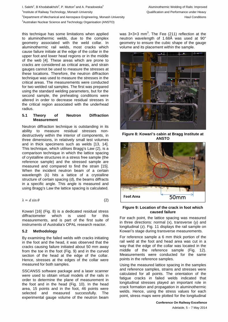
By examining the failed welds with cracks initiating in the foot and the head, it was observed that the cracks causing failure initiated about 50 mm away from the toe in the foot (Fig. 9) and in the curved section of the head at the edge of the collar. Hence, stresses at the edges of the collar were measured for both samples.
SSCANSS software package and a laser scanner were used to obtain virtual models of the rails in order to determine the plane of measurement in the foot and in the head (Fig. 10). In the head area, 15 points and in the foot, 46 points were selected and measured successfully. The experimental gauge volume of the neutron beam
was 3×3×3 mm3. The Feα (211) reflection at the neutron wavelength of 1.68Å was used at 90° geometry to ensure the cubic shape of the gauge volume and its placement within the sample.
Figure 8: Kowari’s cabin at Bragg Institute at
ANSTO
Figure 9: Location of the crack in foot which caused failure
For each point, the lattice spacing was measured in three directions: normal (x), transverse (y) and longitudinal (z). Fig. 11 displays the rail sample on Kowari’s stage during transverse measurements.
For reference sample a 6 mm thick portion of the rail weld at the foot and head area was cut in a way that the edge of the collar was located in the middle of the reference sample (Fig. 12). Measurements were conducted for the same points in the reference samples.
Using the measured lattice spacing in the samples and reference samples, strains and stresses were calculated for all points. The orientation of the fatigue cracks in failed welds indicated that longitudinal stresses played an important role in crack formation and propagation in aluminothermic welds. Hence, using the stress values for each point, stress maps were plotted for the longitudinal

I. Salehi1, B Khodabakhshi2, P. Mutton1 and A. Paradowska3 Aluminothermic Welding of Rails: Improved 1Institute of Railway Technology, Monash University Qualification and Performance under Heavy 2Department of Mechanical and Aerospace Engineering, Monash University Haul Conditions 3Australian Nuclear Science and Technology Organisation (ANSTO)
Conference On Railway Excellence
Adelaide, 5 – 7 May 2014
direction (along the rail) for both samples in order to investigate the correlation between preheating and magnitude of residual stresses.
Figure 10: Plane of measurement (a) in the foot area, (b) in the head area
Figure 11: Rail sample on Kowari’s stage
during transverse measurement
Figure 12: Reference samples which are 6mm thick portions of the rail weld in the foot and
head
5.3 Stress Contours
Figures 13 and 14 display the contour of longitudinal stresses in the foot and head of rail 1 and 2 respectively. Weld 1 is the sample with standard preheating condition, while for weld 2; the preheating conditions was altered by using an revised tip design for the preheating torch.
By comparing the stress contours, it is observed that stresses in the underhead region decreased significantly with the revised preheating conditions. However, in the foot area, the stresses slightly increased. Moreover, it can be seen that stresses in the head are not symmetrical for the second sample. These results are consistent with the flame pattern obtained with the new tip design, which was intended to apply more heat to the underhead region and less to the foot area. Furthermore, during the welding process for the second sample, the technician noticed that the flame was inclined toward one side of the rail in the head area which resulted in one side receiving more heat. This is the reason for uneven stress distribution in the head of the second sample.
These results obtained with the revised preheating conditions are very encouraging, as they confirmed that the residual stress levels in this region could be improved, albeit with a slight increase in the corresponding stresses in the foot region.
Further experimental work is being undertaken to determine the effect of the revised preheating conditions on the position of the fusion boundary relative to the edge of the weld collar, and the
z
z
y
y
x
x
(a)
(b)

I. Salehi1, B Khodabakhshi2, P. Mutton1 and A. Paradowska3 Aluminothermic Welding of Rails: Improved 1Institute of Railway Technology, Monash University Qualification and Performance under Heavy 2Department of Mechanical and Aerospace Engineering, Monash University Haul Conditions 3Australian Nuclear Science and Technology Organisation (ANSTO)
Conference On Railway Excellence
Adelaide, 5 – 7 May 2014
hardness levels in this region, both of which also influence the fatigue characteristics of welds [2].
Figure 13: Longitudinal stress contour in the
foot area for weld 1 and 2
Figure 14: Longitudinal stress contour in the
head area for weld 1 and 2
6. IMPROVING IN-TRACK WELDING PROCEDURES
Analysis of the failure (i.e. broken rail) statistics associated with aluminothermic welds under heavy haul conditions indicates that over 50% of all failures occur in 6 months or less from the date of weld installation, and approximately 75% before the weld is 12 months old (Fig. 15). These early failure statistics indicate that premature failure of welds can be associated with defects arising from use of incorrect welding procedures. Subsequent metallurgical examination of failed welds has confirmed a number of defective weld conditions, including:
• hot tears and shrinkage cracks arising from incorrect positioning of the preheating torch in the mould cavity,
• incorrect weld gap, • mould not aligned and fitted or sealed
correctly.
Figure 15: Distribution of age of weld at failure
The more demanding service conditions in heavy haul systems are such that any shortcomings in weld quality, such as those identified in failed welds, will lead to premature failure. For this reason, mobile flashbutt welding is being increasingly used to replace aluminothermic welding. However it is currently not possible to eliminate the use of the latter, for example around switched and turnouts, or for emergency repair of broken rail. For this reason, an enhanced welder training and audit program was developed and implemented to improve welder competency levels. The program included detailed training in both theoretical and practical aspects of the welding process being used, regular auditing and assessment of welding procedures, and mandatory requirement for re-accreditation after a 2-year period. The ongoing audit program also provides the opportunity to identify and address any issues with consumables or equipment, such that these can be addressed in conjunction with the consumable supplier.
7. CONCLUSIONS
Aluminothermic welds continue to be widely used across the rail industry for in-track welding; however the performance and in particular reliability of this weld type under high axle load conditions is often inconsistent and variable compared to that obtained with flashbutt welds.
A number of activities are being undertaken in order to overcome some of the inherent limitations of this welding process. The development and application of a fatigue analysis methodology, previously undertaken by one of the authors, has demonstrated that it is possible to provide a quantitative comparison of the fatigue behaviour of alternative aluminothermic welding procedures. Further development of this methodology is possible using more accurate residual stress data
Weld 1
Weld 2
Weld 1
Weld 2

I. Salehi1, B Khodabakhshi2, P. Mutton1 and A. Paradowska3 Aluminothermic Welding of Rails: Improved 1Institute of Railway Technology, Monash University Qualification and Performance under Heavy 2Department of Mechanical and Aerospace Engineering, Monash University Haul Conditions 3Australian Nuclear Science and Technology Organisation (ANSTO)
Conference On Railway Excellence
Adelaide, 5 – 7 May 2014
for critical regions of the weld. In addition, these measurements have demonstrated that it is possible to reduce residual stress levels in critical regions of the weld by altering the preheating conditions.
The existing qualification requirements for aluminothermic welds do not currently address on fatigue failure mode which occurs under heavy haul conditions. A fatigue test methodology for the underhead region is therefore under development; once completed, it is anticipated that this will be incorporated into the prequalification requirements for weld types intended for use under these demanding conditions.
The performance of newly-installed welds is strongly dependent on weld quality, which is often compromised by failure to adhere to the specified welding procedures. Premature failure of such welds can therefore be expected. These issues can be addressed by improved welder competency levels, achieved via more rigorous training and accreditation, and ongoing auditing of welding procedures.
8. ACKNOWLEDGEMENTS
This paper is partially based on research activities undertaken on behalf or BHP Billiton Iron Ore Pty Ltd, and Rio Tinto Iron Ore. The authors thank these organisations for their support of the activities undertaken at the Institute of Railway Technology.
The authors acknowledge the support of:
• The Bragg Institute, Australian Nuclear Science and Technology Organisation, in providing the neutron research facilities used in this work.
• Railtech Australia Ltd for their contribution to the manufacturing of their specimens.
One of the authors (BK) acknowledges the financial support of AINSE and Institute of Railway Technology, Monash University.
The authors also wish to acknowledge the significant contribution of Mr John Alserda, formerly of the Institute of Railway Technology, in the development and conduct of the welder training and audit program, and to other activities undertaken by the Institute to improve the reliability of aluminothermic welds in heavy haul systems. John passed away suddenly and unexpectedly in September 2013.
9. REFERENCES
[1]. Mutton PJ, Alvarez EF. Failure modes in aluminothermic rail welds under high axle load conditions. Engineering Failure Analysis. 2004;11:151-66.
[2]. Chen Y, Lawrence FV, Barkan CPL, Dantzig JA. Weld defect formation in rail thermite
welds. Proceedings of the Institution of Mechanical Engineers -- Part F -- Journal of Rail & Rapid Transit: Professional Engineering Publishing. 2006;220:373-84.
[3]. Mutton P J and Soeleiman S. Performance of aluminothermic welds under high axle loads, Proc. 4th Int. Heavy Haul Railway Conference, IEAust, 1989.
[4]. Salehi I, Kapoor A, Mutton P. Multi-axial fatigue analysis of aluminothermic rail welds under high axle load conditions. International Journal of Fatigue. 2011;33:1324-36.
[5]. Salehi I, Kapoor A, Mutton PJ, Alserda J. Improving the reliability of aluminothermic rail welds under high axle load conditions. Rail Rejuvenation and Renaissance Conference on Railway Engineering (CORE 2010). Wellington, New Zealand 2010. p. 16-24.
[6]. Salehi I, Mutton P, Kapoor A. Analysis of damaging factors in thermite welds through multi-axial fatigue criterion. International Heavy Haul Association Conference 2011. Calgary, Canada; June 19-22, 2011.
[7]. Ekberg A, Bjarnehed H, Lundbéan R. A fatigue life model for general rolling contact with application to wheel/rail damage. Fatigue & Fracture of Engineering Materials & Structures. 1995;18:1189-99.
[8]. Salehi I, Mutton P, Kapoor A. Analysis of straight break formation in aluminothermic rail welds under heavy axle load conditions. International Heavy Haul Association Conference 2013. New Delhi, India. February 4-6, 2013.
[9]. BS EN 14730-1, Railway applications, Track, Aluminothermic welding of rails, Approval of welding processes. BSI British Standards; 2010.
[10]. AS 1085.20, Railway track material Part 20: Welding of steel rail. Standards Australia; 2012.
[11]. Tawfik D, Kirstein O, Mutton P J, Chiu W K. Verification of residual stresses in flash butt welded rails, Physica B. 2006; 385–386:894–96.
[12]. Mutton P J, Cookson J and Chui W K. Fatigue behaviour of flashbutt welds in high strength, eutectoid and hypereutectoid rail steels under high axle loads. Proceedings International Heavy Haul Association Conference 2011, Calgary, Canada, June 2011.
[13]. Hutchings MT, Krawitz AD. Measurement of residual and applied stress using neutron diffraction. NATO ASI Series 216E, Kluwer Academic Publishers, Dordrecht/ Boston / London, 1992.
I. Salehi1, B Khodabakhshi2, P. Mutton1 and A. Paradowska3 Aluminothermic Welding of Rails: Improved 1Institute of Railway Technology, Monash University Qualification and Performance under Heavy 2Department of Mechanical and Aerospace Engineering, Monash University Haul Conditions 3Australian Nuclear Science and Technology Organisation (ANSTO)
Conference On Railway Excellence
Adelaide, 5 – 7 May 2014
[14]. Price J, Paradowska A. Comparison of experimental and theoretical residual stresses in welds: The issue of gauge volume, International Journal of Mechanical Science. 2008;50:513-21
[15]. Rossini N. Methods of measuring residual stresses in components, International Journal of Material and Design. 2012;35:572-88.
[16]. Kirstein O. Kowari-OPAL’s residual stress diffractometer and its application to material science and engineering, Advanced Materials Research. 2008;41-42:439-44.