Allocation of Design Responsibilities in Constructional...
16
BCSA Publication No. 45/07 Allocation of Design Responsibilities in Constructional Steelwork FOR BUILDINGS
Transcript of Allocation of Design Responsibilities in Constructional...
BCSA Publication No. 45/07
Allocation of DesignResponsibilities inConstructionalSteelwork
FOR BUILDINGSBCSA Limited, 4 Whitehall Court, Westminster, London SW1A 2ESTelephone: +44 (0) 20 7839 8566 Fax: +44 (0) 20 7976 1634Web: www.SteelConstruction.org Email: [email protected]
E136 Orange Book Cover 8/11/07 08:36 Page 1
BCSA Publication No. 45/07
Allocation of DesignResponsibilities inConstructionalSteelwork
FOR BUILDINGS
E136 Orange book text pages V2 8/11/07 08:37 Page 1
HSE is pleased to support this publication which addresseshow the design of structural steelwork can be bettercoordinated by the effective supply of information to all thoseparties involved in the design and delivery of projects
Endorsed by:
Publication Number 45/07
ISBN 1-85073-554-9978-1-85073-554-0
British Library Cataloguing-in-Publications DataA catalogue record for this book is available from the British Library
© BCSA, ACE, Griffiths and Armour, SCI, CC, ACA and IStructE October 2007Reproduction of the text is authorised provided it is without amendment andthe source is acknowledged; reproduction of the checklists is authorisedprovided the source is acknowledged.
2
ACKNOWLEDGEMENTS
AcknowledgementsThis publication has been prepared under the guidance of a steeringcommittee composed of the representatives and organisations listed below:
Chairman Mr G Badge, Emmett Fabrications LtdBCSA Mr R Sharples, SIAC Tetbury Steel LtdAssociation for Consultancy Mr J Rushton, Peter Brett Associatesand Engineering Mr R BrickwoodGriffiths & Armour Mr E MacGregorSteel Construction Institute Mr D BrownConstruction Confederation Mr M Richards, MR1 Consulting LtdAssociation of Consultant Architects Mr T Brown, GMW ArchitectsInstitution of Structural Engineers Mr F Weare
Compiler Dr D Moore, BCSACompiler Mrs M Rich, BCSA
The steering committee acknowledges further advice provided by:
CIC Scope of Services group Mr D Storer, Arup Mr A Broomhead, ArupMrs F Paterson, CIC
NSSS Review Group Mr A Pillinger, Bourne Engineering Ltd Dr R Pope, Roger Pope Associates
Construction Confederation Mr J Peters
Association for Consultancy and Engineering Ms N Fung
Care has been taken to obtain the views and comments ofall sections of the industry including architects, consultingengineers, main contractors and steelwork contractors. The steering group acknowledges with thanks the helpfulcontributions made.
ACA is the national professionalbody representing architects inprivate practice throughout theUK representing some of thecountry's leading practices.
ACE represents some 45,000technical and fee earning staff inthe consultancy and engineeringsector working in the built andnatural environment.
BCSA is the national organisationfor the steel construction industry:its Members undertake design,fabrication and erection for allforms of construction.
The Construction Confederation is the main representativeorganisation for building and civilengineering contractors within the UK construction industry.
Griffiths and Armour are insurance advisers to theconstruction industry with aspecialisation in ProfessionalIndemnity Insurance.
The Institution of StructuralEngineers is the world’s leadingprofessional body for structuralengineering in the builtenvironment
SCI develops and promotes the effective use of steel inconstruction. It is an independentmembership based organisation.
E136 Orange book text pages V2 8/11/07 08:37 Page 2
CONTENTS
33
Page
1.0 Introduction 5
2.0 Definitions and References 6
2.1 Definitions
2.2 References
3.0 Using this Publication 7
3.1 Background
3.2 Design Co-ordination
3.3 Design Stages
3.4 Drawings, Dimensions and Activities
4.0 The Checklists 9
4.1 Background
4.2 Using the Checklists
4.3 Project Directory
4.4 Design Stage 1 Checklist
4.5 Design Stage 2 Checklist
Contents
E136 Orange book text pages V2 8/11/07 08:37 Page 3

5
INTRODUCTION
Accurate, timely and comprehensive information, especiallydesign information, is essential to all parties involved in aconstruction Project. To achieve this, everyone throughout thesupply chain needs to understand exactly what they have to do,the level of detail required and the dates by which information is tobe provided. Unfortunately, on many Projects these proceduresare either not properly established or are poorly managed. Bothproduction of information and its exchange need to be improvedin order to reduce wastage and overruns and to enable the Projectteam to deliver improving services to Clients. This applies just asmuch to Projects incorporating Steelwork as to any other.
Usually, the process of establishing production and exchange ofinformation will be one of dialogue between the various Projectparticipants involved in the design and delivery of the Project - aprocess made easier when Project teams are assembled in acollaborative way but possible and indeed common in traditionallyprocured Projects.
The early identification of design requirements is the easiest wayof avoiding late variations, which are always expensive. Steelworkis produced by a factory based manufacturing process that ishighly mechanised and increasingly automated. Consequently,Steelwork manufactured in the factory tends to be made veryefficiently, a process that is difficult to reproduce on site. Forinstance, it is estimated that a hole drilled in the factory costs afew pence yet the same hole drilled on site once the steel iserected can cost several hundred pounds, the reason being thatwork on site often requires work to be carried out at height,requiring different equipment and more personnel, andrepresenting an increased safety risk. Much wastage can be cutout of the system if there is good information available from thestart, allowing as much fabrication as possible to be completed inthe factory. If this is not possible, the design team must make aclear decision that site works will be needed and the steelworkcontractor informed early in the project.
Additionally, the CDM Regulations provide the following:
‘Every designer shall in preparing or modifying a design whichmay be used in construction work in Great Britain avoidforeseeable risks to the health and safety of any person -
(a) carrying out construction work;
(b) liable to be affected by such construction work…’ (paragraph 11(3))
This publication will therefore be a useful tool for the CDM co-ordinator to ensure compliance with the CDM Regulations.
Exchange of information can take place by many different methods- extranet, CD, e-mail or hard copy. Only one method should beused on any given Project and the agreement of all the partiesshould be reached at the beginning of the Project as to themethods which will be used and the status of informationexchange by such methods. One efficient way to do this is by useof a collaborative controlled electronic publication managementenvironment such as a Project wide shared server, a Projectextranet or a web-based Electronic Publication ManagementSystem, such as the Avanti SMP.
Whatever methods are chosen, proper exchange of information atthe right time also aids proper planning leading to safer work onsite by minimising out of sequence working and the modificationworks that will often need to be carried out whilst working at height.
The purpose of this publication is to provide guidance foridentifying the requirements for the production and exchange ofaccurate, timely and detailed information for Projects involvingSteelwork. It includes a comprehensive list of design activities anddesign information requirements in the form of Checklists to assistin the procurement of Steelwork prior to and following theappointment of a Steelwork Contractor.
1. Introduction
E136 Orange book text pages V2 8/11/07 08:37 Page 5
6
DEFINITIONS AND REFERENCES
2.1 Definitions
In this publication, the following terms are used with the followingmeanings (any reference to documents or drawings includesdocuments or drawings in any format, electronic or paper includingComputer Aided Design format).
Architectural Design The architectural design of the Projectindicating the arrangement of the spacesand facilities and the materials andfinishes of the Project for which theSteelwork is required.
Base Plan Drawings Drawings indicating location of columnbases and details of Steelworkconnections to the foundation.
BSRIA Research organisation which publishes 'ADesign Framework for Building Services'.
CDM Co-ordinator Person appointed as the CDM co-ordinator under the CDM Regulations.
CDM Regulations The Construction (Design andManagement) Regulations 2007.
CIC Construction Industry Council, whichpublishes the CIC Scope of Services.
Client The organisation for whom a Project iscarried out.
Contractor A person appointed to manage and/orimplement the design (if required) andmanage or carry out the construction ofthe whole or part of the Project.
Design Co-ordination The gathering, co-ordination andcommunication of design information tothe Project team.
Erection Drawings Drawings, which may be derived from theSteelwork General Arrangement Drawings,showing details amplifying the informationgiven in the erection method statementprepared in accordance with the CDMRegulations and showing details of anytemporary Steelwork.
Fabrication Drawings Drawings showing all necessaryinformation required for the Steelworkfabrication element of the Project.
NSSS The National Structural SteelworkSpecification for Building Construction 5th Edition.
Project The proposed development procured or tobe procured by the Client as described inthe Architectural Design.
Project Specification The specification prepared for the Project.
Project Team The team procured or to be procured byor on behalf of the Client, to designprocure and implement the Project.
RIBA Royal Institute of British Architects, whichpublishes the Outline Plan of Work.
Safe Site Handover Certificate The Safe Site Handover Certificate
indicating that site conditions are suitableand adequate for the erection ofSteelwork.
SMP Avanti Standard Method and Procedure.
Steelwork Contractor The organisation appointed to undertakeany or all of the design, detailing,fabrication and erection of the Steelworkas required by the Project Specification.
Steelwork General Arrangement Drawings Fully dimensioned drawings showing the
location of all members together with theirsize and material grades, the forces to bedeveloped in their connections, anycambers and eccentricities and otherinformation necessary for the design of theconnections and completion of Fabricationand Erection Drawings.
Structural Engineering Drawings Drawings indicating the outline structural
requirements for the Project.
Steelwork Those parts of the Project described in theProject Specification as constructionalsteelwork
2.2 References
A Design Framework for Building Services. Published by BSRIApublication No. BG 6/2006; ISBN 0 86022 656 5
SMP Avanti Standard Method and Procedure. Published byConstructing Excellence available onwww.constructingexcellence.org.uk/resources/az/view.jsp?id=841
NSSS National Structural Steelwork Specification for BuildingConstruction 5th Edition. Published by BCSA and SteelConstruction Institute publication No. 203/07; ISBN 0 85073 052 X
RIBA Outline Plan of Work published by RIBA available onwww.architecture.com
The CIC Scope of Services. Published by CIC; ISBN 978 1 8594 6 258 4 available on www.cicservices.org.uk
The Construction (Design and Management) Regulations 2007 SI 2007 No. 320
Safe Site Handover Certificate. Published by BCSA available onwww.steelconstruction.org
2. Definitions and References
E136 Orange book text pages V2 8/11/07 08:37 Page 6
7
USING THIS PUBLICATION
3.1 Background
This publication is intended for anyone involved in a Project thatmay have an input into the exchange of information for the designand/or fabrication and/or erection of Steelwork. It is designed toassist in defining and managing the interfaces that exist in allconstruction Projects and in particular to minimising the potentialgaps and overlaps that may occur in the information supplied bythe parties involved in the procurement of Steelwork.
The following points are important to note:
1. This publication does not attempt to deal with liability for designwork, simply the practicalities of who does what design, when itis carried out and how information is distributed throughout theProject team.
2. This publication is intended to be used no matter whatprocurement route is chosen and therefore references to formsof contract and procurement routes have been avoided.
3. This publication is not a mandatory requirement on designersand Contractors. It needs to be specified as a requirement inthe Project by the Client and advisers for all participants in aSteelwork contract.
This publication is primarily designed as a supplement to ordetailed explanation of Tables 1.1 and 1.2 of the NSSS but canequally be used independently. Also, as far as possible, it hasbeen designed to be compatible with the CIC Scope of Servicesand the RIBA Outline Plan of Work. With regard to the CIC Scopeof Services, it provides a further level of detail, amplifying theSpecific Scope Schedule (which sets out primary designresponsibility for certain elements at various stages). Thispublication also fits in with BSRIA's 'A Design Framework forBuilding Services'.
The Checklists in Section 4 are intended to encourage discussionbetween those procuring and those supplying the Steelwork inorder to seek general agreement on the respective roles andresponsibilities of those engaged. This will include clear agreementon who will provide the information necessary to enable the design,detailing, manufacture, supply and erection of the Steelwork andthe timescales within which it should be provided.
The Checklists may be used as the basis for a set of agreementsbetween the Client and other parties as appropriate regarding theproduction and exchange of information for procuring theSteelwork, which should be reflected in each Project teammember's contract.
Appointments are not always made at the same time and socompleting the Checklists early in the procurement process maywell require allocating certain activities to as-yet unknown parties.These can simply be marked 'to be confirmed', and refined later asappointments are made. However, it is essential that allappointments making a contribution to the Steelwork are madewithin the timescales required by the Project. Depending on thenature of any later appointments, certain activities may have to bedone by parties that have already been appointed; in this case,roles and responsibilities may need to be re-defined.
The Checklists can also be used to identify activities which havenot yet been allocated to any Project team member. Here, theybecome part of the Project risk management process.
3.2 Design Co-ordination
It is important that the interfaces between different members of theProject team are clear with appropriate roles and responsibilitiesdefined and allocated. In particular, there is design coderequirement for one party to be clearly responsible for overseeingthat overall structural stability is achieved even though theSteelwork may only be a part of an overall structural systemsupplied by a range of contractors. In addition, the organisationtaking the lead on co-ordination between design and manufactureshould be clearly identified so that every member of the Projectteam can make informed decisions about its own role and costs.
Problems may also arise where there is a spatial conflict betweenthe Steelwork and other elements of the Project including buildingservices. These can be avoided by ensuring responsibility isallocated for the checking of spatial co-ordination. This is dealt within the Checklists.
3.3 Design Stages
This publication uses two design stages relating to the Steelwork:preliminary design and detailed design; these are called DesignStage 1 and Design Stage 2. The more detailed design stagesused in other publications - for instance the RIBA Outline Plan ofWork and the CIC Scope of Services are included here for the sakeof comparison.
Design Stage 1 is equivalent to RIBA Stage D - DesignDevelopment, Stage E - Technical Design and Stages G & H -Tender Documentation and Action or CIC Stage 3D DesignDevelopment.
Design Stage 2 is equivalent to RIBA Stage F -Production Information or CIC Stage 4D - Production Information.
By the end of Design Stage 2 all the information necessary tofinalise the Fabrication Drawings should be available and fixed.This includes any minor adjustments to dimensions aroundopenings for doors, windows etc. and addition of any requiredsecondary Steelwork members. Major additions or changesshould not be carried out during the period leading up to theinformation exchange date.
Any alterations in the design should be discussed and resolvedbefore the end of Design Stage 2, to enable the personundertaking the design of the Steelwork to finalise the SteelworkGeneral Arrangement Drawings. Required information exchangedates should be highlighted in the Steelwork Contractor'sconstruction programme and should be set to meet therequirements for the start date for the design, fabrication and/orerection of the Steelwork as required. On large Projects or onProjects where phasing is required, multiple exchange dates maybe appropriate.
The end of Design Stage 2 should be clearly shown on the Projectprogramme so that all parties are aware of the informationexchange dates that have been agreed.
Table 1 gives a description of the two Design Stages 1 and 2,together with the outputs expected at the end of each stage.
3. Using this Publication
E136 Orange book text pages V2 8/11/07 08:37 Page 7

8
USING THIS PUBLICATION
3.4 Drawings, dimensions and activities
The scope and detail of documentation required for the Steelworkwill vary widely from project to project depending on suchparameters as size, complexity, location and the project deliverysystem. However, in general, complete information should include:
• A clear description of the structural elements and the orientationand overall stability of the structural system, includingnecessary schedules, sections and details
• A clear specification for materials and workmanship specific tothe Project
• Co-ordination within the Steelwork documentation and withother Project documentation
• Dimensions for structural elements and for their location
• The relationship of the structure with adjacent non-structuralelements and finishes
• Governing codes, design loads and design criteria for variousstructural elements and materials as required by the codesand/or needed for flexibility in future use
• Identification of parts of the structure designed by others (thatis, not the Steelwork Contractor) and the clear design andperformance requirements for these parts
• Clearly defined quality assurance measures required for thestructure including Contractor quality control and independentinspection and testing (e.g. welding).
The NSSS may be used to identify additional workmanship andmaterial specific information.
The Steelwork General Arrangement Drawings should include:
• Details of assembly
• Material properties
• Sizes for all structural elements
• Dimensions required for the preparation of Fabrication Drawingsand the fabrication and erection of the Steelwork.
The essential elements necessary to arrive at structural dimensionsinclude:
• Overall building dimensions and gridlines
• Location of all structural elements with respect to gridlines
• Identification of position of edge of slab
• Structural floor elevations
• Top of steel levels
• Size of all framing members
• Adequate description of x-sections shapes
• Base level below finished floor level
• Setting out related to an agreed datum
• Camber requirements
• Structural wall thickness
• Services routing strategy including structural zone
• Required tolerances
• Cladding zones.
A reliable mechanism is needed for implementing andtracking any design changes. Drawing revisions should beclearly identified and fully and unambiguously describedwith dated revision number and 'clouding'. It is essential thatall changes are promptly identified and clearly documentedand issued to all parties to minimise their impact on bothcost and programme.
Table 1 Design Stages
Design Stage Summary of the main deliverables RIBA Outline Plan of Work/CIC Services Stage
Design Stage 1
Sufficient information, including initial design work and the identification of any significant risks
associated with the design to enable theSteelwork Contractor to cost the Steelwork.
RIBA Stages D, E and G & H CIC Stages 3D
Design Stage 2
Sufficient information to allow finalisation of the complete design of the Steelwork. The output is a set of finalised agreed
Steelwork General Arrangement Drawings.
RIBA Stage FCIC Stage 4D
E136 Orange book text pages V2 8/11/07 08:37 Page 8
9
THE CHECKLISTS
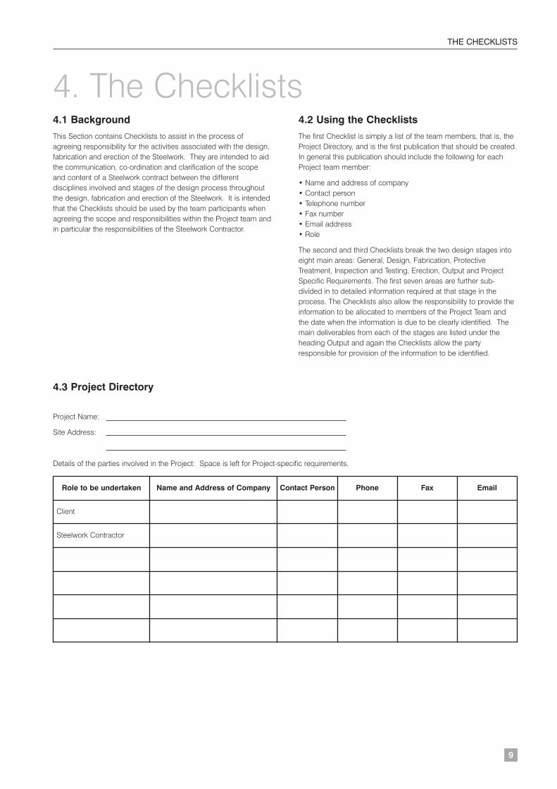
4.1 Background
This Section contains Checklists to assist in the process ofagreeing responsibility for the activities associated with the design,fabrication and erection of the Steelwork. They are intended to aidthe communication, co-ordination and clarification of the scopeand content of a Steelwork contract between the differentdisciplines involved and stages of the design process throughoutthe design, fabrication and erection of the Steelwork. It is intendedthat the Checklists should be used by the team participants whenagreeing the scope and responsibilities within the Project team andin particular the responsibilities of the Steelwork Contractor.
4.2 Using the Checklists
The first Checklist is simply a list of the team members, that is, theProject Directory, and is the first publication that should be created.In general this publication should include the following for eachProject team member:
• Name and address of company • Contact person• Telephone number• Fax number• Email address• Role
The second and third Checklists break the two design stages intoeight main areas: General, Design, Fabrication, ProtectiveTreatment, Inspection and Testing, Erection, Output and ProjectSpecific Requirements. The first seven areas are further sub-divided in to detailed information required at that stage in theprocess. The Checklists also allow the responsibility to provide theinformation to be allocated to members of the Project Team andthe date when the information is due to be clearly identified. Themain deliverables from each of the stages are listed under theheading Output and again the Checklists allow the partyresponsible for provision of the information to be identified.
4.3 Project Directory
Project Name:
Site Address:
Details of the parties involved in the Project: Space is left for Project-specific requirements.
4. The Checklists
Role to be undertaken Name and Address of Company Contact Person Phone Fax Email
Client
Steelwork Contractor
E136 Orange book text pages V2 8/11/07 08:37 Page 9
10
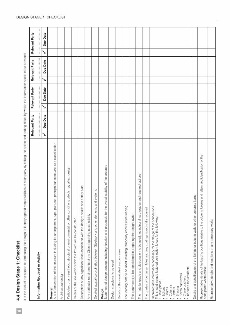
DESIGN STAGE 1: CHECKLIST4.
4 D
esig
n S
tag
e 1:
Ch
eckl
ist
It is
the
task
of t
he p
erso
n co
-ord
inat
ing
the
desi
gn to
iden
tify
agre
ed re
spon
sibi
litie
s of
eac
h pa
rty b
y tic
king
the
boxe
s an
d ad
ding
dat
es b
y w
hich
the
info
rmat
ion
need
s to
be
prov
ided
.
Rel
evan
t P
arty
Rel
evan
t P
arty
Rel
evan
t P
arty
Rel
evan
t P
arty
Info
rmat
ion
Req
uire
d o
r A
ctiv
ity...
......
......
......
......
....
......
......
......
......
....
......
......
......
......
....
......
......
......
......
...
✓D
ue D
ate
✓D
ue D
ate
✓D
ue D
ate
✓D
ue D
ate
Gen
eral
A b
rief d
escr
iptio
n of
the
stru
ctur
e in
clud
ing
its a
rran
gem
ent,
type
, pur
pose
, prin
cipa
l fun
ctio
ns a
nd u
se c
lass
ifica
tion
Arc
hite
ctur
al d
esig
n
Parti
cula
rs o
f any
aes
thet
ic, s
truct
ural
or e
nviro
nmen
tal o
r oth
er c
ondi
tions
whi
ch m
ay a
ffect
des
ign
Det
ails
of t
he s
ite w
ithin
whi
ch th
e P
roje
ct w
ill b
e co
nstru
cted
Des
crip
tion
of a
ny s
igni
fican
t ris
ks a
ssoc
iate
d w
ith th
e de
sign
; hea
lth a
nd s
afet
y pl
an
Any
par
ticul
ar re
quire
men
ts o
f the
Clie
nt re
gard
ing
sust
aina
bilit
y
Det
aile
d sp
atia
l co-
ordi
natio
n be
twee
n S
teel
wor
k an
d ot
her e
lem
ents
and
sys
tem
s
Des
ign
Sta
tem
ent o
f des
ign
conc
ept i
nclu
ding
func
tion
and
prop
osal
s fo
r the
ove
rall
stab
ility
of t
he s
truct
ure
Des
ign
stan
dard
s to
be
used
Det
ails
of t
he m
ain
stee
l sec
tion
size
s
The
load
ing
data
to b
e us
ed in
clud
ing
tem
pora
ry c
onst
ruct
ion
load
ing
The
para
met
ers
to b
e co
nsid
ered
in p
repa
ring
the
desi
gn la
yout
The
mat
eria
l gra
de a
nd d
esig
natio
n to
be
used
, inc
ludi
ng a
ll su
b gr
ades
and
requ
ired
optio
ns
The
grad
es o
f bol
t ass
embl
ies
and
any
coat
ings
spe
cific
ally
requ
ired
Rep
rese
ntat
ive
info
rmat
ion
nece
ssar
y fo
r the
des
ign
of th
e co
nnec
tions
. Th
is s
houl
d in
clud
e fa
ctor
ed c
onne
ctio
n fo
rces
for t
he fo
llow
ing:
• B
ase
plat
es•
Spl
ices
• B
eam
s•
Col
umns
• R
afte
rs•
Bra
cing
•
Eav
es c
antil
ever
s•
Cra
ne b
rack
ets
• Ti
e fo
rce
requ
irem
ents
Det
ails
and
spe
cific
atio
n of
the
fixin
gs o
r bol
ts to
wal
ls o
r oth
er c
oncr
ete
item
s
Rep
rese
ntat
ive
deta
ils o
f the
bra
cing
pos
ition
s re
lativ
e to
the
colu
mns
, bea
ms
and
rafte
rs a
nd id
entif
icat
ion
of th
e no
de p
oint
s w
here
crit
ical
Rep
rese
ntat
ive
deta
ils a
nd lo
catio
ns o
f any
tem
pora
ry w
orks
E136 Orange book text pages V2 8/11/07 08:37 Page 10
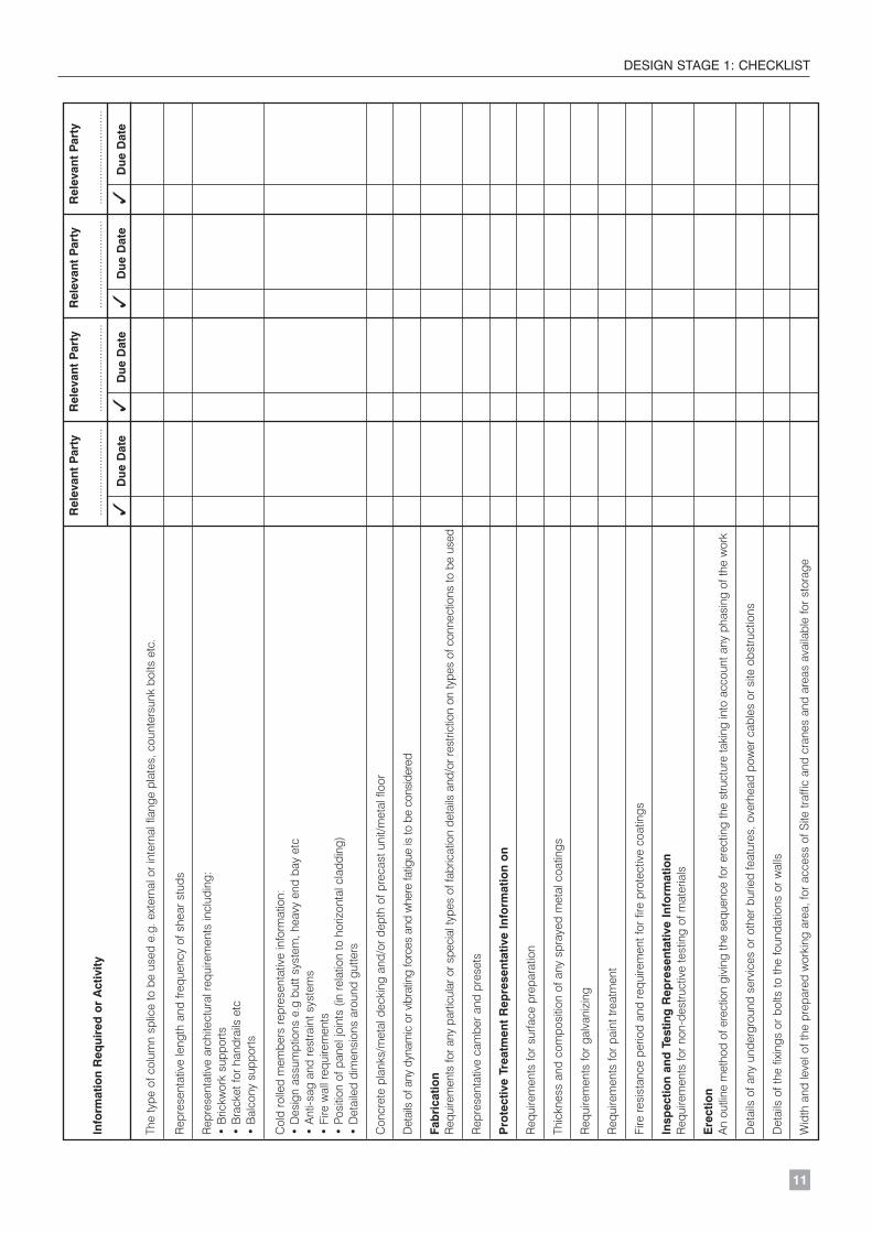
11
DESIGN STAGE 1: CHECKLISTR
elev
ant
Par
tyR
elev
ant
Par
tyR
elev
ant
Par
tyR
elev
ant
Par
ty
Info
rmat
ion
Req
uire
d o
r A
ctiv
ity...
......
......
......
......
....
......
......
......
......
....
......
......
......
......
....
......
......
......
......
...
✓D
ue D
ate
✓D
ue D
ate
✓D
ue D
ate
✓D
ue D
ate
The
type
of c
olum
n sp
lice
to b
e us
ed e
.g. e
xter
nal o
r int
erna
l fla
nge
plat
es, c
ount
ersu
nk b
olts
etc
.
Rep
rese
ntat
ive
leng
th a
nd fr
eque
ncy
of s
hear
stu
ds
Rep
rese
ntat
ive
arch
itect
ural
requ
irem
ents
incl
udin
g:•
Bric
kwor
k su
ppor
ts•
Bra
cket
for h
andr
ails
etc
• B
alco
ny s
uppo
rts
Col
d ro
lled
mem
bers
repr
esen
tativ
e in
form
atio
n:•
Des
ign
assu
mpt
ions
e.g
but
t sys
tem
, hea
vy e
nd b
ay e
tc•
Ant
i-sag
and
rest
rain
t sys
tem
s•
Fire
wal
l req
uire
men
ts•
Posi
tion
of p
anel
join
ts (
in re
latio
n to
hor
izon
tal c
ladd
ing)
• D
etai
led
dim
ensi
ons
arou
nd g
utte
rs
Con
cret
e pl
anks
/met
al d
ecki
ng a
nd/o
r dep
th o
f pre
cast
uni
t/met
al fl
oor
Det
ails
of a
ny d
ynam
ic o
r vib
ratin
g fo
rces
and
whe
re fa
tigue
is to
be
cons
ider
ed
Fab
rica
tion
Req
uire
men
ts fo
r any
par
ticul
ar o
r spe
cial
type
s of
fabr
icat
ion
deta
ils a
nd/o
r res
trict
ion
on ty
pes
of c
onne
ctio
ns to
be
used
Rep
rese
ntat
ive
cam
ber a
nd p
rese
ts
Pro
tect
ive
Trea
tmen
t R
epre
sent
ativ
e In
form
atio
n o
n
Req
uire
men
ts fo
r sur
face
pre
para
tion
Thic
knes
s an
d co
mpo
sitio
n of
any
spr
ayed
met
al c
oatin
gs
Req
uire
men
ts fo
r gal
vani
zing
Req
uire
men
ts fo
r pai
nt tr
eatm
ent
Fire
resi
stan
ce p
erio
d an
d re
quire
men
t for
fire
pro
tect
ive
coat
ings
Insp
ectio
n an
d T
estin
g R
epre
sent
ativ
e In
form
atio
nR
equi
rem
ents
for n
on-d
estru
ctiv
e te
stin
g of
mat
eria
ls
Ere
ctio
nA
n ou
tline
met
hod
of e
rect
ion
givi
ng th
e se
quen
ce fo
r ere
ctin
g th
e st
ruct
ure
taki
ng in
to a
ccou
nt a
ny p
hasi
ng o
f the
wor
k
Det
ails
of a
ny u
nder
grou
nd s
ervi
ces
or o
ther
bur
ied
feat
ures
, ove
rhea
d po
wer
cab
les
or s
ite o
bstru
ctio
ns
Det
ails
of t
he fi
s or
bol
ts to
the
foun
datio
ns o
r wal
ls
Wid
th a
nd le
vel o
f the
pre
pare
d w
orki
ng a
rea,
for a
cces
s of
Site
traf
fic a
nd c
rane
s an
d ar
eas
avai
labl
e fo
r sto
rage
E136 Orange book text pages V2 8/11/07 08:37 Page 11
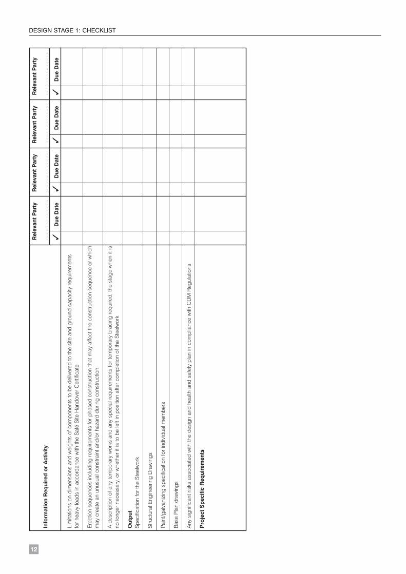
12
DESIGN STAGE 1: CHECKLISTR
elev
ant
Par
tyR
elev
ant
Par
tyR
elev
ant
Par
tyR
elev
ant
Par
ty
Info
rmat
ion
Req
uire
d o
r A
ctiv
ity...
......
......
......
......
....
......
......
......
......
....
......
......
......
......
....
......
......
......
......
...
✓D
ue D
ate
✓D
ue D
ate
✓D
ue D
ate
✓D
ue D
ate
Lim
itatio
ns o
n di
men
sion
s an
d w
eigh
ts o
f com
pone
nts
to b
e de
liver
ed to
the
site
and
gro
und
capa
city
requ
irem
ents
fo
r hea
vy lo
ads
in a
ccor
danc
e w
ith th
e S
afe
Site
Han
dove
r Cer
tific
ate
Ere
ctio
n se
quen
ces
incl
udin
g re
quire
men
ts fo
r pha
sed
cons
truct
ion
that
may
affe
ct th
e co
nstru
ctio
n se
quen
ce o
r whi
chm
ay c
reat
e an
unu
sual
con
stra
int a
nd/o
r haz
ard
durin
g co
nstru
ctio
n.
A d
escr
iptio
n of
any
tem
pora
ry w
orks
and
any
spe
cial
requ
irem
ents
for t
empo
rary
bra
cing
requ
ired,
the
stag
e w
hen
it is
no lo
nger
nec
essa
ry, o
r whe
ther
it is
to b
e le
ft in
pos
ition
afte
r com
plet
ion
of th
e S
teel
wor
k
Out
put
Spe
cific
atio
n fo
r the
Ste
elw
ork
Stru
ctur
al E
ngin
eerin
g D
raw
ings
Pain
t/gal
vani
zing
spe
cific
atio
n fo
r ind
ivid
ual m
embe
rs
Bas
e P
lan
draw
ings
Any
sig
nific
ant r
isks
ass
ocia
ted
with
the
desi
gn a
nd h
ealth
and
saf
ety
plan
in c
ompl
ianc
e w
ith C
DM
Reg
ulat
ions
Pro
ject
Sp
ecifi
c R
equi
rem
ents
E136 Orange book text pages V2 8/11/07 08:37 Page 12

13
DESIGN STAGE 2: CHECKLIST
Rel
evan
t P
arty
Rel
evan
t P
arty
Rel
evan
t P
arty
Rel
evan
t P
arty
Info
rmat
ion
Req
uire
d o
r A
ctiv
ity...
......
......
......
......
....
......
......
......
......
....
......
......
......
......
....
......
......
......
......
...
✓D
ue D
ate
✓D
ue D
ate
✓D
ue D
ate
✓D
ue D
ate
Gen
eral
A b
rief d
escr
iptio
n of
the
stru
ctur
e in
clud
ing
its a
rran
gem
ent,
type
, pur
pose
, prin
cipa
l fun
ctio
ns a
nd u
se c
lass
ifica
tion
Arc
hite
ctur
al d
esig
n
Parti
cula
rs o
f any
aes
thet
ic, s
truct
ural
or e
nviro
nmen
tal o
r oth
er c
ondi
tions
whi
ch m
ay a
ffect
des
ign
Det
ails
of t
he s
ite w
ithin
whi
ch th
e P
roje
ct w
ill b
e co
nstru
cted
Des
crip
tion
of a
ny s
igni
fican
t ris
ks a
ssoc
iate
d w
ith th
e de
sign
; hea
lth a
nd s
afet
y pl
an
Any
par
ticul
ar re
quire
men
ts o
f the
Clie
nt re
gard
ing
sust
aina
bilit
y
The
date
(s)
of is
sue
of th
e St
ruct
ural
Eng
inee
ring
Dra
win
gs o
r dat
a an
d ot
her i
nfor
mat
ion
Appr
oval
for a
ccep
tanc
e of
info
rmat
ion
subm
itted
by
the
Stee
lwor
k C
ontra
ctor
Det
aile
d sp
atia
l co-
ordi
natio
n be
twee
n S
teel
wor
k an
d ot
her e
lem
ents
and
sys
tem
s
Des
ign
Sta
tem
ent o
f des
ign
conc
ept i
nclu
ding
func
tion
and
prop
osal
s fo
r the
ove
rall
stab
ility
of t
he s
truct
ure
Des
ign
stan
dard
s to
be
used
Det
ails
of t
he m
ain
stee
l sec
tion
size
s
The
load
ing
data
to b
e us
ed in
clud
ing
tem
pora
ry c
onst
ruct
ion
load
ing
The
para
met
ers
to b
e co
nsid
ered
in p
repa
ring
the
desi
gn la
yout
The
mat
eria
l gra
de a
nd d
esig
natio
n to
be
used
, inc
ludi
ng a
ll su
b gr
ades
and
requ
ired
optio
ns
The
grad
es o
f bol
t ass
embl
ies
and
any
coat
ings
spe
cific
ally
requ
ired
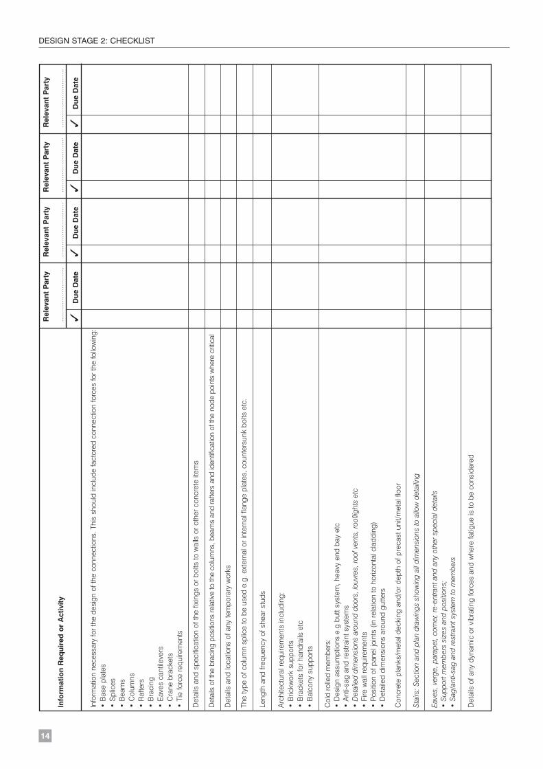
4.5
Des
ign
Sta
ge
2: C
hec
klis
t
It is
the
task
of t
he p
erso
n co
-ord
inat
ing
the
desi
gn to
iden
tify
agre
ed re
spon
sibi
litie
s of
eac
h pa
rty b
y tic
king
the
boxe
s an
d ad
ding
dat
es b
y w
hich
the
actio
n in
form
atio
n ne
eds
to b
e pr
ovid
ed.
Stag
e 2
incl
udes
all
info
rmat
ion
gath
ered
und
er S
tage
1 b
ut w
ith c
hang
es, q
ualif
icat
ions
and
any
add
ition
al d
etai
l cle
arly
iden
tifie
d. A
dditi
onal
info
rmat
ion
requ
ired
at S
tage
2 is
sho
wn
in it
alic
s.
E136 Orange book text pages V2 8/11/07 08:37 Page 13
14
DESIGN STAGE 2: CHECKLISTR
elev
ant
Par
tyR
elev
ant
Par
tyR
elev
ant
Par
tyR
elev
ant
Par
ty
Info
rmat
ion
Req
uire
d o
r A
ctiv
ity...
......
......
......
......
....
......
......
......
......
....
......
......
......
......
....
......
......
......
......
...
✓D
ue D
ate
✓D
ue D
ate
✓D
ue D
ate
✓D
ue D
ate
Info
rmat
ion
nece
ssar
y fo
r the
des
ign
of th
e co
nnec
tions
. Thi
s sh
ould
incl
ude
fact
ored
con
nect
ion
forc
es fo
r the
follo
win
g:•
Bas
e pl
ates
• S
plic
es•
Bea
ms
• C
olum
ns•
Raf
ters
• B
raci
ng
• E
aves
can
tilev
ers
• C
rane
bra
cket
s•
Tie
forc
e re
quire
men
ts
Det
ails
and
spe
cific
atio
n of
the
fixin
gs o
r bol
ts to
wal
ls o
r oth
er c
oncr
ete
item
s
Det
ails
of t
he b
raci
ng p
ositi
ons
rela
tive
to th
e co
lum
ns, b
eam
s an
d ra
fters
and
iden
tific
atio
n of
the
node
poi
nts
whe
re c
ritic
al
Det
ails
and
loca
tions
of a
ny te
mpo
rary
wor
ks
The
type
of c
olum
n sp
lice
to b
e us
ed e
.g. e
xter
nal o
r int
erna
l fla
nge
plat
es, c
ount
ersu
nk b
olts
etc
.
Leng
th a
nd fr
eque
ncy
of s
hear
stu
ds
Arc
hite
ctur
al re
quire
men
ts in
clud
ing:
• B
rickw
ork
supp
orts
• B
rack
ets
for h
andr
ails
etc
• B
alco
ny s
uppo
rts
Col
d ro
lled
mem
bers
:•
Des
ign
assu
mpt
ions
e.g
but
t sys
tem
, hea
vy e
nd b
ay e
tc•
Ant
i-sag
and
rest
rain
t sys
tem
s•
Det
aile
d di
men
sion
s ar
ound
doo
rs, l
ouvr
es, r
oof v
ents
, roo
fligh
ts e
tc•
Fire
wal
l req
uire
men
ts•
Posi
tion
of p
anel
join
ts (
in re
latio
n to
hor
izon
tal c
ladd
ing)
• D
etai
led
dim
ensi
ons
arou
nd g
utte
rs
Con
cret
e pl
anks
/met
al d
ecki
ng a
nd/o
r dep
th o
f pre
cast
uni
t/met
al fl
oor
Stai
rs: S
ectio
n an
d pl
an d
raw
ings
sho
win
g al
l dim
ensi
ons
to a
llow
det
ailin
g
Eave
s, v
erge
, par
apet
, cor
ner,
re-e
ntra
nt a
nd a
ny o
ther
spe
cial
det
ails
• Su
ppor
t mem
bers
siz
es a
nd p
ositi
ons;
• Sa
g/an
ti-sa
g an
d re
stra
int s
yste
m to
mem
bers
Det
ails
of a
ny d
ynam
ic o
r vib
ratin
g fo
rces
and
whe
re fa
tigue
is to
be
cons
ider
ed
E136 Orange book text pages V2 8/11/07 08:37 Page 14
DESIGN STAGE 2: CHECKLIST
15
Rel
evan
t P
arty
Rel
evan
t P
arty
Rel
evan
t P
arty
Rel
evan
t P
arty
Info
rmat
ion
Req
uire
d o
r A
ctiv
ity...
......
......
......
......
....
......
......
......
......
....
......
......
......
......
....
......
......
......
......
...
✓D
ue D
ate
✓D
ue D
ate
✓D
ue D
ate
✓D
ue D
ate
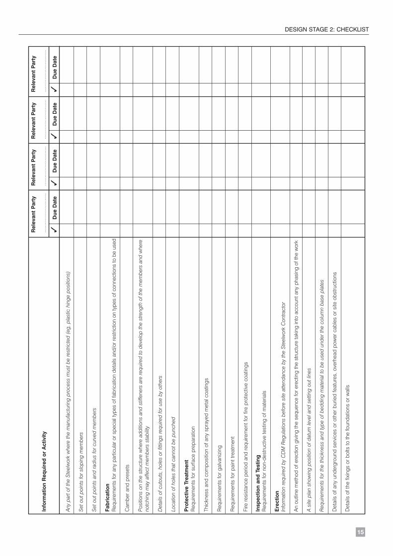
Any
part
of th
e St
eelw
ork
whe
re th
e m
anuf
actu
ring
proc
ess
mus
t be
rest
ricte
d (e
g, p
last
ic h
inge
pos
ition
s)
Set o
ut p
oint
s fo
r slo
ping
mem
bers
Set o
ut p
oint
s an
d ra
dius
for c
urve
d m
embe
rs
Fab
rica
tion
Req
uire
men
ts fo
r any
par
ticul
ar o
r spe
cial
type
s of
fabr
icat
ion
deta
ils a
nd/o
r res
trict
ion
on ty
pes
of c
onne
ctio
ns to
be
used
Cam
ber a
nd p
rese
ts
Posi
tions
on
the
stru
ctur
e w
here
add
ition
s an
d st
iffen
ers
are
requ
ired
to d
evel
op th
e st
reng
th o
f the
mem
bers
and
whe
reno
tchi
ng m
ay a
ffect
mem
bers
sta
bilit
y
Det
ails
of c
utou
ts, h
oles
or f
ittin
gs re
quire
d fo
r use
by
othe
rs
Loca
tion
of h
oles
that
can
not b
e pu
nche
d
Pro
tect
ive
Trea
tmen
t R
equi
rem
ents
for s
urfa
ce p
repa
ratio
n
Thic
knes
s an
d co
mpo
sitio
n of
any
spr
ayed
met
al c
oatin
gs
Req
uire
men
ts fo
r gal
vani
zing
Req
uire
men
ts fo
r pai
nt tr
eatm
ent
Fire
resi
stan
ce p
erio
d an
d re
quire
men
t for
fire
pro
tect
ive
coat
ings
Insp
ectio
n an
d T
estin
gR
equi
rem
ents
for n
on-d
estru
ctiv
e te
stin
g of
mat
eria
ls
Ere
ctio
nIn
form
atio
n re
quire
d by
CD
M R
egul
atio
ns b
efor
e si
te a
ttend
ance
by
the
Stee
lwor
k C
ontra
ctor
An
outli
ne m
etho
d of
ere
ctio
n gi
ving
the
sequ
ence
for e
rect
ing
the
stru
ctur
e ta
king
into
acc
ount
any
pha
sing
of t
he w
ork
A si
te p
lan
show
ing
posi
tion
of d
atum
leve
l and
set
ting
out l
ines
Req
uire
men
ts fo
r the
thic
knes
s an
d ty
pe o
f bed
ding
mat
eria
l to
be u
sed
unde
r the
col
umn
base
pla
tes
Det
ails
of a
ny u
nder
grou
nd s
ervi
ces
or o
ther
bur
ied
feat
ures
, ove
rhea
d po
wer
cab
les
or s
ite o
bstru
ctio
ns
Det
ails
of t
he fi
s or
bol
ts to
the
foun
datio
ns o
r wal
ls
E136 Orange book text pages V2 8/11/07 08:37 Page 15
DESIGN STAGE 2: CHECKLIST
16
Rel
evan
t P
arty
Rel
evan
t P
arty
Rel
evan
t P
arty
Rel
evan
t P
arty
Info
rmat
ion
Req
uire
d o
r A
ctiv
ity...
......
......
......
......
....
......
......
......
......
....
......
......
......
......
....
......
......
......
......
...
✓D
ue D
ate
✓D
ue D
ate
✓D
ue D
ate
✓D
ue D
ate
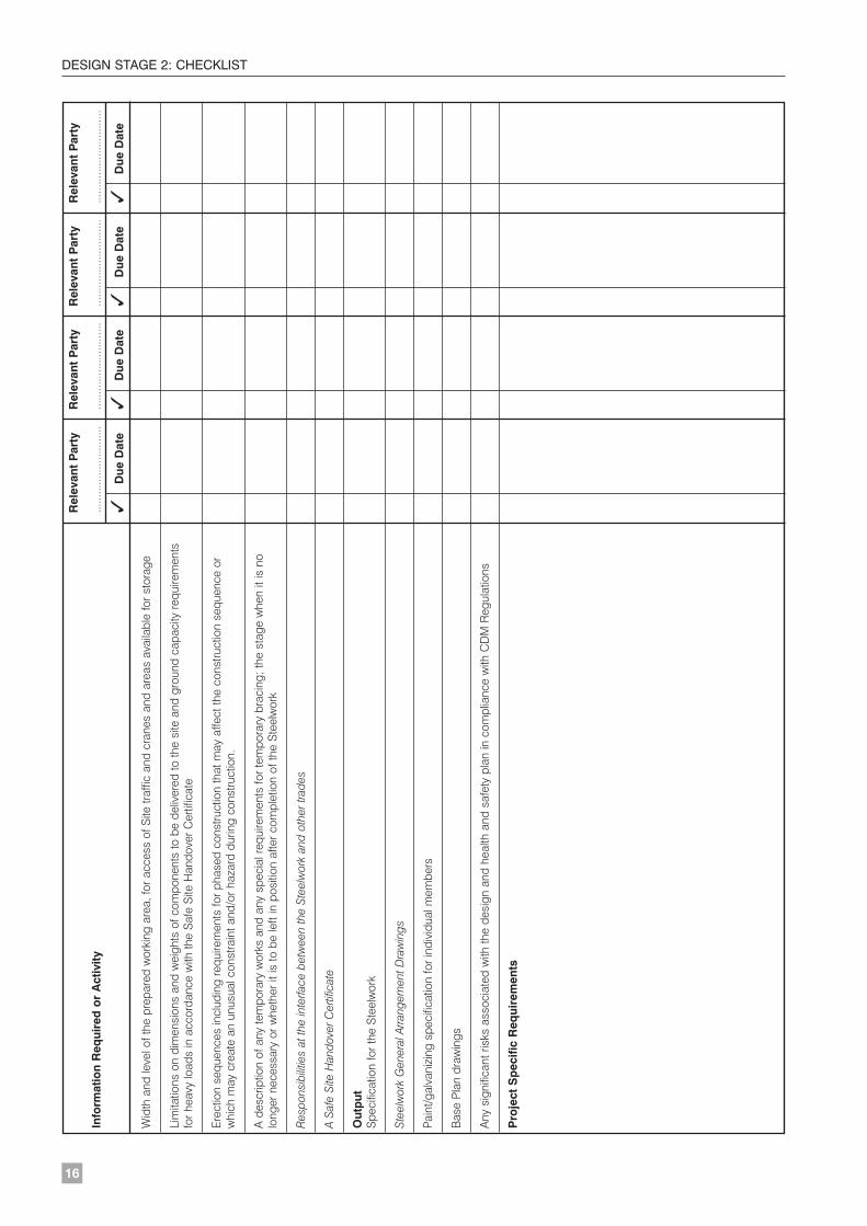
Wid
th a
nd le
vel o
f the
pre
pare
d w
orki
ng a
rea,
for a
cces
s of
Site
traf
fic a
nd c
rane
s an
d ar
eas
avai
labl
e fo
r sto
rage
Lim
itatio
ns o
n di
men
sion
s an
d w
eigh
ts o
f com
pone
nts
to b
e de
liver
ed to
the
site
and
gro
und
capa
city
requ
irem
ents
fo
r hea
vy lo
ads
in a
ccor
danc
e w
ith th
e S
afe
Site
Han
dove
r Cer
tific
ate
Ere
ctio
n se
quen
ces
incl
udin
g re
quire
men
ts fo
r pha
sed
cons
truct
ion
that
may
affe
ct th
e co
nstru
ctio
n se
quen
ce o
r w
hich
may
cre
ate
an u
nusu
al c
onst
rain
t and
/or h
azar
d du
ring
cons
truct
ion.
A d
escr
iptio
n of
any
tem
pora
ry w
orks
and
any
spe
cial
requ
irem
ents
for t
empo
rary
bra
cing
; the
sta
ge w
hen
it is
no
long
er n
eces
sary
or w
heth
er it
is to
be
left
in p
ositi
on a
fter c
ompl
etio
n of
the
Ste
elw
ork
Res
pons
ibili
ties
at th
e in
terfa
ce b
etw
een
the
Stee
lwor
k an
d ot
her t
rade
s
A Sa
fe S
ite H
ando
ver C
ertif
icat
e
Out
put
Spe
cific
atio
n fo
r the
Ste
elw
ork
Stee
lwor
k G
ener
al A
rrang
emen
t Dra
win
gs
Pain
t/gal
vani
zing
spe
cific
atio
n fo
r ind
ivid
ual m
embe
rs
Bas
e P
lan
draw
ings
Any
sig
nific
ant r
isks
ass
ocia
ted
with
the
desi
gn a
nd h
ealth
and
saf
ety
plan
in c
ompl
ianc
e w
ith C
DM
Reg
ulat
ions
Pro
ject
Sp
ecifi
c R
equi
rem
ents
E136 Orange book text pages V2 8/11/07 08:37 Page 16