
All-Russian Product Classifier Code 42 3200 Non-contact ...
30
Scientific Production Enterprise "TestElektro" All-Russian Product Classifier Code 42 3200 Non-contact Temperature Monitoring System "ZNOY" Instruction manual ZTE.348.003-07 RE Samara
Transcript of All-Russian Product Classifier Code 42 3200 Non-contact ...

Scientific Production
Enterprise "TestElektro"
All-Russian Product Classifier Code 42 3200
Non-contact Temperature Monitoring System
"ZNOY"
Instruction manual
ZTE.348.003-07 RE
Samara
TABLE OF CONTENTS
1 TECHNICAL DESCRIPTION AND PURPOSE .................................................... 2
1.1 Purpose ..................................................................................................................... 2
1.2 Technical data and characteristics ......................................................................... 4
1.3 Scope of supply ......................................................................................................... 6
1.4 Installation and operation ....................................................................................... 7
1.4.1 Mimic indication unit .......................................................................................... 7
1.4.2 Non-contact temperature monitoring ................................................................. 8
1.4.3. High voltage control system ................................................................................ 11
1.5 Programming ........................................................................................................... 15
1.6 Marking .................................................................................................................... 16
1.7 Packaging .................................................................................................................. 17
2 INTENDED USE ........................................................................................................ 18
2.1 General ..................................................................................................................... 18
2.2 Safety ......................................................................................................................... 19
3 HANDLING AND STORAGE .................................................................................. 20
Appendix A. Block diagram for connection of the device ........................................ 21
Appendix B. Electric connection diagram of the temperature monitoring unit ..... 22
Appendix C. Ordering code .......................................................................................... 23
Appendix D. Overall and installation dimensions of the unit ................................... 24
Appendix E. Overall and installation dimensions of the DTP-300 pyrometric sensor,
version 1 ......................................................................................................................... 25
Appendix F. Overall and installation dimensions of the pyrometric sensor DTP-300
version 2 .......................................................................................................................... 26
Appendix G. Overall and installation dimensions of the high voltage protection
switch ............................................................................................................................... 27
Appendix H. Overall and installation dimensions of the outside-mounted voltage
sensor .............................................................................................................................. 28
Appendix I. Overall and installation dimensions of the sub-insulation voltage sensor
.......................................................................................................................................... 29

1
Please read this instruction manual prior to operation This instruction manual (IM) is intended to introduce the principle and rules of
operation of multichannel non-contact temperature monitoring system "Znoy",
hereinafter referred to as "device".
The device is designed for use in switchgear cabinets of metal-clad installation
(KRU) or front-access assembly (KSO) type, or various industrial electrical
installations. It meets the technical requirements.
The reliability and durability of the device are provided not only by the quality of
development and manufacturing, but also by the conditions of handling, storage,
installation, commissioning and maintenance. Therefore, it is essential to comply
with all requirements of this instruction manual.
2
1. Technical description and purpose
1.1. Purpose.
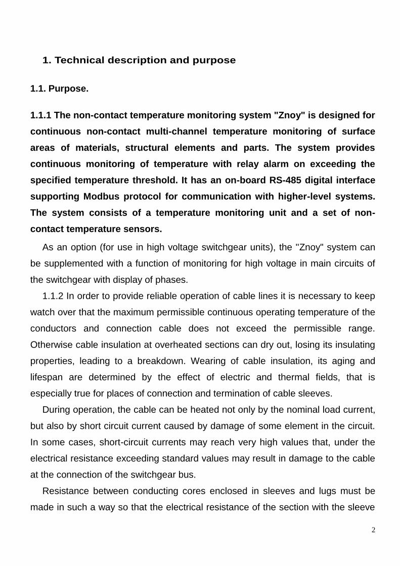
1.1.1 The non-contact temperature monitoring system "Znoy" is designed for
continuous non-contact multi-channel temperature monitoring of surface
areas of materials, structural elements and parts. The system provides
continuous monitoring of temperature with relay alarm on exceeding the
specified temperature threshold. It has an on-board RS-485 digital interface
supporting Modbus protocol for communication with higher-level systems.
The system consists of a temperature monitoring unit and a set of non-
contact temperature sensors.
As an option (for use in high voltage switchgear units), the "Znoy" system can
be supplemented with a function of monitoring for high voltage in main circuits of
the switchgear with display of phases.
1.1.2 In order to provide reliable operation of cable lines it is necessary to keep
watch over that the maximum permissible continuous operating temperature of the
conductors and connection cable does not exceed the permissible range.
Otherwise cable insulation at overheated sections can dry out, losing its insulating
properties, leading to a breakdown. Wearing of cable insulation, its aging and
lifespan are determined by the effect of electric and thermal fields, that is
especially true for places of connection and termination of cable sleeves.
During operation, the cable can be heated not only by the nominal load current,
but also by short circuit current caused by damage of some element in the circuit.
In some cases, short-circuit currents may reach very high values that, under the
electrical resistance exceeding standard values may result in damage to the cable
at the connection of the switchgear bus.
Resistance between conducting cores enclosed in sleeves and lugs must be
made in such a way so that the electrical resistance of the section with the sleeve

3
would not exceed the electric resistance of the entire length of the same core.
Failure to do so leads to local overheating of insulation of the sleeve during
operation of the cable line and its failure with cutting the power supply to
consumers. It is necessary that the operating temperatures (as well as the heating
temperature during short-circuit currents) at the connections or terminations do not
exceed the permissible values for cable cores.
This unit has a function of monitoring the temperatures of heating of cable cores
and connections.
1.1.3. In order to provide monitoring of high voltage in main current-carrying
circuits of switchgears, the device can optionally be equipped with high voltage
monitoring system (SKVN).
The system is designed to determine the presence or absence of voltage in
electrical AC installations with voltage from 6 to 35 kV, 50/60 Hz.
It includes the option of phasing and determining the difference of phasing
voltages of cables, overhead lines and transformers.
1.1.4. In order to communicate with higher-level systems, the unit has a built-in
RS-485 interface with Modbus protocol support;

4
1.2. Technical data and characteristics.
1.2.1. Designations of versions.
Designations of available versions of the device are given in the Annex D.
1.2.2. Basic technical characteristics are summarized in Table 1. Table №1. Basic technical characteristics of the device.
Parameter Value
Voltage of power supply and digital input signals, direct/alternating 120—370/85-265
Rated power for DC/AC current, W 3/15
Maximum number of channels for temperature measurement 15
Number of relay output channels 3
Rated operating voltage of terminals of relay output channels, DC/AC, V 220
Rated operating current of terminals of relay outputs, A 3
Parameters of sensors of the device
Maximum distance from the sensor to the measurement surface, mm 300
Optical ratio of distance to the object: Diameter of the spot 3:1
Measuring range of temperatures, °C -40…+300
Temperature hysteresis of the relay outputs, °C 10
Measurement error in measurement of temperature of black surface, °C ±4
Threshold voltage of the voltage sensors, % of Unom 60
Operating temperature range of the unit, °C -25…+60
Operating temperature range of the temperature sensor, °C -40…+60
Relative humidity, % 30—80
1.2.3. On customer's request, the device can be provided with 48V DC power
supply rated, and the voltage range of the power supply is from 36V to 72V DC.
1.2.4. Resistance of the insulation between all non-connected electric circuits of
the device, as well as between them and the case (except the connection to a PC)
is not less than 10 MΩ under normal climatic conditions.
1.2.5. Electrical insulation between all independent circuits of the device (except
the connection to a PC) can withstand test voltage 2000V (RMS) AC, 50 Hz
without breakdown or flashover of insulation for one minute.

5
1.2.6. Rated operating values of external mechanical factors are in compliance
to GOST17516.1-90 for M7 mechanical design group, including:
vibration load in the frequency range from 5 to 100 Hz with an
acceleration of 1g;
impacts with acceleration of 3g, number of impacts 10000;
seismic stability when exposed to acceleration of 3g in the frequency
range from 5 Hz to 15 Hz.
1.2.7. By climatic category, the devices complies with UHL.3.1 according to
GOST 15150-69 with the following specifications:
ambient temperature -40°C...+60°C;
relative air humidity up to 80% at a temperature of not more than +35°C
without condensation;
atmospheric pressure from 866 Pa (650 mm Hg) to 1067 Pa (800 mm
Hg);
type II atmosphere according to GOST 15150-69;
altitude above sea level no more than 1000 m;
not-explosive environment without any conductive dust, corrosive gases
and vapors in concentrations destroying metals and insulation.
1.2.8. It is allowed to expose the device in inoperative state to elevated
temperatures up to + 70°C, and after two hours of cooling down in normal ambient
conditions it would be suitable for use.
Operating position is any available.
1.2.9. The degree of protection of the case and terminals is IP20 according to
GOST 14254-96.
1.2.10. The average lifetime of the device is at least 25 years.
1.2.11. By means of protection from electric shock the device falls under the Class
0 in accordance with GOST 12.2.007.0-75.
1.2.12. The device is fireproof, fire safety is provided by using appropriate
materials.

6
1.3. Scope of supply
1.3.1. The scope of supply includes:
temperature monitoring unit "Znoy": 1 piece;
DTP-300 pyrometric temperature sensors - depending on the order;
SKVN high voltage control switch with a set of high voltage sensors -
depending on the order;
Jumper cables - depending on the order;
technical data sheet - one for each product or group of products;
Instruction Manual - in the amount specified in the order.
1.4. Installation and operation.
Block diagram of connection of the device is given in Appendix A.
1.4.1. Temperature monitoring unit.
In terms of construction, the device is designed in the form of a metal
housing with upper and lower connections of external conductors. The device is
equipped with a bracket for mounting on DIN rail. At the bottom of the device
there are: X3 connector for connection of power supply and grounding conductor.
X1, a relay output terminal for connection of external devices receiving alarm
commands. At the top of the device there are following terminals: X2 for
connection of additional external devices through RS-485 interface, X4 for
connection the bus line for temperature sensors and high voltage control switch.
Overall and installation dimensions of the unit are specified in Appendix D. The
unit has a robust metal housing. Installation is made in a cabinet on a DIN-rail
using a bracket.
1.4.1.3 Before starting and during operation the unit must be grounded through
terminal 1 of the connector X3 in the bottom part of the housing.
1.4.1.4 Connection blocks allow screw connection of one or two identical
conductors with common section up to 2.5 mm² and cross-section no less than 0.5

7
mm² each. Electric connection diagram of the temperature measurement unit is
given in Appendix B.
Connecting relay outputs installed in the X1 connector shall be conducted
according to the diagram in Appendix C: COM1 \ 2 \ 3 - common contact, NO1 \ 2 \
3 - normally open contact, NC2 \ 3 - normally closed contact.
1.4.2. Non-contact temperature monitoring.
1.4.2.1 DTP-300 pyrometric temperature sensors are used for continuous
non-contact temperature measurement of important areas of the main circuits of
the switchgear, such as high voltage terminals of a switch or circuit breaker,
busbar connections, junctions and terminating cable boxes. External view of
DTP-300 sensor is shown in Figure 1.
Each sensor is provided with a laser pointer for detection of center of the
measured spot on the surface. All measured temperature values are displayed
on the screen. The device is provided with three outputs
of "dry contact" type. Normally open output 1 (COM1,
NO1) is designed for signaling the presence of normal
connection with all programmed temperature sensors in
the circuit: when power is applied to the unit and upon
establishing communication with all sensors the output
Figure 1. External view of
DTP-300 sensor
8
1 is closed and remains closed at all times during operation of the device.
Opening of the output 1 occurs in case of continuous communication failure with
at least one of the temperature sensors for a period of more than 1 minute. The
function of the outputs 2 and 3 (break-make contacts COM2, NO2, NC2, COM3,
NO3, NC3) in the standard version of the device is to output signals to external
devices when the temperature exceeds the set thresholds in at least one of all
the temperature channels. In the standard version, the relays are configured with
positive logic, e.g. the relays are disabled at temperatures below the threshold
and enabled at temperatures above the threshold.
If necessary, on demand of the customer, the channels of the sensor can be
separated and attached to any of the relays.
It is recommended to set the triggering temperature of the relay 2 at the
maximum normalized temperature and use this value as an alarm for the
operator (control engineer), or as a function for using in a control device such as
a cooling fan. Setpoint for triggering the temperature relay 3 can be configured
as alarm value and used for the emergency shutdown of high voltage switch or
other actuator.
The customer can include the required number of temperature channels in the
order code to ensure proper control of contacts and connections in the cell.
Numbering and location of the sensors are identified in accordance with the
order code in Appendix B.
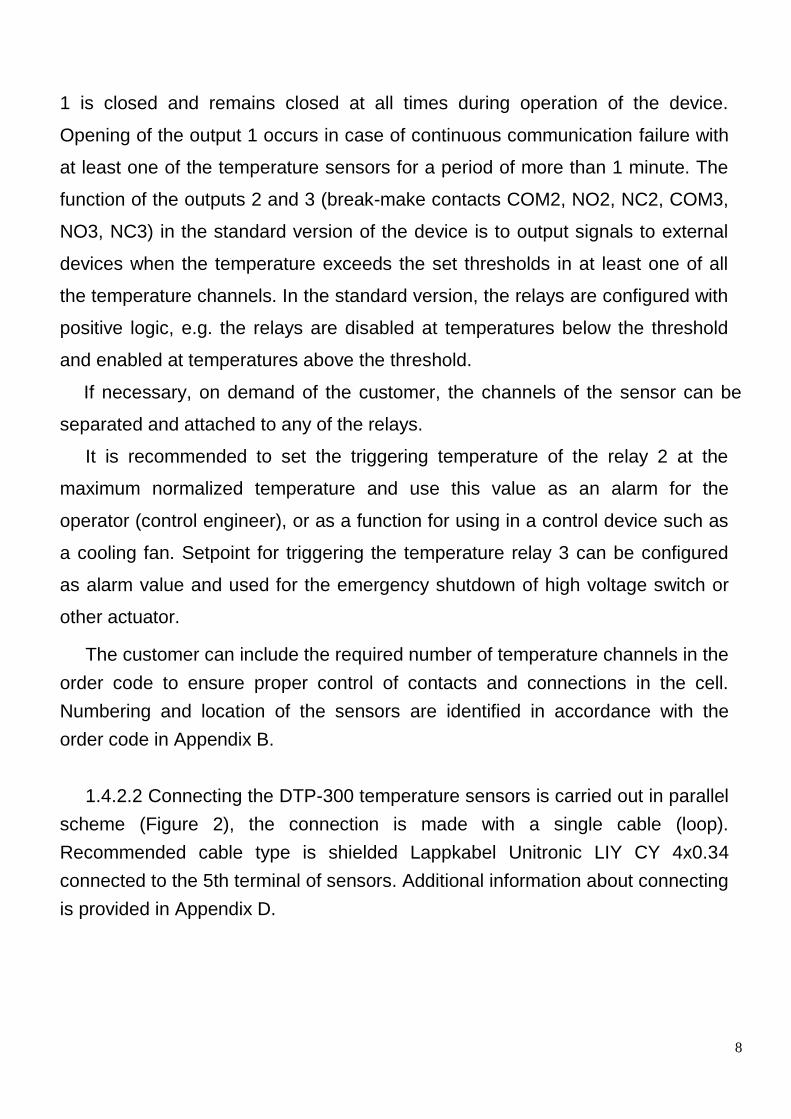
1.4.2.2 Connecting the DTP-300 temperature sensors is carried out in parallel
scheme (Figure 2), the connection is made with a single cable (loop).
Recommended cable type is shielded Lappkabel Unitronic LIY CY 4x0.34
connected to the 5th terminal of sensors. Additional information about connecting
is provided in Appendix D.
9
Figure 2. Electric connection diagram of the DTP-300 sensor.
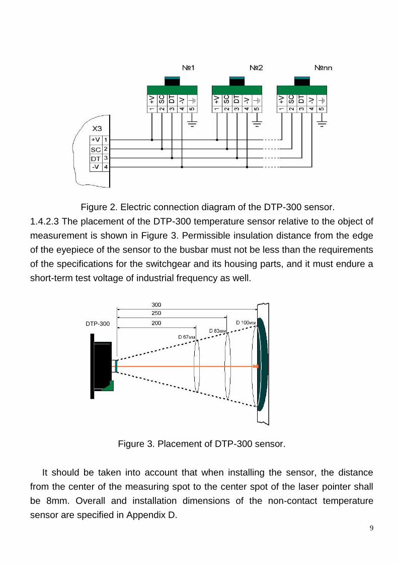
1.4.2.3 The placement of the DTP-300 temperature sensor relative to the object of
measurement is shown in Figure 3. Permissible insulation distance from the edge
of the eyepiece of the sensor to the busbar must not be less than the requirements
of the specifications for the switchgear and its housing parts, and it must endure a
short-term test voltage of industrial frequency as well.
Figure 3. Placement of DTP-300 sensor.
It should be taken into account that when installing the sensor, the distance
from the center of the measuring spot to the center spot of the laser pointer shall
be 8mm. Overall and installation dimensions of the non-contact temperature
sensor are specified in Appendix D.
DTP-300
10
1.4.2.4 The temperature sensor must be grounded through its base to the
housing of the structure with a electrical connecting washer and provided with a
metal contact to the housing of the switchgear.
1.4.2.5 To provide for the error of temperature measurement specified in the
Table 1 it is necessary to perform surface preparation prior to operation, as
different materials have different coefficients of thermal radiation in the range of
0.13 to 0.95.
In order to bring the heat emission factor at the surface of measurement to the
value close to one, the simplest solution is to cover the surface of the
measurement with a layer of black enamel PF115 with the diameter of the spot in
accordance with the ratio of the optical sensor and the distance from the sensor to
the surface. Examples of the relation between the distance and the diameter of the
measuring spot are shown in Figure №3.
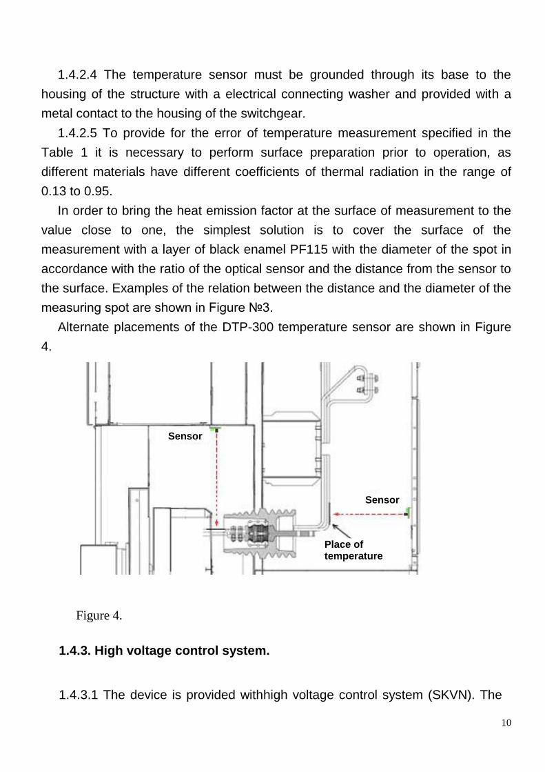
Alternate placements of the DTP-300 temperature sensor are shown in Figure
4.
1.4.3. High voltage control system.
1.4.3.1 The device is provided withhigh voltage control system (SKVN). The
Figure 4.
Sensor
Sensor
Place of temperature measurement
11
system consists of a switch and six high voltage sensors for monitoring the
voltage of phases A, B, C in busbars and phases A1, B1, C1 at the outgoing
lines.
The electrical connection diagram is displayed in Appendix A.
High voltage sensors connected to the busbars are the primary sensors,
serving as reference for phasing. They are marked with letters A, B, C.
High voltage sensors connected to the outgoing lines, generally located
outside the switching device. They are marked with letters A1, B1, C1.
1.4.3.2 High voltage sensors have two design versions.
1 - outside-mounted high voltage sensors installed in front of current-carrying
parts of the switchgear. This version is the same for the class of voltage from 6 to
35kV. Overall and installation dimensions of outside-mounted voltage sensors
are specified in Appendix G.
2 - sub-insulation high voltage sensors are mounted directly under the
supporting insulators of the switchgear. An appropriate voltage sensor is installed
for every voltage class taking into account the various design features of post
insulators. Overall and installation dimensions of sub-insulation voltage sensors
are specified in Appendix H.
Depending on the design of the switchgear, customer can choose any
convenient design version of the high voltage sensor with a prerequisite of the
selection of the same version for same location: busbars or outgoing line. The
distance between the sensors of phases A, B, C and A1, B1, C1 should be at
least 400mm.
1.4.3.3 Signals from all high voltage sensors are transmitted through a
shielded wire to the switch, which is located in a compartment of a switch
cabinet, busbar assembly cabinet or cable compartment. The switch provides
data for the temperature monitoring unit using noise-resistant four-wire interface.
This solution greatly simplifies installation process, improves the reliability and
safety of system operation. Temperature monitoring unit, in turn, processes the
12
data from the switch and writes the coded data about the presense of voltage
and phasing to the corresponding Modbus registers in a specific format.
Description of Modbus registers and data formats is contained in the Appendix I
of this instruction manual.
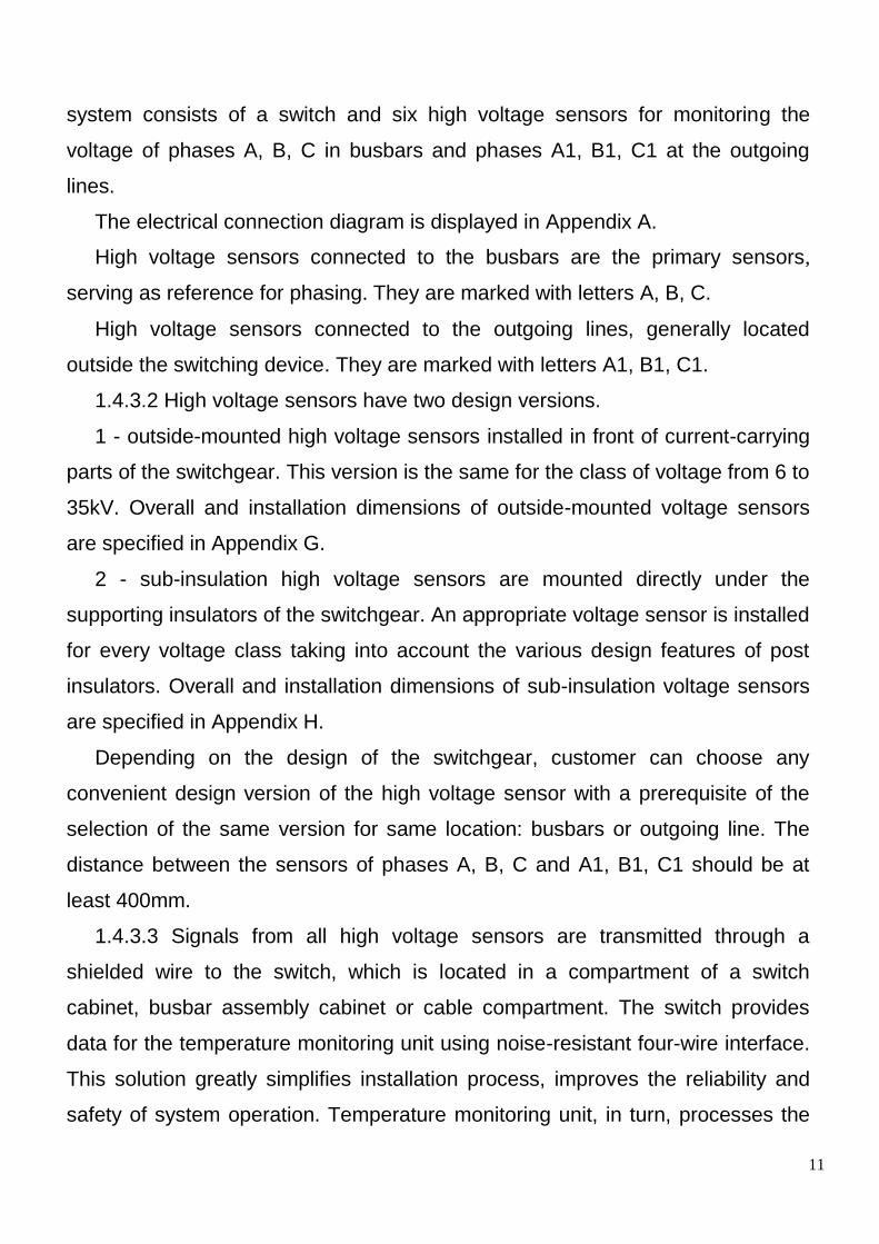
Figure 5. Exterior view of the high voltage protection (SKVN) switch.
1.4.3.4 Housing of the switch (Figure 5) must be grounded through the ground
conductor located near the side of the fastening holes, and it is necessary to
provide a connection to the metal housing of the switchgear. Overall and
installation dimensions of the SKVN switch are specified in Appendix F.
1.4.3.6 Using the high voltage control system SKVN it is possible to
perform "hot" phasing of cables, overhead lines and transformers. Phase A, B
and C are used as reference values in relation to which the phasing is carried
out. Appendix I lists the alternate values of the data registers of the Modbus
protocol for the temperature monitoring unit at incorrect line phasing.
1.4.3.7 In order to check the correctness of connection of high voltage
sensors of outside-mounted and sub-insulation types, it is necessary to touch the
termination pad of the central core at the right side of the device with a
conductive tool such as a screwdriver, holding the tool by the metal part. This will
cause a change in the sign of the respective phase in the Modbus register of the
temperature monitoring unit. This operation must be carried out for all phases.
In order to check the performance of the fully assembled high voltage control
system (SKVN) it is necessary to apply high voltage necessary to all main
circuits of the switchgear (by turning on the switching device and install shorting
13
between the phases A, B, C, or A1, B1, C1) at the level of 70% - 100% of the
nominal operating voltage of the switchgear. In such a case in the register
0x0030 (high voltage protection status) the flags for phases A, B, C would be set
to 1, and the display mode flag would be set to 0.
Qualification test of the high voltage control system must be conducted under
the Program and procedure for qualification tests ZTE.348.003-07 PM Section
4.6.
1.5. Communication interface RS-485
1.5.1. The temperature monitoring unit has an RS-485 interface with Modbus
protocol support for communication with external devices. With this protocol, the
user is able to obtain current data for all measured temperature values as well as
the encoded data on the presence of voltage and phasing. The protocol also
supports the options to change the user default settings, such as relay triggering
threshold, the number of sensors in the unit's network, and others.
1.5.2. Descriptions of protocol properties, registers, functions and data formats
are contained in Appendix I.
1.6. Marking
1.6.1. Marking of the device corresponds to the requirements of GOST 18620-
80 and design documentation.
On the front panel there are the following markings:
- Symbol (type) of the device;
- trademark;
On the back side of the case there are the following markings:
- rated supply voltage;
- digital and letter indication of input circuits;
- date of manufacture;
- serial number of the product.
- Number of the mimic corresponding to the switchgear (to be marked by
the customer after programming of the device)

14
1.6.2. The devices certified with GOST Certification System are marked with a
conformity mark in accordance with GOST 50460-92. Conformity mark is applied
to the device itself, packaging, container and shipping documentation near the
manufacturer's trademark.
1.6.3. Transport marking of the containers shall comply with GOST 14192-96,
including the markings of handling signs: "Fragile. Handle with care", "Protect from
moisture", "Temperature limitation" (the lower limit of the ambient temperature
during transportation and storage is -40°C). Marking shall be applied directly to the
container.
Marking shall be made with resistant paint, providing accuracy and readability
of labels during storage.
1.7. Packaging
1.7.1 Packaging of the devices is made in accordance with GOST 23216-78.
1.7.2 The device is not intended for long-term preservation.
1.7.3 The combination of types and variants of the shipping container with the
types of inner packaging is in accordance with GOST 23216-78.
1.7.3.1 The packaging for domestic application (except the Far North and
remote regions) in accordance with GOST 15150-69.
Packaging category KU-2. TK. VU-P-A
1.7.3.2 The packaging for domestic supply to the Far North and remote regions is
in accordance with GOST 15846-2002.
Packaging category KU-2. TK. ВУ-П-B
1.7.3.3 The devices are packaged into a box made of corrugated cardboard
according to GOST 7376-89 or cardboard under GOST 7933-89 in compliance
with the conditions that ensure their safety during handling and transportation.
Gross weight of the packed unit shall not exceed 0.9 kg.
Dimensions of the box should prevent free movement of devices in it. In case
of packaging of several devices in the same box the possibility of free movement
of devices inside the box must be prevented.
As may be agreed with the customer, the devices may be transported in
containers according to GOST 18477-79 with the additional requirements of
GOST 20259-80, with the permitted packaging of the devices in corrugated

15
cardboard according to GOST 7376-89.
1.7.3.4 Packaging of technical and accompanying documentation and marking
of the packages are made according to the requirements of GOST 23216-78.
1.7.3.5 Inner packaging and shipping container are allowed to be made only
according to the manufacturer's drawings.

16
2. Maintenance and repair.
2.1 General information
2.1.1 Operation and maintenance of the device must be carried out according to
this Instruction Manual under the environment conditions specified in this
document.
2.1.2 The possibility of operation the device under conditions other than those
specified should be agreed with the holder of original design documentation and
the manufacturer.
The reliability and durability of the devices in the equipment are provided not
only by the quality of the devices themselves, but also by the right choice of modes
and conditions of their operation, i.e. compliance with the requirements set out in
this Instruction Manual.
2.1.3 In all cases of operation it is recommended to take measures to ensure
improved ventilation and rational placement of the device.
2.1.3 Accuracy of installation of the device shall be checked by visual
inspection.
2.1.4 Checkup of the temperature sensors and connections for operation
capacity according to their number is conducted against the temperature values in
the registers of the unit temperature monitoring protocol. In order to do this, it is
recommended to put any object with a temperature different from ambient
temperature, e.g., palm of the hand, to every sensor in the succession at a
distance of 10-30 cm, and observe changes in temperature. In case of wrong
arrangement of sensors it is necessary to rearrange them according to the
Appendix to the technical data sheet of the indicator.
2.1.5 The temperature sensor is an optical device, and any significant dust
contamination should be cleared with compressed air.

17
2.1.6 Dismantling of the device installed into equipment must be carried out
without deformation and mechanical damage to the device housing.
2.1.7 Repairs to the device must be carried only by specialists of the holder of
original design documentation and the manufacturer.
Analysis and dismantling of inoperable devices shall be performed only by
the manufacturer. Repair or replacement of the defective unit would be made
on the basis of warranty.
2.2. Safety precautions
2.2.1 During operating and testing of the device it is necessary to comply with
the "Regulations for Operation of Consumer Electrical Installations," as well as the
requirements of this Instruction Manual.
2.2.2 Installation, maintenance and operation of the device shall be performed
only by persons who have undergone special training.
2.1.4 Any operations with the connecting block of the device should be
performed with the device de-energized.
2.1.6 During operation of the device it is necessary to comply with all the
following safety regulations for electrical installations. Maintenance and operation
of the device shall be performed by persons who have undergone special training.
Any operations with the connecting block of the device should be performed with
the device de-energized. The case of the device is provided with appropriately
marked ground screw used only for attaching the device to the grounding circuit.
2.1.7 The security requirements must comply with GOST 12434-83, GOST
11152-82.
By means of protection from electric shock, the device falls under class 0 of
GOST 12.2.007.0-75.
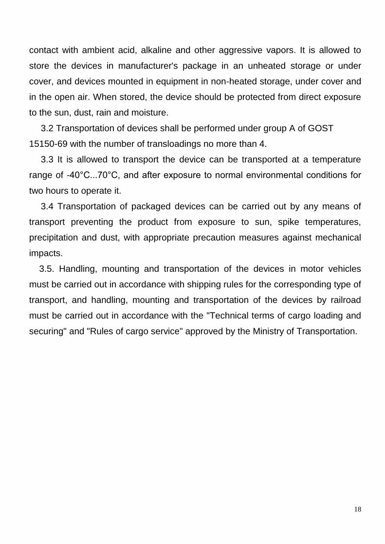
3. Handling and storage.
3.1 Devices in the original manufacturer package, as well as devices mounted
in equipment should be stored indoors at a temperature of -30°C...+60°C without
18
contact with ambient acid, alkaline and other aggressive vapors. It is allowed to
store the devices in manufacturer's package in an unheated storage or under
cover, and devices mounted in equipment in non-heated storage, under cover and
in the open air. When stored, the device should be protected from direct exposure
to the sun, dust, rain and moisture.
3.2 Transportation of devices shall be performed under group A of GOST
15150-69 with the number of transloadings no more than 4.
3.3 It is allowed to transport the device can be transported at a temperature
range of -40°C...70°C, and after exposure to normal environmental conditions for
two hours to operate it.
3.4 Transportation of packaged devices can be carried out by any means of
transport preventing the product from exposure to sun, spike temperatures,
precipitation and dust, with appropriate precaution measures against mechanical
impacts.
3.5. Handling, mounting and transportation of the devices in motor vehicles
must be carried out in accordance with shipping rules for the corresponding type of
transport, and handling, mounting and transportation of the devices by railroad
must be carried out in accordance with the "Technical terms of cargo loading and
securing" and "Rules of cargo service" approved by the Ministry of Transportation.
19
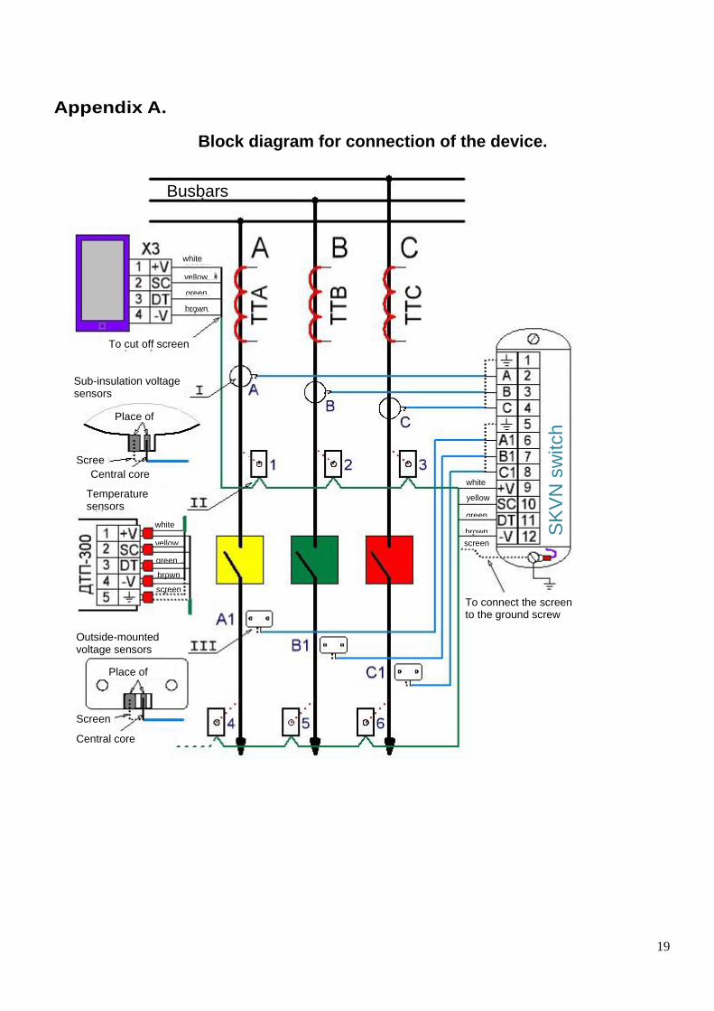
Appendix A.
Block diagram for connection of the device.
SK
VN
sw
itch
Busbars
To cut off screen
Sub-insulation voltage sensors
Place of soldering
Screen Central core
Temperature sensors
Screen
Place of soldering
Central core
Outside-mounted voltage sensors
To connect the screen to the ground screw
white
yellow
green
brown
screen
screen
brown
green
yellow
white
white
yellow
green
brown
20
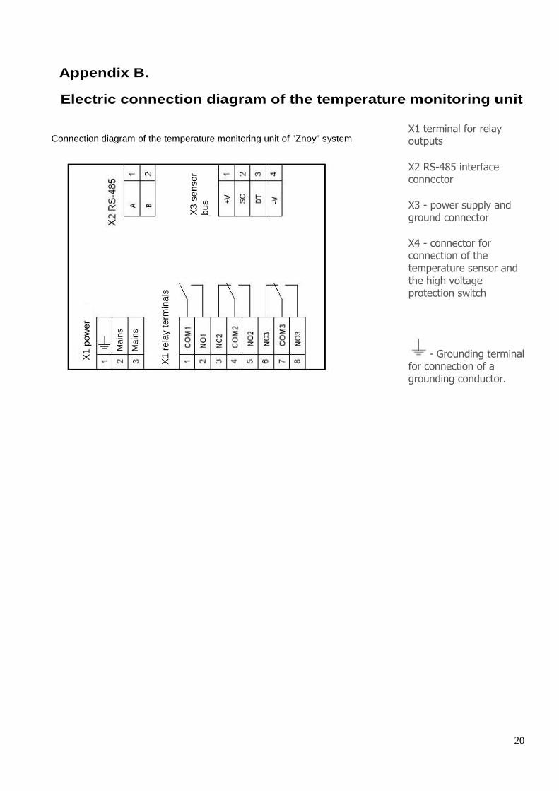
Appendix B.
Electric connection diagram of the temperature monitoring unit
X1 terminal for relay outputs
X2 RS-485 interface connector
X3 - power supply and ground connector
X4 - connector for connection of the temperature sensor and the high voltage protection switch
- Grounding terminal for connection of a grounding conductor.
X3 s
ensor
bus
X1 r
ela
y term
inals
X1 p
ow
er
supply
Connection diagram of the temperature monitoring unit of "Znoy" system
Ma
ins
Ma
ins

21
Appendix C.
Product order code
Znoy-(SKVN)-(DDT)-(LLm)
Name ________________________ High voltage control system (SKVN) _____________ SKVN - yes Whitespace - no Number of temperature sensors ________________________ Whitespace - without sensors 01T - 1 sensor... 12T - 12 sensors Length of the communication cable __________________________ Whitespace - without cable 10 m - 10 meters
Any additional technical information must be specified in the order form when ordering the device.

22
Appendix D.
Overall and installation dimensions of the unit.
Power supply check
Sensor communication check
Temperature threshold 1
Temperature threshold 2
ZNOY
Temperature measurement unit
Serial no.
Ma
ins
Ma
ins
Hou
sin
g
23
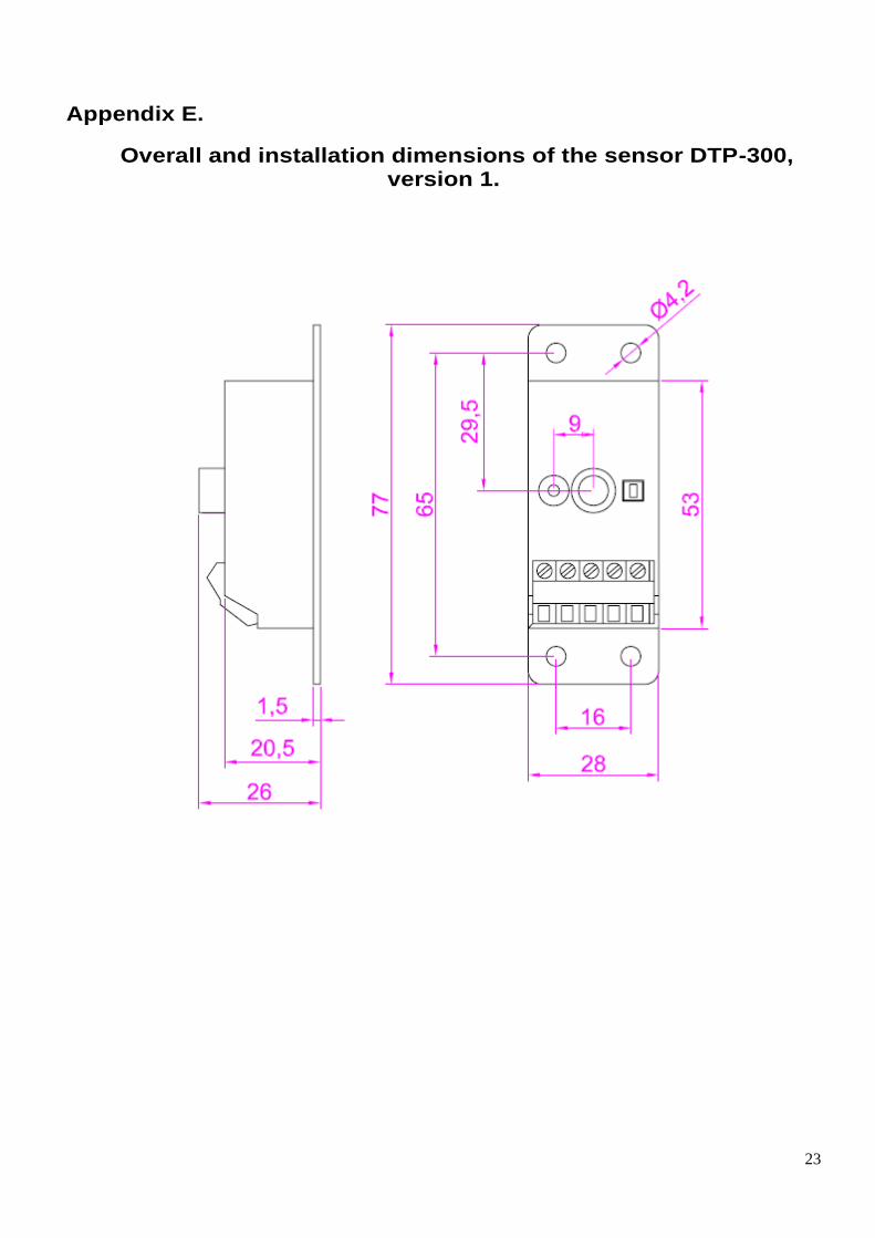
Appendix E.
Overall and installation dimensions of the sensor DTP-300, version 1.

24
Appendix F.
Overall and installation dimensions of the sensor DTP-300, version 2.
25
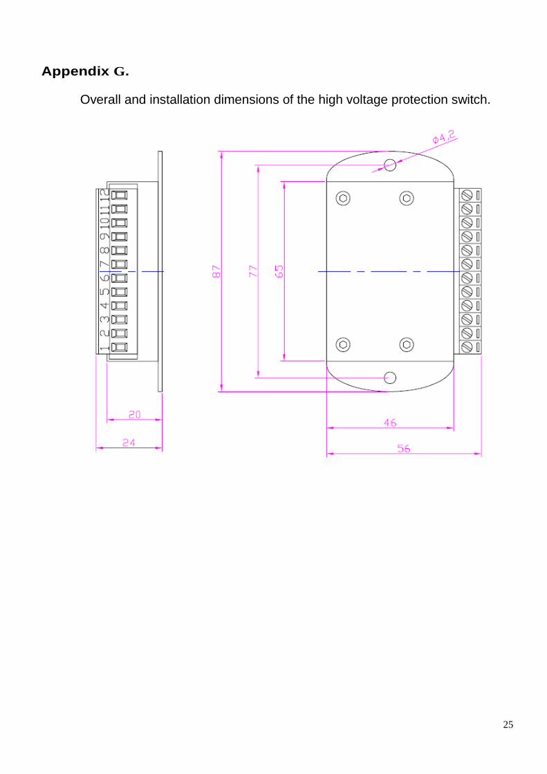
Appendix G.
Overall and installation dimensions of the high voltage protection switch.

26
Appendix H.
Overall and installation dimensions of the outside-mounted voltage sensor.
Internally threaded insert M4
Soldered joint
holes

27
Appendix I.
Dimensions of the sub-insulation voltage sensor.
Through hole
Dimensions of the 10kV sensor
Soldered joint

28
Through hole
Soldered joint
Dimensions of the 20kV sensor