Airplane Factory SLING 2 - GAPgap.aero/pdf/sling/Sling-2-POH-2.3-RSA-operating_handbook.pdf ·...
192
Transcript of Airplane Factory SLING 2 - GAPgap.aero/pdf/sling/Sling-2-POH-2.3-RSA-operating_handbook.pdf ·...


Airplane Factory SLING 2 Pilot Operating Handbook
Page | ii DC-POH-002-X-B-3 Revision : 2.3
Airplane model : Airplane Factory Sling 2 Manufacturer : The Airplane Factory (Pty) Ltd Airplane Serial Number : ………………………………. Date of Construction : ……………………………….. Registration : ………………………………………. Airworthiness Category : CS-VLA (Very Light Aircraft) Issue Date of POH : 2014/11/10
PLEASE ADVISE THE AIRPLANE FACTORY ON CHANGE OF OWNERSHIP OF THE AIRCRAFT
This airplane must be operated in compliance with information and limitations contained herein. This pilot operating handbook must be
available on board of the airplane at all times.

Airplane Factory SLING 2 Pilot Operating Handbook
Page | iii DC-POH-002-X-B-3 Revision : 2.3
NOTICE THIS MANUAL IS WRITTEN FOR THE STANDARD 912 ULS POWERED SLING 2, AS MANUFACTURED ON PREMISES BY THE AIRPLANE FACTORY (PTY) LTD. DIFFERENCES APPLICABLE TO THE STANDARD 914 UL AND 912 iS POWERED SLING 2 AIRCRAFT, AS MANUFACTURED ON PREMISES BY THE AIRPLANE FACTORY (PTY) LTD, ARE INCLUDED IN APPLICABLE SUPPLEMENTS IN SECTION 9 OF THIS HANDBOOK. AIRCRAFT WHICH DIFFER FROM THE PRODUCTION STANDARD, IN WHATEVER WAY, ARE NOT ADDRESSED IN THIS MANUAL, EXCEPT TO THE EXTENT SAID AIRCRAFT CORRESPOND WITH THE PRODUCTION STANDARD.
NOTICE
THIS EDITION OF THIS MANUAL IS APPLICABLE TO AIRCRAFT REGISTERED IN THE REPUBLIC OF SOUTH AFRICA. DEFINITIONS ARE ACCORDINGLY CONSISTENT WITH RSA REGULATIONS ONLY.


Airplane Factory SLING 2 Pilot Operating Handbook
Page | v DC-POH-002-X-B-3 Revision : 2.3
LIST OF EFFECTIVE PAGES
Page Page Status Latest Revision Page Page Status Latest revision
i Revised 2.3 1-12 Revised 2.3
ii Revised 2.3 1-13 Revised 2.3
iii Revised 2.3 1-14 Revised 2.3
iv Revised 2.3 1-15 Revised 2.3
v Revised 2.3 1-16 Revised 2.3
vi Revised 2.3 1-17 Revised 2.3
vii Revised 2.3 1-18 Revised 2.3
viii Revised 2.3 1-19 Revised 2.3
ix Revised 2.3 2-1/2-2 Revised 2.3
x Revised 2.3 2-3 Revised 2.3
1-1/1-2 Revised 2.3 2-4 Revised 2.3
1-3 Revised 2.3 2-5 Revised 2.3
1-4 Revised 2.3 2-6 Revised 2.3
1-5 Revised 2.3 2-7 Revised 2.3
1-6 Revised 2.3 2-8 Revised 2.3
1-7 Revised 2.3 2-9 Revised 2.3
1-8 Revised 2.3 2-10 Revised 2.3
1-9 Revised 2.3 2-11 Revised 2.3
1-10 Revised 2.3 2-12 Revised 2.3
1-11 Revised 2.3 2-13 Revised 2.3

Airplane Factory SLING 2 Pilot Operating Handbook
Page | vi DC-POH-002-X-B-3 Revision : 2.3
Page Page Status Latest Revision Page Page Status Latest Revision
2-14 Revised 2.3 3-19 Revised 2.3
2-15 Revised 2.3 3-20 Revised 2.3
2-16 Revised 2.3 3-21 Revised 2.3
2-17 Revised 2.3 4-1/4-2 Revised 2.3
3-1/3-2 Revised 2.3 4-3 Revised 2.3
3-3 Revised 2.3 4-4 Revised 2.3
3-4 Revised 2.3 4-5 Revised 2.3
3-5 Revised 2.3 4-6 Revised 2.3
3-6 Revised 2.3 4-7 Revised 2.3
3-7 Revised 2.3 4-8 Revised 2.3
3-8 Revised 2.3 4-9 Revised 2.3
3-9 Revised 2.3 4-10 Revised 2.3
3-10 Revised 2.3 4-11 Revised 2.3
3-11 Revised 2.3 4-12 Revised 2.3
3-12 Revised 2.3 4-13 Revised 2.3
3-13 Revised 2.3 4-14 Revised 2.3
3-14 Revised 2.3 4-15 Revised 2.3
3-15 Revised 2.3 4-16 Revised 2.3
3-16 Revised 2.3 4-17 Revised 2.3
3-17 Revised 2.3 4-18 Revised 2.3
3-18 Revised 2.3 4-19 Revised 2.3

Airplane Factory SLING 2 Pilot Operating Handbook
Page | vii DC-POH-002-X-B-3 Revision : 2.3
4-20 Revised 2.3 7-7 Revised 2.3
4-21 Revised 2.3 7-8 Revised 2.3
4-22 Revised 2.3 7-9 Revised 2.3
5-1/5-2 Revised 2.3 7-10 Revised 2.3
5-3 Revised 2.3 7-11 Revised 2.3
5-4 Revised 2.3 7-12 Revised 2.3
5-5 Revised 2.3 7-13 Revised 2.3
5-6 Revised 2.3 7-14 Revised 2.3
5-7 Revised 2.3 7-15 Revised 2.3
6-1/6-2 Revised 2.3 7-16 Revised 2.3
6-3 Revised 2.3 7-17 Revised 2.3
6-4 Revised 2.3 7-18 Revised 2.3
6-5 Revised 2.3 7-19 Revised 2.3
6-6 Revised 2.3 7-20 Revised 2.3
6-7 Revised 2.3 7-21 Revised 2.3
6-8 Revised 2.3 7-22 Revised 2.3
6-9 Revised 2.3 7-23 Revised 2.3
7-1/7-2 Revised 2.3 7-24 Revised 2.3
7-3 Revised 2.3 7-25 Revised 2.3
7-4 Revised 2.3 7-26 Revised 2.3
7-5 Revised 2.3 7-27 Revised 2.3
7-6 Revised 2.3 7-28 Revised 2.3
Airplane Factory SLING 2 Pilot Operating Handbook
Page | viii DC-POH-002-X-B-3 Revision : 2.3
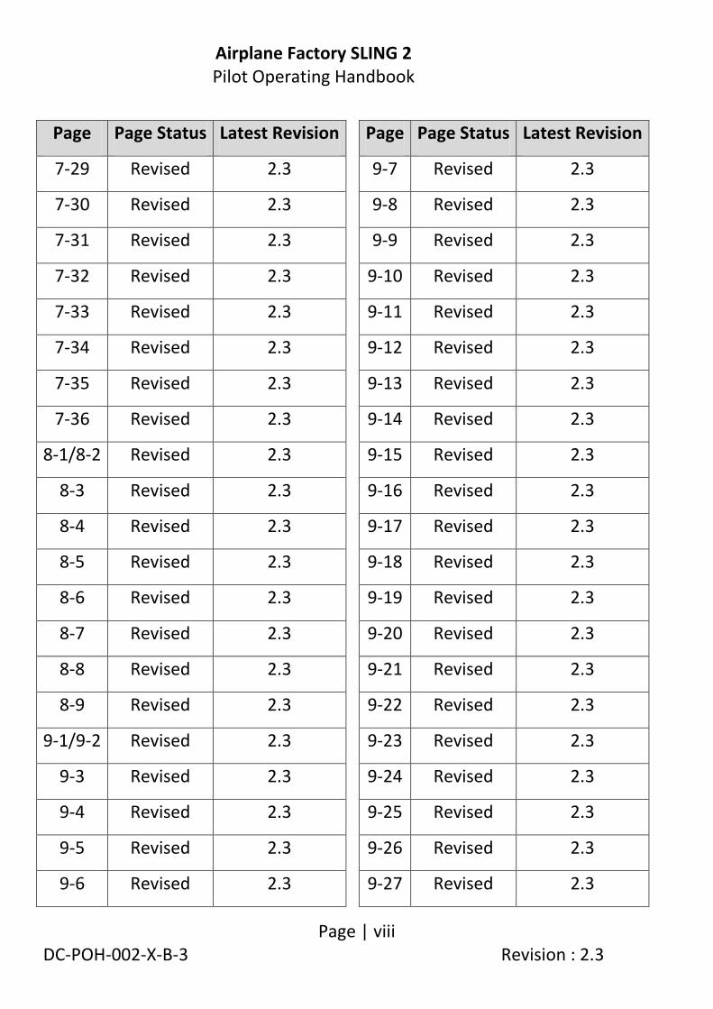
Page Page Status Latest Revision Page Page Status Latest Revision
7-29 Revised 2.3 9-7 Revised 2.3
7-30 Revised 2.3 9-8 Revised 2.3
7-31 Revised 2.3 9-9 Revised 2.3
7-32 Revised 2.3 9-10 Revised 2.3
7-33 Revised 2.3 9-11 Revised 2.3
7-34 Revised 2.3 9-12 Revised 2.3
7-35 Revised 2.3 9-13 Revised 2.3
7-36 Revised 2.3 9-14 Revised 2.3
8-1/8-2 Revised 2.3 9-15 Revised 2.3
8-3 Revised 2.3 9-16 Revised 2.3
8-4 Revised 2.3 9-17 Revised 2.3
8-5 Revised 2.3 9-18 Revised 2.3
8-6 Revised 2.3 9-19 Revised 2.3
8-7 Revised 2.3 9-20 Revised 2.3
8-8 Revised 2.3 9-21 Revised 2.3
8-9 Revised 2.3 9-22 Revised 2.3
9-1/9-2 Revised 2.3 9-23 Revised 2.3
9-3 Revised 2.3 9-24 Revised 2.3
9-4 Revised 2.3 9-25 Revised 2.3
9-5 Revised 2.3 9-26 Revised 2.3
9-6 Revised 2.3 9-27 Revised 2.3

Airplane Factory SLING 2 Pilot Operating Handbook
Page | ix DC-POH-002-X-B-3 Revision : 2.3
9-28 Revised 2.3 9-51 Revised 2.3
9-29 Revised 2.3
9-30 Revised 2.3
9-31 Revised 2.3
9-32 Revised 2.3
9-33 Revised 2.3
9-34 Revised 2.3
9-35 Revised 2.3
9-36 Revised 2.3
9-37 Revised 2.3
9-38 Revised 2.3
9-39 Revised 2.3
9-40 Revised 2.3
9-41 Revised 2.3
9-42 Revised 2.3
9-43 Revised 2.3
9-44 Revised 2.3
9-45 Revised 2.3
9-46 Revised 2.3
9-47 Revised 2.3
9-48 Revised 2.3
9-49 Revised 2.3
Airplane Factory SLING 2 Pilot Operating Handbook
Page | x DC-POH-002-X-B-3 Revision : 2.3
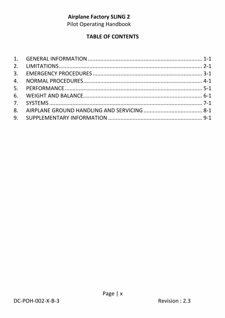
TABLE OF CONTENTS 1. GENERAL INFORMATION .......................................................................... 1-1
2. LIMITATIONS ............................................................................................. 2-1
3. EMERGENCY PROCEDURES ....................................................................... 3-1
4. NORMAL PROCEDURES ............................................................................. 4-1
5. PERFORMANCE ......................................................................................... 5-1
6. WEIGHT AND BALANCE ............................................................................. 6-1
7. SYSTEMS ................................................................................................... 7-1
8. AIRPLANE GROUND HANDLING AND SERVICING ...................................... 8-1
9. SUPPLEMENTARY INFORMATION ............................................................. 9-1

Airplane Factory SLING 2 Pilot Operating Handbook
Page | 1-1/1-2 DC-POH-002-X-B-3 Revision : 2.3
1. GENERAL INFORMATION
1.1 Introduction to airplane............................................................................ 1-3
1.2 Warnings, cautions and notes .................................................................. 1-4
1.3 Aircraft 3-view drawing ............................................................................ 1-5
1.4 Data for Sling 2 aircraft and systems ........................................................ 1-7
1.5 Terminology, symbols and conversion factors ........................................ 1-13
1.6 Supporting documents ........................................................................... 1-19

Airplane Factory SLING 2 Pilot Operating Handbook
Page | 1-3 DC-POH-002-X-B-3 Revision : 2.3
1.1 Introduction to airplane
The Airplane Factory Sling 2 is a two seat (sid-by-side), single engine, tricycle undercarriage aluminium aircraft with a conventional low wing design The aircraft is based upon the EASA CS-VLA (Certification Standard Very Light Aircraft) standard, having a maximum all up weight of 700 kg. With only minor modifications to the aircraft and the application of a revised Pilot Operating Handbook the Sling 2 may be made to comply with the requirements of the FAA Light Sport Aircraft (LSA) category according to ASTM Standards F2245, F2279 and F2295. In this configuration the Sling is known as the Sling LSA. The Sling 2 is intended chiefly for recreational and cross-country flying. It is not intended for aerobatic operation. It is considered to be suitable for use as a trainer. This Pilot Operating Handbook has been prepared to provide pilots with information for the safe and efficient operation of the Sling 2.

Airplane Factory SLING 2 Pilot Operating Handbook
Page | 1-4 DC-POH-002-X-B-3 Revision : 2.3
1.2 Warnings, cautions and notes The following definitions apply to warnings, cautions and notes in the Pilot Operating Handbook. Means that non-observation of the corresponding procedure leads to an immediate or important degradation of flight safety. Means that non-observation of the corresponding procedure leads to a minor or possible long term degradation of flight safety. Draws attention to any special item not directly related to safety but which is important or unusual.
WARNING
CAUTION
NOTE

Airplane Factory SLING 2 Pilot Operating Handbook
Page | 1-5 DC-POH-002-X-B-3 Revision : 2.3
1.3 Aircraft 3-view drawing
DIMENSIONS IN THIS DRAWING ARE IN MILLIMETRES.

Airplane Factory SLING 2 Pilot Operating Handbook
Page | 1-6 DC-POH-002-X-B-3 Revision : 2.3
DIMENSIONS IN THIS DRAWING ARE IN MILLIMETRES.

Airplane Factory SLING 2 Pilot Operating Handbook
Page | 1-7 DC-POH-002-X-B-3 Revision : 2.3
1.4 Data for Sling 2 aircraft and systems WING
Wing span: 9.165 m 30 ft. Mean Aerodynamic Chord: 1.339 m 52.7 inch. Wing surface area: 11.845 m2 131.75 sq ft. Wing loading: 59.10 kgm-2 11.7 lbs /sq ft. Aspect ratio: 7.04. Taper ratio: 1.375. Dihedral: 5o FUSELAGE Fuselage length: 5.77 m 19 ft. Overall length: 6.675 m 21ft 11 inch. Overall width: 1.18 m 45 inch. Overall height: 2. 45m 98 inch. EMPENNAGE Horizontal stabilizer span: 2.825 m 9 ft 3 inch. Horizontal stabilizer surface area: 0.96 m2 10 ft2 Elevator surface area: 1.02 m2 11 ft2 Horizontal stabilizer angle of incidence -4o Vertical stabilizer span: 1.47 m 16 ft Vertical stabilizer surface area: 0.53 m2 6 ft2 Rudder surface area: 0.59 m2 6 ft2 LANDING GEAR Wheel track: 1.95 m 6ft 5 inch. Wheel base: 1.41m 4ft 6 inch. Brakes: Hydraulic. Main gear tyres: 15x6.00-6, 6-ply
(2.2 bar (31.908 psi) pressure).

Airplane Factory SLING 2 Pilot Operating Handbook
Page | 1-8 DC-POH-002-X-B-3 Revision : 2.3
Nose gear tyres: 5.00-5, 6-ply (1.8 bar (26.107 psi) pressure).
CONTROL SURFACE TRAVEL LIMITS
Ailerons: 24o up and down (±2°). Elevator: 30o up and 20o down (±2°). Trim tab: 5o up and 32o down (±5°). Rudder: 25o left and right (±2°). Flaps: 0o to 30o down(±3°).

Airplane Factory SLING 2 Pilot Operating Handbook
Page | 1-9 DC-POH-002-X-B-3 Revision : 2.3
ENGINE Manufacturer: Bombardier-Rotax GmbH. Model: 912 ULS. Type: 4 Cylinder horizontally opposed with overall
displacement 1 352 cc, mixed cooling (water-cooled heads and air-cooled cylinders), twin carburetors, integrated reduction gearbox with torque damper
Maximum power: 73.5 kW (98.5hp) at 5 800 rpm (max 5 minutes). 69 kW (92.5hp) at 5 500 rpm (continuous). For Sling 2 aircraft fitted with the 912 iS or 914 UL engine refer to the applicable supplement at the end of this manual. PROPELLER
Manufacturer: Warp drive. No of blades: 3. Diameter: 1.83 m (72 “). Type: Composite. For aircraft fitted with the Airmaster 332 constant speed propeller refer to the applicable supplement at the end of this manual.

Airplane Factory SLING 2 Pilot Operating Handbook
Page | 1-10 DC-POH-002-X-B-3 Revision : 2.3
FUEL Fuel grade: Minimum RON 95 / minimum AKI 91.
MOGAS: EN 228 Super, EN 228 Super plus, ASTMD4814.
Leaded AVGAS: AVGAS 100LL (ASTM D910). Unleaded AVGAS: UL91 (ASTM D7547).
(Refer to latest revision of engine operator / maintenance manual and latest revision of service instruction SI-912-016. For aircraft fitted with the 912 iS or 914 UL engine refer to the applicable supplement at the end of this manual).
Fuel tanks: 2 x Wing tanks, one tank integrated within each
wing leading edge, each tank equipped with finger strainers (in pick up line) and drain fittings.
Capacity of each tank: 75 litres (19.81 US gallons). Total capacity: 150 litres (39.63 US gallons). Total usable fuel: 146 litres (38.57 US gallons).

Airplane Factory SLING 2 Pilot Operating Handbook
Page | 1-11 DC-POH-002-X-B-3 Revision : 2.3
OIL SYSTEM Oil system type: Forced, with external oil reservoir. Oil: Automotive grade API “SF” or “SG” type oil
preferably synthetic or semi-synthetic. When operating on unleaded fuels or MOGAS fully synthetic oil is recommended.
(Refer to latest revision of engine operator / maintenance manual and latest revision of service instruction SI-912-016. For aircraft fitted with the 912 iS or 914 UL engine refer to the applicable supplement at the end of this manual).
Capacity: 3.5 litres / 7.4 pints (approximately). COOLING Cooling system: Mixed: air and liquid pressurized closed circuit
system. Coolant: 1. Water-free propylene glycol based coolant
concentrate (this is not allowed for 912 iS engine).
2. Ethylene glycol based coolant mixed 1:1 with distilled water.
Note: Do not mix the above types of coolant. Capacity: 2.5 litres / 5.28 pints (approximately).

Airplane Factory SLING 2 Pilot Operating Handbook
Page | 1-12 DC-POH-002-X-B-3 Revision : 2.3
MAXIMUM WEIGHTS Maximum take-off weight: 700 kg 1 543.23 lb. Maximum landing weight: 700 kg 1 543.23 lb. Maximum baggage weight: 35 kg 77 lb. Front luggage compartment maximum 35 kg (77 lb). Rear luggage compartment maximum 25 kg (55 lb). STANDARD WEIGHTS Standard empty weight: 370 kg 814 lb. Maximum useful load: 330 kg 726 lb. SPECIFIC LOADINGS Wing loading: 59.07 kg.m-2 11.69 lb.ft-2 Power loading: 7.00 kg.hp-1 15.4 lb.hp-1

Airplane Factory SLING 2 Pilot Operating Handbook
Page | 1-13 DC-POH-002-X-B-3 Revision : 2.3
1.5 Terminology, symbols and conversion factors General terminology / acronyms
AC Alternating Current.
ALT Altimeter.
API American Petroleum Institute
ASI Airspeed Indicator.
ASTM American Society for Testing and Materials
AKI Anti Knock Index
AVGAS Aviation gasoline.
COM Communication (radio). CS-VLA Certification Standard Very Light Aircraft
EASA European Aviation Safety Agency
EFIS Electronic Flight Information System.
FAA Federal Aviation Authority.
GLS GPS Landing System.
GmbH Gesellschaft mit beschränkter Haftung (company with limited liability).
GPS Global Positioning System.
IFR Instrument Flying Rules.
LED Light Emitting Diode.
LSA Light Sport Aircraft
MOGAS Automobile (car) gasoline.
NGL Normal Ground Line.
NRV Non Return Valve.
POH Pilot Operating Handbook. PTT Push-To-Talk (button).
RON Research Octane Number
RSA Republic of South Africa
VFR Visual Flying Rules.
VMC Visual Meteorological Conditions.
VSI Vertical Speed Indicator.
Airplane Factory SLING 2 Pilot Operating Handbook
Page | 1-14 DC-POH-002-X-B-3 Revision : 2.3
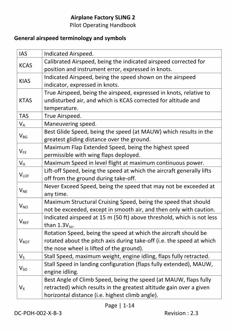
General airspeed terminology and symbols
IAS Indicated Airspeed.
KCAS Calibrated Airspeed, being the indicated airspeed corrected for position and instrument error, expressed in knots.
KIAS Indicated Airspeed, being the speed shown on the airspeed indicator, expressed in knots.
KTAS True Airspeed, being the airspeed, expressed in knots, relative to undisturbed air, and which is KCAS corrected for altitude and temperature.
TAS True Airspeed.
VA Maneuvering speed.
VBG Best Glide Speed, being the speed (at MAUW) which results in the greatest gliding distance over the ground.
VFE Maximum Flap Extended Speed, being the highest speed permissible with wing flaps deployed.
VH Maximum Speed in level flight at maximum continuous power.
VLOF Lift-off Speed, being the speed at which the aircraft generally lifts off from the ground during take-off.
VNE Never Exceed Speed, being the speed that may not be exceeded at any time.
VNO Maximum Structural Cruising Speed, being the speed that should not be exceeded, except in smooth air, and then only with caution.
VREF Indicated airspeed at 15 m (50 ft) above threshold, which is not less than 1.3Vso.
VROT Rotation Speed, being the speed at which the aircraft should be rotated about the pitch axis during take-off (i.e. the speed at which the nose wheel is lifted of the ground).
VS Stall Speed, maximum weight, engine idling, flaps fully retracted.
VSO Stall Speed in landing configuration (flaps fully extended), MAUW, engine idling.
VX Best Angle of Climb Speed, being the speed (at MAUW, flaps fully retracted) which results in the greatest altitude gain over a given horizontal distance (i.e. highest climb angle).

Airplane Factory SLING 2 Pilot Operating Handbook
Page | 1-15 DC-POH-002-X-B-3 Revision : 2.3
VY Best Rate of Climb Speed, being the speed (at MAUW, flaps fully retracted) which results in the greatest altitude gain over a given time period.
Meteorological terminology
ISA International Standard Atmosphere.
QNH The local pressure setting that if set on the subscale of an altimeter will cause the altimeter to indicate local altitude above mean sea level.
QFE The local airfield pressure setting that if set on the subscale of an altimeter will cause the altimeter to indicate local height above airfield.
Engine terminology
CHT Cylinder Head Temperature.
EGT Exhaust Gas Temperature.
OHV Overhead Valve.
RPM/ rpm
Revolutions per minute, being the number of revolutions per minute of the engine crank.
TCU Turbocharger Control Unit

Airplane Factory SLING 2 Pilot Operating Handbook
Page | 1-16 DC-POH-002-X-B-3 Revision : 2.3
Airplane performance and flight planning terminology
Crosswind component
The velocity of the crosswind component for which adequate control of the aircraft during takeoff and landing can be demonstrated.
g The acceleration / load factor.
Landing run The distance measured during landing from actual touchdown to the end of the landing run.
Landing distance
The distance measured during landing from clearance of a 15 m obstacle (in the air) to the end of the landing run.
Take-off distance
The take-off distance measured from the actual start of the take-off run to clearance of a 15 m (50 ft) obstacle (in the air).
Take-off run
The take-off distance measured from actual start of the take-off run to the wheel lift off point.
Usable fuel The fuel available for flight planning.
Airplane Factory SLING 2 Pilot Operating Handbook
Page | 1-17 DC-POH-002-X-B-3 Revision : 2.3
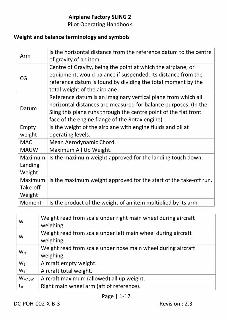
Weight and balance terminology and symbols
Arm Is the horizontal distance from the reference datum to the centre of gravity of an item.
CG
Centre of Gravity, being the point at which the airplane, or equipment, would balance if suspended. Its distance from the reference datum is found by dividing the total moment by the total weight of the airplane.
Datum
Reference datum is an imaginary vertical plane from which all horizontal distances are measured for balance purposes. (In the Sling this plane runs through the centre point of the flat front face of the engine flange of the Rotax engine).
Empty weight
Is the weight of the airplane with engine fluids and oil at operating levels.
MAC Mean Aerodynamic Chord.
MAUW Maximum All Up Weight.
Maximum Landing Weight
Is the maximum weight approved for the landing touch down.
Maximum Take-off Weight
Is the maximum weight approved for the start of the take-off run.
Moment Is the product of the weight of an item multiplied by its arm
WR Weight read from scale under right main wheel during aircraft weighing.
WL Weight read from scale under left main wheel during aircraft weighing.
WN Weight read from scale under nose main wheel during aircraft weighing.
WE Aircraft empty weight. WT Aircraft total weight. WMAUW Aircraft maximum (allowed) all up weight. LR Right main wheel arm (aft of reference).

Airplane Factory SLING 2 Pilot Operating Handbook
Page | 1-18 DC-POH-002-X-B-3 Revision : 2.3
LL Left main wheel arm (aft of reference). LN Nose wheel arm (aft of reference). MT Total moment arm.
Useful conversion factors
1 pound = 0.4536 kilogram 1 pound per square inch = 6.895 kilopascal 1 inch = 25.4 millimetres 1 foot = 0.3048 metre 1 statute mile = 1.609 kilometres 1 nautical mile = 1.852 kilometres 1 millibar = 1 hectopascal 1 millibar = 0.1 kilopascal 1 imperial gallon = 4.546 litres 1 US gallon = 3.785 litres 1 US quart = 0.946 litre 1 cubic foot = 28.317 litres degrees fahrenheit = [1.8 x degrees celsius] + 32 degrees celcius = (degrees fahrenheit - 32) x (5/9)

Airplane Factory SLING 2 Pilot Operating Handbook
Page | 2-19 DC-POH-002-X-B-3 Revision : 2.3
1.6 Supporting documents
The following documents are regarded as supporting documents to this Pilot Operating Handbook:
1. For aircraft fitted with 914 UL engines: latest revision / edition of
the Operators Manual For Rotax® Engine Type 914 Series, Ref No.: OM-914.
2. For aircraft fitted with 912 ULS engines: latest revision / edition of
the Operators Manual For Rotax® Engine Type 912 Series, Ref No.: OM-912.
3. For aircraft fitted with 912 iS engines: latest revision / edition of
the Operators Manual For Rotax® Engine Type 912 i Series, Ref No.: OM-912 i.
4. For aircraft fitted with an Airmaster constant speed propeller:
latest revision / edition of the Airmaster AP3 series And AP4 Series Constant Speed Propeller Operators Manual.
5. Latest revision / edition of Rotax service instruction SI-914-019,
SI-912-016 or SI-912i-001, as applicable (to type of engine fitted). 6. MGL EFIS operator manual. 7. Operator manuals for COM radio and transponder (if fitted)
equipment fitted to the aircraft.
Reference should be made to these documents for operational guidelines and instructions. These should be incorporated into the normal and emergency procedures for the aircraft as applicable.
.

Airplane Factory SLING 2 Pilot Operating Handbook
Page | 2-1/2-2 DC-POH-002-X-B-3 Revision : 2.3
2. LIMITATIONS
2.1 Introduction .............................................................................................. 2-3
2.2 Airspeed limitations .................................................................................. 2-3
2.3 Airspeed indicator markings ..................................................................... 2-4
2.4 Stall speed adjustment for turning flight and load factor ......................... 2-5
2.5 Crosswind and wind limitation (demonstrated) ....................................... 2-6
2.6 Service ceiling ........................................................................................... 2-6
2.7 Load factors .............................................................................................. 2-6
2.8 Weights..................................................................................................... 2-6
2.9 Centre of gravity range ............................................................................. 2-7
2.10 Prohibited maneuvers .............................................................................. 2-8
2.11 Flight crew ................................................................................................ 2-9
2.12 Passengers ................................................................................................ 2-9
2.13 Kinds of operation .................................................................................. 2-10
2.14 Engine operating limits ........................................................................... 2-11
2.15 Other limitations..................................................................................... 2-14
2.17 Limitation placards ................................................................................. 2-15

Airplane Factory SLING 2 Pilot Operating Handbook
Page | 2-3 DC-POH-002-X-B-3 Revision : 2.3
2.1 Introduction
This section includes operating limitations, instrument markings and basic placards necessary for the safe operation of the Airplane Factory Sling 2, its engine, systems and equipment.
2.2 Airspeed limitations
SPEED KIAS REMARKS
VNE Never exceed speed
135 Never exceed this speed in any operation.
VNO
Maximum structural cruising speed
110 Never exceed this speed unless in smooth air, and then only with caution.
VA Maneuvering speed
91 Do not make full or abrupt control movements above this speed as this may cause stress in excess of limit load factor.
VFE
Maximum flap extended speed
85 Never exceed this speed unless the flaps are fully retracted.
VH Maximum speed in level flight
116 The aircraft will not exceed this speed at MAUW in level flight, at maximum continuous power.
VS Stall speed (at MAUW)
46
At maximum all up weight in the most forward CG configuration, with flaps fully retracted, engine idling, the aircraft will stall if flown slower than this speed.
VS0 Stall speed with flaps
42 With full flap, maximum all up weight, engine idling, the aircraft will stall if flown slower than this speed.
Airplane Factory SLING 2 Pilot Operating Handbook
Page | 2-4 DC-POH-002-X-B-3 Revision : 2.3
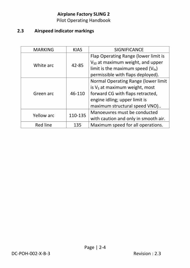
2.3 Airspeed indicator markings
MARKING KIAS SIGNIFICANCE
White arc 42-85
Flap Operating Range (lower limit is VS0 at maximum weight, and upper limit is the maximum speed (Vfe) permissible with flaps deployed).
Green arc 46-110
Normal Operating Range (lower limit is VS at maximum weight, most forward CG with flaps retracted, engine idling; upper limit is maximum structural speed VNO)..
Yellow arc 110-135 Manoeuvres must be conducted with caution and only in smooth air.
Red line 135 Maximum speed for all operations.

Airplane Factory SLING 2 Pilot Operating Handbook
Page | 2-5 DC-POH-002-X-B-3 Revision : 2.3
2.4 Stall speed adjustment for turning flight and load factor Stall speeds listed in Section 2 (this section) are listed for straight and level (non-turning) flight at load factor = 1 g and should be adjusted for turning flight or increased load factor:
M
ULT
IPLI
CA
TIO
N F
AC
TOR
0
.2
0
.4
0
.6
0
.8
1
.0
1
.2
1
.4
1
.6
1.8
0 10 20 30 40 50 60 70 80 90 BANK ANGLE (DEGREES)
This graph is only valid for level (i.e. non-descending) turning flight.
VT = V + ( V x MULTIPLICATION FACTOR )
V is straight and level stall speed (at load factor = 1 g).
VT is stall speed in turn (non-descending).
VST = V√
V is straight and level stall speed (at load factor = 1 g).
VST is stall speed due to increased load factor.
N is (positive) load factor.

Airplane Factory SLING 2 Pilot Operating Handbook
Page | 2-6 DC-POH-002-X-B-3 Revision : 2.3
2.5 Crosswind and wind limitation (demonstrated) Maximum demonstrated cross wind component for take-off and landing 15 kts.
2.6 Service ceiling Service ceiling 12 000 ft.
2.7 Load factors Maximum positive limit load factor + 4 g. Maximum negative limit load factor - 2 g. Maximum positive load factor with flaps 2 g.
Maximum negative load factor with flaps -1 g.
2.8 Weights Maximum take-off weight 700 kg (1 543.24 lb). Maximum landing weight 700 kg (1 543.24 lb). Maximum total baggage weight 35 kg (77 lb). Front luggage compartment maximum 35 kg (77 lb). Rear luggage compartment maximum 25 kg (55 lb).

Airplane Factory SLING 2 Pilot Operating Handbook
Page | 2-7 DC-POH-002-X-B-3 Revision : 2.3
2.9 Centre of gravity range Datum Centre of front face of engine flange
(without propeller extension). Reference (longitudinal leveling) Upper surface of canopy sliders on cockpit side skins, with canopy open. Reference (transverse leveling) Upper surface of centre spar cap under
pilot and passenger seats. Forward limit 1.635 m / 5.364 ft (20% MAC) aft of
datum. Rear limit 1.807 m / 5.931 ft (33% MAC) aft of
datum.
WARNING It is the pilot’s responsibility to ensure that the airplane is properly loaded. Refer to section 6
for information on weight and balance

Airplane Factory SLING 2 Pilot Operating Handbook
Page | 2-8 DC-POH-002-X-B-3 Revision : 2.3
2.10 Prohibited maneuvers The Sling is approved for normal maneuvers including the following:
Steep turns not exceeding 60° bank.
Lazy eights.
Chandelles.
Stalls (not including whip stalls).
WARNING Aerobatics and intentional spins are
prohibited
WARNING Limit load factor would be exceeded by
moving flight controls abruptly to their limits at a speed above VA (91 KIAS – maneuvering
speed)

Airplane Factory SLING 2 Pilot Operating Handbook
Page | 2-9 DC-POH-002-X-B-3 Revision : 2.3
2.11 Flight crew
Minimum crew for flight is one pilot seated on the left side.
2.12 Passengers
Only one passenger is allowed on board the aircraft (in addition to the pilot).

Airplane Factory SLING 2 Pilot Operating Handbook
Page | 2-10 DC-POH-002-X-B-3 Revision : 2.3
2.13 Kinds of operation
The Sling, in standard configuration, is approved only for day VFR operation with visual contact with terrain. Minimum equipment required is as follows-
Altimeter.
Airspeed indicator.
Compass.
Fuel gauges.
Oil pressure indicator.
Oil temperature indicator.
Cylinder head temperature indicator.
Outside air temperature indicator.
Tachometer.
Chronometer.
First aid kit (compliant with national legislation).
Fire extinguisher.
NOTE Additional equipment may be required to fulfill
national or specific requirements and may be fitted.
WARNING Notwithstanding that installed equipment may include GPS and
other advanced flight and navigational aids, such equipment may not be used as the sole information source for purposes of navigation or flight, save where specifically permitted by law. The airplane instrumentation is not certified and applicable
regulations should be complied with at all times.

Airplane Factory SLING 2 Pilot Operating Handbook
Page | 2-11 DC-POH-002-X-B-3 Revision : 2.3
2.14 Engine operating limits
Instruments reflecting engine parameters should in each case be marked / set to reflect the minimum and maximum figures.
Always refer to latest edition / revision of the Operators Manual for latest information regarding operating limitations.
ENGINE START AND OPERATION TEMPERATURE LIMITS (912 ULS)
Maximum 50 °C ( 122 °F) (ambient temperature)
Minimum -25 °C ( -13 °F) (oil temperature)
ENGINE LOAD FACTOR (ACCELERATION) LIMITS
Maximum 5 seconds at maximum -0.5 g.
For airplanes with the Rotax 912iS or 914UL engine installed, refer to the applicable supplement at the end of this manual.

Airplane Factory SLING 2 Pilot Operating Handbook
Page | 2-12 DC-POH-002-X-B-3 Revision : 2.3
ENGINE OPERATING AND SPEEDS LIMITS (912 ULS)
Engine Model: ROTAX 912 ULS
Engine Manufacturer: Bombardier-Rotax GMBH
Power
Maximum
take-off 73.5 kW (98.6 hp) at 5800 rpm, max. 5 min.
Maximum
continuous 69 kW (92.5 hp)at 5500 rpm
RPM
Maximum take-
off 5800 rpm, maximum 5 minutes
Maximum
continuous 5500 rpm
Idle 1 600 rpm (minimum)
Cylinder head
temperature
Minimum N/A
Maximum 135 °C (275 °F)
Normal 75 to 110 °C (167 to 230 °F)
Oil
temperature
Minimum 50 °C (122 °F)
Maximum 130 °C (266 °F)
Normal 90 to 110 °C (194 to 230 °F)
EGT Maximum 880 °C (1616 °F)
Coolant
temperature Maximum 120 °C (248 °F)
Oil pressure
Minimum 0.8 bar (12 psi) – below 3500 rpm
Maximum 7 bar (102 psi) – permissible for short period during cold
engine start
Normal 2 to 5 bar (29 to 73 psi) – above 3500 rpm
Airplane Factory SLING 2 Pilot Operating Handbook
Page | 2-13 DC-POH-002-X-B-3 Revision : 2.3
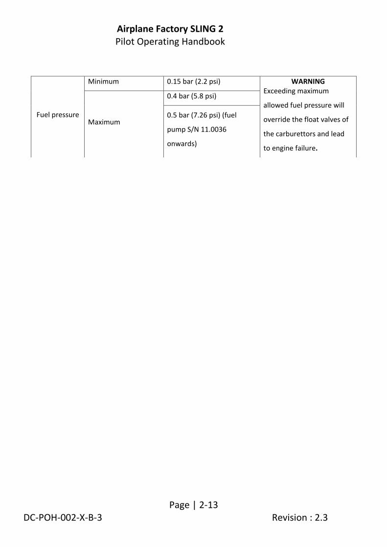
Fuel pressure
Minimum 0.15 bar (2.2 psi) WARNING Exceeding maximum
allowed fuel pressure will
override the float valves of
the carburettors and lead
to engine failure.
Maximum
0.4 bar (5.8 psi)
0.5 bar (7.26 psi) (fuel
pump S/N 11.0036
onwards)

Airplane Factory SLING 2 Pilot Operating Handbook
Page | 2-14 DC-POH-002-X-B-3 Revision : 2.3
2.15 Other limitations
No smoking is allowed on board of the airplane.
VFR flights only are permitted.
2.16 Flight in rain When flying in the rain no additional steps are required. Airplane qualities and performance are not substantially changed. However, VMC should be maintained.
WARNING IFR flights and intentional flights under icing
conditions are prohibited!
Airplane Factory SLING 2 Pilot Operating Handbook
Page | 2-15 DC-POH-002-X-B-3 Revision : 2.3
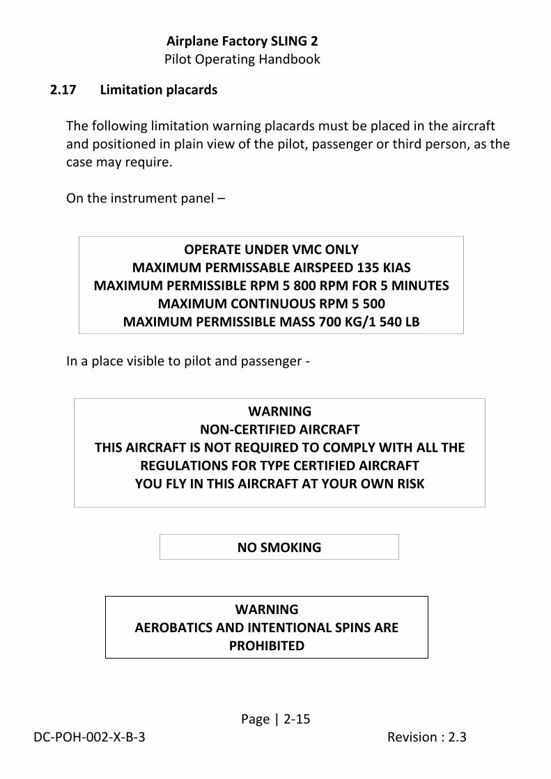
2.17 Limitation placards The following limitation warning placards must be placed in the aircraft and positioned in plain view of the pilot, passenger or third person, as the case may require. On the instrument panel – In a place visible to pilot and passenger -
OPERATE UNDER VMC ONLY MAXIMUM PERMISSABLE AIRSPEED 135 KIAS
MAXIMUM PERMISSIBLE RPM 5 800 RPM FOR 5 MINUTES MAXIMUM CONTINUOUS RPM 5 500
MAXIMUM PERMISSIBLE MASS 700 KG/1 540 LB
WARNING NON-CERTIFIED AIRCRAFT
THIS AIRCRAFT IS NOT REQUIRED TO COMPLY WITH ALL THE REGULATIONS FOR TYPE CERTIFIED AIRCRAFT
YOU FLY IN THIS AIRCRAFT AT YOUR OWN RISK
NO SMOKING
WARNING AEROBATICS AND INTENTIONAL SPINS ARE
PROHIBITED

Airplane Factory SLING 2 Pilot Operating Handbook
Page | 2-16 DC-POH-002-X-B-3 Revision : 2.3
On the baggage space separator channel - Adjacent to the fuel filler caps - On the inboard upper wing flap surface -
On a fireproof metal plate attached to the aircraft - Note: ### represents the information applicable to the aircraft.
AVGAS OR
MOGAS 75 LITRES
ZU-### CONSTRUCTOR – THE AIRPLANE FACTORY
MODEL – SLING 2 SERIAL NO – ###
ENGINE ROTAX 912 ULS – 100 HP MANUFACTURED - ###
NO STEP
MAX BAGGAGE WEIGHT – FRONT SECTION – 35 KG / 77 LB MAX BAGGAGE WEIGHT – REAR SECTION – 25 KG / 55 LB
MAX TOTAL BAGGAGE WEIGHT – 35 KG / 77 LB

Airplane Factory SLING 2 Pilot Operating Handbook
Page | 2-17 DC-POH-002-X-B-3 Revision : 2.3
The airplane must be placarded to show the identity of:
All fuses/circuit breakers.
Magneto / ignition switches.
All other switches.
Choke.
Starter.
Trim : Nose up and down.
Flaps : Up and Down.

Airplane Factory SLING 2 Pilot Operating Handbook
Page | 3-1/3-2 DC-POH-002-X-B-3 Revision : 2.3
3. EMERGENCY PROCEDURES
3.1 Introduction .............................................................................................. 3-3
3.2 Speeds for emergency operations ............................................................ 3-3
3.3 Engine related emergencies ..................................................................... 3-4
3.4 Smoke and fire .......................................................................................... 3-8
3.5 Emergency landings ................................................................................ 3-13
3.6 Recovery from unintentional spin .......................................................... 3-17
3.7 Other emergencies ................................................................................. 3-18
Airplane Factory SLING 2 Pilot Operating Handbook
Page | 3-3 DC-POH-002-X-B-3 Revision : 2.3
3.1 Introduction
This section provides checklists and amplified procedures for coping with various emergencies that may arise. Emergencies caused by aircraft or engine malfunction are extremely rare if proper pre-flight inspections and maintenance are practiced. However, should an emergency arise, the basic guidelines described in this section should be considered and applied as necessary to correct the problem. In case of emergency the pilot should remember the following priorities – 1 Keep control of and continue flying the aircraft. 2 Analyze the situation. 3 Apply applicable procedures. 4 Inform air traffic control of the situation if time and conditions
permit it.
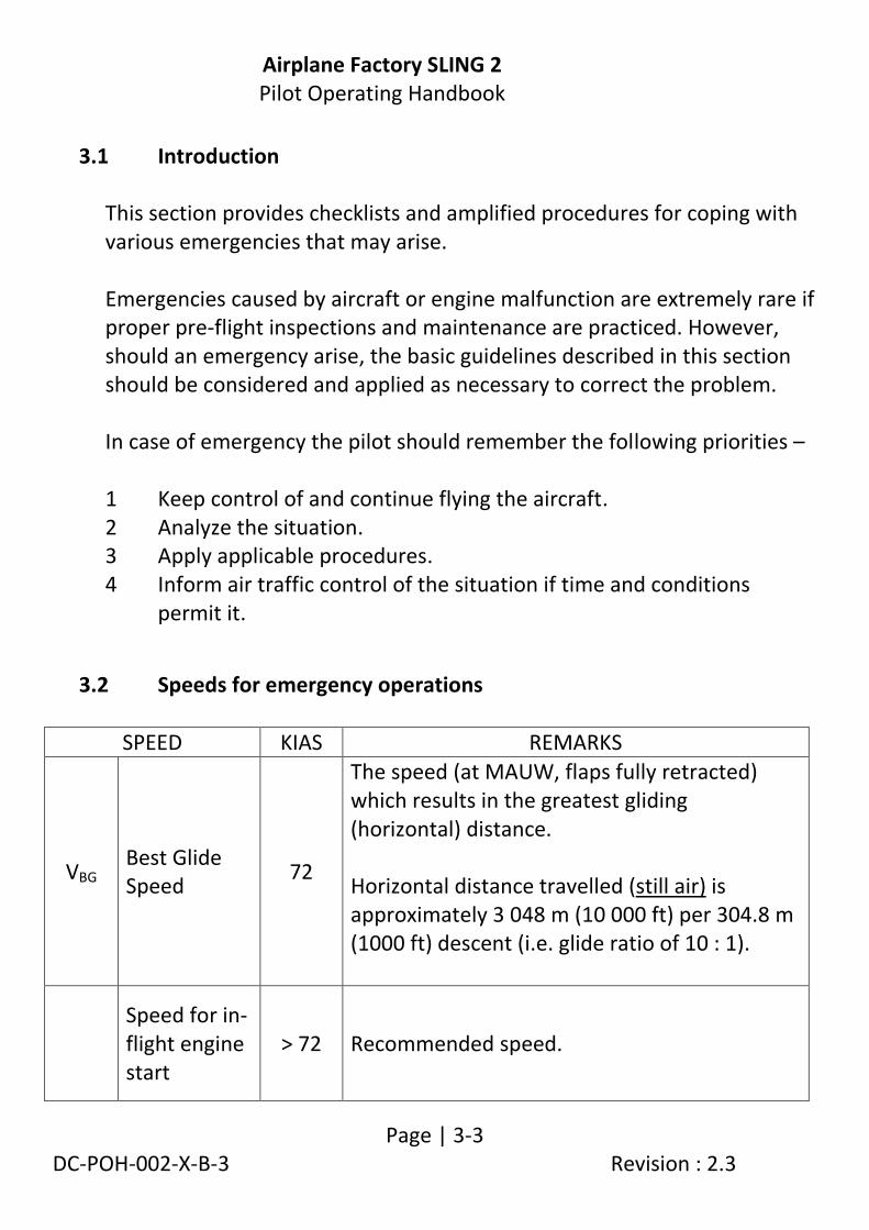
3.2 Speeds for emergency operations
SPEED KIAS REMARKS
VBG Best Glide Speed
72
The speed (at MAUW, flaps fully retracted) which results in the greatest gliding (horizontal) distance. Horizontal distance travelled (still air) is approximately 3 048 m (10 000 ft) per 304.8 m (1000 ft) descent (i.e. glide ratio of 10 : 1).
Speed for in-flight engine start
> 72 Recommended speed.

Airplane Factory SLING 2 Pilot Operating Handbook
Page | 3-4 DC-POH-002-X-B-3 Revision : 2.3
3.3 Engine related emergencies
3.3.1 Engine failure during take-off run 1. Throttle - idle. 2. Magnetos / ignition - off. 3. Brakes - apply as needed. With airplane under control – 4. Radio communication as required. 5. Master switch - off. 6. Fuel selector valve - off. 7. Auxiliary (electric) fuel pump - off (912 ULS). Electric fuel pumps (both) - off (914 UL / 912 iS). 8. Other electrical system switches - off.
3.3.2 Engine failure immediately after take-off 1. Speed / trim - best glide speed (72 KIAS). 2. Find a suitable place on the ground to land safely. The landing
should be planned straight ahead with only small changes in direction not exceeding 45 degrees to either side.
3. Flaps - as needed (plan to land as slowly as possible).
Before touch down 4. Magnetos / ignition - off. 5. Master - off. 6. Fuel selector valve - off. 7. Electric fuel pump - off (912 ULS). Electric fuel pumps (both) - off ( 914 UL / 912 iS).
WARNING Flaps and elevator trim cannot operate without power on the
main bus. Make final flap selection before turning
master switch off.

Airplane Factory SLING 2 Pilot Operating Handbook
Page | 3-5 DC-POH-002-X-B-3 Revision : 2.3
3.3.3 Engine irregularities in flight
3.3.3.1 Irregular engine rpm
1. Verify magneto switches - both on. 2. Verify throttle position. 3. Verify engine and fuel quantity indicators. 4. Electric fuel pump on (912 ULS). Auxiliary electric fuel pump on (914 UL / 912 iS). If engine continues to run irregularly 5. Change fuel selector valve to tank not in use (if not empty). If engine continues to run irregularly 6. Change to fullest tank. 7. Land as soon as possible.
3.3.3.2 Low fuel pressure (refer to engine limitations, Section 2 (912 ULS) or specific (914 UL / 912 iS) supplements .
1. Check fuel quantity indicator. 2. Switch electric fuel pump on (912 ULS). Switch auxiliary electric fuel pump on (914 UL / 912 iS). If fuel pressure remains low 3. Change fuel selector valve to tank not in use (if not empty). 4. Decrease throttle setting if viable to do so. If fuel pressure remains low 5. Land as soon as possible.

Airplane Factory SLING 2 Pilot Operating Handbook
Page | 3-6 DC-POH-002-X-B-3 Revision : 2.3
3.3.3.3 Low oil pressure (refer to engine limitations, Section 2 (912 ULS) or specific engine (914 UL / 912 iS) supplements at end of manual)
1. Check oil temperature. If oil temperature is high or increasing 2. Set throttle to a setting which gives an aircraft speed of 72 KIAS
(most efficient speed). If oil pressure remains low or temperature remains high or increasing 3. Land as soon as possible and remain vigilant for impending engine
failure.
3.3.4 In-flight engine restart 1. Electric fuel pump - on (912 ULS).
Electric fuel pumps (both) - on (914 UL / 912 iS). 2. Fuel selector - switch to unused / fullest tank. 3. Throttle - set to middle position. 4. Master switch - check on. 5. Magnetos / ignition - check both on. 6. Starter - engage. 7. Electric fuel pump - off (912 ULS) (after positive start). Auxiliary fuel pump - off (912 iS) (after positive start). If engine should fail to restart 8. Apply forced landing without engine power procedure, according
to 3.5.1.
Airplane Factory SLING 2 Pilot Operating Handbook
Page | 3-7 DC-POH-002-X-B-3 Revision : 2.3
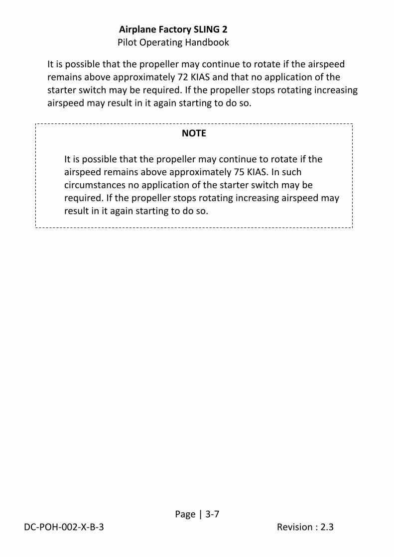
It is possible that the propeller may continue to rotate if the airspeed remains above approximately 72 KIAS and that no application of the starter switch may be required. If the propeller stops rotating increasing airspeed may result in it again starting to do so.
NOTE
It is possible that the propeller may continue to rotate if the airspeed remains above approximately 75 KIAS. In such circumstances no application of the starter switch may be required. If the propeller stops rotating increasing airspeed may result in it again starting to do so.

Airplane Factory SLING 2 Pilot Operating Handbook
Page | 3-8 DC-POH-002-X-B-3 Revision : 2.3
3.4 Smoke and fire
3.4.1 Engine fire on ground during start
1. Starter - release. 2. Fuel selector - close. 3. Electric fuel pumps (both) - off (914 UL / 912 iS). 4. Throttle - idle. 5. Magnetos / ignition - off. 6. Master switch - off. 7. Retrieve fire extinguisher if possible. 8. Exit the airplane. 9. Extinguish fire by fire extinguisher or call for a fire-brigade if you
cannot do it.
3.4.2 Engine fire on ground with engine running 1. Cabin heat - close. 2. Fuel selector - close. 3. Electric fuel pumps (both) - off (914 UL / 912 iS). 4. Throttle - idle. 5. Magnetos / ignition - off. 6. Master switch - off. 7. Retrieve fire extinguisher if possible. 8. Leave the airplane. 9. Extinguish fire by fire extinguisher or call for a fire-brigade if you
cannot do it.

Airplane Factory SLING 2 Pilot Operating Handbook
Page | 3-9 DC-POH-002-X-B-3 Revision : 2.3
3.4.3 Engine fire during take-off run 1. Throttle - idle. 2. Brakes - stop the aircraft. 3. Cabin heat - close. 4. Fuel selector - close. 5. Electric fuel pump(s) - off. 6. Magnetos / ignition - off. 7. Master switch - off. 8. Retrieve fire extinguisher if possible. 9. Exit the aircraft. 10. Extinguish the fire by fire extinguisher or call for fire services if
unable to do so.

Airplane Factory SLING 2 Pilot Operating Handbook
Page | 3-10 DC-POH-002-X-B-3 Revision : 2.3
3.4.4 Engine fire in flight 1. Cabin heat - close. 2. Fuel selector - close. 3. Throttle - full power. 4. Magnetos / ignition - switch off after the fuel in carburetors
is consumed and engine has shut down. 5. Electric fuel pumps (both) - off (914 UL / 912 iS). 6. Choose landing area - choose emergency landing area. 7. Emergency landing - perform according to 3.5.1. 8. Retrieve fire extinguisher if possible. 9. Leave the airplane. 10. Extinguish fire by fire extinguisher / call for fire-brigade if you
cannot do it.
NOTE Estimated time to empty carburetors
after fuel selector valve is closed is 30 seconds
WARNING Do not attempt to re-start
the engine!

Airplane Factory SLING 2 Pilot Operating Handbook
Page | 3-11 DC-POH-002-X-B-3 Revision : 2.3
3.4.5 Electrical fire in flight
An electrical fire is often characterized by white smoke and an acrid smell. 1. Auxiliary fuel pump - on (914 UL: see WARNING below). 2. Master switch - off (see NOTE below). 3. Cabin heat - close. 4. Use the fire extinguisher (if possible). 5. Ventilate cabin if required / applicable (open air vents on instrument
panel). 6. If fire is extinguished consider executing a precautionary landing /
land as soon as practical. If fire does not extinguish land immediately. NOTE:
If the location / source of the electrical fire can be determined and electrical power can be removed from that system / location by isolating / switching the system off, do so. This may alleviate the need to switch off the master switch.
For aircraft equipped with a 912 iS engine, refer to the applicable supplement at the end of this manual, with regard to the Master switch.
The EFIS and associated equipment (iBox, RDAC etc.) can still be powered (to provide engine monitoring) from the EFIS back-up battery circuit when the master switch is off, provided that the EFIS system is not the location / source of the electrical fire.
WARNING (914 UL) If the master switch is switched off without the auxiliary fuel pump
being ON both fuel pumps will be inoperative! This will lead to engine stoppage due to fuel starvation.

Airplane Factory SLING 2 Pilot Operating Handbook
Page | 3-12 DC-POH-002-X-B-3 Revision : 2.3
3.4.6 Cabin fire
If the fire is electrical in nature follow the procedure for electrical fires in flight (3.4.5). Alternatively: 1. Cabin heat - close. 2. Use the fire extinguisher (if possible). 3. Ventilate cabin if required / applicable (open air vents on instrument
panel). 4. If fire is extinguished consider executing a precautionary landing /
land as soon as practical. 5. If fire does not extinguish land immediately.

Airplane Factory SLING 2 Pilot Operating Handbook
Page | 3-13 DC-POH-002-X-B-3 Revision : 2.3
3.5 Emergency landings Emergency landings are generally carried out in the case of engine failure during which the engine cannot be re-started. Other reasons for an emergency landing may, however, arise.
3.5.1 Engine-off emergency landing
1. Speed - best glide speed (72 KIAS). 2. Trim - trim for best glide speed. 3. Landing location - locate most suitable landing location,
free of obstacles and preferably into wind.
4. Safety harness - tighten. 5. Engine restart - if time permits and if appropriate
attempt to identify reason for engine failure and attempt restart.
6. Propeller (if applicable) - if windmilling consider feathering to extend glide range (refer to emergency feather procedure below).
7. Flaps - extend as needed. 8. Communications - report your location to third parties if
possible. 9. Passenger - brief. Immediately before touchdown- 10. Fuel selector - shut off. 11. Auxiliary (electric) fuel pump - off (912 ULS). Electric fuel pumps (both) - off (914 UL / 912 iS). 12. Magnetos / ignition - off. 13. Master switch - off.
WARNING Flaps and elevator trim cannot operate without power on the main bus. Make final flap selection before turning master switch off.
Airplane Factory SLING 2 Pilot Operating Handbook
Page | 3-14 DC-POH-002-X-B-3 Revision : 2.3
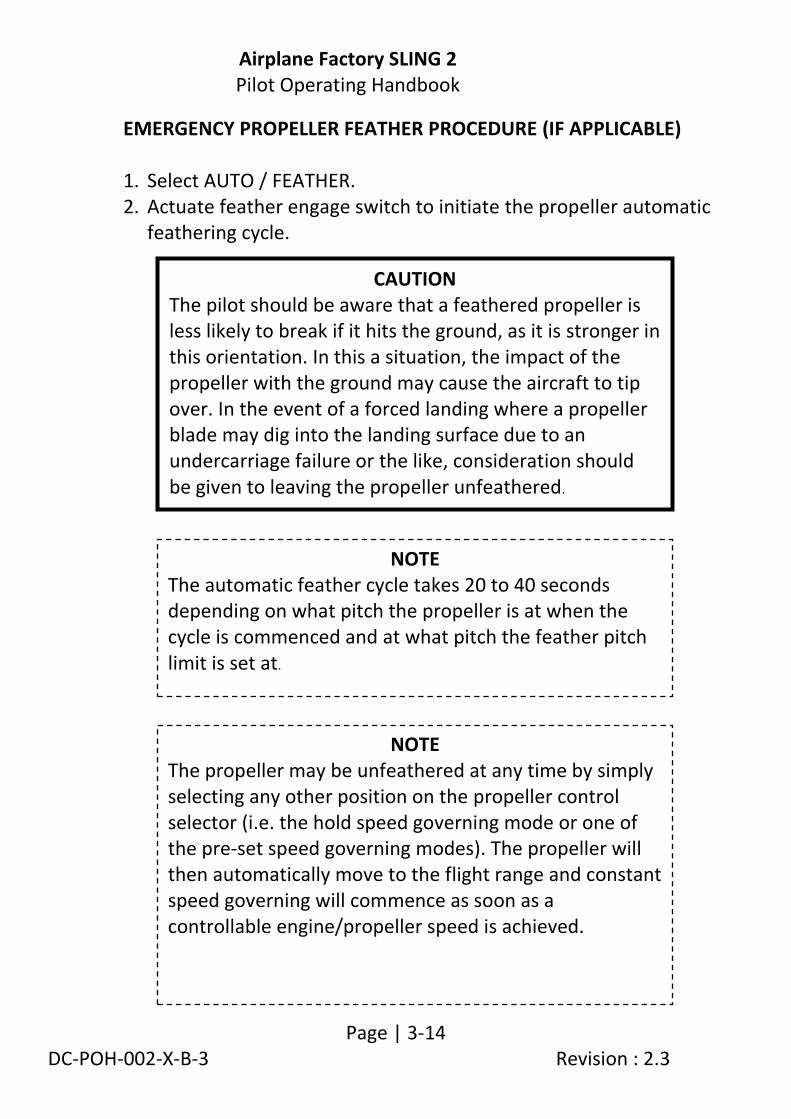
EMERGENCY PROPELLER FEATHER PROCEDURE (IF APPLICABLE) 1. Select AUTO / FEATHER. 2. Actuate feather engage switch to initiate the propeller automatic
feathering cycle.
CAUTION The pilot should be aware that a feathered propeller is less likely to break if it hits the ground, as it is stronger in this orientation. In this a situation, the impact of the propeller with the ground may cause the aircraft to tip over. In the event of a forced landing where a propeller blade may dig into the landing surface due to an undercarriage failure or the like, consideration should be given to leaving the propeller unfeathered.
NOTE The automatic feather cycle takes 20 to 40 seconds depending on what pitch the propeller is at when the cycle is commenced and at what pitch the feather pitch limit is set at.
NOTE The propeller may be unfeathered at any time by simply selecting any other position on the propeller control selector (i.e. the hold speed governing mode or one of the pre-set speed governing modes). The propeller will then automatically move to the flight range and constant speed governing will commence as soon as a controllable engine/propeller speed is achieved.

Airplane Factory SLING 2 Pilot Operating Handbook
Page | 3-15 DC-POH-002-X-B-3 Revision : 2.3
3.5.2 Precautionary landing A precautionary landing is generally carried out in cases where the pilot may be disorientated, the aircraft has no fuel reserve or possibly in bad weather conditions. 1. Choose landing area, determine wind direction. 2. Report your intention to land and the landing location via radio. 3. Perform a low altitude pass into wind, over the right-hand side of
the selected area, with flaps extended as required and thoroughly inspect the landing area.
4. Perform a circuit pattern. 5. Perform approach at increased idle with flaps fully extended. 6. Reduce power to idle when flying over the runway threshold and
touch-down at the very beginning of the selected area. 7. After stopping the aircraft switch off all switches, shut off the fuel
selector, lock the aircraft and seek assistance.
NOTE Keep the chosen area in sight during
precautionary landing.
Airplane Factory SLING 2 Pilot Operating Handbook
Page | 3-16 DC-POH-002-X-B-3 Revision : 2.3
3.5.3 Landing with a flat tyre / damaged wheel 1. If a main landing gear tyre is flat or a wheel is damaged, perform
touch-down at the lowest practical speed with the aircraft slightly banked towards the serviceable tyre / wheel. Maintain directional control during the landing run and keep the flat tyre / damaged wheel off the ground, just above or very lightly on the ground, until the lowest speed possible.
2. If the nose wheel is damaged / flat perform touch-down at the lowest practical speed and hold the nose wheel off the ground as long as possible, via elevator control.
Airplane Factory SLING 2 Pilot Operating Handbook
Page | 3-17 DC-POH-002-X-B-3 Revision : 2.3
3.6 Recovery from unintentional spin The aircraft is unlikely to enter an unintentional spin unless extreme control are applied. Unintentional spin recovery technique: 1. Throttle - idle. 2. Lateral control - ailerons neutral. 3. Rudder pedals - full rudder in direction opposite to spin 4. Rudder pedals - neutralize rudder immediately when
rotation stops. 5. Longitudinal control - neutralize control column or push
forward if necessary to lower nose, then recover from dive ensuring VNE and load factor limitations are not exceeded.
In the unlikely event that applied control inputs result in the aircraft entering a flat spin and the steps listed above do not result in recovery (following their application for a sustained period), the following technique may be implemented: 1. Throttle - set to full power. 2. Lateral control - ailerons neutral. 3. Rudder pedals - full rudder in direction opposite to spin. 4. Rudder pedals - neutralize rudder immediately when
rotation stops. 5. Throttle - reduce to idle. 6. Longitudinal control - as per step 5 (longitudinal control) above.
WARNING Intentional spins are prohibited!
NOTE Notwithstanding that installed equipment may
include GPS navigational aids, such equipment may not be used as the sole information source for
purposes of navigation unless permitted by law.
Airplane Factory SLING 2 Pilot Operating Handbook
Page | 3-18 DC-POH-002-X-B-3 Revision : 2.3
3.7 Other emergencies
3.7.1 Vibration If any abnormal aircraft vibration occurs: 1. Set engine speed to a setting where the vibration is least, if viable. 2. Land on the nearest airfield or perform a precautionary landing
according to 3.5.2.
3.7.2 EFIS System Failure
If the EFIS system freezes, otherwise fails or reacts incorrectly in flight: 1. Maintain straight and level flight utilizing other instruments and
ground references. 2. Switch the EFIS back-up battery and the EFIS main switch off (i.e.
remove power from the EFIS). 3. Following a 3 second delay, apply power to the EFIS, maintaining
straight and level flight at all times. 4. Maintain straight and level for at least another 15 seconds while the
system boots up (when the system reboots, the navigation system(s) should remain active and any active routes (preceding the failure) should continue to be shown).
In case the system fails to re-boot properly:
5. Execute a precautionary landing at the first safe opportunity and
have the instrument repaired.

Airplane Factory SLING 2 Pilot Operating Handbook
Page | 3-19 DC-POH-002-X-B-3 Revision : 2.3
3.7.3 Carburetor icing Carburetor icing is evidenced through a decrease in engine power and an increase of engine temperatures. To recover the engine power, the following procedure is recommended: 1. Speed - 75 KIAS 2. Throttle - 1/3 power. 3. If possible leave the (icing) area. 4. Increase the engine power gradually up to cruise conditions after
1 to 2 minutes. If you fail to recover engine power, land at the nearest airfield (if possible) or, depending on the circumstances, perform a precautionary landing according to paragraph 3.5.2.
Airplane Factory SLING 2 Pilot Operating Handbook
Page | 3-20 DC-POH-002-X-B-3 Revision : 2.3
3.7.4 Alternator / charge system failure
For aircraft fitted with the 912 iS or 914 UL engine please refer to the supplement at the end of this manual Failure of the alternator / charge system will result in the main battery not being charged. Alternator (914 UL / 912 ULS) failure is evidenced by the illumination of the (red) alternator charge warning light.
1. EFIS main switch - off. 2. All non-critical electrical equipment - off.
(navigation, strobe, taxi, landing lights etc.). 3. Auxiliary fuel pump - off. 4. Autopilot - off. 5. Propeller (if applicable) - AUTO/CLIMB (or
as desired). 6. When propeller (if applicable) governs at climb setting - MAN. 7. Propeller switch (if applicable) - off. 8. Set EFIS brightness to minimum. 9. Restrict / avoid the use of the elevator trim control. Restrict radio
transmission to minimum / only that which is absolutely necessary. 10. Land as soon as possible.
NOTE When landing with adequate battery power remaining (to power both the propeller motor (if applicable) and (if required for 912 ULS) the electric fuel pump(s)) the propeller (if applicable) can be re-energized and selections made as applicable.
NOTE The 912 ULS engine operation is independent from the aircraft
main battery (except for start motor operation) / alternator. The engine will continue running after an alternator failure and / or
with a depleted battery.

Airplane Factory SLING 2 Pilot Operating Handbook
Page | 3-21 DC-POH-002-X-B-3 Revision : 2.3
3.7.5 Main bus power failure
For aircraft fitted with a 914 UL or 912 iS engine refer to the applicable supplement at the end of this manual. Refer to paragraph 7.17, under Main bus, for a list of equipment affected by a loss of power to the main bus.
1. The EFIS should automatically switch over to the EFIS
back-up battery supply , provided that the EFIS battery back-up switch is on (if not, switch on the EFIS battery back-up switch) and the back-up battery contains adequate charge.
2. Switch off all main bus connected equipment / switches. 3. Land as soon as possible.

Airplane Factory SLING 2 Pilot Operating Handbook
Page | 4-1/4-2 DC-POH-002-X-B-3 Revision : 2.3
4. NORMAL PROCEDURES
4.1 Introduction .............................................................................................. 4-3
4.2 Speeds for normal operation .................................................................... 4-3
4.3 Use of taxi, landing, strobe and navigation lights ..................................... 4-4
4.4 Pre-flight check ......................................................................................... 4-5
4.5 Engine start ............................................................................................. 4-10
4.6 Taxi ......................................................................................................... 4-13
4.7 Normal take-off ...................................................................................... 4-14
4.8 Climb....................................................................................................... 4-16
4.9 Cruise ...................................................................................................... 4-17
4.10 Descend .................................................................................................. 4-17
4.11 Approach ................................................................................................ 4-18
4.12 Normal landing ....................................................................................... 4-19
4.13 Baulked landing procedures ................................................................... 4-20
4.14 Short field take-off and landing procedures ........................................... 4-20
4.15 Engine shutdown .................................................................................... 4-21
4.16 Aircraft parking and tie-down ................................................................. 4-22

Airplane Factory SLING 2 Pilot Operating Handbook
Page | 4-3 DC-POH-002-X-B-3 Revision : 2.3
4.1 Introduction
This section provides checklists and recommended procedures for normal operation of the airplane.
4.2 Speeds for normal operation
Unless otherwise noted, the following speeds are based on a maximum weight of 700 kg (1 543.23 lb).
SPEED KIAS REMARKS
Vx Best Angle of Climb Speed
65
The speed (at MAUW, flaps fully retracted) which results in the greatest altitude gain over a given horizontal distance (i.e. largest climb angle).
VY Best Rate of Climb Speed
74 The speed (at MAUW, flaps fully retracted) which results in the greatest altitude gain over a given time period.
VROT Rotation Speed
40
The speed at which the aircraft should be rotated about the pitch axis during take-off (i.e. the speed at which the nose wheel is lifted off the ground).
VLOF Lift-off Speed
48 The speed at which the aircraft generally lifts off from the ground during take-off.
Cruise Climb 75 to 90
Approach speed - long finals
65 to 75
VREF Threshold crossing speed
≥ 55 Indicated airspeed at 15 m (50 ft) above threshold, which is not less than 1.3VSO.

Airplane Factory SLING 2 Pilot Operating Handbook
Page | 4-4 DC-POH-002-X-B-3 Revision : 2.3
4.3 Use of taxi, landing, strobe and navigation lights Refer to paragraph 7.22. Taxi lights should be used as appropriate and their use should be incorporated in the applicable (taxi and before take-off) procedures as required. Give consideration to taxi lights as an aid to enhancing the aircraft’s visibility to other traffic / pedestrians / wildlife. Landing lights should be used as appropriate and their use should be incorporated in the applicable (before take-off, take-off, climb, approach and landing) procedures as required. Give consideration to landing lights as an aid to enhancing the aircraft’s visibility to other traffic / pedestrians / wildlife.
Strobe and navigation lights should be used as appropriate and their use should be incorporated in the following (normal) procedures as required. Give consideration to using the strobe light as an indicator / warning of imminent engine start (i.e. switch on the strobe before starting the engine).

Airplane Factory SLING 2 Pilot Operating Handbook
Page | 4-5 DC-POH-002-X-B-3 Revision : 2.3
4.4 Pre-flight check
Carry out the pre-flight inspection every day prior to the first fight. Pre-flight inspections must also be performed after any accident, incident, maintenance activity, assembly of any aircraft component or suchlike. Incomplete or careless inspection can result in an accident. Carry out the inspection following the instructions in the Inspection Check List.
Inspection Check List 1. Cabin - Magnetos / ignition - off. - Master switch - on - Fuel level indicator - verify fuel quantity. - Flaps - move to full down position. - Master switch - off. - Avionics - verify condition. - Control System - visual inspection, free movement up to
stops, verify function. - Canopy - attachment condition, clean. - Cockpit - check for loose objects. - Fire extinguisher - verify present and valid. - Documentation - verify present and valid.
NOTE The word “condition” in the instructions means a visual
inspection of surface for damage deformations, scratching, chafing, corrosion or other damages, which
may lead to flight safety degradation.

Airplane Factory SLING 2 Pilot Operating Handbook
Page | 4-6 DC-POH-002-X-B-3 Revision : 2.3
2. Nose Section and Nose Gear - Engine cowling condition - check. - Propeller and spinner condition - check. - Air intakes - check. - Radiators - check. - Engine mount and exhaust manifold condition- check. - Oil and coolant quantity check - check. - Visual inspection of fuel & electrical system - check. - Engine checks as per Rotax manual - complete. - Other actions according to the engine manual - Parachute cover - if fitted check sealed
and secure. - Tyre - condition, inflation,
wear. - Wheels - security, general
condition. - Chocks and tie-down ropes - remove. - Suspension and undercarriage - check and test.
CAUTION In case of long-term parking it is recommended to turn the engine
over several times (ignition / magnetos OFF!) by turning the propeller in order to prime the lubrication system. Always handle
the propeller blade area with the palm of your hand i.e. do not grasp only the blade edge with your fingers.
Airplane Factory SLING 2 Pilot Operating Handbook
Page | 4-7 DC-POH-002-X-B-3 Revision : 2.3
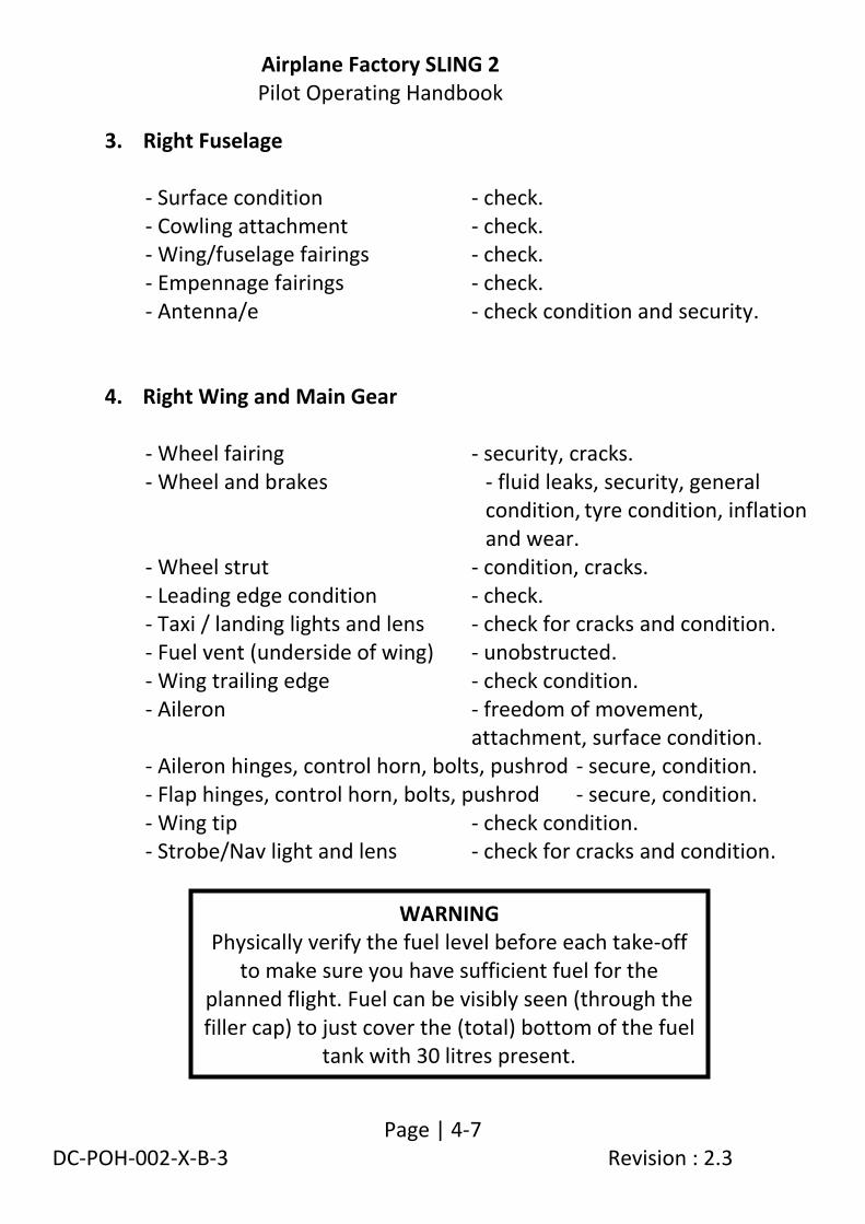
3. Right Fuselage
- Surface condition - check. - Cowling attachment - check. - Wing/fuselage fairings - check. - Empennage fairings - check. - Antenna/e - check condition and security.
4. Right Wing and Main Gear
- Wheel fairing - security, cracks. - Wheel and brakes - fluid leaks, security, general
condition, tyre condition, inflation and wear.
- Wheel strut - condition, cracks. - Leading edge condition - check. - Taxi / landing lights and lens - check for cracks and condition. - Fuel vent (underside of wing) - unobstructed. - Wing trailing edge - check condition. - Aileron - freedom of movement,
attachment, surface condition. - Aileron hinges, control horn, bolts, pushrod - secure, condition. - Flap hinges, control horn, bolts, pushrod - secure, condition. - Wing tip - check condition. - Strobe/Nav light and lens - check for cracks and condition.
WARNING Physically verify the fuel level before each take-off
to make sure you have sufficient fuel for the planned flight. Fuel can be visibly seen (through the filler cap) to just cover the (total) bottom of the fuel
tank with 30 litres present.

Airplane Factory SLING 2 Pilot Operating Handbook
Page | 4-8 DC-POH-002-X-B-3 Revision : 2.3
5. Empennage
- Tie-down rope - removed. - Horizontal and vertical stabilizers - check condition. - Elevator and tab - condition and movement. - Rudder - condition and movement. - Hinges, control horns, bolts, pushrod - condition and secure. - Strobe light - condition.
6. Left Fuselage
- Surface condition - check. - Cowling attachment - check. - Wing/fuselage fairings - check. - Empennage fairings - check. - Antenna/e - check condition and security.

Airplane Factory SLING 2 Pilot Operating Handbook
Page | 4-9 DC-POH-002-X-B-3 Revision : 2.3
7. Left Wing
- Wheel fairing - security, cracks. - Wheel and brakes - fluid leaks, security, general
condition, tyre condition, inflation and wear.
- Wheel strut - condition, cracks. - Leading edge condition - check. - Taxi / landing lights and lens - check for cracks and condition. - Fuel vent (underside of wing) - unobstructed. - Wing trailing edge - check condition. - Aileron - freedom of movement,
attachment, surface condition. - Aileron hinges, control horn, bolts, pushrod - secure, condition. - Flap hinges, control horn, bolts, pushrod - secure, condition. - Wing tip - check condition. - Strobe/Nav light and lens - check for cracks and condition. - Pitot tube - security, unobstructed, remove
cover.
WARNING Physically verify the fuel level before each take-off
to make sure you have sufficient fuel for the planned flight. Fuel can be visibly seen (through the filler cap) to just cover the (total) bottom of the fuel
tank with 30 litres present.

Airplane Factory SLING 2 Pilot Operating Handbook
Page | 4-10 DC-POH-002-X-B-3 Revision : 2.3
4.5 Engine start
Reference should be made to the operator’s manual for the Rotax 914 UL , 912 iS or 912 ULS engine, as the case may be, for operational guidelines and instructions. These should be incorporated into the normal or emergency procedures as applicable.
4.5.1 Before starting engine
1. Pre-flight inspection - completed. 2. Emergency equipment - on board. 3. Passenger - briefed. 4. Seats, seatbelt and harnesses - adjust and secure. 5. Brakes - on.
4.5.2 Engine start
If a Rotax 912 iS or 914 UL engine is installed (rather than a Rotax 912 ULS engine) please refer to the supplement at the end of this manual. 1. Master switch - on. 2. EFIS back-up battery - on, verify EFIS on and back-up
battery voltage.
CAUTION In case of long-term parking it is recommended to turn the engine
over several times (Ignition / magnetos OFF!) by turning the propeller in order to prime the lubrication system. Always handle
the propeller blade area with the palm of your hand i.e. do not grasp only the blade edge with your fingers.
CAUTION Observe temperature limits for engine start as specified in
paragraph 2.14.

Airplane Factory SLING 2 Pilot Operating Handbook
Page | 4-11 DC-POH-002-X-B-3 Revision : 2.3
3. Propeller switch (if applicable) - on. 4. Propeller (if applicable) - AUTO. 5. Magneto / ignition switches - on. 6. Fuel selector - select emptiest tank (if not
empty). 7. Electric fuel pumps (both) -on (912 iS, 914 UL). 8. Choke (cold engine) - pull to open and gradually release
after engine start (912 ULS, 914 UL). 9. Throttle - closed if choke used, cracked just
open if not. 10. Propeller area - clear of people and obstructions. 11. Starter - engage (maximum 10 seconds). Immediately after start-up: 12. Throttle - adjust for smooth running
(approximately 2000 rpm). 13. Oil pressure - increase within 10 seconds. 14. EFIS switch - on and verify battery charging. 15. Avionics master switch - on. 16. Warm engine - 2 000 rpm for 2 minutes, then
2 500 rpm until oil temp is 50 °C (122 °F).
CAUTION The starter should be activated for a maximum of 10 seconds, followed by 2 minute pause to allow the starter to cool. Verify the oil pressure, which should increase within 10 seconds. Increase the engine speed only if oil pressure is steady above 2 bar (29 psi). At an engine start with low oil temperature continue to watch the oil pressure as it could drop again due to the increased resistance in the suction line. Increase engine rpm only as required to keep oil pressure steady. To avoid shock loading, start the engine with the throttle lever set to idle or 10% open at maximum, then wait 3 seconds for engine to reach constant speed before accelerating engine rpm.

Airplane Factory SLING 2 Pilot Operating Handbook
Page | 4-12 DC-POH-002-X-B-3 Revision : 2.3
4.5.3 Engine warm up, engine check Prior to an engine check, block the main wheels with wheel chocks or ensure that the park brake is on. Initially warm up the engine at 2 000 rpm for approximately 2 minutes, then continue at 2 500 rpm until oil temperature reaches 50°C (122°F). The warm up period depends on ambient air temperature. Verify both ignition circuits at 4 000 rpm (912 ULS / 914 UL). The engine speed (rpm) drop when either magneto is switched off should not exceed 300 rpm (912 ULS / 914 UL). The maximum difference (in rpm drop) between magnetos / ignition circuits should not exceed 115 rpm (912 ULS / 914 UL). For verification of ignition circuits on an aircraft fitted with a 912 iS engine, refer to the applicable supplement at the end of this manual. Set maximum power for verification of maximum engine speed (rpm) with given propeller and engine parameters (temperatures and pressures). Check acceleration from idle to maximum power. If necessary, cool the engine at 3 000 rpm (approximately 2 minutes) before shutdown.
NOTE Only one ignition circuit (at a time) should be switched on/off
during ignition/magneto check.
CAUTION The engine check should be performed with the aircraft heading
upwind and not on loose terrain (the propeller may suck grit which can damage the leading edges of blades).

Airplane Factory SLING 2 Pilot Operating Handbook
Page | 4-13 DC-POH-002-X-B-3 Revision : 2.3
4.6 Taxi
1. Fuel selector - switch tank (to fullest tank). 2. Flaps - up. 3. Brakes - off (carefully verify that the stop brake
valve (park brake) is off). 4. Controls - neutral position, or as required for wind. 5. Power and brakes - as required. 6. Brakes -verify. 7. Instruments -verify.
Apply power and brakes as needed. Apply brakes to control movement on ground. Taxi carefully when wind velocity exceeds 15 knots. Hold the control stick in neutral position or as required, using conventional techniques.

Airplane Factory SLING 2 Pilot Operating Handbook
Page | 4-14 DC-POH-002-X-B-3 Revision : 2.3
4.7 Normal take-off
4.7.1 Before take-off
1. Controls - verify full and free movement,
directions. 2. Trim - neutral. 3. Choke - off (912 ULS / 914 UL). 4. Flaps - as required (typically 1 notch). 5. Fuel quantity - confirm. 6. Fuel selector - fullest tank. 7. Electric fuel pump - on (912 ULS).
Auxiliary electric fuel pump - on (912 iS / 914 UL). 8. Circuit breakers - all in. 9. Instruments - verify all. 10 Altimeter - set QNH / QFE. 11. Switches - verify, as required. 12. Power and ignition - verify magnetos at 4 000rpm, max
difference 115 rpm, max drop 300 rpm (912 ULS / 914 UL).
13. Propeller check (if applicable) - set 4000 engine rpm, select MAN, set fully coarse and verify rpm reduction/coarse indicator illuminates orange, set fully fine and observe rpm increase/fine indicator illuminates orange.
14. Propeller (if applicable) - AUTO / TO. 15. Engine parameters - verify temperatures, pressures,
current/voltage. 16. Canopy - closed and latched. 17. Safety harnesses - on and tight. 18. Ballistic parachute (if fitted) - remove.
handle lock pin

Airplane Factory SLING 2 Pilot Operating Handbook
Page | 4-15 DC-POH-002-X-B-3 Revision : 2.3
4.7.2 Take-off 1. Propeller (if applicable) - AUTO / TO. 2. Take-off power - throttle fully forward (max. 5 800
rpm for 5 minutes). 3. Engine speed - verify rpm (5 500 to 5 800 rpm). 4. Instruments within limits - verify. 5. Rotate - 40 KIAS. 6. Airplane lift-off - 48 KIAS. 7. Wing flaps - retract when speed of 65 KIAS is
reached, at minimum height of 300 ft.
8. Electric fuel pump - off (912 ULS)(minimum 300 ft) Auxiliary electric fuel pump - off (912 iS/914 UL)(300 ft
minimum). 9. Brakes - apply briefly brakes to stop wheel
rotation. 10. Transition to climb.
CAUTION
Ensure that engine oil temperature is above 50 °C prior to take off. Climbing with engine at 5 800 rpm is permissible for 5 minutes. Thereafter a maximum continuous engine rpm of 5 500 applies.
WARNING Take-off is prohibited if:
The engine is running unsteadily or intermittently.
The engine parameters (instrument indications) are outside operational limits.
The crosswind velocity exceeds permitted limits (see 2.5).

Airplane Factory SLING 2 Pilot Operating Handbook
Page | 4-16 DC-POH-002-X-B-3 Revision : 2.3
4.8 Climb 1. Propeller (if applicable) - AUTO / CLIMB. 2. Throttle - Maximum take-off power, 5 800 rpm (for
maximum 5 minutes). - Maximum continuous power, 5 500 rpm. 3. Airspeed - VX = 65 KIAS. - VY = 74 KIAS. - cruise climb = 75 to 90 KIAS. 4. Trim - as required. 5. Instruments -verify: - oil temperature and pressure. - cylinder temperature within limits.
CAUTION If the cylinder head temperature or oil temperature approach their limits, reduce the climb angle to increase airspeed and
thus fulfill the limits.
CAUTION Climbing with engine at 5 800 rpm is permissible for 5 minutes. Thereafter a maximum continuous engine rpm of 5 500 applies.

Airplane Factory SLING 2 Pilot Operating Handbook
Page | 4-17 DC-POH-002-X-B-3 Revision : 2.3
4.9 Cruise 1. Propeller (if applicable) AUTO/CRUISE.
Refer to section 5 for recommended cruising figures.
4.10 Descend Optimum glide speed - 72 KIAS.
WARNING The fuel lift pipe in each fuel tank is situated adjacent to the lower inside wall of the tank. The aircraft should at no time be subjected to a sustained side slip towards a
near empty fuel tank (i.e. - wing with near empty tank down) as, despite the baffling, this may have the consequence that the fuel runs towards the outer edge of the tank exposing the fuel lift pipe (to suck air), thereby starving the engine of
fuel leading to engine stoppage. This poses a particular threat when at low altitude,
typically prior to landing.
WARNING If a fuel lift pipe is exposed to air, the pump will suck air into the engine (from the empty tank) and engine stoppage will result. When one tank is empty, or close to empty, the fuel selector valve should be switched to the fullest tank.
Avoid operation below the normal operational oil temperature (90 to 110 °C / 194 to 230 °F).
CAUTION It is not advisable to reduce the engine throttle control lever to minimum on final approach or when descending from very high altitude. In such cases the engine can become over-cooled, although unlikely, and a loss of power may occur. Descent at increased idle (approximately 3000 rpm), speed between 65 to 85 KIAS and verify
that the engine instruments indicate values within permitted limits.
Airplane Factory SLING 2 Pilot Operating Handbook
Page | 4-18 DC-POH-002-X-B-3 Revision : 2.3
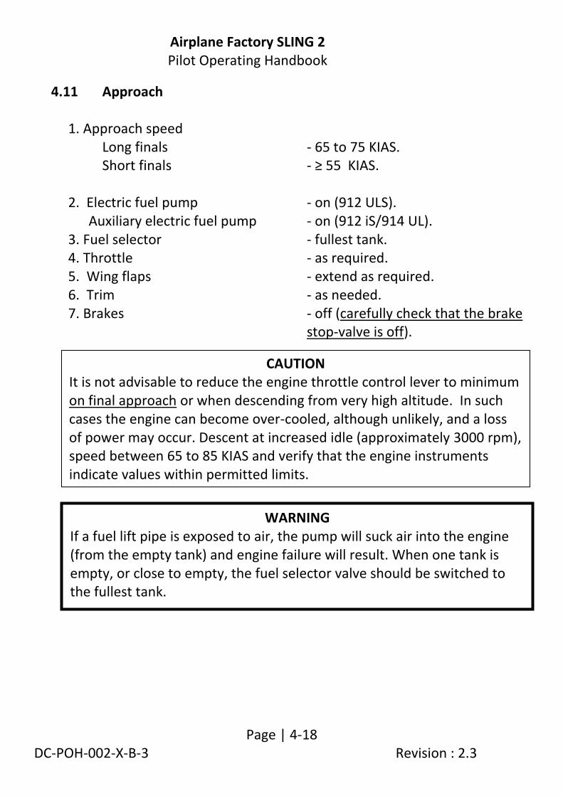
4.11 Approach 1. Approach speed
Long finals - 65 to 75 KIAS. Short finals - ≥ 55 KIAS.
2. Electric fuel pump - on (912 ULS). Auxiliary electric fuel pump - on (912 iS/914 UL). 3. Fuel selector - fullest tank. 4. Throttle - as required. 5. Wing flaps - extend as required. 6. Trim - as needed. 7. Brakes - off (carefully check that the brake
stop-valve is off).
CAUTION It is not advisable to reduce the engine throttle control lever to minimum on final approach or when descending from very high altitude. In such cases the engine can become over-cooled, although unlikely, and a loss of power may occur. Descent at increased idle (approximately 3000 rpm), speed between 65 to 85 KIAS and verify that the engine instruments indicate values within permitted limits.
WARNING If a fuel lift pipe is exposed to air, the pump will suck air into the engine (from the empty tank) and engine failure will result. When one tank is empty, or close to empty, the fuel selector valve should be switched to the fullest tank.

Airplane Factory SLING 2 Pilot Operating Handbook
Page | 4-19 DC-POH-002-X-B-3 Revision : 2.3
4.12 Normal landing
4.12.1 Before landing
1. Propeller (if applicable) - AUTO / TO. 2. Throttle - as required. 3. Airspeed - ≥ 55 KIAS. 4. Wing flaps - extend as required. 5. Trim - as required. 6. Brakes - off (carefully check that the brake stop-
valve is off).
4.12.2 Landing
1. Throttle - as required. 2. Controls - flare to minimum flying speed, touch-
down on main wheels. 3. Nose wheel - gently lower to ground. 4. Apply brakes - as required (after the nose wheel touch-
down) for controlled slowing down.

Airplane Factory SLING 2 Pilot Operating Handbook
Page | 4-20 DC-POH-002-X-B-3 Revision : 2.3
4.12.3 After landing 1. Engine speed - set as required for taxi. 2. Wing flaps - retract.
4.13 Baulked landing procedures 1. Throttle - full power (maximum 5 800 rpm for
5 minutes). 2. Trim - as required. 3. Wing flaps - retract to 50% as soon as possible and
retract fully when reaching 65 knots (at 300 ft minimum height).
4. Electric fuel pump - off (912 ULS) (300 ft minimum). Auxiliary electric fuel pump - off (912 iS / 914 UL) (300 ft minimum). 5. Propeller (if applicable) - AUTO / CLIMB (minimum 300 ft). 6. Trim - adjust. 7. Repeat circuit pattern.
4.14 Short field take-off and landing procedures
Not considered necessary. Ordinary short field procedures may be used if pilot deems it appropriate.
CAUTION Rapid engine cooling should be avoided during operation. This especially
happens during aircraft descent, taxi, low engine rpm or at engine shutdown immediately after landing. Under normal conditions the engine temperatures stabilize during descent and taxi at values suitable to stop
the engine (by switching the ignition off) as soon as aircraft is stopped. If necessary (elevated engine operating temperatures), cool (for minimum
2 minutes) the engine at approximately 3 000 rpm to stabilize the temperatures prior to engine shut down.

Airplane Factory SLING 2 Pilot Operating Handbook
Page | 4-21 DC-POH-002-X-B-3 Revision : 2.3
4.15 Engine shutdown
Note: For Rotax 912 iS engine at least 5 minutes must elapse between landing and shutting off the engine.
1. Engine speed - idle. 2. Instruments - engine parameters within limits. 3. Avionics master switch - off. 4. Electric fuel pump - off (912 ULS).
Electric fuel pumps (both) - off (912 iS / 914 UL). 5. Magnetos / ignition - off. 6. Electrical switches - off. 7. EFIS - off, battery back-up off. 8. Master switch - off. 9. Fuel selector - off.
CAUTION Rapid engine cooling should be avoided during operation. This especially
happens during aircraft descent, taxi, low engine rpm or at engine shutdown immediately after landing. Under normal conditions the engine temperatures stabilize during descent and taxi at values suitable to stop
the engine (by switching the ignition off) as soon as aircraft is stopped. If necessary (elevated engine operating temperatures), cool (for minimum 2
minutes) the engine at approximately 3 000 rpm to stabilize the temperatures prior to engine shut down.

Airplane Factory SLING 2 Pilot Operating Handbook
Page | 4-22 DC-POH-002-X-B-3 Revision : 2.3
4.16 Aircraft parking and tie-down 1. Site - Park the aircraft on as level an area as
possible. 2. Ignition/ magneto switches - off. 3. Master switch - off. 4. Fuel selector - off. 5. Parking brake - use as necessary. 6. Canopy - close, lock as necessary. 7. Secure the airplane.
NOTE Use the anchor eyes on the wings and fuselage rear section to secure the
airplane. Move control stick forward and secure it together with the rudder pedals if high winds are expected. Make sure that the cockpit
canopy is properly closed and locked.
NOTE It is recommended that the parking brake (shut-off valve) be utilized for
short-period parking only. If the airplane is to be parked for long periods it is advisable to use not only the parking brake, but also wheel chocks.

Airplane Factory SLING 2 Pilot Operating Handbook
Page | 5-1/5-2 DC-POH-002-X-B-3 Revision : 2.3
5. PERFORMANCE
5.1 Take-off and landing distance ................................................................... 5-3
5.2 Rate of climb ............................................................................................. 5-4
5.3 Cruise speeds (with fixed pitch propeller) ................................................ 5-5
5.4 Fuel consumption ..................................................................................... 5-6
5.5 Airspeed indicator system calibration ...................................................... 5-7

Airplane Factory SLING 2 Pilot Operating Handbook
Page | 5-3 DC-POH-002-X-B-3 Revision : 2.3
The presented data has been computed from actual flight tests with the aircraft and engine in good condition and using average piloting techniques.
If not stated otherwise, the performance stated in this section is valid for maximum take-off weight (700 kg/1 540 lbs) and under ISA conditions.
The performance shown in this section is valid for aircraft fitted with a ROTAX 912 ULS 73.5 kW (98.6 hp).
5.1 Take-off and landing distance
Take-off distances:
Surface Take-off run Take-off distance over 15m (50 ft) obstacle
Concrete 140 m / 460 ft 280 m / 920 ft
Grass 160 m / 525 ft 300 m / 985 ft
Landing distances:
Surface Landing run (braked)
Landing distance over 15 m (50 ft) obstacle
Concrete 90 m / 295 ft 260 m / 855 ft
Grass 90 m / 295 ft 260 m / 855 ft
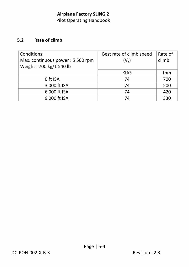
Airplane Factory SLING 2 Pilot Operating Handbook
Page | 5-4 DC-POH-002-X-B-3 Revision : 2.3
5.2 Rate of climb
Conditions: Max. continuous power : 5 500 rpm Weight : 700 kg/1 540 lb
Best rate of climb speed (VY)
Rate of climb
KIAS fpm
0 ft ISA 74 700 3 000 ft ISA 74 500
6 000 ft ISA 74 420
9 000 ft ISA 74 330

Airplane Factory SLING 2 Pilot Operating Handbook
Page | 5-5 DC-POH-002-X-B-3 Revision : 2.3
5.3 Cruise speeds (with fixed pitch propeller)
Altitude [ft ISA]
Engine speed [rpm]
KIAS
KTAS
100
4 500 78 79
4 800 93 94
5 000 98 99
5 300 103 105
5 500 109 111
3 000
4 500 69 73
4 800 84 90
5 000 95 102
5 300 101 107
5 500 105 111
6 000
4 500 62 70
4 800 77 86
5 000 87 97
5 300 95 105
5 500 98 112
9 000
4 500 60 70
4 800 71 85
5 000 84 96
5 300 88 102
5 500 91 105

Airplane Factory SLING 2 Pilot Operating Handbook
Page | 5-6 DC-POH-002-X-B-3 Revision : 2.3
5.4 Fuel consumption
Altitude [ft ISA] 3 000
Fuel quantity
[ l ] 150
[US gallons] 39.63
Engine speed
[rpm] 4 500 4 800 5 000 5 300 5 500
Fuel consumption
[l/h] 14 16 18 20 21
[US gallons] 3.70 4.23 4.76 5.29 5.55
Airspeed [KIAS] 73 90 102 107 111
Endurance [hh:mm] 10:40 9:20 08:20 07:30 07:10
Range (no reserve)
[nm] 782 843 850 802 792

Airplane Factory SLING 2 Pilot Operating Handbook
Page | 5-7 DC-POH-002-X-B-3 Revision : 2.3
5.5 Airspeed indicator system calibration
IAS [knots] CAS [knots] (average)
CAS [knots] (this aircraft)
25 28
30 33
35 37
40 41
45 45
50 50
55 55
60 60
65 65
70 70
75 75
80 80
85 85
90 90
95 95
100 100
105 105 110 110
115 115
120 120
125 125
130 130
135 135

Airplane Factory SLING 2 Pilot Operating Handbook
Page | 6-1/6-2 DC-POH-002-X-B-3 Revision : 2.3
6. WEIGHT AND BALANCE
6.1 Installed equipment list ............................................................................ 6-3
6.2 Center of gravity (CG) range ..................................................................... 6-4
6.3 Determination of aircraft GC .................................................................... 6-6
6.4 Empty CG determination .......................................................................... 6-7
6.5 Blank for and graph for use ...................................................................... 6-8

Airplane Factory SLING 2 Pilot Operating Handbook
Page | 6-3 DC-POH-002-X-B-3 Revision : 2.3
This section contains weight and balance records and the payload range for safe operating of the Sling 2.
6.1 Installed equipment list
MGL multifunction glass cockpit instrument - Challenger iEFIS.
MGL V6 COM radio.
Mode S transponder (optional). Analogue altimeter, airspeed indicator, ball type slip indicator.
Magnetic compass.
Electric trim system.
Electric flap actuator.

Airplane Factory SLING 2 Pilot Operating Handbook
Page | 6-4 DC-POH-002-X-B-3 Revision : 2.3
6.2 Center of gravity (CG) range Operating CG range and allowable GC envelope
GC range is 1 635 mm (5.364 ft) to 1 807.75 mm (5.931 ft) aft of the reference datum (20 to 33% of MAC).
The leading edge of the MAC is 1 366 mm (4.482 ft) aft of the reference datum.
The MAC is 1 339 mm (4.393 ft).
DIMENSIONS ON THIS DRAWING ARE IN MILLIMETRES

Airplane Factory SLING 2 Pilot Operating Handbook
Page | 6-5 DC-POH-002-X-B-3 Revision : 2.3
WARNING Aircraft CG and MAUW limitations must be adhered
to at all times.
WARNING For each flight the most forward CG (i.e. with take-off fuel) and the most rearward CG (i.e. with landing fuel) must be calculated (to be
within aircraft CG range / limits).
FLIGHT ALLOWED IN SHADED AREA ONLY
771.62
881.85
992.08
1102.31
1212.54
1322.77
1433
1543.23
Air
craf
t M
ass
[lb
]
1763.7
1653.47

Airplane Factory SLING 2 Pilot Operating Handbook
Page | 6-6 DC-POH-002-X-B-3 Revision : 2.3
6.3 Determination of aircraft GC Weight and balance report lists:
Empty CG check.
Forward CG check (example).
Rear CG check (example).
Blank CG form.
CG formulae:
( )
( )
The aircraft empty CG is determined in a conventional manner by weighing the aircraft whilst it is standing level. (Refer to the aircraft maintenance manual for instructions on aircraft leveling and weighing).
WARNING For each flight the most forward CG (i.e. with take-off fuel) and the most rearward CG (i.e. with landing fuel) must be calculated (to be
within aircraft CG range / limits).

Airplane Factory SLING 2 Pilot Operating Handbook
Page | 6-7 DC-POH-002-X-B-3 Revision : 2.3
6.4 Empty CG determination
ITEM WEIGHT
[kg (lb)]
ARM
[mm (ft)]
MOMENT
(weight x arm)
[kg.mm (lb.ft)]
Air
craf
t Em
pty
CG
Right Main Wheel
WR = LR = 1 959 (6.427)
Left Main Wheel
WL = LL = 1 959 (6.427)
Nose Wheel WN = LN = 548 (1.797)
Computed empty CG
Empty weight:
WE = …………..kg (lb)
CG = ……….. mm (ft)
(…………% MAC)
Aircraft moment :
Maximum all up (take-off) weight = 700 kg (1 540 lb).
Maximum useful load (example): Wmax useful = WMAUW - WE
= 700 kg (1 540 lb) -370 kg (815.7 lb) = 330 kg (727.5 lb)

Airplane Factory SLING 2 Pilot Operating Handbook
Page | 6-8 DC-POH-002-X-B-3 Revision : 2.3
6.5 Blank for and graph for use
WEIGHT
[kg (lb)]
ARM
[mm (ft)]
MOMENT
(weight x arm)
[kg.mm (lb.ft)]
PILOT & PASSENGER
1 959 (6.427)
BAGGAGE (FRONT)
2 508 (8.228)
BAGGAGE
(REAR)
2 896(9.501)
FUEL 1 511 (4.957)
ADD EMPTY VALUES
TOTAL
WT = MT =
CG = %MAC

Airplane Factory SLING 2 Pilot Operating Handbook
Page | 6-9 DC-POH-002-X-B-3 Revision : 2.3
771.62
881.85
992.08
1102.31
1212.54
1322.77
1433
1763.7
Air
craf
t M
ass
[lb
]
1543.23
1653.47

Airplane Factory SLING 2 Pilot Operating Handbook
Page | 7-1/7-2 DC-POH-002-X-B-3 Revision : 2.3
7. SYSTEMS
7.1 Airframe .................................................................................................... 7-3
7.2 Control system / Pilot controls ................................................................. 7-3
7.3 Landing gear ............................................................................................. 7-6
7.4 Brake system ............................................................................................ 7-7
7.5 Safety harness .......................................................................................... 7-8
7.6 Baggage compartment ............................................................................. 7-8
7.7 Canopy ...................................................................................................... 7-9
7.8 Pitot and static systems .......................................................................... 7-10
7.9 Cockpit layout ......................................................................................... 7-11
7.10 Instruments and Avionics ....................................................................... 7-13
7.11 Flap and elevator trim systems ............................................................... 7-18
7.12 Minimum instruments and equipment required for flight: .................... 7-19
7.13 Engine ..................................................................................................... 7-20
7.14 Cooling system (914 UL / 912 ULS / 912 iS) ............................................ 7-20
7.15 Throttle and Choke ................................................................................. 7-21
7.16 Carburetor pre-heating/anti-ice ............................................................. 7-22
7.17 Electrical System ..................................................................................... 7-23
7.18 Propeller ................................................................................................. 7-31
7.19 Fuel system ............................................................................................. 7-32
7.20 Lubrication system .................................................................................. 7-34
7.21 Autopilot system..................................................................................... 7-35
7.22 Position, anti-collision, taxi and landing lights ........................................ 7-36
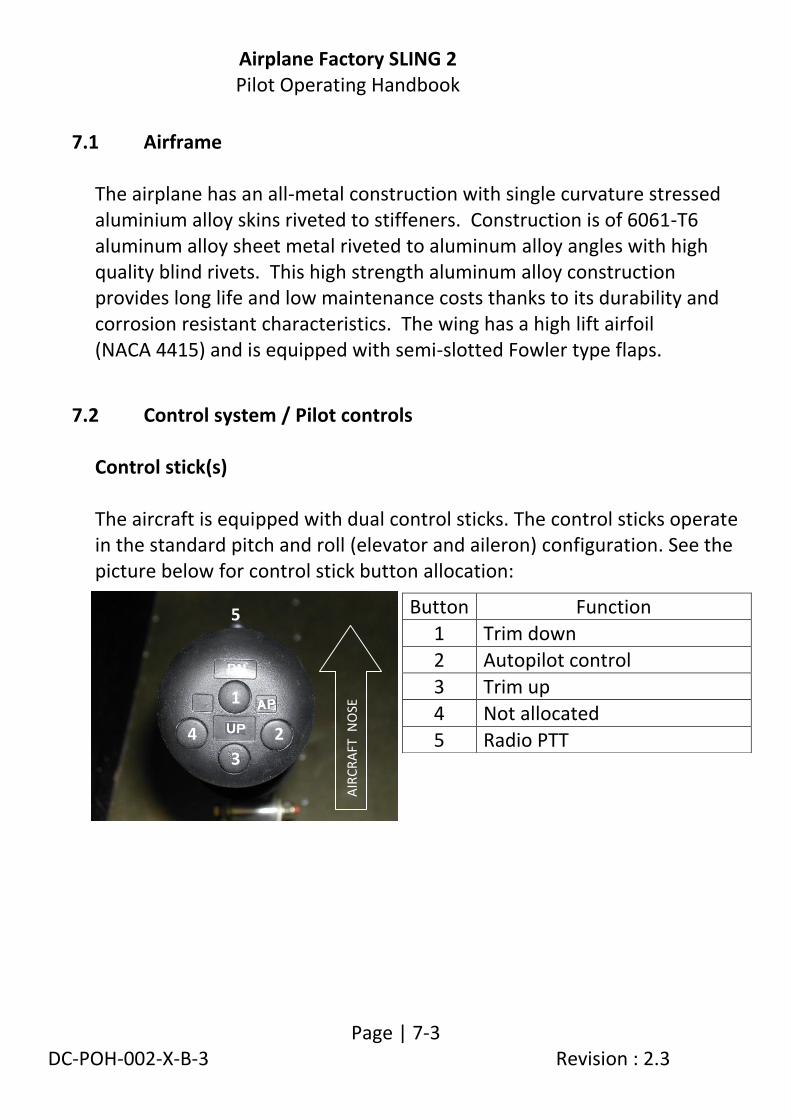
Airplane Factory SLING 2 Pilot Operating Handbook
Page | 7-3 DC-POH-002-X-B-3 Revision : 2.3
7.1 Airframe The airplane has an all-metal construction with single curvature stressed aluminium alloy skins riveted to stiffeners. Construction is of 6061-T6 aluminum alloy sheet metal riveted to aluminum alloy angles with high quality blind rivets. This high strength aluminum alloy construction provides long life and low maintenance costs thanks to its durability and corrosion resistant characteristics. The wing has a high lift airfoil (NACA 4415) and is equipped with semi-slotted Fowler type flaps.
7.2 Control system / Pilot controls Control stick(s) The aircraft is equipped with dual control sticks. The control sticks operate in the standard pitch and roll (elevator and aileron) configuration. See the picture below for control stick button allocation:
Button Function
1 Trim down
2 Autopilot control
3 Trim up
4 Not allocated
5 Radio PTT
1
2
3
4
5
AIR
CR
AFT
NO
SE

Airplane Factory SLING 2 Pilot Operating Handbook
Page | 7-4 DC-POH-002-X-B-3 Revision : 2.3
Rudder pedals / nose wheel steering The aircraft is fitted with dual rudder pedals, which control the rudder and steer the nose wheel. Brake lever and park brake shut-off valve Refer to paragraphs 7.4 and 7.9. Throttle lever and choke knob Refer to paragraphs 7.9 and 7.15. Fuel selector valve Fuel tank feed selection is enabled by a red coloured, three-position (RIGHT, LEFT, OFF) rotary fuel selector valve, located at the bottom centre of the instrument panel / front of centre console. Refer to the instrument panel layout in paragraph 7.10. An additional knob must be activated to move the selection lever through a detent to the OFF position, preventing inadvertent closure (OFF selection) of the valve. Ballistic parachute activation lever (if fitted) The red coloured activation lever is located at the bottom centre of the instrument panel. Refer to the instrument panel layout in paragraph 7.10. Inadvertent operation of the lever is prevented by a lock pin (tagged with a red flag). THIS PIN MUST BE REMOVED BEFORE FLIGHT.

Airplane Factory SLING 2 Pilot Operating Handbook
Page | 7-5 DC-POH-002-X-B-3 Revision : 2.3
Electrical equipment selection / control switches (912 ULS)
SWITCH / LABEL
FUNCTION POSITION
MASTER / STARTER KEY SWITCH
Power disconnected from main bus OFF
Main bus connected to power ON
Engage starter motor START
EFIS Switch power (from main bus) to EFIS system on / off.
UP (ON) DOWN (OFF)
EFIS BKUP Connects EFIS system to EFIS back-up battery supply.
FUEL PUMP Switch auxiliary (electric) fuel pump on / off.
LAND Switch landing lights on / off.
TAXI Switch taxi lights on / off.
NAV Select position (navigation) lights.
STROBE Select anti-collision (strobe) lights.
AVIONICS Switch power to radio and transponder (if fitted) on / off.
PROP (if fitted)
Switch power to propeller motor and controller on / off.
AUTOPILOT Switch power to autopilot servos on / off.
MASTER Switch power to main bus on / off.
MAG A Select Magneto A
MAG B Select Magneto B

Airplane Factory SLING 2 Pilot Operating Handbook
Page | 7-6 DC-POH-002-X-B-3 Revision : 2.3
EFIS operation and control
EFIS function selection and control mechanisms are described in detail in the EFIS manufacturer supplied documentation. Please refer to such. Refer to paragraph 7.10 for additional information on operational use of the EFIS system. Elevator trim Elevator trim is electrically controlled by buttons on the control column. Refer to Control stick(s) for button allocation. Flap control Wing flaps are electrically controlled and selected (position) by a four-position rotary knob or a four-pushbutton selector located on the instrument panel (refer to paragraph 7.10).
Cabin heat Heated air (warmed by heat exchange with engine exhaust) can be selected via a selection knob located on the instrument panel. Refer to the instrument panel layout in paragraph 7.10. Hot air is selected by pulling out the knob.
7.3 Landing gear The landing gear is a tricycle landing gear with a steerable nose wheel. The main landing gear uses a single continuous composite spring section.
Selector Position Degrees flap deflection
0 0°
1 10° 2 20°
3 30°

Airplane Factory SLING 2 Pilot Operating Handbook
Page | 7-7 DC-POH-002-X-B-3 Revision : 2.3
7.4 Brake system
The aircraft braking system is typically a single hydraulic system acting on both wheels of the main landing gear through disk brakes. Activation is via a lever located on the cabin centre console. Refer to paragraph 7.9. An intercept valve acts as a parking brake by stopping pressure relief. For braking to be operational the brake intercept valve must be off and the brake lever activated. The arrangement is apparent in the diagram below:
Brake system
A conventional, differential, foot controlled braking system may also be fitted as an option. In such cases each brake caliper is separately actuated by way of a master hydraulic brake servo fitted to the rudder pedal on the side of the airplane corresponding to the wheel on which the applicable

Airplane Factory SLING 2 Pilot Operating Handbook
Page | 7-8 DC-POH-002-X-B-3 Revision : 2.3
caliper is located. The parking brake arrangement works in the same manner as with the hand actuated system.
7.5 Safety harness The aircraft has side-by-side seating. Four point safety belts are provided for each seat. Seats can be adjusted backwards and forwards for comfort with forward movement slightly raising the seat height. IMPORTANT: Ensure that the seat(s) is (are) securely locked into position after adjustment
7.6 Baggage compartment The baggage compartment comprises two sections positioned behind the seats and is designed to carry up to 35 kg (77 lb) in total. The baggage compartment comprises a narrow, slightly lowered front section and a higher, larger back section. 35 kg (77 lb) of luggage may be loaded in the front section and 25 kg (55 lb) in the back section, subject to a total maximum baggage weight of 35 kg (77 lb). Regardless of the manner in which baggage is loaded, it is the obligation of the pilot to ensure that the aircraft CG is within the permissible limits. All baggage must be properly secured.
NOTE Prior to each flight, ensure that the seat belts are firmly secured to the airframe, and that the belts
are not damaged. Adjust the buckle so that it assumes a central position relative to the body.

Airplane Factory SLING 2 Pilot Operating Handbook
Page | 7-9 DC-POH-002-X-B-3 Revision : 2.3
7.7 Canopy The airplane is equipped with a sliding canopy mechanism. External access to the cabin is from either side. Latching mechanisms are provided inside the cabin at the top of the roll-over bar in the centre and outside on the centre of the canopy.
WARNING Ensure that the canopy / mechanism is securely latched into position
before operating the aircraft.
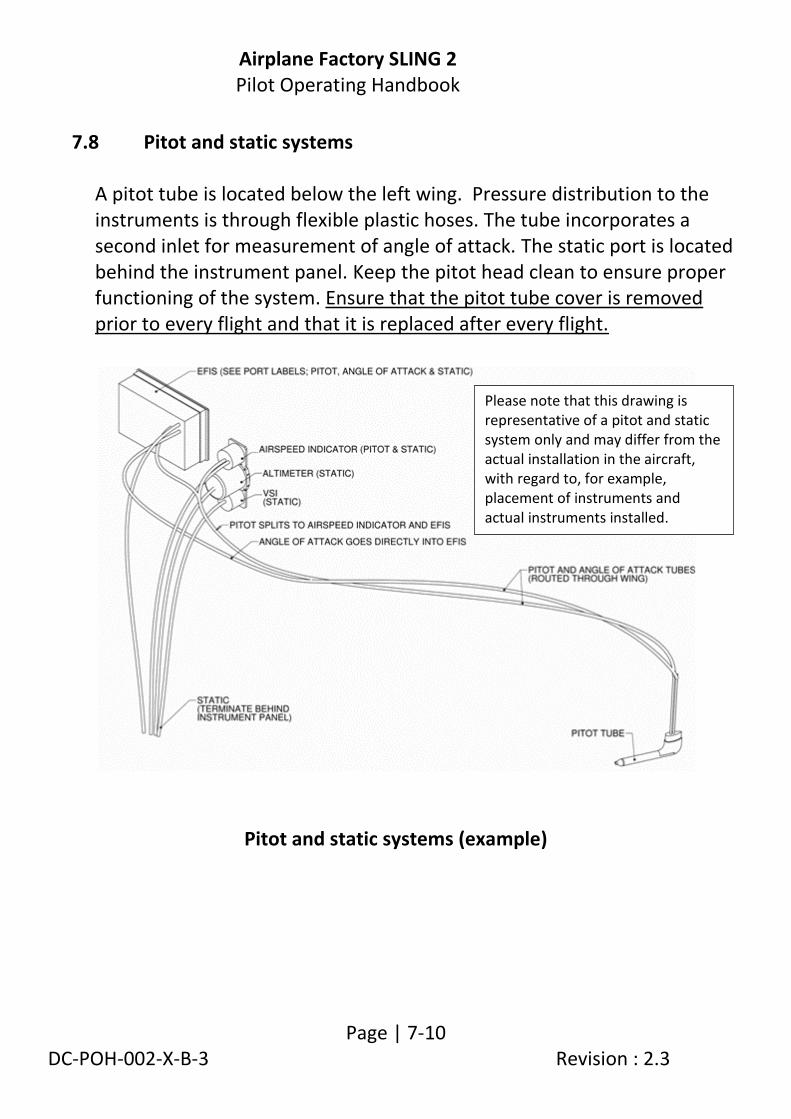
Airplane Factory SLING 2 Pilot Operating Handbook
Page | 7-10 DC-POH-002-X-B-3 Revision : 2.3
7.8 Pitot and static systems A pitot tube is located below the left wing. Pressure distribution to the instruments is through flexible plastic hoses. The tube incorporates a second inlet for measurement of angle of attack. The static port is located behind the instrument panel. Keep the pitot head clean to ensure proper functioning of the system. Ensure that the pitot tube cover is removed prior to every flight and that it is replaced after every flight.
Pitot and static systems (example)
Please note that this drawing is representative of a pitot and static system only and may differ from the actual installation in the aircraft, with regard to, for example, placement of instruments and actual instruments installed.
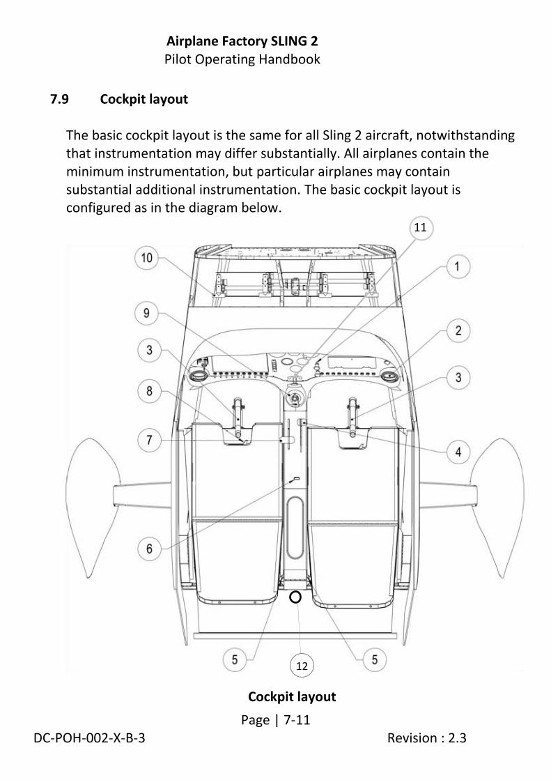
Airplane Factory SLING 2 Pilot Operating Handbook
Page | 7-11 DC-POH-002-X-B-3 Revision : 2.3
7.9 Cockpit layout The basic cockpit layout is the same for all Sling 2 aircraft, notwithstanding that instrumentation may differ substantially. All airplanes contain the minimum instrumentation, but particular airplanes may contain substantial additional instrumentation. The basic cockpit layout is configured as in the diagram below.
Cockpit layout
11
12

Airplane Factory SLING 2 Pilot Operating Handbook
Page | 7-12 DC-POH-002-X-B-3 Revision : 2.3
Cockpit layout key
If differential footbrakes are fitted the hand operated brake actuator on the centre console will be absent. Seats have a slide mechanism with a sideways moving unlocking lever in the centre front of each seat in order to move the seat for comfort and to ensure that the rudder pedals can easily be reached by all pilots. Rudder pedals may also be adjusted through removal of a locking / setting bolt(s). Air vents are located on the lower right and left sides of the instrument panel. Baggage space is immediately behind the seats. A fire-extinguisher is held in place against the front retaining wall of the baggage space. An adjustable red interior cockpit light is positioned behind and between the pilot’s and passenger’s heads, on the rear fuselage front former structure.
1 Instrument panel 7 Throttle
2 Air vent 8 Seat adjustment lever
3 Control stick (PTT on front of stick handle)
9 Fuel selector valve
4 Brake actuator (if footbrake not fitted)
10 Rudder pedals (incorporating brake if differential footbrakes are fitted)
5 Headset plugin sockets 11 Ballistic parachute operating lever
6 Park-brake actuator valve 12 Fire extinguisher

Airplane Factory SLING 2 Pilot Operating Handbook
Page | 7-13 DC-POH-002-X-B-3 Revision : 2.3
7.10 Instruments and Avionics The diagram below represents an instrument panel containing the required minimum instrumentation, together with typical back-up and additional instrumentation supplied with the aircraft. The instrument panel in any particular aircraft may differ from that illustrated in the diagram. It is the responsibility of the pilot to ensure that s/he is familiar with the instrumentation in the aircraft, its layout and its operation.
Standard instrument panel (refer to key on next page)
1
2 4
5 3 6
7
8
9 10 10
11
14 15
16
17
18
19
16 20
21 13
12
22

Airplane Factory SLING 2 Pilot Operating Handbook
Page | 7-14 DC-POH-002-X-B-3 Revision : 2.3
Instrument panel key
Radio and Transponder
Power to the radio and transponder (if fitted) is provided via the main bus and activated via a single switch (for both) labeled AVIONICS, located on the instrument panel. Refer to paragraph 7.17.2.
1 Master switch and starter 13 Cabin heat activator
2 Ignition / “Magneto” switches 14 Cubby hole
3 Charge warning light (914 UL /
912 ULS) 15 12 V Power port / socket
4 MGL EFIS 16 Air vent
5 EFIS accessory warning light 17 Circuit breakers
6 Analogue airspeed indicator 18 Blank off / Ballistic recovery parachute activator handle (if fitted)
7 Analogue magnetic compass 19 Fuel selector valve
8 Analogue altimeter 20 Flap selector
9 MGL V6 COM radio 21 Electrical equipment switches
10 Blank off(s) 22 USB charge port
11 Analogue slip indicator
12 Choke (912 ULS / 914 UL)

Airplane Factory SLING 2 Pilot Operating Handbook
Page | 7-15 DC-POH-002-X-B-3 Revision : 2.3
EFIS system MGL EFIS instruments, including the Voyager, Odyssey, Discovery, Explorer and Challenger, are multifunction “glass cockpit” instruments and typically incorporate a range of different instruments and functions. Although only the minimum specified instrumentation is required (see paragraphs 2.13 and 7.12 of this Pilot Operating Handbook), the full instrumentation provided by the EFIS will typically include:
ASI (IAS as well as TAS and ground speed).
ALT (and typically also height above ground).
VSI.
Compass.
Attitude indicator.
Turn coordinator.
G meter (load factor meter).
Clock, stopwatch and flight time record.
Comprehensive mapping and navigation software and data, including GLS (GPS Landing System) capability.
GPS.
Autopilot (if servos are fitted).
Full engine monitoring and management capacity including :
RPM indicator.
CHT and EGT indicators.
Oil temperature and oil pressure indicators.
Fuel level, fuel flow and fuel pressure indicator.
Hobbs and flight time recorder.
Voltmeter.
Airplane Factory SLING 2 Pilot Operating Handbook
Page | 7-16 DC-POH-002-X-B-3 Revision : 2.3
The EFIS installed in the aircraft is (can be) powered from two separate power sources:
From the main bus, through a circuit breaker and a main selection switch (labeled EFIS) mounted on the instrument panel. Refer to paragraph 7.17.2.
From a battery back-up circuit, via a selection switch (labeled EFIS BKUP) mounted on the instrument panel. Refer to paragraphs 7.17.2 and 7.17.3.
Operational use of the EFIS and EFIS back-up battery system Use and set-up of the EFIS features are extensively described in the documentation supplied with the unit and will not be dealt with in this handbook. Refer to the supplied EFIS documentation. The EFIS is operated during flight with the EFIS back-up battery selection switch (labeled EFIS BKUP) on at all times. This will ensure automatic switch-over of the EFIS to the EFIS back-up battery in the event that power is lost to the main bus. In the event of a charge system failure:
Switch the EFIS main switch off. This will allows the EFIS to switch over to (and be powered from) the EFIS back-up battery supply (provided that the EFIS battery back-up switch is on and the EFIS back-up battery contains adequate charge). Leaving the EFIS main switch on will cause the EFIS to be powered from the main battery (via the main bus), contributing (unnecessarily) to the discharge of the main battery.

Airplane Factory SLING 2 Pilot Operating Handbook
Page | 7-17 DC-POH-002-X-B-3 Revision : 2.3
Set the EFIS screen brightness to the minimum acceptable for readability (to reduce current drain on the back-up battery).
WARNING Users should desist from entering the EFIS setup pages during flight as changes to the setup may result in incorrect readings and/or warnings
resulting in safety degradation.

Airplane Factory SLING 2 Pilot Operating Handbook
Page | 7-18 DC-POH-002-X-B-3 Revision : 2.3
7.11 Flap and elevator trim systems
The aircraft is equipped with electric flaps and an electric elevator trim system. The flap motor is located in the cabin centre console. The two wing flaps are interconnected via a torque tube, which is driven at a single point by the flap motor. Bar a failure in the linkage system, this prevents the flaps from being deployed (driven) to asymmetrical positions. Pilot control of the flap system is via a four-position rotary knob (electronic controller) located on the instrument panel. Refer to paragraphs 7.2 and the instrument panel layout in paragraph 7.10. The flap controller is powered from the main bus. The flap controller in turn powers the flap motor, via a circuit breaker located on the instrument panel (refer to paragraph 7.17.2). The trim motor is located in the port elevator and drives a trim tab (via a pushrod system) located on the elevator trailing edge. Pilot control is via buttons located on the control stick(s). Refer to paragraph 7.2 for button allocation. In 914 UL and 912 ULS equipped aircraft the trim system is powered (via a circuit breaker located on the instrument panel) directly from the charge system output (refer to paragraph 7.17.1) and / or from the battery / main bus (provided the charge relay is energized / not failed). In 912 iS equipped aircraft the trim system is powered from the main bus (refer to the wiring diagrams in the applicable supplement at the end of this manual).
WARNING The flap system becomes non-operational with loss of power to the main bus. The elevator trim remains operational with loss of power to the main bus, provided that the charge system remains operational. On 912 iS equipped aircraft, he elevator trim becomes non-operational with loss of power to the main bus.
Airplane Factory SLING 2 Pilot Operating Handbook
Page | 7-19 DC-POH-002-X-B-3 Revision : 2.3
7.12 Minimum instruments and equipment required for flight: The following minimum instrumentation and equipment is required for day VFR flight:
Altimeter.
Airspeed indicator.
Compass.
Fuel gauges.
Oil pressure indicator.
Oil temperature indicator.
Cylinder head temperature indicator.
Outside air temperature indicator.
Tachometer.
Chronometer.
First aid kit (compliant with national legislation).
Fire extinguisher.
WARNING Notwithstanding that installed equipment may include GPS and other advanced flight and navigational aids, such equipment may not be used as the sole information source for purposes of navigation or flight, except where specifically permitted by law. The aircraft instrumentation is not certified and applicable regulations should be complied with at all times.
NOTE Additional equipment may be required to fulfill
national or specific requirements and may be fitted.

Airplane Factory SLING 2 Pilot Operating Handbook
Page | 7-20 DC-POH-002-X-B-3 Revision : 2.3
7.13 Engine The Rotax 912 ULS engine is a 4-stroke, 4-cylinder, horizontally opposed, spark ignition engine with one central camshaft-push-rod-OHV. The engine features liquid cooled cylinder heads with air cooled cylinders. It utilizes dry sump forced lubrication and has a dual contactless capacitor discharge magneto type ignition system. The engine is fitted with an electric starter, AC generator (alternator) and mechanical fuel pump. A back-up electrical fuel pump is fitted. Propeller drive is via reduction gear with integrated shock absorber. The engine will continue to run after an alternator and / or battery failure. See the manufacturer documentation and applicable supplements to this Pilot operating Handbook for applicable information should the airplane be fitted with a Rotax 914 UL or a Rotax 912 iS engine.
7.14 Cooling system (914 UL / 912 ULS / 912 iS) Cylinders are air cooled. Cylinder heads are liquid cooled via a closed circuit system with an expansion tank. A camshaft driven coolant pump circulates coolant from a radiator through the cylinder heads, then through an expansion bottle and back to the radiator. The expansion tank is closed by a pressure cap. At temperature rise of the coolant an excess pressure valve in the expansion tank opens and coolant flows (via a hose) at atmospheric pressure to an overflow bottle mounted on the firewall. When cooling down the coolant in the overflow bottle is sucked back into the cooling circuit. Refer to the latest revision / edition of the applicable Rotax engine operator and maintenance manuals.
Airplane Factory SLING 2 Pilot Operating Handbook
Page | 7-21 DC-POH-002-X-B-3 Revision : 2.3
Coolant type (912 ULS) For aircraft fitted with the 914 UL or 912 iS engine refer to the applicable supplement at the end of this manual. Either water-free propylene glycol based coolant concentrate or the conventional ethylene glycol based coolant and distilled water mixture (1:1 mix) can be used. Refer to the latest edition / revision of the ROTAX 912 ULS operator / maintenance manuals and to the latest revision of Rotax service instruction SI-912-016. Coolant liquid volume Coolant volume is approximately 2.5 litres (0.66 US gallons).
7.15 Throttle and Choke Refer to the applicable supplement at the end of this manual for additional information regarding the throttle lever on aircraft equipped with the 914 UL engine. Engine power is controlled by means of a hand operated throttle lever situated on the cabin centre console. Refer to paragraph 7.9. Forward movement of the throttle lever increases engine power output and backward movement decreases engine power output.
WARNING Waterless coolant (propylene glycol based) may not be mixed with conventional (ethylene glycol/water) coolant or with additives! Non observance can lead to damage to the cooling system and engine.

Airplane Factory SLING 2 Pilot Operating Handbook
Page | 7-22 DC-POH-002-X-B-3 Revision : 2.3
A choke knob (914 UL and 912 ULS equipped aircraft only) is positioned in the left centre of the instrument panel. Refer to paragraph 7.10. Pulling out the choke knob activates the choke mechanism. Both controls (throttle and choke) are mechanically connected via cables to activators (levers) on the carburetors (914 UL and 912 ULS engines)
7.16 Carburetor pre-heating/anti-ice N/A.
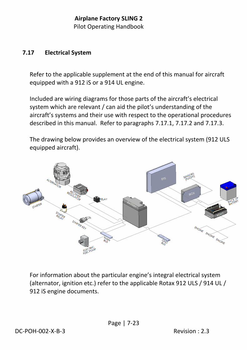
Airplane Factory SLING 2 Pilot Operating Handbook
Page | 7-23 DC-POH-002-X-B-3 Revision : 2.3
7.17 Electrical System
Refer to the applicable supplement at the end of this manual for aircraft equipped with a 912 iS or a 914 UL engine. Included are wiring diagrams for those parts of the aircraft’s electrical system which are relevant / can aid the pilot’s understanding of the aircraft’s systems and their use with respect to the operational procedures described in this manual. Refer to paragraphs 7.17.1, 7.17.2 and 7.17.3. The drawing below provides an overview of the electrical system (912 ULS equipped aircraft).
For information about the particular engine’s integral electrical system (alternator, ignition etc.) refer to the applicable Rotax 912 ULS / 914 UL / 912 iS engine documents.

Airplane Factory SLING 2 Pilot Operating Handbook
Page | 7-24 DC-POH-002-X-B-3 Revision : 2.3
Charge system
For aircraft fitted with the 912 iS engine refer to the applicable supplement at the end of this manual. For aircraft fitted with the 914 UL engine refer to the charge system electrical diagram in the applicable supplement at the end of this manual. The charge system wiring / operation for the 914 UL equipped aircraft is similar to that of the 912 ULS equipped aircraft and the following description applies. Refer to paragraph 7.17.1. The alternating current (AC) output of the engine driven alternator is routed to a rectifier / regulator where it is converted (rectified) and regulated, to provide direct current (DC) output available to the aircraft systems (e.g. to charge the main battery). Charge system output is approximately 13.5 to 14 V DC (from 1000 ±250 rpm and higher). The charge system output is connected to the battery / main bus via a charge relay. Refer to paragraph 7.17.1. The charge relay coil is powered from the main bus (i.e. needs power from the main bus to remain energized / closed): Loss of power to the main bus will result in the charge relay de-energizing and disconnecting the charge system output from the battery / main bus.
Failure (i.e. with the relay contact opening) of the charge relay will disconnect the charge system from the battery / main bus. The main bus / system voltage (indication on EFIS) could show a reduced reading.

Airplane Factory SLING 2 Pilot Operating Handbook
Page | 7-25 DC-POH-002-X-B-3 Revision : 2.3
Alternator failure indication
For alternator failure indication / indicators on 912 iS equipped aircraft fitted with the 912 iS engine please refer to the applicable supplement at the end of this manual. For aircraft fitted with 912 ULS or 914 UL engines the electrical system incorporates an AC generator (alternator) / charge warning light (labeled CHARGE) located on the upper left side of the instrument panel (refer to paragraph 7.10). The light should illuminate if there is an AC generator (alternator) failure. The main bus / system voltage (indication on EFIS) could show a reduced reading. Main battery The 12 V main battery is mounted on the engine side of the firewall. Main bus Refer to the applicable supplement at the end of this manual for aircraft fitted with a 914 UL engine or 912 iS engine. When power to the main bus is unavailable / fails the following equipment becomes non-operational: 1. Auxiliary (electric) fuel pump (912 ULS). 2. Flaps. 3. Autopilot (i.e. the autopilot servos). 4. Propeller (if applicable). 5. Radio. 6. Transponder (if fitted). 7. Cabin light(s). 8. Strobe, navigation and taxi lights. 9 EFIS (unless powered by the EFIS battery back-up circuit)

Airplane Factory SLING 2 Pilot Operating Handbook
Page | 7-26 DC-POH-002-X-B-3 Revision : 2.3
10. The charge relay is de-energised and disconnects the charge system from the battery (912 ULS, 914 UL).
With regard to the above: 1. The EFIS and related equipment (iBOX, RDAC) can be operated via
the EFIS back-up battery circuit, provided that the circuit is switched on and the EFIS back-up battery contains adequate charge.
2. The propeller controller (if applicable) and propeller pitch actuator motor (if applicable) are not powered and the propeller (if applicable) essentially becomes a fixed pitch propeller at the last pitch setting it was commanded to (by the propeller controller).
EFIS back-up battery / circuit The 12 V EFIS back-up battery is mounted on the cabin side of the firewall, under the instrument panel. The EFIS battery back-up circuit can be operated independently from the main bus (i.e. with power to the main bus unavailable). Refer to paragraphs 7.17.2 and 7.17.3. Master and starter switch(es) See the applicable supplement at the end of this manual with regard to the Master / starter switch(es) on 912 iS equipped aircraft. The master switch and starter switch are incorporated into a key switch mounted on the instrument panel. Refer to paragraphs 7.10, 7.17.1 and 7.17.2. The master / starter switch provides the following functionality: • Connects the main bus to the 12 V main battery / charge system. • Activates the starter motor.
Airplane Factory SLING 2 Pilot Operating Handbook
Page | 7-27 DC-POH-002-X-B-3 Revision : 2.3
Ignition Switches Two ignition / magneto switches are located on the left hand side of the instrument panel. Refer to paragraphs 7.10 and 7.17.1. Both ignition / magneto switches should be ON to operate the engine.
Avionics / equipment switches Refer to paragraph 7.17.2. Lever type switches are switched UP for activation (i.e. ON). Optional equipment, switches and / or fuses are subject to change or installed as requested. Refer to the Aircraft Equipment List. Circuit breakers
Circuit breakers are push-to-reset (i.e. push in) for restoring / supplying electrical power to their corresponding electrical circuits. Refer to paragraphs 7.17.1 and 7.17.2. Circuit breakers are located on the instrument panel. Refer to paragraph 7.10.
NOTE The engine (912 ULS / 912 iS / 914 UL) ignition system is independent of the aircraft electrical system (except for starter motor operation) and will operate even with the master switch and / or any circuit breaker(s) off. 914 UL and 912 iS engines require adequate power supply to at least one electrical fuel pump to remain operational (to prevent fuel starvation).

Airplane Factory SLING 2 Pilot Operating Handbook
Page | 7-28 DC-POH-002-X-B-3 Revision : 2.3
7.17.1 Charge system / start system / electric fuel pump wiring diagram (912 ULS)

Airplane Factory SLING 2 Pilot Operating Handbook
Page | 7-29 DC-POH-002-X-B-3 Revision : 2.3
7.17.2 Switches and circuit breakers diagram (912 ULS)

Airplane Factory SLING 2 Pilot Operating Handbook
Page | 7-30 DC-POH-002-X-B-3 Revision : 2.3
7.17.3 EFIS back-up circuit / battery back-up wiring diagram

Airplane Factory SLING 2 Pilot Operating Handbook
Page | 7-31 DC-POH-002-X-B-3 Revision : 2.3
7.18 Propeller
The propeller is a Warp Drive, 72 inch, composite, ground adjustable, 3 blade composite propeller, a Whirlwind, 70 inch, composite, ground adjustable, 3 blade propeller or an Airmaster AP332, 72 inch, composite, electric constant speed, 3 blade propeller.
If the aircraft is fitted with the Airmaster AP332 propeller system refer to the applicable supplement to this Pilot Operating Handbook.
NOTE
For technical data refer to documentation supplied by the propeller manufacturer.

Airplane Factory SLING 2 Pilot Operating Handbook
Page | 7-32 DC-POH-002-X-B-3 Revision : 2.3
7.19 Fuel system
The airplane has a fuel tank located in the inside leading edge of each wing. Each tank is equipped with a vent (underneath wing) and finger screen (on tank outlet). A drain valve is located in the lowest point of the each tank. Tank outlets lead to a fuel selector valve situated on the central console in the cockpit. Fuel return lines return excess fuel supplied by the fuel pump to the fuel tank in use. The system is configured as in the diagram below. Volume of wing tanks: 2 x 75 litres (2 x 19.8 US gal), (73 litres / 19.2 US gal useable per tank).
WARNING The fuel lift pipe in each fuel tank is situated adjacent to the lower inside wall of the tank. The aircraft should at no time be subjected to a sustained side slip towards a near empty fuel tank which is in use (i.e. wing with near empty tank down) as, despite the baffling, this may have the consequence that the fuel runs towards the outer edge of the tank exposing the fuel lift pipe to suck air, thereby starving the engine of fuel leading to engine failure. This poses a particular threat when at low altitude, typically prior to landing.

Airplane Factory SLING 2 Pilot Operating Handbook
Page | 7-33 DC-POH-002-X-B-3 Revision : 2.3
Fuel system (912 ULS)
A Port (left) fuel tank G Barbed T-piece
B Starboard (right) fuel tank H Fuel flow sensor
C Fuel selector (LEFT, RIGHT, OFF) I Port (left) carburettor
D Fuel filter (90° bend) J Fuel pressure sensor
E Electric fuel pump K Starboard (right) carburettor
F Mechanical fuel pump
A B
C
D D
D
E
F
G
H
I J K
FUEL SUPPLY LINE(S) – 8 mm ID FUEL RETURN LINE(S) – 6 mm ID

Airplane Factory SLING 2 Pilot Operating Handbook
Page | 7-34 DC-POH-002-X-B-3 Revision : 2.3
7.20 Lubrication system
For aircraft fitted with the 914 UL or 912 iS engines please refer to the applicable supplements at the end of this manual.
912 ULS The engine is provided with a dry sump forced lubrication system with a camshaft driven main pump with an integrated pressure regulator and oil pressure sensor. The main pump delivers oil from the oil reservoir, through an oil cooler (radiator) and oil filter to points of lubrication. Surplus oil emerging from the points of lubrication gathers at the bottom of the crankcase from where it is forced back to the oil reservoir by piston blow-by gasses. Oil temperature is sensed by a sensor located on the oil pump housing. The lubrication circuit is vented at the oil reservoir. The oil reservior is mounted on the firewall. Refer to the latest revision / edition of the Rotax 912 ULS engine operator and maintenance manuals. The lubrication system volume is approximately 3.5 litres (7.4 pints).
Oil type (912 ULS / 912 iS / 914 UL) Automotive grade API SG (or higher) type oil, preferably synthetic or semi-synthetic.
Refer to the latest revision of the applicable Rotax engine and operator manuals and the latest revision of the applicable Rotax service bulletins.

Airplane Factory SLING 2 Pilot Operating Handbook
Page | 7-35 DC-POH-002-X-B-3 Revision : 2.3
7.21 Autopilot system
The autopilot system is integrated into / with the EFIS unit. Please refer to the latest revisions of the MGL iEFIS Panel Operator Manual and MGL Integrated Autopilot User and Installation Manual for detailed instructions on autopilot operation and functionality. The EFIS / autopilot inputs data from an electronic compass and AHRS, and controls two servos (one for pitch and one for roll) linked to the aircraft control system. Power to the servos is controlled via a switch labeled AUTOPILOT, located on the instrument panel (refer to paragraph 7.17.2). This switch must be on for the autopilot / EFIS outputs to have any effect on aircraft attitude. The autopilot can be engaged in several ways:
The autopilot engage / disengage button on the control stick(s) (refer to paragraph 7.2).
Via the EFIS keypad. The autopilot can be disengaged in several ways: • The autopilot engage / disengage button on the control stick(s) (refer
to paragraph 7.2). • Via the EFIS keypad. • A servo reports (to the autopilot / EFIS) a slipping clutch or torque
overdrive for 1 second, i.e. the pilot overrides the autopilot via mechanical force on the control stick.
• Removing power to the autopilot servos (switching off the AUTOPILOT switch), effectively removing the EFIS / autopilot’s control / actuation of the servo motors.

Airplane Factory SLING 2 Pilot Operating Handbook
Page | 7-36 DC-POH-002-X-B-3 Revision : 2.3
7.22 Position, anti-collision, taxi and landing lights
The aircraft is equipped with a landing light and taxi light in each wing leading edge. Each pair of landing lights is activated by a switch (labeled LAND) on the instrument panel, likewise each pair of taxi lights is activated by a switch (labeled TAXI) on the instrument panel. Combination navigation / position lights (red, green and white) and anti-collision lights (white) are fitted to the wing tips, in the standard configuration (red left, green right). A combination position / anti-collision light (white) is fitted on top of the rudder. The white lights on the wingtips and rudder are dual function lights that can either be on continuously (position light), flash (anti-collision / strobe light) or flash at a higher brightness level superimposed on continuous operation (i.e. combination position and anti-collision / strobe light). Position and anti-collision light function is dependent on switch selection:
SWITCH RED AND GREEN WINGTIP LIGHTS
WHITE WINGTIP LIGHTS
WHITE LIGHT ON RUDDER NAV STROBE
ON OFF On (continuous illumination)
On (continuous illumination)
Off
OFF ON Off On (flashing) On (flashing)
ON ON On (continuous illumination)
On (continuous illumination) and flashing (with higher intensity) superimposed on continuous illumination.
On (continuous illumination) and flashing (with higher intensity) superimposed on continuous illumination.

Airplane Factory SLING 2 Pilot Operating Handbook
Page | 8-1/8-2 DC-POH-002-X-B-3 Revision : 2.3
8. AIRPLANE GROUND HANDLING AND SERVICING
8.1 Introduction .............................................................................................. 8-3
8.2 Servicing fuel, oil and coolant ................................................................... 8-3
8.3 Towing and tie-down / mooring instructions............................................ 8-4
8.4 Parking ...................................................................................................... 8-6
8.5 Jacking ...................................................................................................... 8-6
8.6 Road transport .......................................................................................... 8-7
8.7 Cleaning and care ..................................................................................... 8-7
8.8 Assembly and Disassembly ....................................................................... 8-8
8.9 Aircraft inspection / servicing periods ...................................................... 8-8
8.10 Aircraft modifications and repairs ............................................................ 8-9

Airplane Factory SLING 2 Pilot Operating Handbook
Page | 8-3 DC-POH-002-X-B-3 Revision : 2.3
8.1 Introduction This section contains factory-recommended procedures for proper ground handling and servicing of the aircraft. It also identifies certain inspection and maintenance requirements, which should be followed at all times. Full details for servicing and maintenance appear in the aircraft maintenance manual. This document does not replace the maintenance manual. Reference should always be made to the maintenance manual.
8.2 Servicing fuel, oil and coolant Refer to the appropriate chapters in the Rotax engine maintenance and operator manuals and the Sling 2 Aircraft Maintenance Manual.

Airplane Factory SLING 2 Pilot Operating Handbook
Page | 8-4 DC-POH-002-X-B-3 Revision : 2.3
8.3 Towing and tie-down / mooring instructions
Towing If you wish to move the aircraft on the ground other than under its own power, it is best to pull the aircraft forwards or push it backwards by hand holding one or more propeller blades, close to the spinner. The rear fuselage may be pushed down directly above a bulkhead or the horizontal stabilizer may be pushed down close to the root, directly over the front spar at the point where it attaches to a rib, in order to lift the nose of the aircraft for maneuvering purposes. It is best to press down on both points at once to spread the load. It is also acceptable to push the aircraft carefully backwards by putting pressure on the wing leading edges close to the root, directly on a nose rib, or on the horizontal stabilizer leading edge next to the root over a rib.
CAUTION Avoid excessive pressure on the aircraft airframe - especially at or near control surfaces. The skins are very thin and minimum pressure should be placed on them. Maintain all safety precautions, especially in the propeller area.

Airplane Factory SLING 2 Pilot Operating Handbook
Page | 8-5 DC-POH-002-X-B-3 Revision : 2.3
Mooring The aircraft should be tied down when parked outside a hangar. Mooring is necessary to protect the aircraft against possible damage caused by wind and gusts. For this reason the aircraft is equipped with mooring eyes located on the lower surfaces of the wings and (one) under the tail. Mooring procedure: 1. Verify: Fuel selector shut off, circuit breakers and Master switch
switched off. 2. Verify: Magnetos switched off. 3. Secure the control column(s)(using for example a safety harness). 4. Close air vent. 5. Close and lock canopy. 6. Moor the aircraft to the ground by means of a mooring rope passed
through the mooring eyes located on the lower surfaces of the wings and below the rear fuselage.
NOTE In the case of long term parking, especially during winter, it is recommended to cover the cockpit canopy, or possibly the whole aircraft, by means of a suitable tarpaulin attached to the airframe.

Airplane Factory SLING 2 Pilot Operating Handbook
Page | 8-6 DC-POH-002-X-B-3 Revision : 2.3
8.4 Parking
It is advisable to park the aircraft inside a hangar, or alternatively inside any other suitable space (garage), with stable temperature, good ventilation, low humidity and a dust-free environment. When parking for an extended period, cover the cockpit canopy, and possibly the whole aircraft, by means of a suitable tarpaulin.
8.5 Jacking Since the empty weight of the aircraft is relatively low, two persons are usually able to lift the aircraft. It is possible to lift the aircraft in the following manner:
By pushing the fuselage rear section down above a bulkhead, the fuselage front section may be raised and then supported under the firewall. The same effect can be achieved by pressing down on the horizontal stabilizer as described under Towing.
By lifting the rear fuselage under a bulkhead the rear fuselage may be raised and then supported under that bulkhead. The support should comprise a large, flat surface area to avoid damage to the under-fuselage skin. The wings should also be gently supported to prevent the aircraft from rolling.
To lift a wing, push from underneath the wing only at the main spar area and again using a support that has a large surface area. Do not lift up a wing by handling the wing tip.
A single wheel can be lifted by jacking carefully under the end of the wheel strut.
Airplane Factory SLING 2 Pilot Operating Handbook
Page | 8-7 DC-POH-002-X-B-3 Revision : 2.3
8.6 Road transport
The aircraft may be transported after loading on a suitable trailer. It is necessary to remove the wings before road transport. The aircraft and dismantled wings should be attached securely to protect against possible damage.
8.7 Cleaning and care
Use efficient cleaning detergents to clean the aircraft surface. Oil spots on the aircraft surface (except for the canopy!) may be cleaned with petrol / gasoline. The canopy may only be cleaned by washing it with a sufficient quantity of lukewarm water and an adequate quantity of detergents. Use either a soft, clean cloth sponge or deerskin. Then use suitable polishers to clean the canopy. Upholstery and covers may be removed from the cockpit, brushed and washed in lukewarm water with an adequate quantity of detergents. Dry the upholstery thoroughly before insertion into the cockpit.
CAUTION Never clean the canopy under dry conditions and never use
petrol or chemical solvents.
CAUTION In the case of long term parking, cover the canopy to protect the cockpit interior from direct sunlight.

Airplane Factory SLING 2 Pilot Operating Handbook
Page | 8-8 DC-POH-002-X-B-3 Revision : 2.3
8.8 Assembly and Disassembly
Refer to the aircraft maintenance manual and the aircraft construction manual for assembly and disassembly instructions.
8.9 Aircraft inspection / servicing periods
Periods of checks and contingent maintenance depend upon operating conditions and overall condition of the aircraft. Inspections and servicing should be carried out according to (at least) the following periods: After the first 25 flight hours, thereafter after every 100 flight hours or annually, whichever is
soonest, and as stipulated in the latest revision of the applicable engine manufacturer and propeller manufacturer documentation. Refer to the engine operator’s manual for engine maintenance. Maintain the propeller according to the manual supplied with the unit. Comprehensive aircraft maintenance procedures are set out in the aircraft maintenance manual.

Airplane Factory SLING 2 Pilot Operating Handbook
Page | 8-9 DC-POH-002-X-B-3 Revision : 2.3
8.10 Aircraft modifications and repairs
It is recommended that you contact the aircraft manufacturer prior to making any modifications to the aircraft, to ensure that the airworthiness of the aircraft is not affected. Always use only original spare parts produced by the aircraft (or engine/propeller) manufacturer, as the case may be. If the aircraft weight is affected by a modification, a new mass and balance calculation is necessary. This should be completed comprehensively and new data / figures should be recorded in all relevant documentation.

Airplane Factory SLING 2 Pilot Operating Handbook
Page | 9-1/9-2 DC-POH-002-X-B-3 Revision : 2.3
9. SUPPLEMENTARY INFORMATION
This section contains the appropriate supplements necessary to safely and efficiently operate the aircraft when equipped with various optional systems and equipment not provided with the standard airplane.
List of inserted supplements
Date Suppl. No. Title of inserted supplement
04/06/12 01/2010 Airplanes fitted with a Rotax 914 UL engine
04/06/12 02/2010 Airplanes fitted with a Magnum 601 Ballistic Parachute recovery system
04/06/12 03/2010 Airplanes fitted with an Airmaster AP332 Propeller
19/10/12 04/2012 Airplanes fitted with a Rotax 912 iS engine

Airplane Factory SLING 2 Pilot Operating Handbook
Page | 9-3 DC-POH-002-X-B-3 Revision : 2.3
SUPPLEMENT 01/2010 – AIRPLANES FITTED WITH A ROTAX 914 UL ENGINE This Supplement provides information relating to the operation of a Sling 2 aircraft fitted with a Rotax 914 UL engine. This supplement must be contained in the Pilot Operating Handbook during operation of the airplane. Information contained in this supplement adds to or replaces information from the standard Sling 2 Pilot Operating Handbook in regard only to the specific sections addressed herein. Limitations, procedures and information not addressed in this supplement remain as set out in the Sling 2 Pilot Operating Handbook. Technical data on the Rotax 914 UL engine given in this supplement / manual is provided for information purposes and is subject to latest information / documentation as provided by the engine manufacturer. The Rotax 914 UL engine is a 4-stroke, 4-cylinder, horizontally opposed, turbocharged spark ignition engine with one central camshaft-push-rod-OHV. The engine features liquid cooled cylinder heads with air cooled cylinders. It utilizes dry sump forced lubrication and has a dual contactless capacitor discharge ignition system. The engine is fitted with an electric starter, AC generator (alternator) and an electrical fuel pump. A back-up electrical fuel pump is also fitted. Propeller drive is via reduction gear with integrated shock absorber. The engine will continue to run after an alternator / charge system failure, until the battery voltage is low (approximately 30 minutes if all ancillary equipment is switched off and provided that the battery is fully charged at the time of alternator / charge system failure). The engine will cease running due to fuel starvation (due to electrical pump(s) stopping) when the battery is depleted.

Airplane Factory SLING 2 Pilot Operating Handbook
Page | 9-4 DC-POH-002-X-B-3 Revision : 2.3
ROTAX 914 UL ENGINE OPERATING AND SPEED LIMITS Always refer to latest edition / revision of the engine Operators Manual for latest information regarding operating limitations.
ENGINE START AND OPERATION TEMPERATURE LIMITS (914 UL)
Maximum 50 °C ( 122 °F) (ambient temperature)
Minimum -25 °C ( -13 °F) (oil temperature)
ENGINE LOAD FACTOR (ACCELERATION) LIMITS
Maximum 5 seconds at maximum -0.5 g.

Airplane Factory SLING 2 Pilot Operating Handbook
Page | 9-5 DC-POH-002-X-B-3 Revision : 2.3
ENGINE OPERATING AND SPEED LIMITS
Engine Model: ROTAX 914 UL
Engine Manufacturer: Bombardier-Rotax GmbH
Po
we
r
Maximum take-off
85.76 kW (115 hp) at 5800 rpm, maximum 5 minutes
Maximum continuous
74.6 kW (100 hp) at 5500 rpm
Engi
ne
RP
M
Maximum take-off
5800 rpm (maximum 5 minutes)
Maximum continuous
5500 rpm
Idle 1 500 rpm
Tem
per
atu
re
EGT Maximum 950 °C (1742 °F)
Cyl
ind
er h
ead
Minimum 50 °C (122 °F)
Maximum 135 °C (275 °F).
Normal 90 to 110 °C (194 to 230 °F)
Oil
Minimum 50 °C (122 °F)
Maximum 130 °C (266 °F)
Normal 90 to 110 °C (194 to 230 °F)
Co
ola
nt
Minimum 50 °C (122 °F)
Maximum 120 °C (248 °F)
Normal 80 to 100 °C (175 to 210 °F)

Airplane Factory SLING 2 Pilot Operating Handbook
Page | 9-6 DC-POH-002-X-B-3 Revision : 2.3
Pre
ssu
re
Oil
Minimum 0.8 bar (12 psi) - below 3500 rpm
Maximum 7 bar (102 psi) - permissible for short period on cold engine start
Normal 2 to 5 bar (29 to 73 psi) - above 3500 rpm Fu
el Minimum 1.15 bar (16.7 psi)
Maximum 1.85 bar (26.8 psi)
Man
ifo
ld Maximum
take-off 1.35 bar (19.58 psi) NOTE
Overshoot of manifold pressure is allowed, but has to stabilize within limits within 2 seconds.
Maximum continuous 1.2 bar (17.4 psi)

Airplane Factory SLING 2 Pilot Operating Handbook
Page | 9-7 DC-POH-002-X-B-3 Revision : 2.3
ROTAX 914 UL OPERATING FLUIDS
COOLANT (914 UL)
Grade / type
Water-free propylene glycol based coolant concentrate.
DO NOT MIX THESE TWO TYPES OF COOLANT.
1:1 Ethylene glycol based coolant and distilled water mixture.
Refer to latest revision of Rotax operator / maintenance manuals and latest revision of Rotax service instruction SI-914-019 with regard to selection of operating fluids.
FUEL (914 UL)
Minimum RON 95 / Minimum AKI 91
Grade
MOGAS DIN EN 228 Super, DIN EN 228 Super Plus, ASTM D4814.
AVGAS Leaded AVGAS 100LL ASTM D910.
Unleaded UL91 ASTM D7547.
ENGINE OIL (914 UL)
Grade Automotive grade API SG (or higher) type oil, preferably synthetic or semi-synthetic. When operating on unleaded fuels or MOGAS fully synthetic oil is recommended.
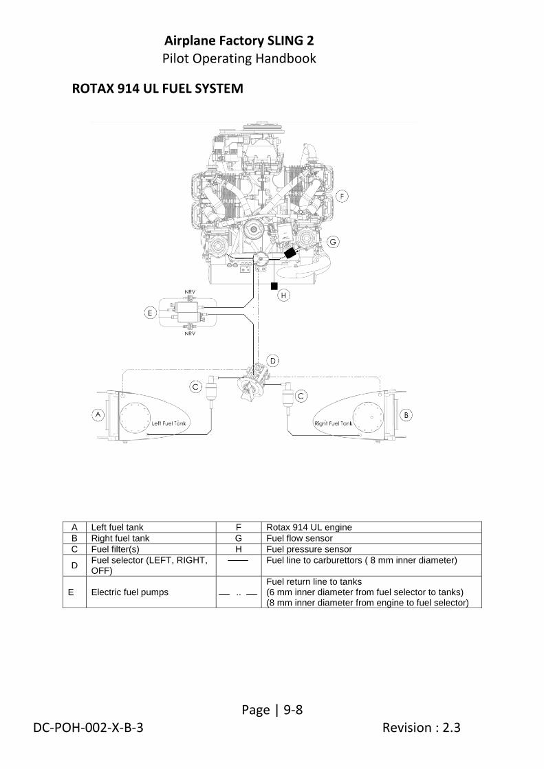
Airplane Factory SLING 2 Pilot Operating Handbook
Page | 9-8 DC-POH-002-X-B-3 Revision : 2.3
ROTAX 914 UL FUEL SYSTEM
A Left fuel tank F Rotax 914 UL engine
B Right fuel tank G Fuel flow sensor
C Fuel filter(s) H Fuel pressure sensor
D Fuel selector (LEFT, RIGHT, OFF)
Fuel line to carburettors ( 8 mm inner diameter)
E Electric fuel pumps .. Fuel return line to tanks (6 mm inner diameter from fuel selector to tanks) (8 mm inner diameter from engine to fuel selector)

Airplane Factory SLING 2 Pilot Operating Handbook
Page | 9-9 DC-POH-002-X-B-3 Revision : 2.3
Fuel feed is through two electric pumps. Each pump has a parallel installed check valve (NRV).
The fuel feed from the fuel pumps enters a fuel pressure controller mounted on the engine, whereafter it splits into two separate branches, one for each carburettor. A fuel pressure sensor is connected to one fuel pipe branch. A fuel flow sensor is connected in the one fuel pipe branch. The sensors are connected to the EFIS via the RDAC unit.
Fuel return lines return excess fuel supplied by the fuel pump(s) to the fuel tank in use. Main fuel pump The main fuel pump is connected to the main bus. The pump cannot be operated when power to the main bus is unavailable. Auxiliary fuel pump The auxiliary fuel pump is connected to the output of the charge system rectifier and via the charge relay to the main battery and main bus (as long as the main bus is powered (i.e. the master switch is on) and the charge relay is energised). If the charge system fails the auxiliary fuel pump can be operated via power from the main bus, provided that the charge relay remains energised / is not failed, the master switch is on and there is no failure of the power supply to the main bus.
If power to the main bus is unavailable, or the charge relay fails, the charge system is disconnected from the main bus and battery. In this case the

Airplane Factory SLING 2 Pilot Operating Handbook
Page | 9-10 DC-POH-002-X-B-3 Revision : 2.3
auxiliary pump can be operated from the output of the charge system / rectifier, provided that the charge system remains operational.
SUPPLEMENTARY INFORMATION - OPERATIONAL USE OF THE FUEL SYSTEM
SUPPLEMENTARY INFORMATION - THROTTLE
The throttle lever incorporates a detent mechanism which stops the lever at the 100% throttle selection position. Moving the throttle lever past the 100% throttle selection requires the manipulation of a detent control / enabling knob located on the throttle lever. Operation of the throttle is related to turbocharger / boost control. Refer to SUPPLEMENTARY INFORMATION – TURBOCHARGER CONTROL UNIT (TCU) in this supplement.
WARNING At least one fuel pump must be operational at all times during flight for the engine to be operational! With no pump operational engine stoppage will occur due to fuel starvation.
THROTTLE LEVER
DETENT KNOB
CENTRE CONSOLE
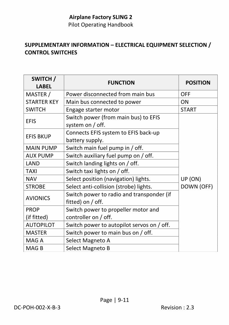
Airplane Factory SLING 2 Pilot Operating Handbook
Page | 9-11 DC-POH-002-X-B-3 Revision : 2.3
SUPPLEMENTARY INFORMATION – ELECTRICAL EQUIPMENT SELECTION / CONTROL SWITCHES
SWITCH / LABEL
FUNCTION POSITION
MASTER / STARTER KEY SWITCH
Power disconnected from main bus OFF
Main bus connected to power ON
Engage starter motor START
EFIS Switch power (from main bus) to EFIS system on / off.
UP (ON) DOWN (OFF)
EFIS BKUP Connects EFIS system to EFIS back-up battery supply.
MAIN PUMP Switch main fuel pump in / off.
AUX PUMP Switch auxiliary fuel pump on / off.
LAND Switch landing lights on / off.
TAXI Switch taxi lights on / off.
NAV Select position (navigation) lights.
STROBE Select anti-collision (strobe) lights.
AVIONICS Switch power to radio and transponder (if fitted) on / off.
PROP (if fitted)
Switch power to propeller motor and controller on / off.
AUTOPILOT Switch power to autopilot servos on / off.
MASTER Switch power to main bus on / off.
MAG A Select Magneto A
MAG B Select Magneto B

Airplane Factory SLING 2 Pilot Operating Handbook
Page | 9-12 DC-POH-002-X-B-3 Revision : 2.3
SUPPLEMENTARY INFORMATION – ELECTRICAL SYSTEM OVERVIEW
The drawing below provides an overview of the electrical system (914 UL equipped aircraft).
SUPPLEMENTARY INFORMATION – MAIN BUS When power to the main bus is unavailable / fails the following equipment, in addition to those listed (and applicable) in paragraph 7.17 under Main bus, becomes non-operational: 1. Main fuel pump. 2. TCU (Turbocharger Control Unit) / waste gate servo. With regard to the above: 1. The auxiliary fuel pump can be operated via the charge system output, provided that the alternator / charge system remains operational. 2. With loss of power to the TCU, the waste gate servo is not powered and will remain in its last commanded position. Boost pressure control is not available and limited flight operation is applicable. Refer to SUPPLEMENTARY INFORMATION – MAIN BUS POWER FAILURE in this supplement.

Airplane Factory SLING 2 Pilot Operating Handbook
Page | 9-13 DC-POH-002-X-B-3 Revision : 2.3
CHARGE AND START SYSTEM WIRING DIAGRAM (914 UL)

Airplane Factory SLING 2 Pilot Operating Handbook
Page | 9-14 DC-POH-002-X-B-3 Revision : 2.3
SWITCHES AND CIRCUIT BREAKERS WIRING DIAGRAM (914 UL)

Airplane Factory SLING 2 Pilot Operating Handbook
Page | 9-15 DC-POH-002-X-B-3 Revision : 2.3
LUBRICATION SYSTEM
The engine is provided with a dry sump forced lubrication system with a camshaft driven main pump with integrated pressure regulator and additional suction pump. The main pump delivers oil from the oil reservoir, through an oil cooler (radiator) and oil filter to points of lubrication. Surplus oil emerging from the points of lubrication gathers at the bottom of the crankcase from where it is forced back to the oil reservoir by a piston blow-by gasses. Oil temperature is sensed by a sensor located on the oil pump housing. The lubrication circuit is vented at the oil reservoir. The oil reservior is located on the firewall. The turbocharger is supplied with oil via a separate oil line from the main pump. Return oil from the turbocharger is collected in a stainless steel sump and is sucked back to the suction pump and then pumped back to the oil reservoir via a return line. Refer to the latest revision / edition of the Rotax 914 UL engine operator and maintenance manuals. The lubrication system volume is approximately 3.5 litres (7.4 pints).

Airplane Factory SLING 2 Pilot Operating Handbook
Page | 9-16 DC-POH-002-X-B-3 Revision : 2.3
SUPPLEMENTARY INFORMATION – TURBOCHARGER CONTROL UNIT (TCU) The applicable sections in the Rotax 914 UL operators manual should be carefully read conjunction with this section. A throttle arm position sensor is mounted on one carburetor. The sensor measures (throttle) position linearly from 0% to 115%, corresponding to engine idle and engine full (100%) power respectively. The TCU (Turbocharger Control Unit) utilizes throttle position in conjunction with aircraft ambient pressure, airbox pressure, engine rpm and airbox temperature to actuate an electronically controlled flap (waste gate) to regulate the speed of the turbocharger / boost pressure in the engine airbox. The TCU starts adding full boost from the 108% throttle position onward. The throttle lever (in cabin) is equipped with a detent at the 100% throttle lever position. A lever on the throttle lever is activated to move the throttle lever past the detent position to allow movement up to the 115% throttle position. Note that 115% throttle position equates to 100% engine power (full take-off power).
Relationship between throttle position and engine power Throttle position Engine power
115% 100% Maximum 5 minutes! (take-off power)
100% 85% Maximum continuous power
NOTE Throttle position from 108% to 110% result in a rapid rise in boost pressure. Avoid constant throttle settings in this range, as it may result in boost pressure control fluctuations (surging). To avoid unstable boost pressure the throttle should be moved smoothly through this range to full power (115% throttle position), or on a power reduction, to maximum continuous power (100% throttle position)

Airplane Factory SLING 2 Pilot Operating Handbook
Page | 9-17 DC-POH-002-X-B-3 Revision : 2.3
The TCU controls two indicator lights mounted on the instrument panel. When supply voltage is supplied to the TCU (master switch is switched on) the TCU is subjected to a self test. Both the BOOST and CAUTION lights should illuminate for 1 to 2 seconds and then turn off. If not, this indicative of a deficiency and the engine should not be taken into operation before the problem has not been identified and rectified.
TCU LIGHT INDICATIONS
POSSIBLE CAUSE Maximum admissible boost pressure exceeded.
Full throttle (115%) operation exceeded maximum duration of 5 minutes.
Sensor failure, wiring failure, TCU failure, possible airbox leak.
BOOST LIGHT INDICATION
Illuminates steadily. Blinks.
CAUTION LIGHT INDICATION
Blinks.
NOTE
Boost pressure will not be reduced automatically. Limited operation as boost control may be unavailable or insufficient.
Boost pressure will not be reduced automatically.
Limited operation as boost control may be unavailable or insufficient.
ACTION
Use throttle lever to reduce boost pressure manually to within operating limits.
Use throttle lever to reduce boost pressure manually to within operating limits (at least maximum continuous values). The BOOST light resets when the throttle setting is below the 108% position for a minimum of 5 minutes.
Use throttle lever to reduce boost pressure manually to within operating limits.
When supply voltage to the TCU fails the waste gate servo (and thus the waste gate flap) will remain in its last commanded position. Boost pressure regulation is not available and limited flight operation is applicable.

Airplane Factory SLING 2 Pilot Operating Handbook
Page | 9-18 DC-POH-002-X-B-3 Revision : 2.3
SUPPLEMENTARY INFORMATION – FUEL CONSUMPTION Take off performance (5 800 RPM) 33.0 l/hr (8.7 US gal/hr). Max continuous power (5 500 RPM) 27.2 l/hr (7.2 US gal/hr). 75% continuous power (cruise) 20.4 l/hr (5.4 US gal/hr). Refer to the fuel consumption graphs and tables in the latest edition / revision of the Rotax 914 UL operator manual for up to date information.
SUPPLEMENTARY INFORMATION – ALTERNATOR / CHARGE SYSTEM FAILURE
Alternator failure is evidenced by the illumination of the (red) alternator / charge warning light. Procedure as in paragraph 3.7.4.
WARNING The engine will continue to run after an alternator / charge system failure, until the battery voltage is low (approximately 30 minutes if all ancillary equipment is switched off and provided that the battery
is fully charged at the time of alternator / charge system failure). The engine will cease running due to fuel starvation (due to stoppage of the fuel pump(s)) when the battery is depleted.
NOTE As per the procedure in paragraph 3.7.4 the auxiliary fuel pump is switched off / verified to be off to conserve battery charge. If required, the auxiliary pump can still be operated from the main bus provided that the master switch is on, there is no failure of power supply to the main bus and the charge relay remains energized / is not failed.

Airplane Factory SLING 2 Pilot Operating Handbook
Page | 9-19 DC-POH-002-X-B-3 Revision : 2.3
SUPPLEMENTARY INFORMATION – EMERGENCY AND ABNORMAL PROCEDURES - ENGINE IRREGULARITIES IN FLIGHT
Turbocharger Control Unit (TCU) lights indication Refer to the table (TCU LIGHT INDICATIONS) relating TCU indicator light mode of indication to probable causes and suggested pilot action in SUPPLEMENTARY INFORMATION – TURBOCHARGER CONTROL UNIT (TCU).
Sudden drop in boost pressure Possible causes may be the turbocharger fracturing or the waste gate not closing. Fractured turbocharger: A loud bang may be heard as a result of and indicating turbocharger fracture. Flight with reduced performance may be possible. Monitor oil pressure. Land as soon as possible. Waste gate not closing: The TCU CAUTION light may be flashing, indicating equipment failure. Limited flight operation (waste gate not responding).
NOTE Refer to the applicable parts (Caution Lamps) of the section on Abnormal Operation in the Rotax 914 UL engine operator manual.

Airplane Factory SLING 2 Pilot Operating Handbook
Page | 9-20 DC-POH-002-X-B-3 Revision : 2.3
Sudden increase in boost pressure A possible cause might be that the waste gate is fully closed. The TCU CAUTION light may be flashing, indicating equipment failure. The BOOST lamp will illuminate steadily when admissible boost pressure is exceeded. Immediately reduce engine speed / rpm until boost pressure is within limits.
SUPPLEMENTARY INFORMATION – MAIN BUS POWER FAILURE
Refer to SUPPLEMENTARY INFORMATION – MAIN BUS in this supplement, for an overview of equipment affected by loss of power to the main bus.
1. Auxiliary fuel pump - on. 2. Use the throttle lever to set / control engine speed and boost
pressure to within operating limits (at least maximum continuous values).
3. Rest of procedure as in paragraph 3.7.5.
NOTE Refer to the applicable parts of the section on Abnormal Operation in the Rotax 914 UL engine operator manual.
CAUTION Power loss to the main bus will result in the main fuel pump stopping and the starter motor becoming unavailable / non-operational. If the engine is allowed to run dry and stop before switching over to the auxiliary fuel pump the engine will have to be restarted via airstream driven propeller rotation (windmilling). The TCU and waste gate servo is not powered and automatic boost pressure control is not available.

Airplane Factory SLING 2 Pilot Operating Handbook
Page | 9-21 DC-POH-002-X-B-3 Revision : 2.3
SUPPLEMENTARY INFORMATION – PERFORMANCE
1. It should be noted that the performance of the aircraft will be altered through use of a 914 UL engine (instead of a 912 ULS engine). In particular: 1.1. Vh will be increased from 116 KIAS to 125 KIAS.
1.2. The aircraft service ceiling will increase to 15 000 ft. 1.3. Take-off run on concrete and grass will be 80 m (262.5 ft) and 100 m
(328.1 ft) respectively. 1.4 Take-off distance (over 15 m (50 ft)) on concrete and grass will be
140 m (459.3 ft) and 160 m (524.9) respectively. 1.5. Rate of climb at 0, 3 000, 6 000 and 9 000 ft ISA will increase to 1 000,
900, 800 and 720 fpm respectively. 1.6. Cruise speeds will not be altered substantially, unless higher power
settings are used.
2. Reference should be made to the latest revision / edition of the Operators Manual of the Rotax 914UL engine for engine operating speeds and limits. Reference should also be made to the Operators Manual of the Rotax 914 UL engine for operational guidelines and instructions. These should be incorporated into the normal or emergency procedures as applicable.
3. Reference should also be made to the latest revision of Rotax service
instruction SI-914-019 with regard to the use and selection of operating fluids (fuel, oil and coolant).

Airplane Factory SLING 2 Pilot Operating Handbook
Page | 9-22 DC-POH-002-X-B-3 Revision : 2.3
SUPPLEMENTARY INFORMATION – ENGINE START
When system voltage is applied (Master switch is switched on) both TCU lights should illuminate for approximately 1 to 2 seconds (TCU self-test) and then extinguish. If not, it indicates a deficiency (refer to Rotax 914 maintenance manuals).
Procedure as in 4.5.2.
WARNING Do not take the engine into
operation before having rectified the cause of the deficiency.

Airplane Factory SLING 2 Pilot Operating Handbook
Page | 9-23 DC-POH-002-X-B-3 Revision : 2.3
SUPPLEMENT 02/2010 – AIRPLANES FITTED WITH A MAGNUM 601 BALLISTIC PARACHUTE This supplement must be contained in the Pilot Operating Handbook during operation of the airplane. Information contained in this Supplement adds to or replaces information from the standards Pilot Operating Handbook in regard only to the specific sections addressed herein. Limitations, procedures and information not addressed in this Supplement remain as set out in the Pilots Operating Handbook. This supplement provides information necessary for the operation of an aircraft fitted with a Magnum 601 ballistic parachute. 1. The Sling 2 is designed specifically for convenient fitment of a
Magnum 601 ballistic parachute recovery system. The system is designed to enable the pilot or passenger to deploy the parachute in case of emergency in such a manner that the aircraft structure is carried under the parachute to the ground, on the basis that the occupants will not be injured and the aircraft structure suffers minimum damage.
2. Use of a ballistic parachute system involves inherent risks and the
system should be properly understood by the pilot prior to use.
BALLISTIC PARACHUTE OPERATIONAL PARAMETERS
PARAMETER Limit speed 320 km.h-1 / 198.84 mph / 172.77 kt.
Deployment time (limit speed) 3 s.
Maximum supported mass 759 kg / 1673.31 lb.
Descend rate (maximum mass) 7 m.s-1.

Airplane Factory SLING 2 Pilot Operating Handbook
Page | 9-24 DC-POH-002-X-B-3 Revision : 2.3
BALLISTIC PARACHUTE DEPLOYMENT 1. Observe ballistic parachute operational parameters. 2. Throttle -idle. 3. Magneto / ignition switches – off. 4. Electric fuel pump(s) - off. 5. Fuel selector lever – off. 6. Deploy the parachute by pulling the T-shaped activation handle
(situated in the centre front) positively. 7. Master and avionics switch - as dictated by radio communication
requirements - off before impact with ground. 8. Other electrical equipment switches - off.
Airplane Factory SLING 2 Pilot Operating Handbook
Page | 9-25 DC-POH-002-X-B-3 Revision : 2.3
SUPPLEMENT 03/2010 – AIRPLANES FITTED WITH AN AIRMASTER AP332 PROPELLER
This supplement must be contained in the Pilot Operating Handbook during operation of the airplane. Information contained in this supplement adds to or replaces information from the standard Pilot Operating Handbook in regard only to the specific sections addressed herein. Limitations, procedures and information not addressed in this supplement remain as set out in the Pilots Operating Handbook. This supplement provides information necessary for the operation of an aircraft fitted with an Airmaster AP 332 variable pitch (constant speed) propeller. Propeller control is via an electronic control unit mounted on the instrument panel. Power to the propeller / propeller controller is provided via the main bus and activated by a switch labeled PROP, located on the instrument panel. Refer to paragraph 7.17.2 (for 912 ULS equipped aircraft) or to the wiring diagrams under SWITCHES AND CIRCUIT breakers in the applicable supplements (for 914 UL and 912 equipped aircraft). 1. Fitment of an Airmaster AP332 propeller to the aircraft will substantially
improve aircraft performance relative to use of a fixed pitch propeller. Generally improvement will be witnessed, where the aircraft is fitted with a Rotax 912 ULS or 912 iS engine, in relation to:
1.1. Vh, which will be increased from 116 KIAS to 120 KIAS. 1.2. The aircraft service ceiling will increase to 14 000 ft.

Airplane Factory SLING 2 Pilot Operating Handbook
Page | 9-26 DC-POH-002-X-B-3 Revision : 2.3
1.3. Take-off distance on concrete and grass will be 100 m (328.1 ft) and 120 m (393.7 ft) respectively.
1.4 Take-off distance (over 15 m (50 ft)) on concrete and grass will be 160 m (524.93 ft) and 180 m (590.55) respectively.
1.5. Rates of climb at 0, 3 000, 6 000 and 9 000 ft ISA will increase to 900, 800, 700 and 600 fpm respectively.
1.6. Cruise speeds will not be altered substantially, unless higher power settings are used.
1.7. Fuel consumption will not be changed unless higher power settings are used.
2. Reference should be made to the Operators Manual for the Airmaster
AP332 Propeller operational guidelines and instructions. These should be incorporated into the normal and emergency procedures for the aircraft as applicable.
SUPPLEMENTARY INFORMATION – PROPELLER CONTROL FAILURE The propeller / propeller controller can fail in a variety of modes / ways.
The pilot(s) should completely familiarize him or herself with the parts of
the Airmaster propeller operator’s manual which deals with Emergency
Operation and Failure Modes.
The following immediate actions should be taken in the event of any
propeller control failure:
1. If required, immediately reduce throttle to avoid exceeding engine
speed limitations.
2. Select manual mode (MAN).
3. If manual control of the propeller pitch is still available:
Set propeller pitch and engine throttle to give desired power
and engine speed combination.

Airplane Factory SLING 2 Pilot Operating Handbook
Page | 9-27 DC-POH-002-X-B-3 Revision : 2.3
4. If manual control of the propeller pitch is not available:
If propeller control failed with the propeller pitch set inside the
flight range, continued flight is possible, but with caution. Use
the engine throttle to control engine / propeller speed, as with
a fixed pitch propeller.
Propeller switch - off.
CAUTION
Selection of too fine a propeller pitch for the engine throttle setting will result in an over-speed situation. Selection of too coarse a propeller pitch may result in the engine being unable to maintain the desired engine speed, even at full throttle.
CAUTION If failure occurred with propeller pitch set at any other pitch than the fine pitch limit, full power from the engine / propeller combination may not be available at low speeds. Consideration should be given to this during approach and landing.

Airplane Factory SLING 2 Pilot Operating Handbook
Page | 9-28 DC-POH-002-X-B-3 Revision : 2.3
SUPPLEMENTARY INFORMATION – PILOT CONTROLS - PROPELLER
PROPELLER CONTROLLER
MANUAL PROPELLER CONTROL SWITCH
PROPELLER CONTROL SELECTOR KNOB (BLUE)
AUTOMATIC / MANUAL SELECTOR SWITCH
FEATHER ENGAGE SWITCH FEATHER INDICATOR LIGHT
COARSE INDICATOR LIGHT
FINE INDICATOR LIGHT
Airplane Factory SLING 2 Pilot Operating Handbook
Page | 9-29 DC-POH-002-X-B-3 Revision : 2.3
Pilot operable controls related to the constant speed propeller system are
the following:
Power switch (labelled PROP), located on the instrument panel. This
switch activates / deactivates the power supply to the propeller
controller unit and to the propeller motor.
Automatic / Manual Selector switch, located on the propeller
controller. This switch selects between propeller automatic (AUTO)
and manual (MAN) control modes:
Automatic mode (AUTO) operation includes constant speed
governing in pre-set (take-off, climb, cruise) and hold modes,
and feathering.
In manual mode (MAN) the Manual Propeller Control switch
provides direct control over propeller pitch, allowing the
propeller to be used as an in-flight adjustable variable pitch
propeller.
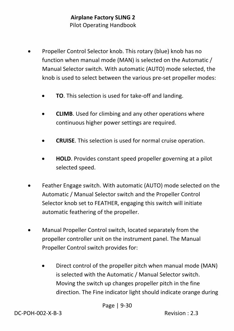
Airplane Factory SLING 2 Pilot Operating Handbook
Page | 9-30 DC-POH-002-X-B-3 Revision : 2.3
Propeller Control Selector knob. This rotary (blue) knob has no
function when manual mode (MAN) is selected on the Automatic /
Manual Selector switch. With automatic (AUTO) mode selected, the
knob is used to select between the various pre-set propeller modes:
TO. This selection is used for take-off and landing.
CLIMB. Used for climbing and any other operations where
continuous higher power settings are required.
CRUISE. This selection is used for normal cruise operation.
HOLD. Provides constant speed propeller governing at a pilot
selected speed.
Feather Engage switch. With automatic (AUTO) mode selected on the
Automatic / Manual Selector switch and the Propeller Control
Selector knob set to FEATHER, engaging this switch will initiate
automatic feathering of the propeller.
Manual Propeller Control switch, located separately from the
propeller controller unit on the instrument panel. The Manual
Propeller Control switch provides for:
Direct control of the propeller pitch when manual mode (MAN)
is selected with the Automatic / Manual Selector switch.
Moving the switch up changes propeller pitch in the fine
direction. The Fine indicator light should indicate orange during

Airplane Factory SLING 2 Pilot Operating Handbook
Page | 9-31 DC-POH-002-X-B-3 Revision : 2.3
the operation. Moving the switch down changes propeller pitch
in the coarse direction. The Coarse indicator light should
indicate orange during the operation.
With the Automatic / Manual Selector switch set to AUTO and
the Propeller Control Selector knob selected to HOLD mode, the
Manual Propeller Control switch is used to set a pilot selected
propeller governing speed.
Actuate the switch to change propeller pitch in the direction
desired. When the desired speed (rpm) is reached, release the
switch. The engine/propeller speed will be governed to that
speed. Finally, set the desired power with the throttle.
NOTE
When power is initially applied to the propeller controller, the speed setting at which the HOLD mode will govern the propeller is set equal to the pre-set CRUISE mode governing speed, until altered by pilot selection.

Airplane Factory SLING 2 Pilot Operating Handbook
Page | 9-32 DC-POH-002-X-B-3 Revision : 2.3
Information conveyed to the pilot(s) by the propeller system is provided by
three lights located on the propeller controller, namely the Coarse indicator
light, Fine indicator light and Feather indicator light. The following table lists
the various propeller status indications provided by said lights in automatic
(AUTO) mode and, where applicable, manual (MAN) mode:
PROPELLER STATUS
INDICATOR LIGHT
FINE COARSE FEATHER
Pitch decreasing Orange
Pitch increasing Orange
Pitch increasing in feather
Orange
No speed signal Orange flashing
Fine pitch limit Green
Coarse pitch limit Green Feather pitch limit Green
Driving at fine pitch limit
Green flashing
Driving at coarse pitch limit
Green flashing
Driving at feather pitch limit
Green flashing
Over-current while pitch decreasing
Red
Over-current while pitch increasing
Red
Over-current while pitch increasing in feather
Red
Open circuit failure Red flashing Red flashing Red flashing
Controller software fault
Rapid red flashing Rapid red flashing Rapid red flashing

Airplane Factory SLING 2 Pilot Operating Handbook
Page | 9-33 DC-POH-002-X-B-3 Revision : 2.3
SUPPLEMENT 04/2012 – AIRPLANES FITTED WITH A ROTAX 912 iS ENGINE This supplement provides information relating to the operation of an aircraft fitted with a Rotax 912 iS engine. This supplement must be contained in the Pilot Operating Handbook during operation of the airplane. Information contained in this Supplement adds to or replaces information from the standard Pilot Operating Handbook in regard only to the specific sections addressed herein. Limitations, procedures and information not addressed in this Supplement remain as set out in the Pilots Operating Handbook. Technical data on the Rotax 912 iS engine given in this supplement / manual is provided for information purposes and is subject to latest information / documentation as provided by the engine manufacturer. The Rotax 912iS is a fuel injected and electronically controlled variant of the Rotax 912 ULS engine. It has the same power rating as the Rotax 912 ULS engine and airplane performance with the two engines is accordingly materially similar, save for fuel economy which, particularly in the cruise, may be materially better in the case of the 912 iS engine. Notwithstanding this, however, there are minor differences between the engines at starting and shutdown and in the case of certain engine related emergency procedures. The instructions in this supplement are the minimum required for the pilot to competently operate the 912 iS engine during normal flight conditions. It is the responsibility of the pilot to fully familiarize himself with the engine Operators Manual supplied by Rotax GmbH, a copy of which is supplied with each aircraft.

Airplane Factory SLING 2 Pilot Operating Handbook
Page | 9-34 DC-POH-002-X-B-3 Revision : 2.3
ROTAX 912 iS ENGINE OPERATING AND SPEED LIMITS Always refer to latest edition / revision of the engine Operators Manual for latest information regarding operating limitations
ENGINE START AND OPERATION TEMPERATURE LIMITS (912 iS)
Maximum (in flight) 60 °C ( 140 °F) (manifold temperature)
Maximum (at start) 50 °C ( 122 °F) (ambient temperature)
Minimum (at start) -20 °C ( -4 °F) (oil temperature)
ENGINE LOAD FACTOR (ACCELERATION) LIMITS
Maximum 5 seconds at maximum -0.5 g.

Airplane Factory SLING 2 Pilot Operating Handbook
Page | 9-35 DC-POH-002-X-B-3 Revision : 2.3
ENGINE OPERATING AND SPEED LIMITS (912 iS)
Engine Model: ROTAX 912 iS
Engine Manufacturer: Bombardier-Rotax GMBH
Po
wer
Max take-off 73.5 kW (98.6 hp) at 5800 rpm
(maximum 5 minutes)
Max continuous 69 kW (92.5 hp)at 5500 rpm
Engine
Max take-off 5800 rpm, maximum 5 minutes
Max continuous 5500 rpm
Idle 1 400 (minimum)
EGT Maximum 950 °C (1742 °F)
Cylinder head
temperature
Minimum N/A
Maximum 150 °C (302 °F)
Normal 75 to 110°C (167 to 230 °F)
Oil temperature
Minimum 50 °C (122 °F)
Maximum 130 °C (266 °F)
Normal 90 to 110 °C (194 to 230 °F)
Oil pressure
Minimum 0.8 bar (12 psi) – below 3500 rpm
Maximum 7 bar (102 psi) – permissible for a short period on cold engine
start
Normal 2 to 5 bar (29 to 73 psi) – above 3500 rpm
Coolant
temperature Maximum 120 °C (248 °F)
Fuel pressure
Minimum 2.8 bar (42 psi)
Maximum 3.2 bar (45 psi)

Airplane Factory SLING 2 Pilot Operating Handbook
Page | 9-36 DC-POH-002-X-B-3 Revision : 2.3
NOTE: AVGAS 100LL places greater stress on the valve seats due to its lead content and forms increased deposits in the combustion chamber and lead sediments in the oil system. Thus it should only be used in case of problems with vapour lock and when other types of gasoline are unavailable.
COOLANT (912 iS)
Grade / type 1:1 Ethylene glycol based coolant and distilled water mixture.
WATER FREE COOLANT NOT PERMITTED FOR USE WITH 912 iS
Refer to latest revision of Rotax operator / maintenance manuals and latest revision of Rotax service instruction SI-912i-001 with regard to selection of operating fluids.
FUEL (912 iS)
Minimum RON 95 / Minimum AKI 91
Grade MOGAS
DIN EN 228 Super, DIN EN 228 Super Plus.
AVGAS Leaded AVGAS 100LL ASTM D910.
ENGINE OIL (912 iS)
Grade Automotive grade API SG (or higher) type oil, preferably synthetic or semi-synthetic. When operating on unleaded fuels or MOGAS fully synthetic oil is recommended.

Airplane Factory SLING 2 Pilot Operating Handbook
Page | 9-37 DC-POH-002-X-B-3 Revision : 2.3
ROTAX 912 iS FUEL SYSTEM
A Port (left) fuel tank F Fuel filter
B Starboard (right) fuel tank G 912 iS engine
C Fuel selector (LEFT, RIGHT, OFF) H Fuel pressure transducer
D Fuel filter (90° bend)
E Fuel pump assembly

Airplane Factory SLING 2 Pilot Operating Handbook
Page | 9-38 DC-POH-002-X-B-3 Revision : 2.3
Fuel feed is through two electric pumps. Each pump has a parallel installed check valve (NRV).
A fuel pressure sensor is connected to the fuel supply line. Fuel pressure is displayed on the EFIS.
Fuel return lines return excess fuel supplied by the fuel pump(s) to the fuel tank in use.
Main and auxiliary fuel pumps
The main and auxiliary fuel pumps are powered via the EMS / ECU. As long as power is available to the EMS / ECU (via Alternator A, Alternator B (in event of Alternator A failure) or via the main battery (the EMS / ECU battery back-up switch is on)) any one, or both of the fuel pumps can be selected / operational, irrespective of the main bus power status. SUPPLEMENTARY INFORMATION – OPERATIONAL USE OF THE FUEL SYSTEM
WARNING At least one fuel pump must be operational at all times during flight for the engine to be operational! With no pump operational engine stoppage will occur due to fuel starvation.
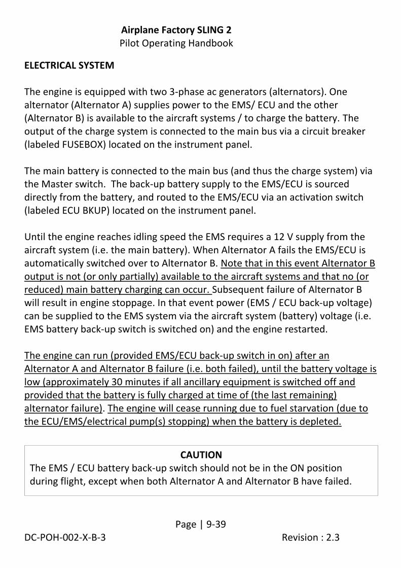
Airplane Factory SLING 2 Pilot Operating Handbook
Page | 9-39 DC-POH-002-X-B-3 Revision : 2.3
ELECTRICAL SYSTEM The engine is equipped with two 3-phase ac generators (alternators). One alternator (Alternator A) supplies power to the EMS/ ECU and the other (Alternator B) is available to the aircraft systems / to charge the battery. The output of the charge system is connected to the main bus via a circuit breaker (labeled FUSEBOX) located on the instrument panel. The main battery is connected to the main bus (and thus the charge system) via the Master switch. The back-up battery supply to the EMS/ECU is sourced directly from the battery, and routed to the EMS/ECU via an activation switch (labeled ECU BKUP) located on the instrument panel. Until the engine reaches idling speed the EMS requires a 12 V supply from the aircraft system (i.e. the main battery). When Alternator A fails the EMS/ECU is automatically switched over to Alternator B. Note that in this event Alternator B output is not (or only partially) available to the aircraft systems and that no (or reduced) main battery charging can occur. Subsequent failure of Alternator B will result in engine stoppage. In that event power (EMS / ECU back-up voltage) can be supplied to the EMS system via the aircraft system (battery) voltage (i.e. EMS battery back-up switch is switched on) and the engine restarted. The engine can run (provided EMS/ECU back-up switch in on) after an Alternator A and Alternator B failure (i.e. both failed), until the battery voltage is low (approximately 30 minutes if all ancillary equipment is switched off and provided that the battery is fully charged at time of (the last remaining) alternator failure). The engine will cease running due to fuel starvation (due to the ECU/EMS/electrical pump(s) stopping) when the battery is depleted.
CAUTION The EMS / ECU battery back-up switch should not be in the ON position during flight, except when both Alternator A and Alternator B have failed.
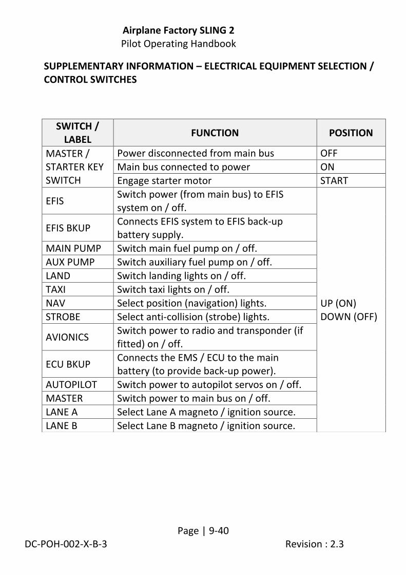
Airplane Factory SLING 2 Pilot Operating Handbook
Page | 9-40 DC-POH-002-X-B-3 Revision : 2.3
SUPPLEMENTARY INFORMATION – ELECTRICAL EQUIPMENT SELECTION / CONTROL SWITCHES
SWITCH / LABEL
FUNCTION POSITION
MASTER / STARTER KEY SWITCH
Power disconnected from main bus OFF
Main bus connected to power ON
Engage starter motor START
EFIS Switch power (from main bus) to EFIS system on / off.
UP (ON) DOWN (OFF)
EFIS BKUP Connects EFIS system to EFIS back-up battery supply.
MAIN PUMP Switch main fuel pump on / off.
AUX PUMP Switch auxiliary fuel pump on / off.
LAND Switch landing lights on / off.
TAXI Switch taxi lights on / off.
NAV Select position (navigation) lights.
STROBE Select anti-collision (strobe) lights.
AVIONICS Switch power to radio and transponder (if fitted) on / off.
ECU BKUP Connects the EMS / ECU to the main battery (to provide back-up power).
AUTOPILOT Switch power to autopilot servos on / off.
MASTER Switch power to main bus on / off.
LANE A Select Lane A magneto / ignition source.
LANE B Select Lane B magneto / ignition source.

Airplane Factory SLING 2 Pilot Operating Handbook
Page | 9-41 DC-POH-002-X-B-3 Revision : 2.3
SUPPLEMENTARY INFORMATION – ELECTRICAL SYSTEM OVERVIEW
The drawing below provides an overview of the electrical system (912 iS equipped aircraft).

Airplane Factory SLING 2 Pilot Operating Handbook
Page | 9-42 DC-POH-002-X-B-3 Revision : 2.3
SUPPLEMENTARY INFORMATION – MASTER AND STARTER SWITCH(ES) The Master / Starter switch in 912 iS equipped aircraft provides the following functionality:
Activates the starter.
Connects / disconnects the main battery to the main bus.
Note that in the case of 912 iS powered aircraft the charge system output is directly connected to the main bus (via a circuit breaker), and not via the master switch as in 912 ULS and 914 UL engined aircraft. This implies that, with the Master switch turned off:
The main bus remains powered, provided that the charge system is operational. In the case where Alternator B is used to power the EMS / ECU (i.e. Alternator A failed), power may not be available the main bus, or reduced power may be available. Also see SUPPLEMENTARY INFORMATION – ALTERNATOR FAILURE and SUPPLEMENTARY INFORMATION – MAIN BUS POWER FAILURE in this supplement.
The battery is disconnected from the main bus and charge system output.

Airplane Factory SLING 2 Pilot Operating Handbook
Page | 9-43 DC-POH-002-X-B-3 Revision : 2.3
ROTAX 912 iS WIRING DIAGRAM

Airplane Factory SLING 2 Pilot Operating Handbook
Page | 9-44 DC-POH-002-X-B-3 Revision : 2.3
ROTAX 912 iS SWITCHES AND CIRCUIT BREAKERS WIRING DIAGRAM

Airplane Factory SLING 2 Pilot Operating Handbook
Page | 9-45 DC-POH-002-X-B-3 Revision : 2.3
ROTAX 912 iS LUBRICATION SYSTEM The engine is provided with a dry sump forced lubrication system with a camshaft driven pump with an integrated pressure regulator. The pump delivers oil from the oil reservoir, through an oil cooler (radiator) and oil filter to points of lubrication. Surplus oil emerging from the points of lubrication gathers at the bottom of the crankcase from where it is forced back to the oil reservoir by piston blow-by gasses. Oil temperature is sensed by a sensor located on the crankcase. The lubrication circuit is vented at the oil reservoir. The oil reservoir is mounted on the firewall. Refer to the latest revision / edition of the Rotax 912 iS engine operator and maintenance manuals. The lubrication system volume is approximately 3.5 litres (7.4 pints).

Airplane Factory SLING 2 Pilot Operating Handbook
Page | 9-46 DC-POH-002-X-B-3 Revision : 2.3
SUPPLEMENTARY INFORMATION – FUEL CONSUMPTION Take off performance (5 800 RPM) 26.1 l/hr (6.9 US gal/hr). Max continuous power (5 500 RPM) 23.6 l/hr (6.2 US gal/hr). 75% continuous power (cruise) 16.5 l/hr (4.35 US gal/hr). Refer to the fuel consumption graphs and tables in the latest edition / revision of the Rotax 912 iS operator manual for up to date information. SUPPLEMENTARY INFORMATION – ALTERNATOR FAILURE ALTERNATOR A FAILURE (ALTERNATOR B OPERATIVE) When Alternator A fails (with alternator B still operative) the EMS/ECU is automatically switched over to Alternator B. Note that in this event Alternator B output is not (or only partially) available to the aircraft systems / to charge the main battery. Procedure as in paragraph 3.7.4. Alternator A failure is evidenced by the steady illumination of the Lane A (red) warning light. The main bus / system voltage (indication on EFIS) could show a reduced reading.
WARNING The engine will continue to run after an Alternator A failure (with Alternator B still operative), as the EMS /ECU is then powered by
Alternator B. However, since no charging of the battery occurs in this circumstance all non-critical electrical equipment should be switched
off to conserve battery charge (as the battery would be needed to supply power to the EMS/ECU/fuel pump(s) if Alternator B
subsequently fails).
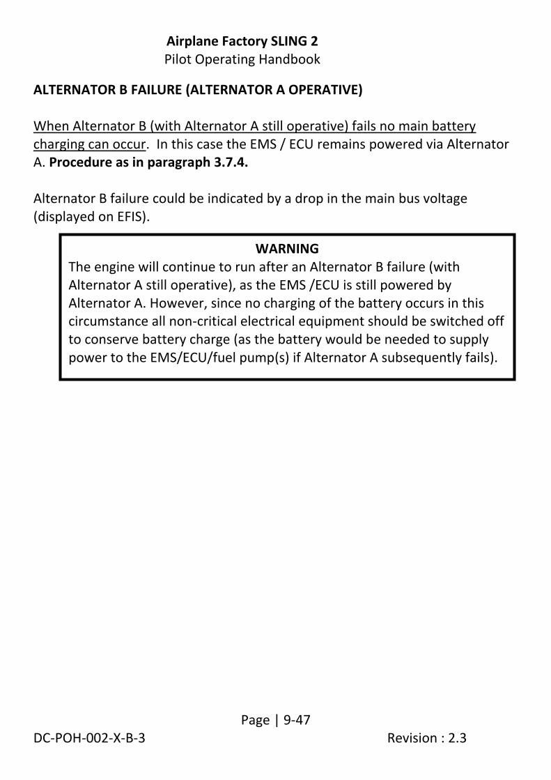
Airplane Factory SLING 2 Pilot Operating Handbook
Page | 9-47 DC-POH-002-X-B-3 Revision : 2.3
ALTERNATOR B FAILURE (ALTERNATOR A OPERATIVE) When Alternator B (with Alternator A still operative) fails no main battery charging can occur. In this case the EMS / ECU remains powered via Alternator A. Procedure as in paragraph 3.7.4. Alternator B failure could be indicated by a drop in the main bus voltage (displayed on EFIS).
WARNING The engine will continue to run after an Alternator B failure (with Alternator A still operative), as the EMS /ECU is still powered by Alternator A. However, since no charging of the battery occurs in this circumstance all non-critical electrical equipment should be switched off to conserve battery charge (as the battery would be needed to supply power to the EMS/ECU/fuel pump(s) if Alternator A subsequently fails).

Airplane Factory SLING 2 Pilot Operating Handbook
Page | 9-48 DC-POH-002-X-B-3 Revision : 2.3
ALTERNATOR A AND ALTERNATOR B FAILURE This will result in engine stoppage (since no power is available to the EMS/ ECU/fuel pump(s)). In this case the EMS / ECU must be powered from the main battery (by switching on the EMS / ECU battery back-up switch) and the engine restarted. 1. EMS battery back-up switch - on. 2. Restart engine. 3. Follow procedure in paragraph 3.7.4. SUPPLEMENTARY INFORMATION – MAIN BUS When power to the main bus is unavailable / fails the following equipment, in addition to those listed (and applicable) in paragraph 7.17 under Main bus, becomes non-operational: 1. Elevator trim.
WARNING The engine can run (with the EMS / ECU powered from the main battery) after an Alternator A and B failure, until the battery voltage is low (approximately 30 minutes, if all ancillary equipment is switched off and provided that the battery is fully charged at the time of (the last remaining) alternator failure). The engine will cease running due to fuel starvation (due to electrical pump(s)/EMS/ECU stopping) when the battery is depleted.

Airplane Factory SLING 2 Pilot Operating Handbook
Page | 9-49 DC-POH-002-X-B-3 Revision : 2.3
SUPPLEMENTARY INFORMATION - ENGINE START
1. Master switch - on. 2. EFIS back-up battery - on, verify EFIS on and back-up battery
voltage. 3. Propeller switch (if applicable) - on. 4. Propeller (if applicable) - AUTO. 5. Magneto / ignition switches (Lane A and B) - on (both). 6. EMS battery back-up switch - on. Once power (EMS battery back-up) is supplied the Lane A and Lane B warning lights should illuminate for approximately 5 seconds and then extinguish. If either or both lights flash or fails to illuminate it is indicative of a deficiency. 7. Fuel selector - select emptiest tank (if not empty). 8. Throttle - set to idle position. 9. Fuel pumps (both) - on. 10. Propeller area - clear of people and obstructions. 11. Starter - activate (for maximum 10 seconds).
WARNING Do not take the engine into
operation before having rectified the cause of the deficiency.

Airplane Factory SLING 2 Pilot Operating Handbook
Page | 9-50 DC-POH-002-X-B-3 Revision : 2.3
Immediately after start-up:
12. Throttle - adjust for smooth running
(approximately 2000 rpm). 13. Oil pressure - increase within 10 seconds. 14. Warm up engine at 2000 rpm for one minute. 15. Increase engine rpm (approximately 3000 rpm) until the main bus /
system voltage indicates 13.8 to 14. 4 V (i.e. Alternator B came online). 16. Reduce engine rpm to 2500 rpm and continue warm up until oil
temperature is 50 °C (122 °F). 17. EMS battery back-up switch - off. At an engine start with low oil temperature continue to watch the oil pressure as it could drop again due to the increased resistance in the suction line. Verify all engine instrument readings.
CAUTION The starter should be activated for a maximum of 10 seconds, followed by a (at least) 2 minute pause to allow the starter to cool. Verify the oil pressure, which should increase within 10 seconds. Increase of engine rpm is only permitted if oil pressure is steady above 3 bar (44 psi). To avoid shock loading, start the engine with the throttle lever set for idling or 5% open at maximum, then wait 3 seconds to reach constant engine speed before accelerating the engine.

Airplane Factory SLING 2 Pilot Operating Handbook
Page | 9-51 DC-POH-002-X-B-3 Revision : 2.3
SUPPLEMENTARY INFORMATION - PRIOR TO TAKE OFF Only one ignition circuit (lane) may be switched on and off at a time. Verify the Lane A and Lane B ignition circuits at 4 000 rpm. No rpm drop should occur when Lane B is switched off. An rpm drop of less than 180 rpm is permissible when Lane A is switched off.