AircraftFire Project Fire risks assessment and increase of ... · Fire risks assessment and...
50
Jean-Michel Most, coordinator CNRS, Pprime, Poitiers, France Contact: [email protected] AircraftFire Project Fire risks assessment and increase of passenger survivability FP7 EASN Project - EU Grant Agreement n° 265612 2011 - 2013 www.aircraftfire.eu
Transcript of AircraftFire Project Fire risks assessment and increase of ... · Fire risks assessment and...

Jean-Michel Most, coordinator CNRS, Pprime, Poitiers, France
Contact: [email protected]
AircraftFire Project Fire risks assessment and increase of passenger survivability
FP7 EASN Project - EU Grant Agreement n° 265612 2011 - 2013
www.aircraftfire.eu
June 19-20th, 2013 FAA Material Working Group, Manchester 2
Summary
1/ Presentation of the AircraftFire project and first results
2/ Fire performance of aeronautical composites • New experimental setup • Fire behaviour of composite materials
June 19-20th, 2013 FAA Material Working Group, Manchester 3
The AircraftFire
Project

Characterisation of the fire performance of composite materials (physical/chemical/thermal flammability and burning
properties) for aircraft design and fire safety analysis (modelling)
Recommendations for efficient industrial technologies
Modelling of the cabin fire growth and passenger evacuation
Development and validation physical models correlated to the evolution of the fire scenarios,
AcF Research Objective
June 19-20th, 2013 FAA Material Working Group, Manchester 4
Evaluation of fire threats and passenger survivability in new generation of aircrafts
Aluminium is substituted by flammable composites for decorative panels, hull, wing, cowling, structure, etc.
The fire threat can significantly increase due to… The flammability of materials in high temperature environment The toxicity of the smokes The total aircraft fuel load
With impact on the fire development and the passenger evacuation
Higher energy supply for avionics and electronics fire risks (ignition,…)
5
CAA, Airbus, EADS
June 19-20th, 2013 FAA Material Working Group, Manchester
The fire threat in new generation of aircrafts
June 19-20th, 2013 FAA Material Working Group, Manchester 6
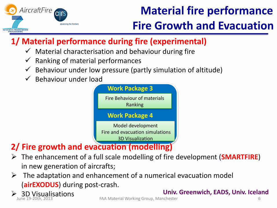
Material fire performance
1/ Material performance during fire (experimental) Material characterisation and behaviour during fire Ranking of material performances Behaviour under low pressure (partly simulation of altitude) Behaviour under load
Univ. Greenwich, EADS, Univ. Iceland
Model development Fire and evacuation simulations
3D Visualization
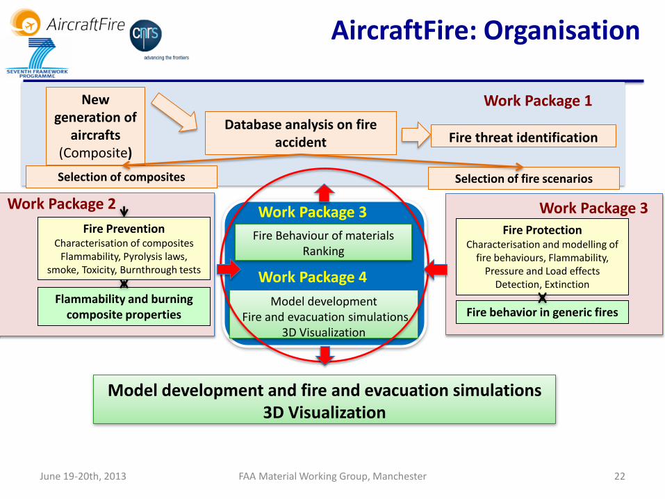
Fire Behaviour of materials Ranking
Work Package 4
Work Package 3
2/ Fire growth and evacuation (modelling) The enhancement of a full scale modelling of fire development (SMARTFIRE)
in new generation of aircrafts; The adaptation and enhancement of a numerical evacuation model
(airEXODUS) during post-crash. 3D Visualisations
Fire Growth and Evacuation
June 19-20th, 2013 FAA Material Working Group, Manchester 7
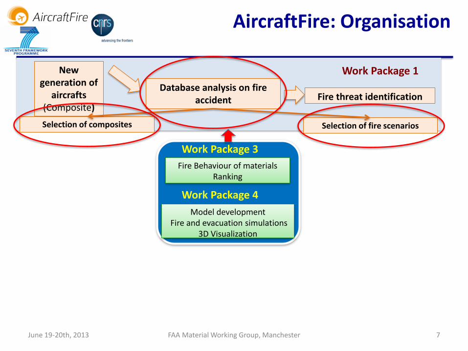
Database analysis on fire accident Fire threat identification
New generation of
aircrafts (Composite)
Selection of fire scenarios Selection of composites
Work Package 1
AircraftFire: Organisation
Model development Fire and evacuation simulations
3D Visualization
Fire Behaviour of materials Ranking
Work Package 4
Work Package 3

Number and Rate of Fire Related Occurrences (UK Fleet) A-High Severity and D Low Severity
June 19-20th, 2013 FAA Material Working Group, Manchester
Fire occurrences by severity grade
CAA, Fraunhofer

Causal factors for Fire occurrences
June 19-20th, 2013 FAA Material Working Group, Manchester
CAA, Fraunhofer

10 June 19-20th, 2013 FAA Material Working Group, Manchester
CAA, Fraunhofer
Distribution of Fire occurrences by phase of flight
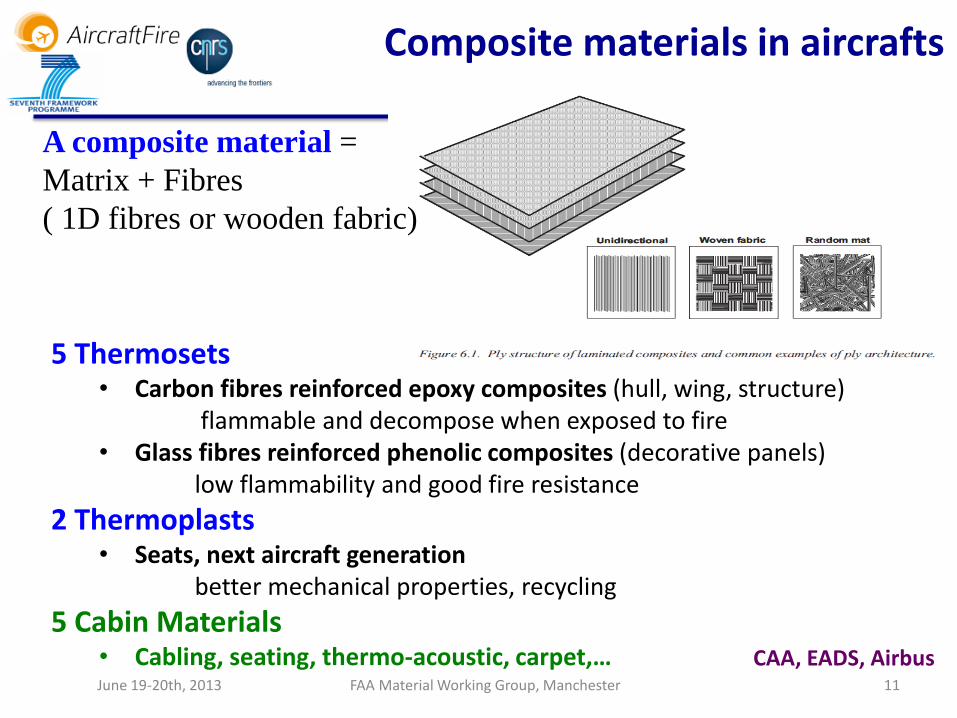
A composite material =
Matrix + Fibres
( 1D fibres or wooden fabric)
Composite materials in aircrafts
5 Thermosets • Carbon fibres reinforced epoxy composites (hull, wing, structure)
flammable and decompose when exposed to fire • Glass fibres reinforced phenolic composites (decorative panels)
low flammability and good fire resistance
2 Thermoplasts • Seats, next aircraft generation
better mechanical properties, recycling
5 Cabin Materials • Cabling, seating, thermo-acoustic, carpet,…
11 June 19-20th, 2013 FAA Material Working Group, Manchester
CAA, EADS, Airbus

June 19-20th, 2013 FAA Material Working Group, Manchester 12
In-flight fire Flammability of materials under load and at low pressure + flame impact
Sustainability of flame in altitude
3 Fire scenarios
Kerosene pool fire modelling
Fire growth and evacuation
o Post-crash fire with cabin integrity
o Post-crash fire with rupture of the cabin or cracks of the skin
Post-crash fire
Hidden zone fire Fire spread, fire propagation

June 19-20th, 2013 FAA Material Working Group, Manchester 13
Database analysis on fire accident Fire threat identification
New generation of
aircrafts (Composite)
Selection of fire scenarios Selection of composites
Work Package 1
Fire Prevention Characterisation of composites
Flammability, Pyrolysis laws, smoke, Toxicity, Burnthrough tests
Flammability and burning composite properties
Work Package 2
AircraftFire: Organisation
Model development Fire and evacuation simulations
3D Visualization
Fire Behaviour of materials Ranking
Work Package 4
Work Package 3

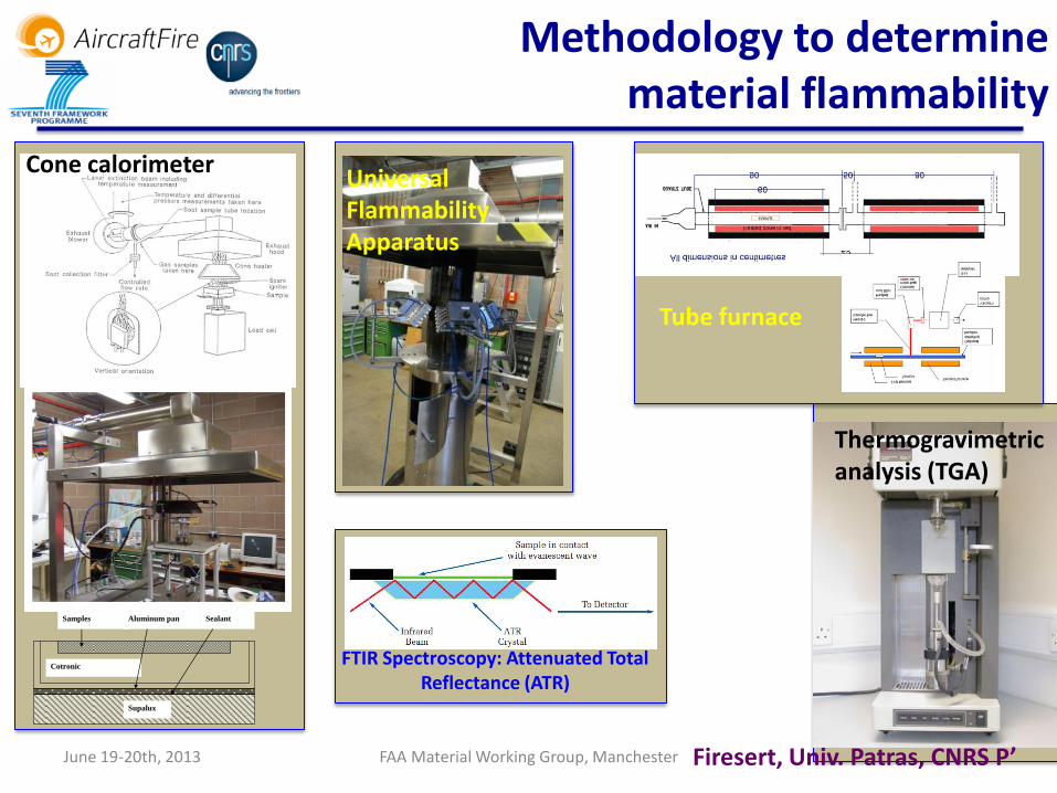
Methodology to determine material flammability properties
Key Flammability properties Techniques
Conductivity, Specific heat, Heat of pyrolysis MDSC
Glass transition temperature, Melting temperature, Heat of melting, Heat of pyrolysis, Specific heat
DSC
Ignition temperature (or the critical heat flux) % of residues, Kinetic parameters for reaction (i.e. activation energy and pre-exponential factor)
TGA
Quantification and history of gases emission TGA - FTIR
Heat of combustion, efficiency of combustion Heat released rate / mass loss rate, CO, CO2, smoke fields Smoke point height
Cone calorimeter
Influence of the ambiant medium, equivalence ratio
Universal flammability apparatus (UFA)
Optical density of smoke Smoke chamber
Firesert, Univ. Patras, CNRS P’, CORIA, Trefle June 19-20th, 2013
June 19-20th, 2013
FTIR Spectroscopy: Attenuated Total Reflectance (ATR)
Universal Flammability Apparatus
Tube furnace
Cotronic
Samples Sealant Aluminum pan
Supalux
Thermogravimetric analysis (TGA)
Cone calorimeter
Firesert, Univ. Patras, CNRS P’ FAA Material Working Group, Manchester
Methodology to determine material flammability

Transmittance:
optical density
Specific optical density:
Extinction coefficient
0
IT
I
1logD
T
s
VD D
AL
TLKext
1ln
1
Objectives: measurement of the optical properties of smokes ===> correlation with their concentration and size
June 19-20th, 2013 FAA Material Working Group, Manchester
Optical density of smoke
CORIA

June 19-20th, 2013 FAA Material Working Group, Manchester 17
dilutor
DMS: particles size
distribution
Smoke sampling and devices for measuring particle parameters
TEOM: Mass
concentration (tapered element oscillating
microbalance)
Optical density of smoke
CORIA

June 19-20th, 2013 FAA Material Working Group, Manchester 18
Database analysis on fire accident Fire threat identification
New generation of
aircrafts (Composite)
Selection of fire scenarios Selection of composites
Work Package 1
Fire Protection Characterisation and modelling of
fire behaviours, Flammability, Pressure and Load effects
Detection, Extinction
Fire behavior in generic fires
Work Package 3 Fire Prevention
Characterisation of composites Flammability, Pyrolysis laws,
smoke, Toxicity, Burnthrough tests
Flammability and burning composite properties
Work Package 2
AircraftFire: Organisation
Model development Fire and evacuation simulations
3D Visualization
Fire Behaviour of materials Ranking
Work Package 4
Work Package 3

June 19-20th, 2013 FAA Material Working Group, Manchester 19
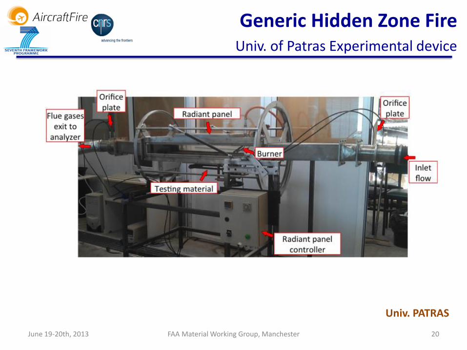
Generic Hidden Zone Fire Experimental and Numerical studies
Orifice plate Thermocouple
Radiant panel
Testing material
Thermocouple Orifice plate
Refractory insulating material
Controlled inlet flow
Flue gases exit to
analyzers Thermocouples (back side of specimen)
Objective: To evaluate the consequences of fire in hidden zones, and its propagation into cabin and cockpit
The effect of under ventilation and of the depletion of oxygen
Smouldering Fire spreading from a local initial fire Presence of unburned pyrolysis gases which may ignite if oxygen
concentration is increased Burnthrough related phenomena
Univ. PATRAS
June 19-20th, 2013 FAA Material Working Group, Manchester 20
Generic Hidden Zone Fire Univ. of Patras Experimental device
Univ. PATRAS
June 19-20th, 2013 FAA Material Working Group, Manchester 21
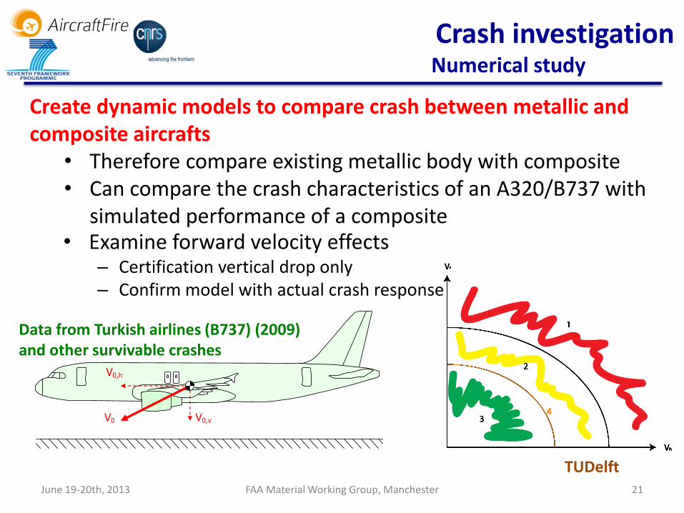
Crash investigation Numerical study
Create dynamic models to compare crash between metallic and composite aircrafts
• Therefore compare existing metallic body with composite • Can compare the crash characteristics of an A320/B737 with
simulated performance of a composite
TUDelft
• Examine forward velocity effects – Certification vertical drop only – Confirm model with actual crash response
Data from Turkish airlines (B737) (2009) and other survivable crashes
V0 V0,v
V0,h
Model development Fire and evacuation simulations
3D Visualization
Fire Behaviour of materials Ranking
Work Package 4
Work Package 3
June 19-20th, 2013 FAA Material Working Group, Manchester 22
Database analysis on fire accident Fire threat identification
New generation of
aircrafts (Composite)
Selection of fire scenarios Selection of composites
Work Package 1
Fire Protection Characterisation and modelling of
fire behaviours, Flammability, Pressure and Load effects
Detection, Extinction
Fire behavior in generic fires
Work Package 3 Fire Prevention
Characterisation of composites Flammability, Pyrolysis laws,
smoke, Toxicity, Burnthrough tests
Flammability and burning composite properties
Work Package 2
AircraftFire: Organisation
Model development and fire and evacuation simulations 3D Visualization
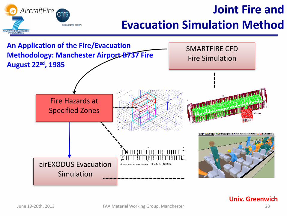
June 19-20th, 2013 FAA Material Working Group, Manchester 23
Univ. Greenwich
SMARTFIRE CFD Fire Simulation
Fire Hazards at Specified Zones
airEXODUS Evacuation Simulation
Joint Fire and Evacuation Simulation Method
An Application of the Fire/Evacuation Methodology: Manchester Airport B737 Fire August 22sd, 1985

June 19-20th, 2013 FAA Material Working Group, Manchester 24
Impact of Exit Opening Times On Evacuation
Base Case S4: R1 and ROW certification times
Univ. Greenwich
Base Case: the reconstruction with
the actual times to open the exits in
the accidentL1(25s), R1 (70s), ROW (45s), R2 (0s)
Scenario 4: 10s for R1 and 12s for
ROW – ideal case, all exits opened
as planned
Could the loss of life have been significantly reduced if the R1 exit was opened earlier? Did the delay in opening the ROW exit impact survivability?

EADS
Smoke visualisation
Smoke visualisation: from left to right the density of smoke increased at same light source parameters

June 19-20th, 2013 FAA Material Working Group, Manchester 26
wind speed : 2 m/s wind speed : 5 m/s wind speed : 10 m/s
Pool size from 10, 20, 30 to 40 m Fuel position : below one engine Burning rate of the liquid fuel : about 6 mm/min Heat release rate : higher than 800 MW Time to steady state : about 30 s
Kerosene pool fire engulfing a full-scale aircraft modelling
Pprime
Temperature, flame spread rate, CO/soot over the composite fuselage

June 19-20th, 2013 FAA Material Working Group, Manchester 27
Experimental and Numerical fields Wind - kerosene pool fire (D=19 m) engulfing a large cylinder object (d=3.7 m)
Temperature and heat flux on the fuselage surface
Exp
eri
me
nta
l dat
a
Suo-Anttila & al (2011), CST 181:1, pp 68-77
1400
1400
1300120011001000
900800700600
500
400
1300 1200 1100
1000
900
800
700600
500
Downwind Position (m)
He
igh
t(m
)
10 15 20 250
1
2
3
4
5
6
24
0
210
180
150
12
0
90
60
30
240
Position on Fuselage (m)
Cir
cu
mfe
ren
tia
lP
os
itio
n
4 6 8 10 12 140
60
120
180
Mo
de
lling
Temperature °C
Heat Flux kW/m2
Pprime

June 19-20th, 2013 FAA Material Working Group, Manchester 28
Database analysis on fire accident Fire threat identification
New generation of
aircrafts (Composite)
Selection of fire scenarios Selection of composites
Work Package 1
Fire Protection Characterisation and modelling of
fire behaviours, Flammability, Pressure and Load effects
Detection, Extinction
Fire behavior in generic fires
Work Package 3 Fire Prevention
Characterisation of composites Flammability, Pyrolysis laws,
smoke, Toxicity, Burnthrough tests
Flammability and burning composite properties
Work Package 2
Database on composites properties
Ranking Increase of passenger survival Fire
prevention and management
Tools and knowledge for aircraft design
Formation
Fire behaviour of composites Data exploitation,
From research to innovation
Work Package 5
AircraftFire: CONCLUSIONS
Airbus, EADS, CNRS Fraunhofer Univ. Iceland
Model development Fire and evacuation simulations
3D Visualization
Fire Behaviour of materials Ranking
Work Package 4
Work Package 3

June 19-20th, 2013 FAA Material Working Group, Manchester 29
Pprime
In-house
Burnthrough test
Facility

June 19-20th, 2013 FAA Material Working Group, Manchester 30
Material qualification Mimic of Passed/Failed standard tests
Flux 182kW/m2 (fuselage, wing, structure)
Flux 106 kW/m2 (engine) Gas Temperature: 1100°C
The burnthrough test: Time of burnthrough Efficiency of the barrier to the flame
Gas burner
Kerosene burner
FAA test AC 20-135
Photos from FAA website
June 19-20th, 2013 FAA Material Working Group, Manchester 31
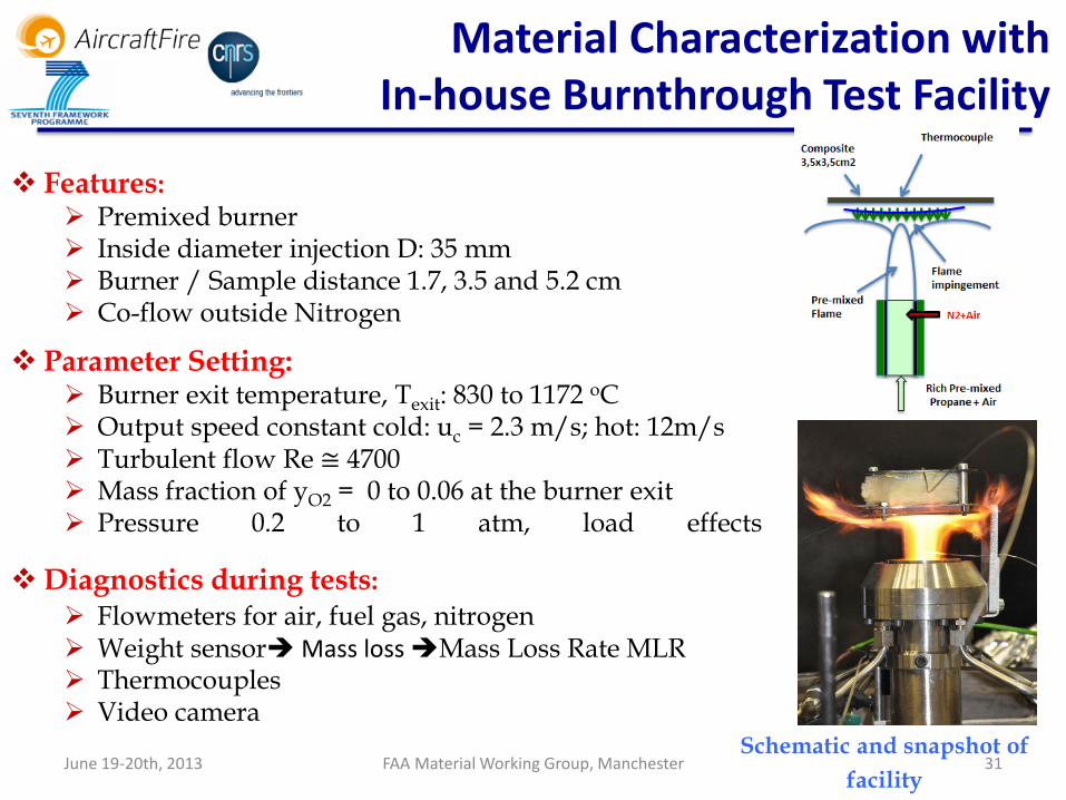
Material Characterization with In-house Burnthrough Test Facility
Features: Premixed burner Inside diameter injection D: 35 mm Burner / Sample distance 1.7, 3.5 and 5.2 cm Co-flow outside Nitrogen
Parameter Setting: Burner exit temperature, Texit: 830 to 1172 oC Output speed constant cold: uc = 2.3 m/s; hot: 12m/s Turbulent flow Re ≅ 4700 Mass fraction of yO2 = 0 to 0.06 at the burner exit Pressure 0.2 to 1 atm, load effects
Schematic and snapshot of
facility
Diagnostics during tests:
Flowmeters for air, fuel gas, nitrogen Weight sensor Mass loss Mass Loss Rate MLR Thermocouples Video camera

June 19-20th, 2013 32 32
Heat Flux calibration Radiometer – Tube calorimeter
32
Propylene
Propane
Radiometer
Thermocouple
Burner
PIV
Cold Flow u = 3 m/s Hot Flow u = 12 m/s
FAA Material Working Group, Manchester

BT= 140s
June 19-20th, 2013 FAA Material Working Group, Manchester 33
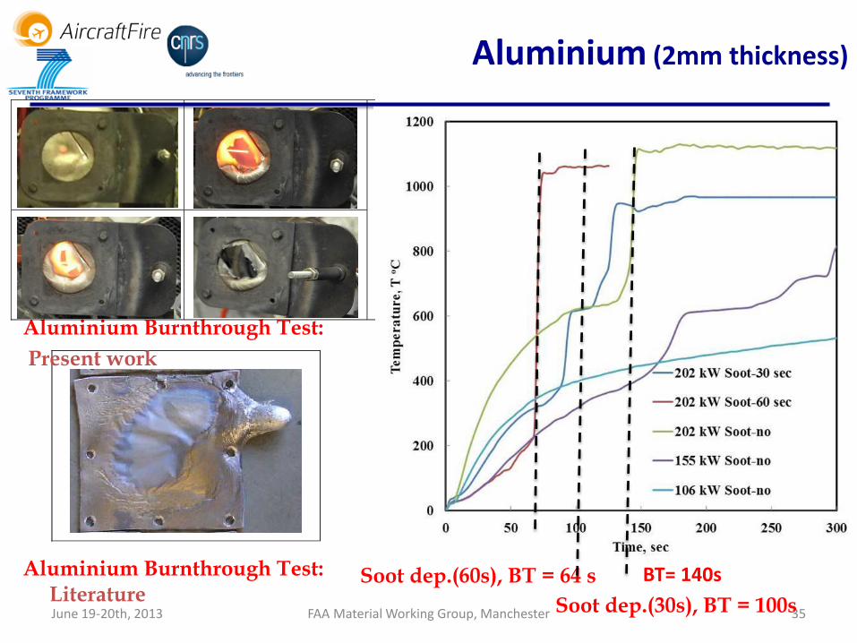
Aluminium (2mm thickness)
Aluminium Burnthrough Test:
Present work
Aluminium Burnthrough Test: Literature

June 19-20th, 2013 FAA Material Working Group, Manchester 34
Complete burnthrough data for aluminium b=2 mm
Aluminium: Burnthrough Data
Authors Burnthro
ugh time,
tb sec
Sample
surface
and Test
No,
Device of tests
Webster, H (1994),
FAA
30 Full scale fire
test on aircraft
fuselage
Marker (1996),
FAA
60 Full scale
burnthrough
test
Dodd (1996), CAA 223 clean Burnthrough
furnace test 43 sooted
Marker (1996),
FAA
120 1 Standard
burnthrough
test
55 2
Petit (1998), CEAT 30 1 Small burner
burnthrough
test
40 2
Lopez (2000) 163 Small scale pan
fire
Dimitris et al.
(2011)
173 Large In-house
gas burner
Present work
(Pprime)
289 1 Small In-house
gas burner 130 2
89 3
64 4
Web
ster (
19
94
) :
Fu
ll s
ca
le f
use
lag
e
test
Ma
rk
er (
19
96
) :
Fu
ll s
ca
le B
T
Do
dd
(1
99
6)
: F
urn
ace t
est
Ma
rk
er
(19
96
) :
Sta
nd
ard
Test
Peti
t (
19
96)
: S
ma
ll b
urn
er T
est
Lo
pez
(20
00)
: S
ma
ll p
an
fir
e T
est
Dim
itris
(2
01
1)
: L
arg
e g
as
bu
rn
er
Test
Present work
15
5 k
W/m
2
20
2 k
W/m
2
20
2 k
W/m
2 :
So
ot
30
sec
20
2 k
W/m
2 :
So
ot
60
sec
BT= 140s
June 19-20th, 2013 FAA Material Working Group, Manchester 35
Aluminium (2mm thickness)
Aluminium Burnthrough Test:
Present work
Aluminium Burnthrough Test: Literature
Soot dep.(60s), BT = 64 s
Soot dep.(30s), BT = 100s
June 19-20th, 2013 FAA Material Working Group, Manchester 36
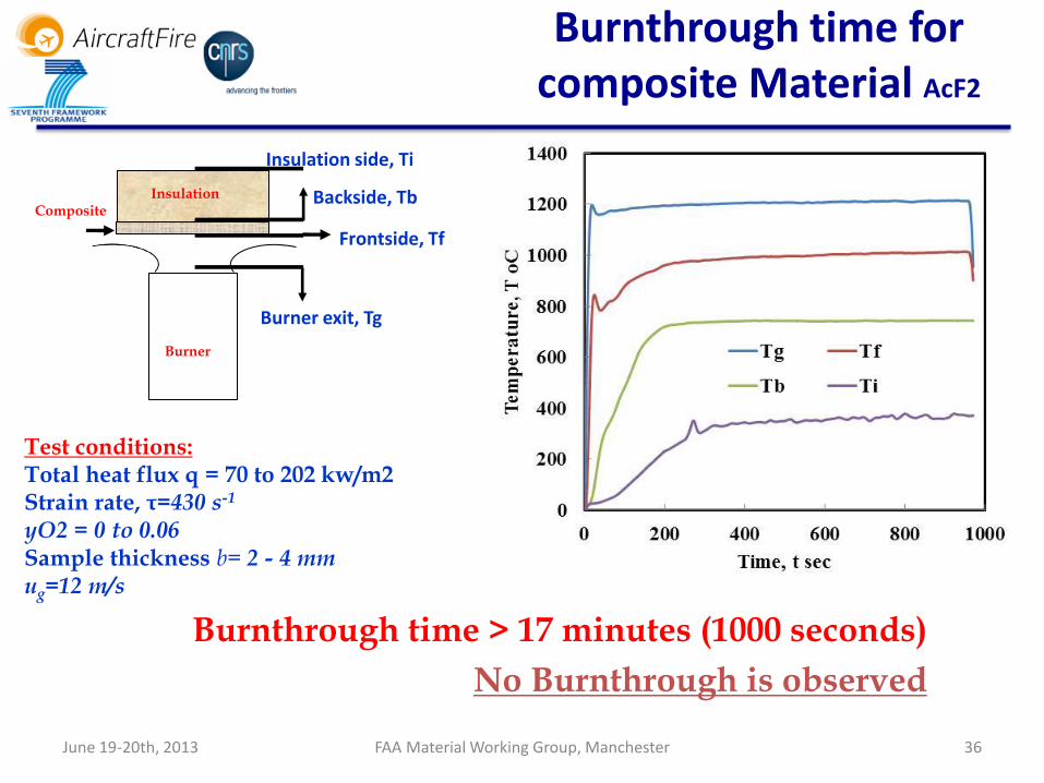
Burner exit, Tg
Frontside, Tf
Backside, Tb
Insulation side, Ti
Burner
Insulation Composite
Test conditions: Total heat flux q = 70 to 202 kw/m2 Strain rate, τ=430 s-1
yO2 = 0 to 0.06 Sample thickness b= 2 - 4 mm ug=12 m/s
Burnthrough time > 17 minutes (1000 seconds)
No Burnthrough is observed
Burnthrough time for composite Material AcF2
June 19-20th, 2013 FAA Material Working Group, Manchester 37
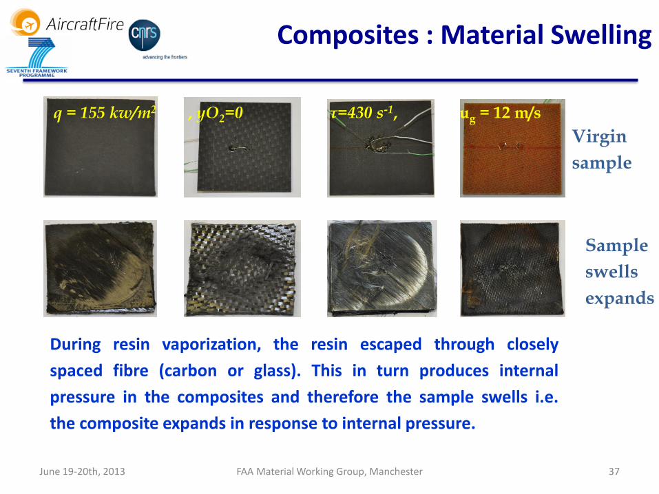
Composites : Material Swelling
During resin vaporization, the resin escaped through closely
spaced fibre (carbon or glass). This in turn produces internal
pressure in the composites and therefore the sample swells i.e.
the composite expands in response to internal pressure.
Virgin
sample
Sample
swells
expands
q = 155 kw/m2 , yO2=0 τ=430 s-1, ug = 12 m/s
June 19-20th, 2013 FAA Material Working Group, Manchester 38
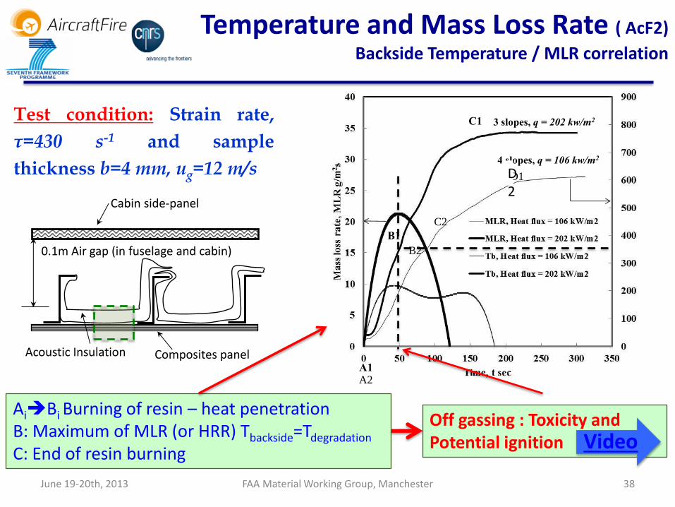
Temperature and Mass Loss Rate ( AcF2)
Backside Temperature / MLR correlation
Test condition: Strain rate,
τ=430 s-1 and sample
thickness b=4 mm, ug=12 m/s
Acoustic Insulation Composites panel
Cabin side-panel
0.1m Air gap (in fuselage and cabin)
A1A2
B1
C2
B2
C1
D1
3 slopes, q = 202 kw/m2
4 slopes, q = 106 kw/m2
AiBi Burning of resin – heat penetration B: Maximum of MLR (or HRR) Tbackside=Tdegradation
C: End of resin burning
D2
Off gassing : Toxicity and Potential ignition Video
June 19-20th, 2013 FAA Material Working Group, Manchester 39
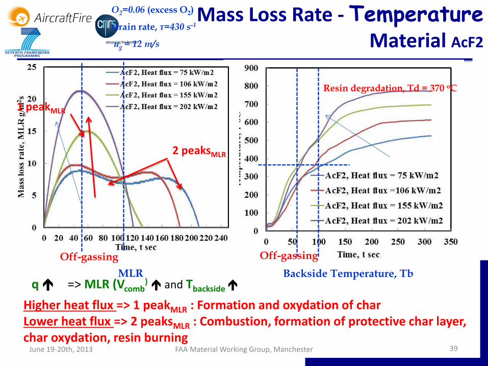
Mass Loss Rate - Temperature Material AcF2
O2=0.06 (excess O2)
strain rate, τ=430 s-1
ug = 12 m/s
Backside Temperature, Tb
Off-gassing
Resin degradation, Td = 370 oC
MLR
Off-gassing
1 peakMLR
2 peaksMLR
q => MLR (Vcomb) and Tbackside
Higher heat flux => 1 peakMLR : Formation and oxydation of char Lower heat flux => 2 peaksMLR : Combustion, formation of protective char layer, char oxydation, resin burning
June 19-20th, 2013 FAA Material Working Group, Manchester 40
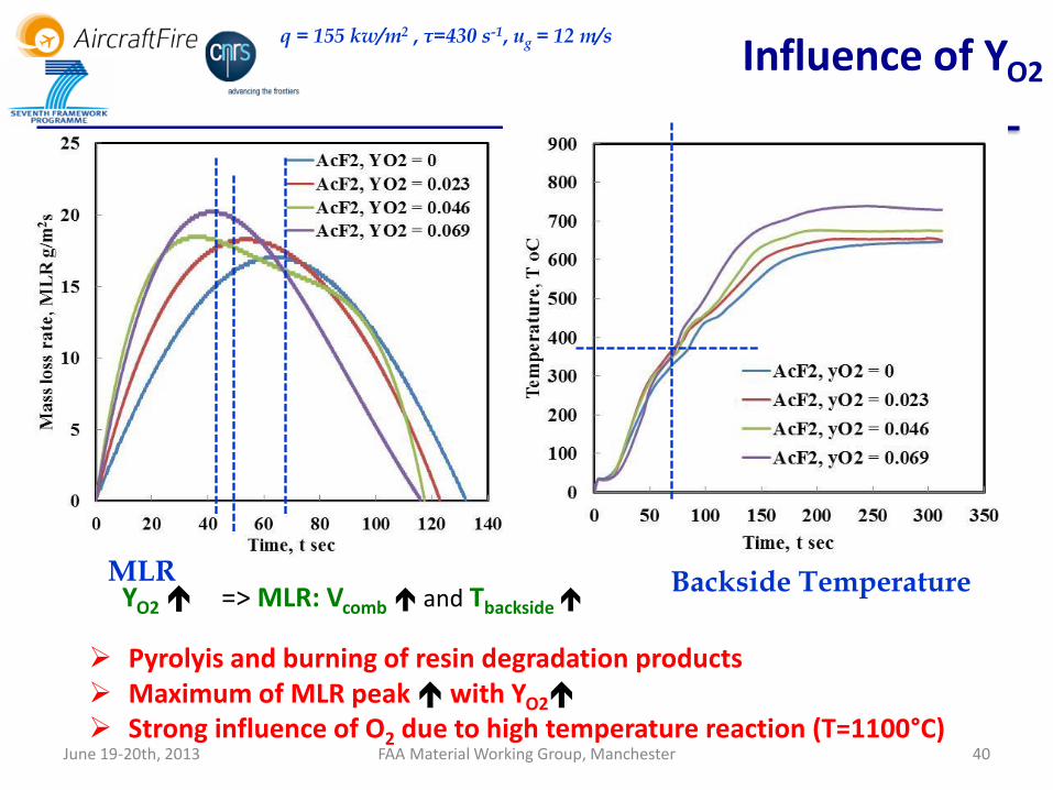
Backside Temperature MLR
q = 155 kw/m2 , τ=430 s-1, ug = 12 m/s
Influence of YO2
YO2 => MLR: Vcomb and Tbackside
Pyrolyis and burning of resin degradation products Maximum of MLR peak with YO2
Strong influence of O2 due to high temperature reaction (T=1100°C)

June 19-20th, 2013 FAA Material Working Group, Manchester 41
MLR
Influence of material Thickness b
b => MLR: Vcomb ≈ and Tbackside
b=2mm: 2 peaksMLR (low heat flux) e=4mm: 1 peakMLR
Vcomb, b=2mm ≈ Vcomb, b=4mm (thermal effect)
b => Fire Resistance b=2mm : insulation effect on backside with higher dT/dt
Backside Temperature
q = 155 kw/m2
τ=430 s-1
ug = 12 m/s
June 19-20th, 2013 FAA Material Working Group, Manchester 42
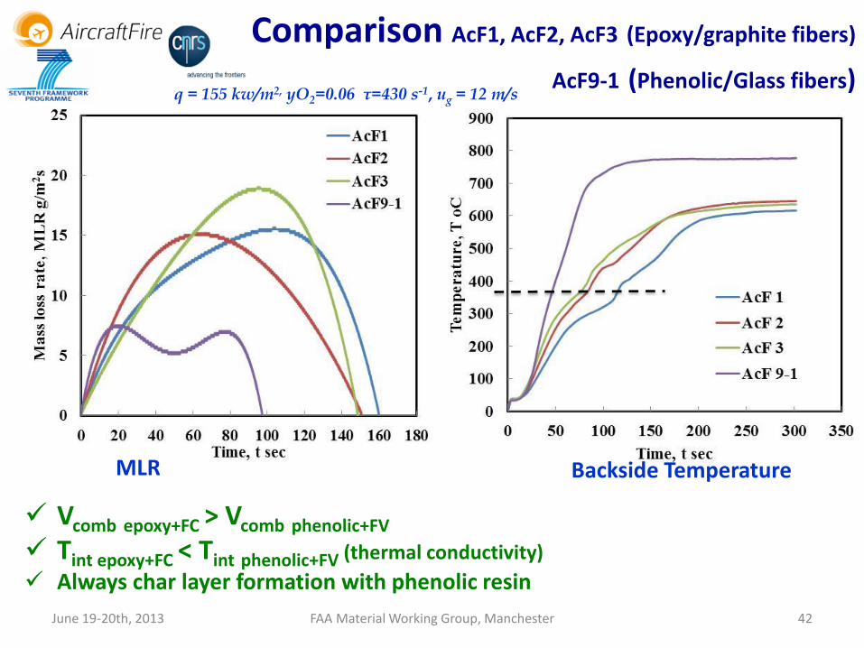
Comparison AcF1, AcF2, AcF3 (Epoxy/graphite fibers)
AcF9-1 (Phenolic/Glass fibers)
Backside Temperature MLR
q = 155 kw/m2, yO2=0.06 τ=430 s-1, ug = 12 m/s
Vcomb epoxy+FC > Vcomb phenolic+FV Tint epoxy+FC < Tint phenolic+FV (thermal conductivity)
Always char layer formation with phenolic resin
June 19-20th, 2013 FAA Material Working Group, Manchester 43
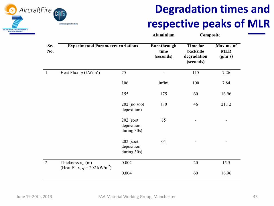
Degradation times and respective peaks of MLR

June 19-20th, 2013 FAA Material Working Group, Manchester 44
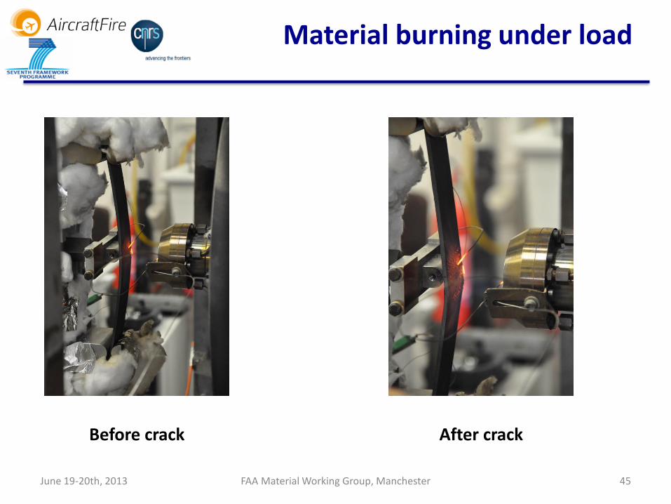
Material burning under load
Experiment consists of exposing a sample of composite material to a flow of hot gases generated in the burner while applying a bending load
Contraint in fibers exposed to the flame: Tension stress
Contraint in fibers exposed to the flame: Compression stress
Experimental device
June 19-20th, 2013 FAA Material Working Group, Manchester 45
Before crack After crack
Material burning under load

June 19-20th, 2013 FAA Material Working Group, Manchester 46
Sample after testing
Material burning under load
0
5
10
15
20
25
30
35
40
45
0 50 100 150 200 250
t (s
)
HF (kW/m²)
Failure time, AcF2
t 30 4mm
t lin 4mm
t 30 2mm
t lin 2mm
AcF2 Failure Time (HF) b=2mm (Deflection 30mm) b=4mm (Deflection 15mm)
Burner – composite distance: 5.2cm

June 19-20th, 2013 FAA Material Working Group, Manchester 47
Conclusion
Burnthrough standard test burner • Parameters:
• Temperature and heat flux at the material location, imposed geometry
• Type and Material thickness • Main Result: burnthrough time (passed/failed tests)
Burnthrough AircraftFire burner • Parameters:
• Temperature and heat flux at the material location • Material thickness, YO2, τ, Pressure, Load, etc.
• Results: • Burnthrough time! • Burning rate (combustion regimes (char), effects of additives) • Measurements of interface temperatures (heat flux inside the composite)
Fast and low cost tests for materials (composites)

June 19-20th, 2013 FAA Material Working Group, Manchester 48
Conclusion
No burnthrough observed for composites in the studied conditions (up to 15minutes)
• Heat flux: 182kW/m2 Gas Temperature: 1100°C
Main results Vcombustion mass loss of 24-30% in mass of the sample resin
Peak 1 of MLR Pyrolysis and
combustion
Peaks 2 of MLR Protective char formation Char combustion
End of resin combustion (less than 3 minutes)
Fibres oxidation Fire propagation in the cabin consequences Aluminium : Time for Burnthrough Composite: Time for beginning of backside off gassing Tback=Tdeg
Potential diffusion of toxic gases in the cabin Ignition of fuel degradation products

June 19-20th, 2013 FAA Material Working Group, Manchester 49
AircraftFire partners
Organisations Responsible E-mail
CNRS Pprime Jean-Michel Most [email protected]
CNRS Trefle Jean-Christophe Batsale [email protected]
Fraunhofer Goert Luedtke [email protected]
Airbus Stephane Pugliese [email protected]
CAA Graham Greene [email protected]
EADS Mario Cappitelli [email protected]
Univ. Iceland Bjorn Karlsson [email protected]
Univ. Greenwich Ed. Galea [email protected]
FIRESERT Michael Ddelichatsios [email protected]
CORIA INSA Alexis Coppalle [email protected]
Univ. Patras Thrassos Panidis [email protected]
Univ. Edinburgh Jose Torero [email protected]
TUDelft Rene C. Alderliesten [email protected]
June 19-20th, 2013 FAA Material Working Group, Manchester 50
AircraftFire
THANK YOU FOR YOUR ATTENTION