
Aircraft & System Performance and functional requirements · D57 - Aircraft & System Performance...
55
Aircraft & System Performance and functional requirements Document information Project Title Airborne Initial 4D Trajectory Management Project Number 09.01._ Project Manager AIRBUS Deliverable Name Aircraft & System Performance and functional requirements Deliverable ID D57 Edition 01.01.00 Template Version 03.00.00 Task contributors AIRBUS Abstract This document is the “Aircraft & System Performance and Functional Requirements” related to Initial 4D function. The objective of this document is to: - Capture the on-board operational needs to perform Initial 4D operations - Provide on-board operational and functional requirements required to perform Initial 4D operations according to SESAR 1 concept description in P05.06.01. This document (D57) is an update of D06 (Aircraft & System Performance and functional requirements) integrating the results from last validation exercises (e.g. EXE-05.03-VP- 708, EXE-05.03-VP-805) and the last versions of OSED and SPR documents in the frame of SESAR 1. It also encompasses formal traceability with OSED and SPR requirements. It covers requirements for mainline, regional, rotorcraft and military aircraft operations. This document is part of Release 5 SESAR Solution 6.
Transcript of Aircraft & System Performance and functional requirements · D57 - Aircraft & System Performance...
Aircraft & System Performance and functional requirements
Document information
Project Title Airborne Initial 4D Trajectory Management
Project Number 09.01._
Project Manager AIRBUS
Deliverable Name Aircraft & System Performance and functional requirements
Deliverable ID D57
Edition 01.01.00
Template Version 03.00.00
Task contributors
AIRBUS
Abstract This document is the “Aircraft & System Performance and Functional Requirements” related to Initial 4D function. The objective of this document is to:
- Capture the on-board operational needs to perform Initial 4D operations - Provide on-board operational and functional requirements required to perform
Initial 4D operations according to SESAR 1 concept description in P05.06.01. This document (D57) is an update of D06 (Aircraft & System Performance and functional requirements) integrating the results from last validation exercises (e.g. EXE-05.03-VP-708, EXE-05.03-VP-805) and the last versions of OSED and SPR documents in the frame of SESAR 1. It also encompasses formal traceability with OSED and SPR requirements. It covers requirements for mainline, regional, rotorcraft and military aircraft operations. This document is part of Release 5 SESAR Solution 6.
Project Number 09.01._ Edition 01.01.00 D57 - Aircraft & System Performance and functional requirements
2 of 55 ©SESAR JOINT UNDERTAKING, 2016. Created by Airbus for the SESAR Joint Undertaking within the frame of the SESAR Programme co-financed by the EU and EUROCONTROL. Reprint with approval of publisher and the source properly acknowledged
Authoring & Approval Prepared By - Authors of the document. Name & Company Position & Title Date Sophie LAPERCHE (Alten SO for Airbus) 09.01 contributor 23/09/2016 Isabelle LAVIELLE (Airbus) 09.01 contributor 23/09/2016
Reviewed By - Reviewers internal to the project. Name & Company Position & Title Date Lucille REVERTGAT (Airbus) 09.01 project leader 23/09/2016 Erwan PARICAUD (Honeywell) 09.01 contributor 23/09/2016 Caroline BIARNES (Thales) 09.01 contributor 23/09/2016 David DE SMEDT (Eurocontrol) 09.01 contributor 23/09/2016 Massimo CORAZZA (Alenia) 09.01 contributor 23/09/2016 Raphaël PASCAL (Airbus) WP09 project leader 23/09/2016
Reviewed By - Other SESAR projects, Airspace Users, staff association, military, Industrial Support, other organisations. Name & Company Position & Title Date Fabio MANGIARACINA (SICTA) 04.10 project leader 12/07/2016 François GUYOT (Airbus Helicopter) 04.10 contributor 13/07/2016 Massimo CORAZZA (Leonardo) 09.03 project leader 14/07/2016 Luigi BRUCCULERI (SICTA) 04.03 project leader 07/07/2016 Stefan KITS (Combitech) 05.06.01 project leader 07/07/2016 Ibrahim BAYRAKTUTA (Eurocontrol) 10.02.01 project leader - Pascal ROHAULT (Thales) 10.07.01 project leader - Charlotte CHAMBELIN (DGAC) 04.02 project leader 13/07/2016 Richard PUGH (NATS) 05.02 project leader - Didier DELIBES (Airbus) 09.49 project leader 28/06/2016 Pablo SANCHEZ ESCALONILLA (ENAIRE) 05.03 project leader - Richard LATCHFORD (NATS) 04.05 project leader - David BOLE-RICHARD (DGAC) 04.07.02 project leader - Francesco NACCHIA (SICTA) 05.05.01 project leader -
Approved for submission to the SJU By - Representatives of the company involved in the project. Name & Company Position & Title Date Raphaël PASCAL (Airbus) WP09 project leader 23/09/2016 Erwan PARICAUD (Honeywell) 09.01 contributor 23/09/2016 Dorothee DE VILLELE (Honeywell) 09.01 contributor 23/09/2016 Caroline BIARNES (Thales) 09.01 contributor 23/09/2016 David DE SMEDT (Eurocontrol) 09.01 contributor 23/09/2016
Massimo CORAZZA (Leonardo) 09.01 contributor / 09.03 project manager 23/09/2016
Fabio MANGIARACINA (Sicta) 04.10 project manager 23/09/2016 Rejected By - Representatives of the company involved in the project. Name & Company Position & Title Date

Project Number 09.01._ Edition 01.01.00 D57 - Aircraft & System Performance and functional requirements
3 of 55 ©SESAR JOINT UNDERTAKING, 2016. Created by Airbus for the SESAR Joint Undertaking within the frame of the SESAR Programme co-financed by the EU and EUROCONTROL. Reprint with approval of publisher and the source properly acknowledged
Rational for rejection
Document History Edition Date Status Author Justification
01.00.00 24/06/2016 Isabelle Lavielle New Document
01.01.00 23/09/2016 Isabelle Lavielle New issue to take into account SJU comments.
Intellectual Property Rights (foreground) This deliverable consists of SJU foreground.
Project Number 09.01._ Edition 01.01.00 D57 - Aircraft & System Performance and functional requirements
4 of 55 ©SESAR JOINT UNDERTAKING, 2016. Created by Airbus for the SESAR Joint Undertaking within the frame of the SESAR Programme co-financed by the EU and EUROCONTROL. Reprint with approval of publisher and the source properly acknowledged
Table of Contents EXECUTIVE SUMMARY .................................................................................................................................... 5
1 INTRODUCTION .......................................................................................................................................... 6 1.1 PURPOSE OF THE DOCUMENT ............................................................................................................... 6 1.2 INTENDED READERSHIP......................................................................................................................... 6 1.3 INPUTS FROM OTHER PROJECTS ........................................................................................................... 7 1.4 STRUCTURE OF THE DOCUMENT ........................................................................................................... 7 1.5 REQUIREMENTS DEFINITIONS – GENERAL GUIDANCE ......................................................................... 8 1.6 FUNCTIONAL BLOCK PURPOSE ............................................................................................................. 8 1.7 FUNCTIONAL BLOCK OVERVIEW ........................................................................................................... 8 1.8 GLOSSARY OF TERMS ........................................................................................................................... 8 1.9 ACRONYMS AND TERMINOLOGY ........................................................................................................... 9
2 GENERAL FUNCTIONAL BLOCK DESCRIPTION ............................................................................ 12
2.1 CONTEXT ............................................................................................................................................. 12 2.2 FUNCTIONAL BLOCK MODES AND STATES.......................................................................................... 13 2.3 MAJOR FUNCTIONAL BLOCK CAPABILITIES ......................................................................................... 13 2.4 USER CHARACTERISTICS .................................................................................................................... 13 2.5 OPERATIONAL SCENARIOS ................................................................................................................. 13 2.6 FUNCTIONAL ........................................................................................................................................ 15
2.6.1 Functional decomposition ........................................................................................................... 15 2.6.2 Functional analysis ...................................................................................................................... 16
2.7 SERVICE VIEW .................................................................................................................................... 19
3 FUNCTIONAL BLOCK FUNCTIONAL AND NON-FUNCTIONAL REQUIREMENTS .................. 20
3.1 INITIAL 4D FUNCTIONAL REQUIREMENTS ........................................................................................... 20 3.1.1 Navigation Requirements ............................................................................................................ 20 3.1.2 Communication Requirements ................................................................................................... 30 3.1.3 HMI Requirements ....................................................................................................................... 37 3.1.4 Military Functional Requirements .............................................................................................. 40
3.2 ROTORCRAFT INITIAL 4D OPERATIONAL REQUIREMENTS ........... ERROR! BOOKMARK NOT DEFINED. 3.3 ADAPTABILITY...................................................................................................................................... 45 3.4 PERFORMANCE CHARACTERISTICS .................................................................................................... 46 3.5 SAFETY & SECURITY ........................................................................................................................... 46
3.5.1 Security Requirements ................................................................................................................ 46 3.5.2 Safety Requirements ................................................................................................................... 46
3.6 MAINTAINABILITY ................................................................................................................................. 48 3.7 RELIABILITY ......................................................................................................................................... 48 3.8 FUNCTIONAL BLOCK INTERNAL DATA REQUIREMENTS ...................................................................... 48 3.9 DESIGN AND CONSTRUCTION CONSTRAINTS ..................................................................................... 48 3.10 FUNCTIONAL BLOCK INTERFACE REQUIREMENTS .............................................................................. 48
4 ASSUMPTIONS ......................................................................................................................................... 49
5 REFERENCES ........................................................................................................................................... 50 5.1 USE OF COPYRIGHT / PATENT MATERIAL /CLASSIFIED MATERIAL ....................................................... 50
5.1.1 Classified Material ........................................................................................................................ 50
List of figures Figure 1: Initial 4D operation typical scenario ....................................................................................... 13
Project Number 09.01._ Edition 01.01.00 D57 - Aircraft & System Performance and functional requirements
5 of 55 ©SESAR JOINT UNDERTAKING, 2016. Created by Airbus for the SESAR Joint Undertaking within the frame of the SESAR Programme co-financed by the EU and EUROCONTROL. Reprint with approval of publisher and the source properly acknowledged
Executive summary This document is the “Aircraft & System Performance and Functional Requirements” related to Initial 4D function.
The airborne implementation of the aircraft capability to comply with a time constraint issued by the ATC within the required accuracy and reliability is called “Initial 4D function” in this document. It also encompasses the communication capabilities necessary for the 3D trajectory synchronization (air/ground communication process ensuring that ground and airborne systems share the same view of the intended aircraft trajectory) as well as the manoeuvre negotiation and agreement between the ATC and the flight crew.
The concept of operation in which the Initial 4D function has been developed and validated in the frame of P09.01 activities during SESAR 1 is further described based on P05.06.01 results.
When applicable, P09.01 Initial 4D functional requirements are linked to rotorcraft (based on P04.10 Initial 4D concept) and military aircraft (based on P09.03 concept). A section dedicated to military aircraft functional requirements (see 3.1.4) is available and an annex (see appendix A) is dedicated to rotorcraft operational aspects which include operational requirements defined by P04.10 project and not contained in any OSED document.
The applicability to rotorcraft (P04.10 project) may be further refined, due to the fact the P04.10 i4D evaluation results are not conclusive enough to allow drawing clearly the needed conclusions. Further evaluations of the applicability to the rotorcraft users are recommended in order to fully explore the concept.
This document is part of Release 5 SESAR Solution 6.
Project Number 09.01._ Edition 01.01.00 D57 - Aircraft & System Performance and functional requirements
6 of 55 ©SESAR JOINT UNDERTAKING, 2016. Created by Airbus for the SESAR Joint Undertaking within the frame of the SESAR Programme co-financed by the EU and EUROCONTROL. Reprint with approval of publisher and the source properly acknowledged
1 Introduction
1.1 Purpose of the document The aim of this document is to gather and describe the high level functional requirements for airborne implementation of Initial 4D function, based on operational hypothesis.
The reference document used to build this functional description was the P05.06.01 (Ground & Airborne Capabilities to Implement Sequence) Step 1 OSED [12]. It has been updated (previous version was D06) to take into account 05.06.01 Step 1 OSED [12] and SPR [13] Final which have been updated following last Initial 4D validation exercises.
Some elements have been updated with the last version of OSED, SPR and Interop performed in the frame of 05.06.01 SESAR project.
This document applies to mainline, regional, military aircraft and rotorcraft.
Functional Requirements related to the on-board implementation of Initial 4D function are identified using the following format: REQ-<project number>-TS-<issue>.<number>.
The field <project number> identifies to which type of aircraft the REQ applies: - 09.01: Mainline, Regional aircraft, also used in the REQ identifier when the requirement is
applicable to the other types of aircraft considered in this document: military and/or rotorcraft. The applicability is then identified in the field “<ALLOCATED TO>, <Project>” of each requirement.
- 09.03: Military aircraft, used when the considered requirement is applicable only to military. The field <issue> identifies in which issue of the document the REQ has been either introduced or modified:
- 0: stands for requirements identified in previous FRD version (D06) with FRD-INITIAL4D-<number> or NEW-INITIAL4D-<number>.
- 1: stands for the requirements modified in this issue (01.01.00) of the FRD (D57). - 2: stands for the requirements introduced in this issue (01.01.00) of the FRD (D57).
The field <number> identifies each REQ with a unique reference. When the REQ was introduced in the previous version of this document, the REQ number has been kept to ensure its traceability.
In appendix A, complementary operational requirements dedicated to rotorcraft Initial 4D operations are identified using the following format: REQ-04.10-GEN1-i4DT.<number> where the field <number> identifies each REQ with a unique reference.
Requirements on the airborne implementation of Initial 4D are identified by the use of “shall” or “should”:
- “Shall” indicates mandatory requirements
- “Should” indicates optional requirements i.e. these requirements may not be implemented but if they are implemented, they have to be implemented as described in the operational requirement.
1.2 Intended readership The intended audience is:
o 09.03 project
o 09.05 project
o 09.49 project
o 04.10 project
o 04.02 project
o 05.06.01 project
o 05.02 project
Project Number 09.01._ Edition 01.01.00 D57 - Aircraft & System Performance and functional requirements
7 of 55 ©SESAR JOINT UNDERTAKING, 2016. Created by Airbus for the SESAR Joint Undertaking within the frame of the SESAR Programme co-financed by the EU and EUROCONTROL. Reprint with approval of publisher and the source properly acknowledged
o 05.03 project
o OFA03.02.01
o OFA04.01.02
o ENB03.01.01 TMF
o B4.3 project
1.3 Inputs from other projects This document takes into account the following documents issued in the context of SESAR projects:
- 05.06.01 Step 1 OSED – Final [12] (please note that the final version of 05.06.01 OSED is included in 05.06.01 SPR [13])
- 05.06.01 Step 1 – Fully Validated SPR [13]
- 05.06.01 Step 1 – Fully Validated INTEROP [14]
This document is performing a formal traceability with the requirements provided in the here above mentioned OSED and SPR for requirements which are applicable to this airborne functional specification. Requirements which are relevant to operational procedures are not traced because they are not applicable to functional definition. Indeed, the traceability with the following requirements has not been performed since they are related to the airborne or air/ground procedures and not to system functional requirements:
- REQ-05.06.01-Step 1SPR IT3-SAF1.0006
- REQ-05.06.01-Step 1SPR IT3-SAF1.0010
- REQ-05.06.01-Step 1SPR IT3-SAF1.0024
- REQ-05.06.01-Step 1SPR IT3-SAF1.0080
- REQ-05.06.01-Step 1SPR IT3-SAF1.0102
- REQ-05.06.01-Step 1SPR IT3-SAF1.0117
- REQ-05.06.01-Step 1SPR IT3-SAF1.0123
- REQ-05.06.01-OSED-SG01.0500
In the frame of P09.01 activities and the development of Initial 4D function, no work has been conducted on the security. In this condition, traceability with the following requirements is not performed in this document:
- REQ-05.06.01-Step 1SPR IT3-SEC1.0003
- REQ-05.06.01-Step 1SPR IT3-SEC1.0004
SESAR prototypes implementing the Initial 4D function developed in the frame of P09.01 SESAR 1 activities are not compliant with the requirement REQ-05.06.01-Step 1SPR IT3-SAF1.0114.
1.4 Structure of the document The document is structured as follow:
- Chapter 1 – Introduction provides general information about the document (purpose, functional block overview, and intended audience) and editorial information (glossary of terms, acronyms, etc…).
- Chapter 2 – General Functional block Description describes the functional context and decomposition.
- Chapter 3 – Requirements provides functional requirements on the Initial 4D airborne function.
Project Number 09.01._ Edition 01.01.00 D57 - Aircraft & System Performance and functional requirements
8 of 55 ©SESAR JOINT UNDERTAKING, 2016. Created by Airbus for the SESAR Joint Undertaking within the frame of the SESAR Programme co-financed by the EU and EUROCONTROL. Reprint with approval of publisher and the source properly acknowledged
- Chapter 4 – Assumptions describes the suppositions taken into consideration to complete the possible lack of operational requirements.
- Chapter 5 – References lists all the reference documents.
1.5 Requirements Definitions – General Guidance The requirements provided in Section 3 are broken down to:
- Functional Requirements, including Performance Requirements
- Operational Requirements for rotorcraft
- Safety Requirements
1.6 Functional block Purpose N/A
1.7 Functional block Overview The functional requirements are structured according the consolidated functional airborne architecture defined within the SESAR P09.49 project [15].
The following functional blocks are impacted by Initial 4D functions:
- Aircraft Navigation
- Aircraft Communication
- Displays/Controls (HMI)
1.8 Glossary of terms In order to clarify some terms used in this document, some definitions are provided in this section.
Term Definition
4D Trajectory A set of consecutive segments linking published waypoints and/or pseudo waypoints computed by air or ground tools (Flight Operations Centre system, aircraft Flight Management System, ground Trajectory Predictor) to build the lateral transitions and the vertical profiles. Each point is defined by a longitude, latitude, a level and a time. Source: [SESAR lexicon].
ADS-C Automatic Dependent Surveillance-Contract – A means by which the terms of an ADS-C agreement will be exchanged between the ground system and the aircraft, via a data link, specifying under what conditions ADS-C reports would be initiated, and what data would be contained in the reports. Source: [SESAR lexicon].
AMAN Arrival Managed – A planning system to improve arrival flows at one or more airports by calculating the optimised approach / landing sequence and Target Landing Times (TLDT) and, where needed, times for specific fixes for each flight, taking multiple constraints and preferences into account. Source: [SESAR lexicon].
ASAS Airborne Separation Assistance System – An aircraft system that enables the flight crew to maintain separation of their aircraft from one or more aircraft, and provides flight information concerning surrounding traffic. Source: [SESAR lexicon].
ASAS S&M ASAS Sequencing & Merging – An ASAS application that enables flight cre to maintain their position in a sequence previously determined by a controller or
Project Number 09.01._ Edition 01.01.00 D57 - Aircraft & System Performance and functional requirements
9 of 55 ©SESAR JOINT UNDERTAKING, 2016. Created by Airbus for the SESAR Joint Undertaking within the frame of the SESAR Programme co-financed by the EU and EUROCONTROL. Reprint with approval of publisher and the source properly acknowledged
Term Definition
to merge their routes onto a single, predefined, route. Source: [SESAR lexicon].
CTA Controlled Time of Arrival – An ATM imposed time constraint on a defined metering point associated to an arrival runway, to be achieved within the required accuracy by the use of the avionics [SESAR lexicon].
Source: [SESAR lexicon].
CTO Controlled Time Over – An ATM imposed time constraint over a point (way point or defined by lat/long coordinates) to be achieved within the required accuracy by the use of the avionics.
Source: [SESAR Lexicon].
EPP data Extended Projected Profile data - Specifies the aircraft predicted trajectory up to 128 waypoints including for each waypoint, Latitude, Longitude and when available, Fix, Level, ETA, Airspeed, Vertical type(s), Lateral type(s), Level constraint, Time constraint, Speed constraint. When available, provides the relevant data for the trajectory as Current gross mass and EPP trajectory intent status. It indicates the data and time these values were computed [SESAR lexicon].
ETA Estimated Time of Arrival - The time computed by the FMS for the flight arriving at a point related to the destination airport. Source: [SESAR lexicon].
ETA min/max The earliest/latest ETA at a waypoint, provided the aircraft flies the 4D Trajectory at its max/min allowable speed, wind/temp error is also taken into account, in order to guarantee that any CTA defined within associated ETA min/max interval will be satisfied with high probability. Source: [SESAR lexicon].
RTA Required Time of Arrival – The aircraft FMS (Flight Management System) RTA function / The aircraft function to follow a CTA. Source: [SESAR lexicon].
Trajectory The description of movement of an aircraft both in the air and on the ground including position, time, and at least via calculation, speed and acceleration. Source: [SESAR lexicon].
1.9 Acronyms and Terminology
Term Definition
4D-TRAD Four dimension Trajectory
A/C Aircraft
ACARS Aircraft Communications Addressing and Reporting System
ADD Architecture Definition Document
ADS-C Automatic Dependent Surveillance - Contract
AMAN Arrival Manager
ANSP Air Navigation Service Provider
ARINC Aeronautical Radio Inc.
Project Number 09.01._ Edition 01.01.00 D57 - Aircraft & System Performance and functional requirements
10 of 55 ©SESAR JOINT UNDERTAKING, 2016. Created by Airbus for the SESAR Joint Undertaking within the frame of the SESAR Programme co-financed by the EU and EUROCONTROL. Reprint with approval of publisher and the source properly acknowledged
Term Definition
ATC Air Traffic Control
ATCO Air Traffic Controller
ATM Air Traffic Management
ATM Air Traffic Management
ATN Aeronautical Telecommunication Network
ATSU Air Traffic Service Unit Note: This acronym can have two significations depending on the context:
- The aircraft system in charge of managing the datalink communications with the ATC
- The ground station
CPDLC Controller Pilot DataLink Communications
CTA Controlled Time of Arrival
CTO Controlled Time Over
DCDU Datalink Control and Display Unit
DLIC Datalink Initiation Capability Service
DOD Detailed Operational Description
E-ATMS European Air Traffic Management System
E-TMA Extended Terminal Manoeuvring Area
EPP Extended Projected Profile
FAF Final Approach Fix
FANS Future Air Navigation System
FCU Flight Control Unit
FMS Flight Management System
FOC Flight Operation Centre sytem
FPLN Flight plan
HHMM Hours Minutes
HHMMSS Hours Minutes Seconds
HMI Human Machine Interface
I4D Initial Four Dimensions
IAF Initial Approach Fix
IRS Interface Requirements Specification
INTEROP Interoperability Requirements
MET Meteorological
MCDU Multi-purpose Control and Display Unit
MF Metering Fix
MMO Maximum Normal Operating Mach Number
Project Number 09.01._ Edition 01.01.00 D57 - Aircraft & System Performance and functional requirements
11 of 55 ©SESAR JOINT UNDERTAKING, 2016. Created by Airbus for the SESAR Joint Undertaking within the frame of the SESAR Programme co-financed by the EU and EUROCONTROL. Reprint with approval of publisher and the source properly acknowledged
Term Definition
MTCD Medium Term Conflict Detection
MUAC Maastricht Upper Area Control Centre
NORACON NORth European and Austrian CONsortium
OFA Operational Focus Area
OSED Operational Service and Environment Definition
RTA Required Time of Arrival
RTCA Radio Technical Commission for Aeronautics
SESAR Single European Sky ATM Research Programme
SJU SESAR Joint Undertaking (Agency of the European Commission)
SJU Work Programme The programme which addresses all activities of the SESAR Joint Undertaking Agency.
SESAR Programme The programme which defines the Research and Development activities and Projects for the SJU.
SPR Safety and Performance Requirements
STAR Standard Arrival Route
STCA Short Term Conflict Alert
TAD Technical Architecture Description
TCAS Traffic Collision Avoidance Systems
TCM Traffic Complexity Manager
TMA Terminal Manoeuvring Area
TOA Time Of Arrival
TOAC Time of Arrival Control
ToD Top of Descent
TP Trajectory Prediction
TRA Temporary Reserved Airspace
TS Technical Specification
TSA Temporary Segregated Airspace
UTC Coordinated Universal Time
VLS Lowest Selectable Speed
VMO Maximum Operating Speed
Project Number 09.01._ Edition 01.01.00 D57 - Aircraft & System Performance and functional requirements
12 of 55 ©SESAR JOINT UNDERTAKING, 2016. Created by Airbus for the SESAR Joint Undertaking within the frame of the SESAR Programme co-financed by the EU and EUROCONTROL. Reprint with approval of publisher and the source properly acknowledged
2 General Functional block Description
2.1 Context The Initial 4D function (i4D) provides ATM sector with the capability to monitor aircraft predictions of its trajectory in 4D (i.e. space and time) and to issue time constraint, covering the first part of the Trajectory Based Operations (TBO) concept. In the concept developed in the frame of SESAR 1 project P09.01, Initial 4D function contributes to Arrival Management as it allows ATC to issue a time constraint in descent to any equipped aircraft if deemed relevant to organize the arrival sequence.
This airborne document is dealing with the CTA concept as applied with Initial 4D aircraft while CTA concept, as described in P05.06.01 OSED [12], is more widely defined as a time constraint potentially issued to an aircraft with different capabilities (Initial 4D or Basic CTA).
This airborne capability aims at supporting several evolutions in the traffic management method explored in the frame of SESAR research projects, such as CTA (Controlled Time of Arrival) which consists in issuing a time constraint in descent while the aircraft is still in cruise (at least 5 to 10 minutes from Top of Descent). The aircraft can then manage its own speed to the constrained waypoint. The on-board function, allowing the crew to comply with the CTA issued by the ground is called RTA (Required Time of Arrival). Thus, in this document, the same time constraint can be either called CTA (when considered from the ground point of view) or RTA (when considered from the airborne side).
When using Controlled Time of Arrival, ATC shall perform trajectory synchronization when appropriate as a prerequisite for analyzing estimated times and up-linking a time constraint if possible.
3D trajectory (lateral and vertical flight plan) synchronization is performed during the execution phase through datalink exchanges between the Airspace User (AU) and the ATC in contact. The 4D trajectory consisting in a lateral route, altitude/speed constraints and estimated times of route waypoints sequencing is then updated by the FMS. If relevant, ATC can request the AU to meet a time constraint over a waypoint of the trajectory, within the reliable time window provided by the aircraft.
In order to issue the time constraint, a ground/ground coordination might be necessary between the ATC in contact (in En-Route airspace), the Arrival Manager (in the TMA airspace) who is in charge of organizing the arrival sequence at the destination airport and with any downstream ATC sector that will be overflew by the aircraft.
After the negotiation process, the AU agrees to fly the trajectory and the ATC agrees to facilitate the trajectory (subject to separation provision).
During the execution of the optimized trajectory, conformance to the agreed 4D trajectory is monitored by both the flight crew and the ATC. The predicted 4D trajectory is continuously computed on board and downlinked to the ATC based on ADS-C contract request by the ATC.
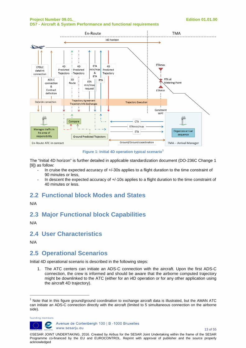
Here-below is a typical Initial 4D scenario which presents how ATC and flight crew interact during Initial 4D operations:
Project Number 09.01._ Edition 01.01.00 D57 - Aircraft & System Performance and functional requirements
13 of 55 ©SESAR JOINT UNDERTAKING, 2016. Created by Airbus for the SESAR Joint Undertaking within the frame of the SESAR Programme co-financed by the EU and EUROCONTROL. Reprint with approval of publisher and the source properly acknowledged
Figure 1: Initial 4D operation typical scenario1
The “Initial 4D horizon” is further detailed in applicable standardization document (DO-236C Change 1 [9]) as follow:
- In cruise the expected accuracy of +/-30s applies to a flight duration to the time constraint of 90 minutes or less,
- In descent the expected accuracy of +/-10s applies to a flight duration to the time constraint of 40 minutes or less.
2.2 Functional block Modes and States N/A
2.3 Major Functional block Capabilities N/A
2.4 User Characteristics N/A
2.5 Operational Scenarios Initial 4D operational scenario is described in the following steps:
1. The ATC centers can initiate an ADS-C connection with the aircraft. Upon the first ADS-C connection, the crew is informed and should be aware that the airborne computed trajectory might be downlinked to the ATC (either for an i4D operation or for any other application using the aircraft 4D trajectory).
1 Note that in this figure ground/ground coordination to exchange aircraft data is illustrated, but the AMAN ATC can initiate an ADS-C connection directly with the aircraft (limited to 5 simultaneous connection on the airborne side).
Project Number 09.01._ Edition 01.01.00 D57 - Aircraft & System Performance and functional requirements
14 of 55 ©SESAR JOINT UNDERTAKING, 2016. Created by Airbus for the SESAR Joint Undertaking within the frame of the SESAR Programme co-financed by the EU and EUROCONTROL. Reprint with approval of publisher and the source properly acknowledged
Wind and temperature data: weather forecast shall be inserted in the aircraft in order to ensure accuracy of RTA and 4D trajectory. If deemed necessary by the crew, the wind and temperature data can be updated through FOC or entered manually by the flight crew during the flight. Note: The FMS meteorological model has been enhanced to guarantee the time constraint reliability in the specified interval. Up to date wind and temperature data (10 levels of wind and temperature data along the descent) are necessary to perform an i4D operation with the required level of accuracy. It is crew responsibility to maintain wind and temperature FMS data up to date in order to provide ATC with reliable trajectory information.
2. Once a CPDLC datalink connection has been established between the aircraft and the ATC in
contact, the crew and the controller can communicate through CPDLC messages. Note: Unlike ADS-C contract, only one CPDLC connection is possible at a time between the aircraft and its ATC in contact.
3. ATC establishes an ADS-C contract with the aircraft and requests the downlink of an EPP
(Extended Projected Profile) report (demand, periodic or event) as defined in EUROCAE ED-228 [8] document. Notes: The ADS-C application is designed to provide automatic reports from an aircraft to an ATC ground system. The ATC specifies ADS-C contract type (on demand, periodic, or triggered by an event) he needs to establish with the aircraft. The Extended Projected Profile (EPP) provides to the ground the 4D trajectory (3D route + Estimated Time of Arrival for all the waypoints included in the EPP) and other information (flight modes, speed scheduled,...). The EPP report is based on the predictions computed by the FMS:
- It includes some general data not associated to waypoints - It includes a list of up to 128 points of significance for the construction of the
lateral and vertical trajectory. - The points are reported in the order the A/C will sequence them. - Only the points ahead of the A/C are reported - Waypoints are not only F-PLN waypoints, also other relevant points computed by
the FMS.
An EPP report may contain a maximum number of 128 waypoints.
4. If the current trajectory of the aircraft is not consistent with the trajectory expected by the ground or planned by the ground for it, ATC may elect to either accept the FMS trajectory or ATC may uplink a required route to the aircraft. The uplinked route may also contain speed/vertical elements.
5. Flight crew complies with the uplinked 3D route clearance and updates the ACTIVE flight plan
accordingly. The flight crew acknowledges the 3D route uplink message with a "WILCO" answer. An automatic downlink of 4D trajectory via ADS-C “EPP report” is triggered automatically after the flight plan update (on event ADS-C EPP report) or upon reception of an ATC request (on-demand ADS-C EPP report). Note: The flight crew may respond to the 3D clearance by “STANDBY” before sending “WILCO” in order to have more time to analyze the 3D route clearance.
Project Number 09.01._ Edition 01.01.00 D57 - Aircraft & System Performance and functional requirements
15 of 55 ©SESAR JOINT UNDERTAKING, 2016. Created by Airbus for the SESAR Joint Undertaking within the frame of the SESAR Programme co-financed by the EU and EUROCONTROL. Reprint with approval of publisher and the source properly acknowledged
6. If the arrival airport is equipped with an Arrival Manager using time constraints to tune and
organize the sequence of the arrival flights, a CTA (Controlled Time of Arrival) may be issued to the aircraft. To issue this CTA, in the case of Initial 4D aircraft, the Arrival Manager has at his disposal the following information on the waypoint of interest:
- The ETAmin/max interval, transmitted by the aircraft through an ADS-C on demand downlink “ETAmin/max report”,
- The ETA (Estimated Time of Arrival), transmitted by the aircraft through an ADS-C EPP report including the waypoint of interest, from the active flight plan.
Note: The "ETAmin/max interval" is displayed to the crew on the RTA page, associated to flight plan waypoints, and is considered as the "RTA reliable interval" and thus both wordings might be used in this document. The RTA interval reliability is guaranteed only within the limit of the Initial 4D horizon defined in the DO-236C Change 1 [9] and detailed in section 2.1.
7. ATC in contact uplinks to the aircraft the CTA constraint (with its associated required
accuracy) on waypoint of interest based on the AMAN (Arrival MANager) calculations.
8. After assessing the RTA feasibility, the flight crew acknowledges the CTA constraint uplink message with either a "WILCO" or “UNABLE” answer. If pilots accepted the CTA (i.e. send “WILCO” by datalink), they insert the RTA constraint and its required accuracy into the FMS. Otherwise, after being informed of the RTA rejection by the crew (i.e. “UNABLE” received by the controller in contact), the controller can either reinitiate the CTA negotiation process or cancel the operation and manage the aircraft with other tools (e.g. TTL/TTG). If the ATC has established the corresponding ADS-C contract “EPP Report” with the aircraft, the updated trajectory is downlinked to the ground.
9. The 4D trajectory is then flown in managed guidance mode (usually the aircraft is already in
managed guidance mode when the RTA is activated). ATC could evaluate conformance to the agreed 4D trajectory using ADS-C “EPP report”. Airborne systems provide an automatic time conformance monitoring function that informs the pilot through a cockpit message and the ground system through the downlink of an ADS-C EPP report including the RTA status (missed/made). When the pilot is aware of this non-conformance, he must warn the ATC by voice. Notes: Maintaining separation minima’s when flying the 4D trajectory is a responsibility of ATC and this task is not delegated to the aircraft. A conformance monitoring tool, based on ADS-C EPP reports processing could be available to the controller to detect any deviation from the agreed 4D trajectory.
When the time constrained waypoint is sequenced, Initial 4D operations are terminated.
2.6 Functional
2.6.1 Functional decomposition Initial 4D function is related to both navigation and communication enhancements allowing the aircraft to operate in future ATM 4D operations (in support of Initial 4D ATM operational concept - horizon 2018-2020).
From an operational point of view, the Initial 4D function supports the following:
- 3D route synchronization and time constraint (on a single waypoint at a time) agreement: Pilot/Controller agreement (via CPDLC) on the 4D trajectory to be flown (lateral route and any associated constraints (altitude/speed/time)).
Project Number 09.01._ Edition 01.01.00 D57 - Aircraft & System Performance and functional requirements
16 of 55 ©SESAR JOINT UNDERTAKING, 2016. Created by Airbus for the SESAR Joint Undertaking within the frame of the SESAR Programme co-financed by the EU and EUROCONTROL. Reprint with approval of publisher and the source properly acknowledged
- 4D trajectory execution: the on-board system is able to fly the negotiated 4D trajectory with sufficient accuracy (especially regarding RTA).
- 4D trajectory monitoring: crew has the capability to monitor the 4D trajectory including a time constraint.
- 4D trajectory downlink (via ADS-C): the on-board system is able to automatically send to the ground the 4D trajectory based on the contract established with the ATC center.
- Wind and temperature data: Datalink capability for updating wind and temperature data via FOC
From an A/C capabilities point of view, in addition to its basic 3D navigation capabilities, Initial 4D requires:
NAVIGATION:
- Time Prediction (flight planning: computation of accurate and reliable time estimates)
- Guidance
- Time Guidance Monitoring
- Reliable RTA interval computation
COMMUNICATION:
- Controller-Pilot Datalink Communication (CPDLC)
- Prediction Reporting (ADS-C)
- Datalink (FOC) capability to uplink wind and temperature data
HMI
2.6.2 Functional analysis This section describes briefly the functions performed by Initial 4D functions.
2.6.2.1 Time Prediction A basic RTA function is already available on some aircraft types.. However, the Initial 4D concept requires some improvements in the basic RTA function in order to ensure the required level of time reliability and accuracy, not available in current FMS standards:
- Introduction of an accuracy function which allows defining a required accuracy on an RTA in the flight plan, either before or after the RTA has been defined. Only two values can be chosen into the FMS, either manually or through the load functionality: +/-10s and +/-30s. A default value will be set automatically by the FMS to +/- 30s.
- Enhanced RTA algorithm, such that when inserted into the FMS within ETAmin/max interval, the RTA will be satisfied, considering its required accuracy in 95% of the cases. The FMS takes enough margins on predicted speed profile taking into account several sources of errors, the most relevant one being the wind/temperature error, based on an improved weather model which includes 10 levels of wind and temperature data. The FMS RTA algorithm will respect any altitude and speed restrictions for RTA speed computation. It also provides pilots with the possibility to modify the maximum allowable speed.
- RTA page HMI such as the Reliable RTA interval, RTA and ETA values are displayed on the RTA page. The FMS displays and allows to manually modify the “RTA Required Accuracy” parameter in the RTA page.
2.6.2.2 Guidance If the aircraft is in managed mode and an RTA is active, the Guidance Function consists, on top of basically guiding the aircraft along its 3D flight plan, in guiding the aircraft according to the predicted speed profile computed by the FMS to cross the specified waypoint at the specified time.
Project Number 09.01._ Edition 01.01.00 D57 - Aircraft & System Performance and functional requirements
17 of 55 ©SESAR JOINT UNDERTAKING, 2016. Created by Airbus for the SESAR Joint Undertaking within the frame of the SESAR Programme co-financed by the EU and EUROCONTROL. Reprint with approval of publisher and the source properly acknowledged
2.6.2.3 Time Guidance Monitoring During Initial 4D operations, the conformance to the 4D trajectory is monitored by the crew and possibly by ATC (through ADS-C report, if the ground is equipped with a conformance monitoring tool). According to the defined procedures, flight crew is requested to inform ATC by voice in case RTA becomes predicted unachievable. In order to allow the crew to monitor the aircraft conformance to the time constraint, several information and alert messages have been enhanced.
- RTA awareness While an aircraft is flying to an RTA, it adjusts its speed to cross the specified waypoint at the specified time. Once the RTA is inserted, feedback is required to ensure flight crew awareness of the aircraft specific speed management.
- RTA achievable/unachievable status
The FMS computes whether the RTA is predicted achievable in accordance with the required RTA accuracy. An RTA may be either “predicted achievable” or “predicted unachievable” before sequencing the RTA waypoint. As soon as the RTA becomes predicted unachievable, the crew is informed through specific alert message. If it has been specified in the ADS-C contract, a report can be automatically sent to the ATC with the RTA status.
2.6.2.4 Reliable RTA interval computation In order to support the time constraint agreement operation between flight crew and ATC, the FMS computes reliable minimum and maximum crossing time values (ETAmin/ETAmax) for any waypoint (on which a RTA can be defined), which are the reliable ETA assuming the aircraft flies respectively at its maximum/minimum allowed speed taking into account some margins.
The pilots will use the reliable RTA interval to assess whether or not the time constraint uplinked by the ATC is acceptable.
The FMS computes:
- The reliable ETAmin by using the maximum allowable RTA speed schedule
- The reliable ETAmax by using the minimum allowable RTA speed schedule
The FMS has to ensure that an RTA defined within reliable RTA interval will be met on a 95% probability basis. Thus it computes the RTA reliable interval taking into account wind and temperature uncertainties and any altitude and speed restrictions inserted in the flight plan. The RTA reliable interval displayed to the crew is thus taking into account some margins.
2.6.2.5 Controller-Pilot Datalink Communication (CPDLC) In the context of Initial 4D, the CPDLC application is used by the controller to send dedicated clearances.
A minimum set of uplink messages (UMs), selected from the complete list of messages implemented by the FANS function, has been defined in order to perform Initial 4D operations. These messages allow the ATC to uplink time, altitude and speed constraints as well as route clearance.
The crew will be able to answer the ATC instructions with downlink messages (DMs) through a dedicated interface: the DCDU (Datalink Control and Display Unit). The flight crew may select the appropriate answer on the DCDU and as soon as they confirm the choice by pressing the SEND key, the appropriate DM will be downlinked to the ATC as response to the previous uplink.
In order to facilitate the CPDLC management by the crew, a “LOAD” functionality from the ATSU to the relevant FMS page has been developed in the frame of the FANS function. Some of the Initial 4D uplink messages are loadable into the FMS’s flight plan. A dedicated key exists on the DCDU to inform the flight crew that the message is loadable and perform the corresponding action. This functionality aims to avoid the human errors which may arise if the crew had to manually insert the potentially complex instruction into the FMS. However, validating and activating the data loaded into the FMS remains the pilots’ responsibility after having performed the appropriate assessment.
Project Number 09.01._ Edition 01.01.00 D57 - Aircraft & System Performance and functional requirements
18 of 55 ©SESAR JOINT UNDERTAKING, 2016. Created by Airbus for the SESAR Joint Undertaking within the frame of the SESAR Programme co-financed by the EU and EUROCONTROL. Reprint with approval of publisher and the source properly acknowledged
2.6.2.6 Prediction Reporting (ADS-C) In the context of Initial 4D operation, the ADS-C application supports downlinking several reports to the ATC.
There are three types of ADS-C reports:
- On demand report: provide the capability for a ground system to request a single ADS-C report from an aircraft and to specify which information the system should include in the report (as defined in the corresponding standard (ref [8])).
- Periodic report: provide the capability for a ground system to request a periodic ADS-C report from an aircraft and specify which information the system should include in the report (as defined in the corresponding standard (ref [8])) and the rate at which the information is required.
- On event report: allow the ground system to request the avionics to send ADS-C reports when a specified event occurs. The ATC defines the type of events to be monitored.
Each ADS-C report is made of several groups of data, either mandatory or optional.
The initial 4D function supports the following groups:
- Basic group – mandatory
- EPP group – optional
- TOA Range group (ETAmin/max) – optional
- RTA Status group – optional
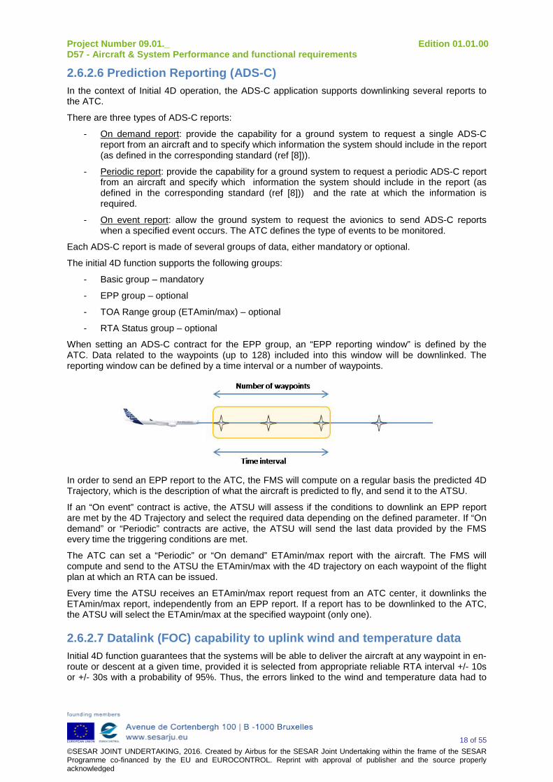
When setting an ADS-C contract for the EPP group, an “EPP reporting window” is defined by the ATC. Data related to the waypoints (up to 128) included into this window will be downlinked. The reporting window can be defined by a time interval or a number of waypoints.
In order to send an EPP report to the ATC, the FMS will compute on a regular basis the predicted 4D Trajectory, which is the description of what the aircraft is predicted to fly, and send it to the ATSU.
If an “On event” contract is active, the ATSU will assess if the conditions to downlink an EPP report are met by the 4D Trajectory and select the required data depending on the defined parameter. If “On demand” or “Periodic” contracts are active, the ATSU will send the last data provided by the FMS every time the triggering conditions are met.
The ATC can set a “Periodic” or “On demand” ETAmin/max report with the aircraft. The FMS will compute and send to the ATSU the ETAmin/max with the 4D trajectory on each waypoint of the flight plan at which an RTA can be issued.
Every time the ATSU receives an ETAmin/max report request from an ATC center, it downlinks the ETAmin/max report, independently from an EPP report. If a report has to be downlinked to the ATC, the ATSU will select the ETAmin/max at the specified waypoint (only one).
2.6.2.7 Datalink (FOC) capability to uplink wind and temperature data Initial 4D function guarantees that the systems will be able to deliver the aircraft at any waypoint in en-route or descent at a given time, provided it is selected from appropriate reliable RTA interval +/- 10s or +/- 30s with a probability of 95%. Thus, the errors linked to the wind and temperature data had to
Project Number 09.01._ Edition 01.01.00 D57 - Aircraft & System Performance and functional requirements
19 of 55 ©SESAR JOINT UNDERTAKING, 2016. Created by Airbus for the SESAR Joint Undertaking within the frame of the SESAR Programme co-financed by the EU and EUROCONTROL. Reprint with approval of publisher and the source properly acknowledged
be mitigated and an enhanced wind/temp model is used on board to handle the wind and temperature data:
The Initial 4D function minimizes the discrepancies between FMS-defined wind/temp profile (based on forecast wind and temperature data) and actual wind/temp profile by refining FMS descent wind and temperature modelling.
The FMS takes into account:
- Up to 10 forecast descent winds in active flight plan in order to compute the corresponding descent wind profile.
- Up to 10 forecast descent temperatures in active flight plan in order to compute the corresponding descent temperature profile.
Forecast wind and temperatures are entered using the FMS capability to request enhanced Wind/temp data through FOC.
It is the crew responsibility to ensure that the Wind/temp data used by the FMS to compute the predicted 4D trajectory are as up to date as possible, in order to ensure an accurate predicted 4D trajectory.
2.7 Service View N/A
Project Number 09.01._ Edition 01.01.00 D57 - Aircraft & System Performance and functional requirements
20 of 55 ©SESAR JOINT UNDERTAKING, 2016. Created by Airbus for the SESAR Joint Undertaking within the frame of the SESAR Programme co-financed by the EU and EUROCONTROL. Reprint with approval of publisher and the source properly acknowledged
3 Functional block Functional and non-Functional Requirements
3.1 Initial 4D Functional Requirements You will find here below the functional requirements linked to the Initial 4D function for civil aircraft (mainline and regional), military aircraft and rotorcraft. These requirements are lined to the 05.06.01 OSED and SPR document [13] and, in addition, an appendix A is dedicated to rotorcraft operational requirements not contained in any OSED or SPR documents and raised during P04.10 project activities.
The validation of the requirements (defined here below considered as “validated”) corresponds to the following Technology Readiness Levels (TRLs):
- TRL3 ‘Analytical and experimental critical function and/or characteristic proof of concept’ for requirements linked to 04.10 project.
- TRL4 ‘Component/subsystem validation in laboratory environment’ for requirements linked to 09.03 project.
- TRL6 ‘System/subsystem model or prototyping demonstration in a relevant end-to-end environment (ground or space)’ for requirements linked to 09.01 project.
Moreover, some requirements are considered as validated in the frame of 09.01, 09.03 and/or 04.10 projects; however, additional activities should be considered in order to validate the official release of datalink standardisation document [8].
3.1.1 Navigation Requirements
3.1.1.1 RTA function [REQ] Identifier REQ-09.01-TS-0.179 Requirement Initial 4D function shall provide the capability to define an RTA constraint on
any waypoint (except pseudo waypoint and FMS computed waypoint). Title RTA waypoint Status <Validated> Rationale RTA function is expected to provide operational benefit in all flight phase of a
flight. Initial 4D function does not support multi-RTA operations. RTA can be defined in FMS active, temporary (TMPY) and any secondary (SEC) flight plan (FMS offers capability to have 1 RTA defined in active flight plan and 1 RTA defined in each TMPY and SEC flight plan at the same time).
Category <Functional> Validation Method <Real Time Simulation> Verification Method <Review of Design> [REQ Trace] Relationship Linked Element Type Identifier Compliance <SATISFIES> <Enabler> A/C-11 <Full> <SATISFIES> <ATMS Requirement> REQ-05.06.01-Step 1SPR IT3-SAF1.0077 <Full> <SATISFIES> <ATMS Requirement> REQ-05.06.01-Step 1SPR IT3-SAF1.0072 <Partial> <ALLOCATED_TO> <Functional block> Navigation N/A <APPLIES_TO> <Operational Focus Area> OFA04.01.02 N/A <CHANGED_BECAUSE_OF> <Change Order> Previous Reference (D06): FRD-
INITIAL4D-179 N/A
<ALLOCATED_TO> <Project> P09.01 N/A <ALLOCATED_TO> <Project> P09.03 N/A <ALLOCATED_TO> <Project> P04.10 N/A [REQ]
Project Number 09.01._ Edition 01.01.00 D57 - Aircraft & System Performance and functional requirements
21 of 55 ©SESAR JOINT UNDERTAKING, 2016. Created by Airbus for the SESAR Joint Undertaking within the frame of the SESAR Programme co-financed by the EU and EUROCONTROL. Reprint with approval of publisher and the source properly acknowledged
Identifier REQ-09.01-TS-0.190 Requirement Initial 4D function shall provide the capability to define a required accuracy
related to the RTA value. Title RTA accuracy Status <DELETED> Rationale ATM requirements regarding RTA accuracy may be different within TMA or en-
route phase of flight. Since it is expected that flying high accuracy RTA will generate guidance order changes lead to fly less optimized and less comfortable trajectories (more margins to be taken into account in vertical profile computation etc.) with potential impact also on passenger comfort, engine wear etc. It is preferable to fly with high accuracy RTAs only when required.
Category <Functional> Validation Method N/A Verification Method N/A [REQ Trace] Relationship Linked Element Type Identifier Compliance <SATISFIES> <Enabler> N/A <Full> <SATISFIES> <ATMS Requirement> N/A <Full> <ALLOCATED_TO> <Functional block> N/A N/A <APPLIES_TO> <Operational Focus Area> N/A N/A <CHANGED_BECAUSE_OF> <Change Order> Previous Reference (D06): FRD-
INITIAL4D-190 DELETED Accuracy further defined in validation activities and detailed in REQ-09.01-TS-0.201
N/A
<ALLOCATED_TO> <Project> N/A N/A [REQ] Identifier REQ-09.01-TS-0.201 Requirement Initial 4D function shall allow to define the following required accuracy related
to the RTA value: +/-30s and +/-10s as defined in RTCA DO-236C Change 1 [9] / EUROCAE ED-75D [10].
Title RTA accuracy value Status <Validated> Rationale According to validation activities, +/-10s accuracy applies to TMA but +/-30s
could be enough in medium density, medium complexity TMA airspace, +/-30s applies to en-route. A default +/-30s accuracy value will be considered by the FMS in both en-route and TMA. These accuracy values are guaranteed only within the “Initial 4D horizon” as defined in DO-236C Change 1 [9] and detailed in section 2.1.
Category <Performance> Validation Method <Real Time Simulation> Verification Method <Review of Design> [REQ Trace] Relationship Linked Element Type Identifier Compliance <SATISFIES> <Enabler> A/C-11 <Full> <SATISFIES> <ATMS Requirement> REQ-05.06.01-OSED-SG07.0100 <Full> <SATISFIES> <ATMS Requirement> REQ-05.06.01-Step 1SPR IT3-SAF1.0098 <Full> <ALLOCATED_TO> <Functional block> Navigation N/A <APPLIES_TO> <Operational Focus Area> OFA04.01.02 N/A <CHANGED_BECAUSE_OF> <Change Order> Previous Reference (D06): FRD-
INITIAL4D-201 N/A
<ALLOCATED_TO> <Project> P09.01 N/A <ALLOCATED_TO> <Project> P09.03 N/A [REQ] Identifier REQ-09.01-TS-1.212
Project Number 09.01._ Edition 01.01.00 D57 - Aircraft & System Performance and functional requirements
22 of 55 ©SESAR JOINT UNDERTAKING, 2016. Created by Airbus for the SESAR Joint Undertaking within the frame of the SESAR Programme co-financed by the EU and EUROCONTROL. Reprint with approval of publisher and the source properly acknowledged
Requirement Initial 4D function shall compute an RTA “missed/made” status over the whole duration of an i4D operation.
- RTA status =”made” when the A/C is predicted to sequence the waypoint within the defined RTA accuracy tolerance.
- RTA status=”missed” when the aircraft is predicted to sequence the waypoint outside the defined RTA accuracy tolerance.
Title RTA status monitoring Status <Validated> Rationale When an RTA is being flown, flight crew shall have clear and unambiguous
feedback on A/C capacity to meet RTA. The RTA accuracy tolerance is a tolerance considered by the FMS on the RTA accuracy to avoid triggering an RTA missed as soon as the RTA accuracy is exceeded while the RTA is still predicted as achievable.
Category <Functional> Validation Method <Real Time Simulation> Verification Method <Review of Design> [REQ Trace] Relationship Linked Element Type Identifier Compliance <SATISFIES> <Enabler> A/C-11 <Full> <SATISFIES> <ATMS Requirement> REQ-05.06.01-OSED-SG07.0200 <Full> <SATISFIES> <ATMS Requirement> REQ-05.06.01-OSED-SG07.0300 <Full> <SATISFIES> <ATMS Requirement> REQ-05.06.01-Step 1SPR IT3-SAF1.0091 <Full> <SATISFIES> <ATMS Requirement> REQ-05.06.01-Step 1SPR IT3-SAF1.0095 <Full> <SATISFIES> <ATMS Requirement> REQ-05.06.01-Step 1SPR IT3-PRF1.0006 <Full> <ALLOCATED_TO> <Functional block> Alert N/A <APPLIES_TO> <Operational Focus Area> OFA04.01.02 N/A <CHANGED_BECAUSE_OF> <Change Order> Previous Reference (D06): FRD-
INITIAL4D-212 Requirement slightly reworded
N/A
<ALLOCATED_TO> <Project> P09.01 N/A <ALLOCATED_TO> <Project> P09.03 N/A <ALLOCATED_TO> <Project> P04.10 N/A [REQ] Identifier REQ-09.01-TS-1.225 Requirement Initial 4D function shall ensure that any RTA defined within associated reliable
RTA interval will be satisfied (considering its required accuracy) with reliability on a 95% probability basis. This shall include in particular robustness to wind and temperature errors as defined in RTCA DO-236C Change 1 [9] / EUROCAE ED-75D [10]
Title RTA reliability Status <Validated> Rationale 10s at 95 % in descent and 30s at 95% in en-route are the values defined in
RTCA DO-236C Change 1 [9] / EUROCAE ED-75D [10]. In order to ensure that any RTA defined within associated reliable RTA interval will be satisfied with reliability on a 95% probability basis (as defined in RTCA DO-236C Change 1 [9] / EUROCAE ED-75D [10]), the pilot has to fly the 4D trajectory in managed guidance mode. For Regional aircraft, reliable RTA interval shall take into account corresponding margin due to A/C performance model accuracy and due to the fact that managed guidance mode is not always available.
Category <Performance> Validation Method <Analytical Modelling> Verification Method <Analysis> [REQ Trace] Relationship Linked Element Type Identifier Compliance <SATISFIES> <Enabler> A/C-11 <Full> <SATISFIES> <ATMS Requirement> REQ-05.06.01-OSED-SG07.0100 <Full> <SATISFIES> <ATMS Requirement> REQ-05.06.01-Step 1SPR IT3-SAF1.0098 <Full>
Project Number 09.01._ Edition 01.01.00 D57 - Aircraft & System Performance and functional requirements
23 of 55 ©SESAR JOINT UNDERTAKING, 2016. Created by Airbus for the SESAR Joint Undertaking within the frame of the SESAR Programme co-financed by the EU and EUROCONTROL. Reprint with approval of publisher and the source properly acknowledged
<ALLOCATED_TO> <Functional block> Navigation N/A <APPLIES_TO> <Operational Focus Area> OFA04.01.02 N/A <CHANGED_BECAUSE_OF> <Change Order> Previous Reference (D06): FRD-
INITIAL4D-225 Standardisation document reference updated
N/A
<ALLOCATED_TO> <Project> P09.01 N/A <ALLOCATED_TO> <Project> P09.03 N/A [REQ] Identifier REQ-09.01-TS-1.236 Requirement The RTA speed target used for guidance shall be upper limited by “maximum
allowable RTA speed schedule” defined by the flight crew. This shall have no impact on RTA resulting performance (accuracy/reliability).
Title RTA maximum speed Status <Validated> Rationale This is to cope with cases where flight crew does not want to operate the A/C
at high speed (temporary A/C limitation, airline policy etc.). Consistency with corresponding reliable RTA interval has to be ensured. If Vmax is modified after RTA insertion, the RTA performance might be impacted. Vmax value entered by the flight crew is rejected by the system if Vmax is superior to the maximum VMO-DELTA/MMO-DELTA value considering all flight phases. If Vmax is accepted by the system, Min(Vmax; VMO-DELTA/MMO-DELTA of the current flight phase) is used for guidance; in conformance with REQ-09.01-TS-1.304.
Category <Functional> Validation Method <Real Time Simulation> Verification Method <Review of Design> [REQ Trace] Relationship Linked Element Type Identifier Compliance <SATISFIES> <Enabler> A/C-11 <Full> <SATISFIES> <ATMS Requirement> REQ-05.06.01-OSED-SG07.0100 <Full> <SATISFIES> <ATMS Requirement> REQ-05.06.01-Step 1SPR IT3-SAF1.0098 <Full> <ALLOCATED_TO> <Functional block> Navigation N/A <APPLIES_TO> <Operational Focus Area> OFA04.01.02 N/A <CHANGED_BECAUSE_OF> <Change Order> Previous Reference (D06):
FRD-INITIAL4D-236 N/A
<ALLOCATED_TO> <Project> P09.01 N/A <ALLOCATED_TO> <Project> P09.03 N/A <ALLOCATED_TO> <Project> P04.10 N/A [REQ] Identifier REQ-09.01-TS-0.933 Requirement The RTA speed target used for guidance shall be lower limited by the
“minimum allowable RTA speed schedule” defined by the FMS. This shall have no impact on RTA resulting performance (accuracy/reliability).
Title RTA minimum speed Status <DELETED> Rationale This is to allow the flight crew to comply with potential airline-specific
requirements and policy. ATC may also need to limit the minimum speed for operational reasons. Consistency with corresponding reliable RTA interval values needs to be insured. The minimum allowable RTA speed schedule has to be within the aircraft speed envelope and in conformance with any potential ATC-related constraints as required by REQ-09.01-TS-0.304. Note the technical feasibility and operational needs and benefits need to be analysed deeper.
Category <Functional> Validation Method N/A Verification Method N/A
Project Number 09.01._ Edition 01.01.00 D57 - Aircraft & System Performance and functional requirements
24 of 55 ©SESAR JOINT UNDERTAKING, 2016. Created by Airbus for the SESAR Joint Undertaking within the frame of the SESAR Programme co-financed by the EU and EUROCONTROL. Reprint with approval of publisher and the source properly acknowledged
[REQ Trace] Relationship Linked Element Type Identifier Compliance <SATISFIES> <Enabler> N/A <Full> <SATISFIES> <ATMS Requirement> N/A <Full> <ALLOCATED_TO> <Functional block> N/A N/A <APPLIES_TO> <Operational Focus Area> N/A N/A <CHANGED_BECAUSE_OF> <Change Order> Previous Reference (D06): FRD-
INITIAL4D-933 DELETED After validation activities, there is no need for the pilot to change the minimum allowable RTA speed schedule.
N/A
<ALLOCATED_TO> <Project> N/A N/A [REQ] Identifier REQ-09.01-TS-1.271 Requirement Initial 4D function design should maximize aircraft reliable RTA interval
considering Maximum and Minimum allowable RTA speed schedule. Title RTA reliable interval Status <Validated> Rationale In future ATM concepts, RTA will be used to sequence inbound aircraft at a
particular point. If the reliable RTA interval is too small, the ATC controller will not have enough flexibility to optimize air traffic flow. Maximizing reliable RTA interval is an operational need from the controller, however at the end of validation activities, no minimum window size value has been defined and this requirement exists as an operational objective to answer this need. This requirement is a design objective and can be implemented independently from the other requirements.
Category <Functional> Validation Method <Real Time Simulation> Verification Method <Review of Design> [REQ Trace] Relationship Linked Element Type Identifier Compliance <SATISFIES> <Enabler> A/C-11 <Full> <SATISFIES> <ATMS Requirement> REQ-05.06.01-OSED-SG07.0100 <Full> <SATISFIES> <ATMS Requirement> REQ-05.06.01-Step 1SPR IT3-SAF1.0098 <Full> <ALLOCATED_TO> <Functional block> Navigation N/A <APPLIES_TO> <Operational Focus Area> OFA04.01.02 N/A <CHANGED_BECAUSE_OF> <Change Order> Previous Reference (D06):
FRD-INITIAL4D-271 Requirement slightly reworded.
N/A
<ALLOCATED_TO> <Project> P09.01 N/A <ALLOCATED_TO> <Project> P09.03 N/A <ALLOCATED_TO> <Project> P04.10 N/A [REQ] Identifier REQ-09.01-TS-1.282 Requirement When RTA is active and A/C is in managed guidance mode, RTA function
induced speed increments should be minimized (in terms of amplitude) to an operationally acceptable level.
Title RTA speed increments Status <Validated> Rationale According to ATC feedback, an RTA design with a series of small speed
increment/decrement and frequent speed updates as soon as these required adjustments are known/identified by the FMS is preferred to an RTA design with a limited number of speed updates occurrence and infrequent (i.e. waiting for bigger steps before being activated by the FMS), large high speed increments/decrements. Operationally acceptable, according to current operations, means that A/C speed variations of less than 5% from the flight plan speed are not subjected to
Project Number 09.01._ Edition 01.01.00 D57 - Aircraft & System Performance and functional requirements
25 of 55 ©SESAR JOINT UNDERTAKING, 2016. Created by Airbus for the SESAR Joint Undertaking within the frame of the SESAR Programme co-financed by the EU and EUROCONTROL. Reprint with approval of publisher and the source properly acknowledged
ATC notification. This requirement is a design objective and can be implemented independently from the other requirements.
Category <Performance> Validation Method <Flight Trial> Verification Method <Review of Design> [REQ Trace] Relationship Linked Element Type Identifier Compliance <SATISFIES> <Enabler> A/C-11 <Full> <SATISFIES> <ATMS Requirement> REQ-05.06.01-Step 1SPR IT3-SAF1.0109 <Full> <ALLOCATED_TO> <Functional block> Navigation N/A <APPLIES_TO> <Operational Focus Area> OFA04.01.02 N/A <CHANGED_BECAUSE_OF> <Change Order> Previous Reference (D06):
FRD-INITIAL4D-282 Requirement slightly reworded and clarified.
N/A
<ALLOCATED_TO> <Project> P09.01 N/A <ALLOCATED_TO> <Project> P09.03 N/A [REQ] Identifier REQ-09.01-TS-1.304 Requirement RTA speed target used for guidance shall take into account flight plan
constraints in managed guidance mode. Title Flight Plan constraints Status <Validated> Rationale RTA computation needs to take into account other constraints.
RTA design will have to account for reduced reliable RTA interval in speed restricted segment within the Initial 4D horizon as defined in section 2.1 (below speed limit altitude for example). Navigation (lateral/vertical) requirements from RTCA DO-236C Change 1 [9] / EUROCAE ED-75D [10] are applicable to RTA flight. In case of incompatibility between RTA and any other constraint, the non-conformance is solved through pilot/controller communication.
Category <Functional> Validation Method <Real Time Simulation> Verification Method <Review of Design> [REQ Trace] Relationship Linked Element Type Identifier Compliance <SATISFIES> <Enabler> A/C-11 <Full> <SATISFIES> <ATMS Requirement> REQ-05.06.01-Step 1SPR IT3-SAF1.0099 <Full> <ALLOCATED_TO> <Functional block> Navigation N/A <APPLIES_TO> <Operational Focus Area> OFA04.01.02 N/A <CHANGED_BECAUSE_OF> <Change Order> Previous Reference (D06): FRD-
INITIAL4D-304 Requirement slightly reworded Standardisation document reference updated
N/A
<ALLOCATED_TO> <Project> P09.01 N/A <ALLOCATED_TO> <Project> P09.03 N/A <ALLOCATED_TO> <Project> P04.10 N/A [REQ] Identifier REQ-09.01-TS-1.934 Requirement RTA defined into the system shall not be deleted by the system if a selected
mode is engaged. Upon reversion to managed guidance mode, Initial 4D function shall resume speed guidance according to the defined RTA.
Title Selected mode with active RTA Status <Validated> Rationale This is to facilitate potential ATC conflict resolution efforts.
In case of ATC intervention, flight crew will potentially use selected mode. Once the ATC intervention is complete, the function needs to be able to
Project Number 09.01._ Edition 01.01.00 D57 - Aircraft & System Performance and functional requirements
26 of 55 ©SESAR JOINT UNDERTAKING, 2016. Created by Airbus for the SESAR Joint Undertaking within the frame of the SESAR Programme co-financed by the EU and EUROCONTROL. Reprint with approval of publisher and the source properly acknowledged
resume the i4D operation in order to comply with the RTA previously instructed. During the intervention, speed might be frozen by the system or the flight crew. Note that in this case, RTA reliability may not be guaranteed. Not applicable to Military A/C: Avionics modifications would be required.
Category <Functional> Validation Method <Real Time Simulation> Verification Method <Review of Design> [REQ Trace] Relationship Linked Element Type Identifier Compliance <SATISFIES> <Enabler> A/C-11 <Full> <SATISFIES> <ATMS Requirement> REQ-05.06.01-Step 1SPR IT3-SAF1.0099 <Full> <ALLOCATED_TO> <Functional block> Navigation N/A <APPLIES_TO> <Operational Focus Area> OFA04.01.02 N/A <CHANGED_BECAUSE_OF> <Change Order> Previous Reference (D06): FRD-
INITIAL4D-934-4 Rationale for no military applicability added
N/A
<ALLOCATED_TO> <Project> P09.01 N/A <ALLOCATED_TO> <Project> P04.10 N/A [REQ] Identifier REQ-09.01-TS-0.941-4 Requirement Any running ASPA S&M manoeuvre shall be automatically stopped if a time
constraint is entered in the active F-PLN. Title ASPA S&M and i4D exclusivity Status <DELETED> Rationale The i4D function and ASPA S&M application are considered as exclusive: it is
not possible to keep a given spacing and insure that a time constraint will be made on a waypoint at the same time. Regional A/C will not be able to perform ASPA S&M operations in short/mid-term.
Category <Operational> Validation Method N/A Verification Method N/A [REQ Trace] Relationship Linked Element Type Identifier Compliance <SATISFIES> <Enabler> A/C-11 <Full> <SATISFIES> <Enabler> A/C-15 <Full> <SATISFIES> <ATMS Requirement> N/A N/A <ALLOCATED_TO> <Functional block> Navigation N/A <APPLIES_TO> <Operational Focus Area> OFA04.01.02 N/A <APPLIES_TO> <Operational Focus Area> OFA03.02.01 N/A <CHANGED_BECAUSE_OF> <Change Order> Previous Reference (D06): FRD-
INITIAL4D-941-4 DELETED ASPA operations outside of P09.01 scope.
N/A
<ALLOCATED_TO> <Project> N/A N/A [REQ] Identifier REQ-09.01-TS-2.003 Requirement When sequencing the RTA waypoint, or upon the cancellation of the RTA when
the aircraft is already in descent, the aircraft shall maintain the last speed required to meet the RTA, unless otherwise instructed by ATC.
Title I4D stopped Status <Validated> Rationale This is to avoid important speed variations while in TMA, as also identified in
REQ-09.01-TS-1.282. When the RTA is cancelled while in cruise, the aircraft will resume its optimal speed except if a new RTA is inserted in the FMS.
Category <Functional> Validation Method <Real Time Simulation>
Project Number 09.01._ Edition 01.01.00 D57 - Aircraft & System Performance and functional requirements
27 of 55 ©SESAR JOINT UNDERTAKING, 2016. Created by Airbus for the SESAR Joint Undertaking within the frame of the SESAR Programme co-financed by the EU and EUROCONTROL. Reprint with approval of publisher and the source properly acknowledged
Verification Method <Review of Design> [REQ Trace] Relationship Linked Element Type Identifier Compliance <SATISFIES> <Enabler> A/C-11 <Full> <SATISFIES> <ATMS Requirement> REQ-05.06.01-OSED-SG08.0100 <Full> <SATISFIES> <ATMS Requirement> REQ-05.06.01-Step 1SPR IT3-SAF1.0113 <Full> <SATISFIES> <ATMS Requirement> REQ-05.06.01-Step 1SPR IT3-SAF1.0115 <Full> <ALLOCATED_TO> <Functional block> Navigation N/A <APPLIES_TO> <Operational Focus Area> OFA04.01.02 N/A <CHANGED_BECAUSE_OF> <Change Order> New requirement N/A <ALLOCATED_TO> <Project> P09.01 N/A <ALLOCATED_TO> <Project> P04.10 N/A [REQ] Identifier REQ-09.01-TS-0.942 Requirement Any running i4D function shall be automatically stopped if ASPA S&M
application is activated. Title I4D and ASPA S&M exclusivity Status <Validated> Rationale The i4D function and ASPA S&M application are considered as exclusive: it is
not possible to keep a time constraint and ensure a given spacing will be maintained at the same time. Regional A/C will not be able to perform ASPA S&M operations in short/mid-term.
Category <Functional> Validation Method <Real Time Simulation> Verification Method <Review of Design> [REQ Trace] Relationship Linked Element Type Identifier Compliance <SATISFIES> <Enabler> A/C-11 <Full> <SATISFIES> <Enabler> A/C-15 <Full> <ALLOCATED_TO> <Functional block> Navigation N/A <APPLIES_TO> <Operational Focus Area> OFA04.01.02 N/A <APPLIES_TO> <Operational Focus Area> OFA03.02.01 N/A <CHANGED_BECAUSE_OF> <Change Order> Previous Reference (D06): FRD-
INITIAL4D-942-4 N/A
<ALLOCATED_TO> <Project> P09.01 N/A <ALLOCATED_TO> <Project> P09.03 N/A <ALLOCATED_TO> <Project> P04.10 N/A
3.1.1.2 Computation of Reliable ETAmin and Reliable ETAmax [REQ] Identifier REQ-09.01-TS-1.338 Requirement Initial 4D function shall include the capability to compute reliable ETAmin and
ETAmax values for any flight plan waypoint eligible for an RTA. Title Reliable ETAmin/max interval on waypoint Status <Validated> Rationale Reliable ETAmin and reliable ETAmax values represent the lower and the
upper bound of the reliable RTA interval respectively and will be used in support of RTA negotiation with ATC controller. Reliable RTA interval is computed for all flight plan waypoints where an RTA can be defined. Only one reliable RTA interval is displayed on-board the aircraft and downlinked to the ground at a time.
Category <Functional> Validation Method <Real Time Simulation> Verification Method <Review of Design> [REQ Trace]
Project Number 09.01._ Edition 01.01.00 D57 - Aircraft & System Performance and functional requirements
28 of 55 ©SESAR JOINT UNDERTAKING, 2016. Created by Airbus for the SESAR Joint Undertaking within the frame of the SESAR Programme co-financed by the EU and EUROCONTROL. Reprint with approval of publisher and the source properly acknowledged
Relationship Linked Element Type Identifier Compliance <SATISFIES> <Enabler> A/C-11 <Full> <SATISFIES> <ATMS Requirement> REQ-05.06.01-Step 1SPR IT3-SAF1.0071 <Full> <ALLOCATED_TO> <Functional block> Navigation N/A <APPLIES_TO> <Operational Focus Area> OFA04.01.02 N/A <CHANGED_BECAUSE_OF> <Change Order> Previous Reference (D06): FRD-
INITIAL4D-338 N/A
<ALLOCATED_TO> <Project> P09.01 N/A <ALLOCATED_TO> <Project> P09.03 N/A <ALLOCATED_TO> <Project> P04.10 N/A [REQ] Identifier REQ-09.01-TS-1.349 Requirement Reliable ETAmin shall be computed by using the aircraft speed envelope
upper restricted by the “maximum allowable RTA speed schedule” taking into account wind/temp margins.
Title Reliable ETAmin computation Status <Validated> Rationale Wind error margins shall be added to ensure that any RTA set within reliable
RTA interval will be sequenced within required accuracy tolerance with 95% probability. This maximum allowable RTA speed profile will be alterable by the crew and will be used for both reliable ETAmin computation and as a maximum allowable speed for speed guidance while in RTA operation.
Category <Functional> Validation Method <Analytical Modelling> Verification Method <Review of Design> [REQ Trace] Relationship Linked Element Type Identifier Compliance <SATISFIES> <Enabler> A/C-11 <Full> <SATISFIES> <ATMS Requirement> REQ-05.06.01-Step 1SPR IT3-SAF1.0071 <Full> <ALLOCATED_TO> <Functional block> Navigation N/A <APPLIES_TO> <Operational Focus Area> OFA04.01.02 N/A <CHANGED_BECAUSE_OF> <Change Order> Previous Reference (D06): FRD-
INITIAL4D-349 Rationale updated
N/A
<ALLOCATED_TO> <Project> P09.01 N/A <ALLOCATED_TO> <Project> P09.03 N/A <ALLOCATED_TO> <Project> P04.10 N/A [REQ] Identifier REQ-09.01-TS-1.937 Requirement Reliable ETAmax shall be computed by using the aircraft speed envelope
taking into account wind/temp margins. Title Reliable ETAmax computation Status <Validated> Rationale Minimum allowable speed schedule is not alterable by flight crew. Category <Functional> Validation Method <Analytical Modelling> Verification Method <Review of Design> [REQ Trace] Relationship Linked Element Type Identifier Compliance <SATISFIES> <Enabler> A/C-11 <Full> <SATISFIES> <ATMS Requirement> REQ-05.06.01-Step 1SPR IT3-SAF1.0071 <Full> <ALLOCATED_TO> <Functional block> Navigation N/A <APPLIES_TO> <Operational Focus Area> OFA04.01.02 N/A <CHANGED_BECAUSE_OF> <Change Order> Previous Reference (D06): FRD-
INITIAL4D-937 Requirement and rationale updated to align the content on last validation results.
N/A
<ALLOCATED_TO> <Project> P09.01 N/A
Project Number 09.01._ Edition 01.01.00 D57 - Aircraft & System Performance and functional requirements
29 of 55 ©SESAR JOINT UNDERTAKING, 2016. Created by Airbus for the SESAR Joint Undertaking within the frame of the SESAR Programme co-financed by the EU and EUROCONTROL. Reprint with approval of publisher and the source properly acknowledged
<ALLOCATED_TO> <Project> P09.03 N/A <ALLOCATED_TO> <Project> P04.10 N/A [REQ] Identifier REQ-09.01-TS-0.360 Requirement Both reliable ETAmin and ETAmax values shall be computed with a resolution
of one second. Title ETAmin and ETAmax resolution Status <Validated> Rationale This is to ensure consistency with RTA required accuracy (which can be as low
as +/-10s). Category <Functional> Validation Method <Real Time Simulation> Verification Method <Review of Design> [REQ Trace] Relationship Linked Element Type Identifier Compliance <SATISFIES> <Enabler> A/C-11 <Full> <SATISFIES> <ATMS Requirement> REQ-05.06.01-OSED-SG07.0100 <Full> <SATISFIES> <ATMS Requirement> REQ-05.06.01-Step 1SPR IT3-SAF1.0098 <Full> <ALLOCATED_TO> <Functional block> Navigation N/A <APPLIES_TO> <Operational Focus Area> OFA04.01.02 N/A <CHANGED_BECAUSE_OF> <Change Order> Previous Reference (D06): FRD-
INITIAL4D-360 N/A
<ALLOCATED_TO> <Project> P09.01 N/A <ALLOCATED_TO> <Project> P09.03 N/A <ALLOCATED_TO> <Project> P04.10 N/A
3.1.1.3 Time estimates accuracy [REQ] Identifier REQ-09.01-TS-1.372 Requirement Initial 4D function shall provide the capability to compute time estimates for
any flight plan waypoint eligible for RTA with a resolution of one second. Title ETA resolution Status <Validated> Rationale The predicted 4D trajectory downlinked to ATC will include ETA for all flight
plan waypoint with a resolution of 1s. According to current navigation system design, ETA for RTA constrained waypoint is already computed and displayed on RTA page with a resolution of 1s.
Category <Functional> Validation Method <Real Time Simulation> Verification Method <Review of Design> [REQ Trace] Relationship Linked Element Type Identifier Compliance <SATISFIES> <Enabler> A/C-11 <Full> <SATISFIES> <ATMS Requirement> REQ-05.06.01-Step 1SPR IT3-SAF1.0071 <Full> <ALLOCATED_TO> <Functional block> Navigation N/A <APPLIES_TO> <Operational Focus Area> OFA04.01.02 N/A <CHANGED_BECAUSE_OF> <Change Order> Previous Reference (D06): FRD-
INITIAL4D-372 N/A
<ALLOCATED_TO> <Project> P09.01 N/A <ALLOCATED_TO> <Project> P09.03 N/A <ALLOCATED_TO> <Project> P04.10 N/A [REQ] Identifier REQ-09.01-TS-1.383 Requirement Initial 4D function shall have the capability to compute ETA such that the
maximum ETA error is less than 1% of the flight time remaining to the fix the ETA is calculated for or 10seconds, whichever is greater, for the entered
Project Number 09.01._ Edition 01.01.00 D57 - Aircraft & System Performance and functional requirements
30 of 55 ©SESAR JOINT UNDERTAKING, 2016. Created by Airbus for the SESAR Joint Undertaking within the frame of the SESAR Programme co-financed by the EU and EUROCONTROL. Reprint with approval of publisher and the source properly acknowledged
conditions and flight plan. Title ETA accuracy Status <Validated> Rationale New ATM concepts focus on A/C improved predictability. Having accurate ETA
will improve accuracy of 4D trajectory computed by navigation systems and downlinked to ATC. The objective is to provide predictions accurate enough to allow ATC to build and maintain a sequence of A/C based on transmitted data. Having more accurate time estimates will also have beneficial impact on i4D function (need for reduced ETA error compensation via speed adjustments). This performance requirement on ETA reliability is based on DO236C Change 1 [9] and EUROCAE ED-75D [10]. An aircraft already compliant with DO236 is compliant with this requirement.
Category <Performance> Validation Method <Analytical Modelling> Verification Method <Review of Design> [REQ Trace] Relationship Linked Element Type Identifier Compliance <SATISFIES> <Enabler> A/C-11 <Full> <SATISFIES> <ATMS Requirement> N/A N/A <ALLOCATED_TO> <Functional block> Navigation N/A <APPLIES_TO> <Operational Focus Area> OFA04.01.02 N/A <CHANGED_BECAUSE_OF> <Change Order> Previous Reference (D06): FRD-
INITIAL4D-383 Requirement wording aligned on ED-75D [10] formulation.
N/A
<ALLOCATED_TO> <Project> P09.01 N/A <ALLOCATED_TO> <Project> P09.03 N/A
3.1.2 Communication Requirements Typical Data Link System architecture for regional aircraft is different from datalink structure for mainline aircraft (i.e. different exchanges with FMS, limited CPDLC, ADS-C and FOC functionalities). CPDLC and ADS-C requirements are based on WG78/SC214 SPR ver. H [7].Communication requirements are analysed in further detail in P09.01 D58 “Interface requirements between the aircraft and the ATC systems” [11].
3.1.2.1 General [REQ] Identifier REQ-09.01-TS-0.407 Requirement ADS-C and CPDLC datalink applications shall be installed and active on board
the A/C. Title Datalink capability availability Status <Validated> Rationale Initial 4D function features communication exchanges with ATC via CPDLC
and downlink of both 4D trajectory and reliable ETAmin/ETAmax values via ADS-C. This requirement is considered as validated in the frame of 09.01 and 09.03 projects; however, additional activities should be considered in order to validate the official release of datalink standardisation document [8].
Category <Functional> Validation Method <Real Time Simulation> Verification Method <Test> [REQ Trace] Relationship Linked Element Type Identifier Compliance <SATISFIES> <Enabler> A/C-31a <Full> <SATISFIES> <Enabler> A/C-37a <Full> <SATISFIES> <ATMS Requirement> REQ-05.06.01-OSED-SG01.0100 <Full> <SATISFIES> <ATMS Requirement> REQ-05.06.01-OSED-SG01.0110 <Full>
Project Number 09.01._ Edition 01.01.00 D57 - Aircraft & System Performance and functional requirements
31 of 55 ©SESAR JOINT UNDERTAKING, 2016. Created by Airbus for the SESAR Joint Undertaking within the frame of the SESAR Programme co-financed by the EU and EUROCONTROL. Reprint with approval of publisher and the source properly acknowledged
<SATISFIES> <ATMS Requirement> REQ-05.06.01-OSED-SG01.0200 <Full> <SATISFIES> <ATMS Requirement> REQ-05.06.01-OSED-SG01.0210 <Full> <SATISFIES> <ATMS Requirement> REQ-05.06.01-Step 1SPR IT3-SAF1.0008 <Full> <SATISFIES> <ATMS Requirement> REQ-05.06.01-Step 1SPR IT3-SAF1.0009 <Full> <ALLOCATED_TO> <Functional block> Communication N/A <APPLIES_TO> <Operational Focus Area> OFA04.01.02 N/A <CHANGED_BECAUSE_OF> <Change Order> Previous Reference (D06): FRD-
INITIAL4D-407 N/A
<ALLOCATED_TO> <Project> P09.01 N/A <ALLOCATED_TO> <Project> P09.03 N/A [REQ] Identifier REQ-09.01-TS-0.429 Requirement All ETA, reliable ETAmin/max, RTA value to be exchanged between A/C and
ATC via CPDLC or ADS-C shall have a resolution of 1sec. Title Datalink time information resolution Status <Validated> Rationale This is due to 1s ETA resolution required by DO-236C Change 1.
This requirement is considered as validated in the frame of 09.01 and 09.03 projects; however, additional activities should be considered in order to validate the official release of datalink standardisation document [8].
Category <Functional> Validation Method <Real Time Simulation> Verification Method <Review of Design> [REQ Trace] Relationship Linked Element Type Identifier Compliance <SATISFIES> <Enabler> A/C-31a <Full> <SATISFIES> <Enabler> A/C-37a <Full> <SATISFIES> <ATMS Requirement> REQ-05.06.01-Step 1SPR IT3-SAF1.0012 <Partial> <ALLOCATED_TO> <Functional block> Communication N/A <APPLIES_TO> <Operational Focus Area> OFA04.01.02 N/A <CHANGED_BECAUSE_OF> <Change Order> Previous Reference (D06): FRD-
INITIAL4D-429 RTCA and EUROCAE applicable document updated
N/A
<ALLOCATED_TO> <Project> P09.01 N/A <ALLOCATED_TO> <Project> P09.03 N/A
3.1.2.2 CPDLC [REQ] Identifier REQ-09.01-TS-1.418 Requirement As a general requirement, the management of all Initial 4D CPDLC messages
shall comply with general requirements related to FANS C function. Title I4D CPDLC message compatibility with FANS C Status <Validated> Rationale This is to ensure compatibility between different Airbus functions.
Applicable to Airbus aircraft only. FANS C: Airbus function which manages datalink communication in European continental airspace. This requirement is considered as validated in the frame of 09.01 project; however, additional activities should be considered in order to validate the official release of datalink standardisation document [8].
Category <Functional> Validation Method <Real Time Simulation> Verification Method <Review of Design> [REQ Trace] Relationship Linked Element Type Identifier Compliance <SATISFIES> <Enabler> A/C-31a <Full> <SATISFIES> <ATMS Requirement> REQ-05.06.01-Step 1SPR IT3-SAF1.0008 <Full> <SATISFIES> <ATMS Requirement> REQ-05.06.01-Step 1SPR IT3-SAF1.0009 <Full>
Project Number 09.01._ Edition 01.01.00 D57 - Aircraft & System Performance and functional requirements
32 of 55 ©SESAR JOINT UNDERTAKING, 2016. Created by Airbus for the SESAR Joint Undertaking within the frame of the SESAR Programme co-financed by the EU and EUROCONTROL. Reprint with approval of publisher and the source properly acknowledged
<ALLOCATED_TO> <Functional block> Communication N/A <APPLIES_TO> <Operational Focus Area> OFA04.01.02 N/A <CHANGED_BECAUSE_OF> <Change Order> Previous Reference (D06): FRD-
INITIAL4D-418 Document reference updated Rationale updated
N/A
<ALLOCATED_TO> <Project> P09.01 N/A [REQ] Identifier REQ-09.01-TS-1.935 Requirement As a general requirement, the loading of all Initial 4D CPDLC messages shall
comply with requirements related to FANS C function. Title I4D CPDLC message compatibility with FANS C Status <Validated> Rationale This is to ensure compatibility between different Airbus functions.
Applicable to Airbus aircraft only. FANS C: Airbus function which manages datalink communication in European continental airspace. This requirement is considered as validated in the frame of 09.01 project; however, additional activities should be considered in order to validate the official release of datalink standardisation document [8].
Category <Functional> Validation Method <Real Time Simulation> Verification Method <Review of Design> [REQ Trace] Relationship Linked Element Type Identifier Compliance <SATISFIES> <Enabler> A/C-31a <Full> <SATISFIES> <ATMS Requirement> REQ-05.06.01-Step 1SPR IT3-SAF1.0008 <Full> <SATISFIES> <ATMS Requirement> REQ-05.06.01-Step 1SPR IT3-SAF1.0009 <Full> <ALLOCATED_TO> <Functional block> Communication N/A <APPLIES_TO> <Operational Focus Area> OFA04.01.02 N/A <CHANGED_BECAUSE_OF> <Change Order> Previous Reference (D06): FRD-
INITIAL4D-935-4 Document reference updated Rationale updated
N/A
<ALLOCATED_TO> <Project> P09.01 N/A
[REQ] Identifier REQ-09.01-TS-1.001 Requirement As a general requirement, the management of Initial 4D CPDLC shall comply
with messages as defined in P09.01 SESAR document D58 [11], based on draft versions of EUROCAE ED-228A [8].
Title CPDLC message definition Status <Validated> Rationale This corresponds to the set of messages required to operate Initial 4D function.
The supported set of messages in the quoted standard is presented in interoperability P09.01 SESAR document D58 [11].The entire set of message might not be supported due to technical limitations or low operational interest. This requirement is considered as validated in the frame of 09.01 and 09.03 projects; however, additional activities should be considered in order to validate the official release of datalink standardisation document [8].
Category <Functional> Validation Method <Real Time Simulation> Verification Method <Review of Design> [REQ Trace] Relationship Linked Element Type Identifier Compliance <SATISFIES> <Enabler> A/C-31a <Full> <SATISFIES> <ATMS Requirement> REQ-05.06.01-OSED-SG01.0120 <Full> <SATISFIES> <ATMS Requirement> REQ-05.06.01-Step 1SPR IT3-SAF1.0009 <Full>
Project Number 09.01._ Edition 01.01.00 D57 - Aircraft & System Performance and functional requirements
33 of 55 ©SESAR JOINT UNDERTAKING, 2016. Created by Airbus for the SESAR Joint Undertaking within the frame of the SESAR Programme co-financed by the EU and EUROCONTROL. Reprint with approval of publisher and the source properly acknowledged
<ALLOCATED_TO> <Functional block> Communication N/A <APPLIES_TO> <Operational Focus Area> OFA04.01.02 N/A <CHANGED_BECAUSE_OF> <Change Order> Previous Reference (D06): NEW-
INITIAL4D-001 Requirement updated with reference to applicable EUROCAE datalink standard and SESAR Interoperability document.
N/A
<ALLOCATED_TO> <Project> P09.01 N/A <ALLOCATED_TO> <Project> P09.03 N/A [REQ] Identifier REQ-09.01-TS-1.002 Requirement The Initial 4D function shall support the automatic upload of 3D route
clearances with time, altitude or speed constraints as required P09.01 SESAR document D58 [11], based on draft versions of EUROCAE ED-228A [8].
Title CPDLC 3D route clearance upload Status <Validated> Rationale As required in EUROCAE ED-228A [8].
This corresponds to CPDLC “load” selection on DCDU/mailbox. This requirement is considered as validated in the frame of 09.01 and 09.03 projects; however, additional activities should be considered in order to validate the official release of datalink standardisation document [8].
Category <Functional> Validation Method <Real Time Simulation> Verification Method <Review of Design> [REQ Trace] Relationship Linked Element Type Identifier Compliance <SATISFIES> <Enabler> A/C-31a <Full> <SATISFIES> <ATMS Requirement> REQ-05.06.01-Step 1SPR IT3-SAF1.0038 <Full> <ALLOCATED_TO> <Functional block> Communication N/A <APPLIES_TO> <Operational Focus Area> OFA04.01.02 N/A <CHANGED_BECAUSE_OF> <Change Order> Previous Reference (D06): NEW-
INITIAL4D-002 Requirement and rationale updated with reference to applicable EUROCAE datalink standard and SESAR Interoperability document.
N/A
<ALLOCATED_TO> <Project> P09.01 N/A <ALLOCATED_TO> <Project> P09.03 N/A
3.1.2.3 Airborne Dependent Surveillance – Contract (ADS-C) [REQ] Identifier REQ-09.01-TS-1.590 Requirement Initial 4D function shall provide the capability to process and manage ADS-C
“EPP request and report contract” as defined in P09.01 SESAR document D58 [11], based on draft versions of EUROCAE ED-228A [8].
Title EPP contract Status <Validated> Rationale ADS-C is used to downlink aircraft predicted 4D trajectory to support (among
others) 3D route synchronisation, 4D trajectory monitoring and use by ATC which are one of key enablers for Initial 4D concept. The ADS-C EPP report will include 4D trajectory. The usage of this report may be based on “On Event”, “Periodic” or “On Demand” contract. This requirement is considered as validated in the frame of 09.01 and 09.03 projects; however, additional activities should be considered in order to validate the official release of datalink standardisation document [8].
Category <Functional> Validation Method <Real Time Simulation> Verification Method <Review of Design>
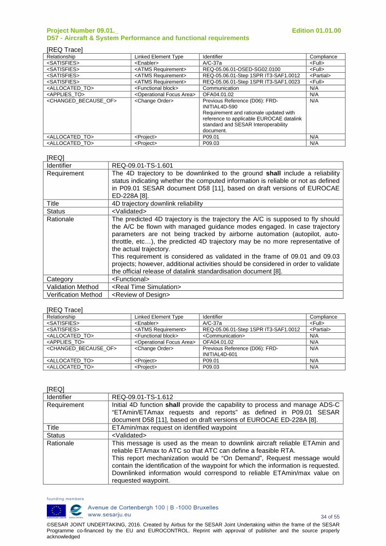
Project Number 09.01._ Edition 01.01.00 D57 - Aircraft & System Performance and functional requirements
34 of 55 ©SESAR JOINT UNDERTAKING, 2016. Created by Airbus for the SESAR Joint Undertaking within the frame of the SESAR Programme co-financed by the EU and EUROCONTROL. Reprint with approval of publisher and the source properly acknowledged
[REQ Trace] Relationship Linked Element Type Identifier Compliance <SATISFIES> <Enabler> A/C-37a <Full> <SATISFIES> <ATMS Requirement> REQ-05.06.01-OSED-SG02.0100 <Full> <SATISFIES> <ATMS Requirement> REQ-05.06.01-Step 1SPR IT3-SAF1.0012 <Partial> <SATISFIES> <ATMS Requirement> REQ-05.06.01-Step 1SPR IT3-SAF1.0023 <Full> <ALLOCATED_TO> <Functional block> Communication N/A <APPLIES_TO> <Operational Focus Area> OFA04.01.02 N/A <CHANGED_BECAUSE_OF> <Change Order> Previous Reference (D06): FRD-
INITIAL4D-590 Requirement and rationale updated with reference to applicable EUROCAE datalink standard and SESAR Interoperability document.
N/A
<ALLOCATED_TO> <Project> P09.01 N/A <ALLOCATED_TO> <Project> P09.03 N/A [REQ] Identifier REQ-09.01-TS-1.601 Requirement The 4D trajectory to be downlinked to the ground shall include a reliability
status indicating whether the computed information is reliable or not as defined in P09.01 SESAR document D58 [11], based on draft versions of EUROCAE ED-228A [8].
Title 4D trajectory downlink reliability Status <Validated> Rationale The predicted 4D trajectory is the trajectory the A/C is supposed to fly should
the A/C be flown with managed guidance modes engaged. In case trajectory parameters are not being tracked by airborne automation (autopilot, auto-throttle, etc…), the predicted 4D trajectory may be no more representative of the actual trajectory. This requirement is considered as validated in the frame of 09.01 and 09.03 projects; however, additional activities should be considered in order to validate the official release of datalink standardisation document [8].
Category <Functional> Validation Method <Real Time Simulation> Verification Method <Review of Design> [REQ Trace] Relationship Linked Element Type Identifier Compliance <SATISFIES> <Enabler> A/C-37a <Full> <SATISFIES> <ATMS Requirement> REQ-05.06.01-Step 1SPR IT3-SAF1.0012 <Partial> <ALLOCATED_TO> <Functional block> <Communication> N/A <APPLIES_TO> <Operational Focus Area> OFA04.01.02 N/A <CHANGED_BECAUSE_OF> <Change Order> Previous Reference (D06): FRD-
INITIAL4D-601 N/A
<ALLOCATED_TO> <Project> P09.01 N/A <ALLOCATED_TO> <Project> P09.03 N/A
[REQ] Identifier REQ-09.01-TS-1.612 Requirement Initial 4D function shall provide the capability to process and manage ADS-C
“ETAmin/ETAmax requests and reports” as defined in P09.01 SESAR document D58 [11], based on draft versions of EUROCAE ED-228A [8].
Title ETAmin/max request on identified waypoint Status <Validated> Rationale This message is used as the mean to downlink aircraft reliable ETAmin and
reliable ETAmax to ATC so that ATC can define a feasible RTA. This report mechanization would be “On Demand”, Request message would contain the identification of the waypoint for which the information is requested. Downlinked information would correspond to reliable ETAmin/max value on requested waypoint.
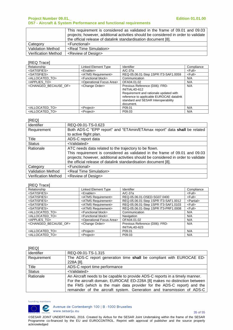
Project Number 09.01._ Edition 01.01.00 D57 - Aircraft & System Performance and functional requirements
35 of 55 ©SESAR JOINT UNDERTAKING, 2016. Created by Airbus for the SESAR Joint Undertaking within the frame of the SESAR Programme co-financed by the EU and EUROCONTROL. Reprint with approval of publisher and the source properly acknowledged
This requirement is considered as validated in the frame of 09.01 and 09.03 projects; however, additional activities should be considered in order to validate the official release of datalink standardisation document [8].
Category <Functional> Validation Method <Real Time Simulation> Verification Method <Review of Design> [REQ Trace] Relationship Linked Element Type Identifier Compliance <SATISFIES> <Enabler> A/C-37a <Full> <SATISFIES> <ATMS Requirement> REQ-05.06.01-Step 1SPR IT3-SAF1.0059 <Full> <ALLOCATED_TO> <Functional block> Communication N/A <APPLIES_TO> <Operational Focus Area> OFA04.01.02 N/A <CHANGED_BECAUSE_OF> <Change Order> Previous Reference (D06): FRD-
INITIAL4D-612 Requirement and rationale updated with reference to applicable EUROCAE datalink standard and SESAR Interoperability document.
N/A
<ALLOCATED_TO> <Project> P09.01 N/A <ALLOCATED_TO> <Project> P09.03 N/A [REQ] Identifier REQ-09.01-TS-0.623 Requirement Both ADS-C “EPP report” and “ETAmin/ETAmax report” data shall be related
to active flight plan. Title ADS-C report data Status <Validated> Rationale ATC needs data related to the trajectory to be flown.
This requirement is considered as validated in the frame of 09.01 and 09.03 projects; however, additional activities should be considered in order to validate the official release of datalink standardisation document [8].
Category <Functional> Validation Method <Real Time Simulation> Verification Method <Review of Design> [REQ Trace] Relationship Linked Element Type Identifier Compliance <SATISFIES> <Enabler> A/C-37a <Full> <SATISFIES> <ATMS Requirement> REQ-05.06.01-OSED-SG07.0400 <Full> <SATISFIES> <ATMS Requirement> REQ-05.06.01-Step 1SPR IT3-SAF1.0012 <Partial> <SATISFIES> <ATMS Requirement> REQ-05.06.01-Step 1SPR IT3-SAF1.0103 <Full> <SATISFIES> <ATMS Requirement> REQ-05.06.01-Step 1SPR IT3-PRF1.0008 <Full> <ALLOCATED_TO> <Functional block> Communication N/A <ALLOCATED_TO> <Functional block> Navigation N/A <APPLIES_TO> <Operational Focus Area> OFA04.01.02 N/A <CHANGED_BECAUSE_OF> <Change Order> Previous Reference (D06): FRD-
INITIAL4D-623 N/A
<ALLOCATED_TO> <Project> P09.01 N/A <ALLOCATED_TO> <Project> P09.03 N/A [REQ] Identifier REQ-09.01-TS-1.315 Requirement The ADS-C report generation time shall be compliant with EUROCAE ED-
228A [8]. Title ADS-C report time performance Status <Validated> Rationale An Aircraft needs to be capable to provide ADS-C reports in a timely manner.
For the aircraft domain, EUROCAE ED-228A [8] makes no distinction between the FMS (which is the main data provider for the ADS-C report) and the remainder of the aircraft system. Generation and transmission of ADS-C
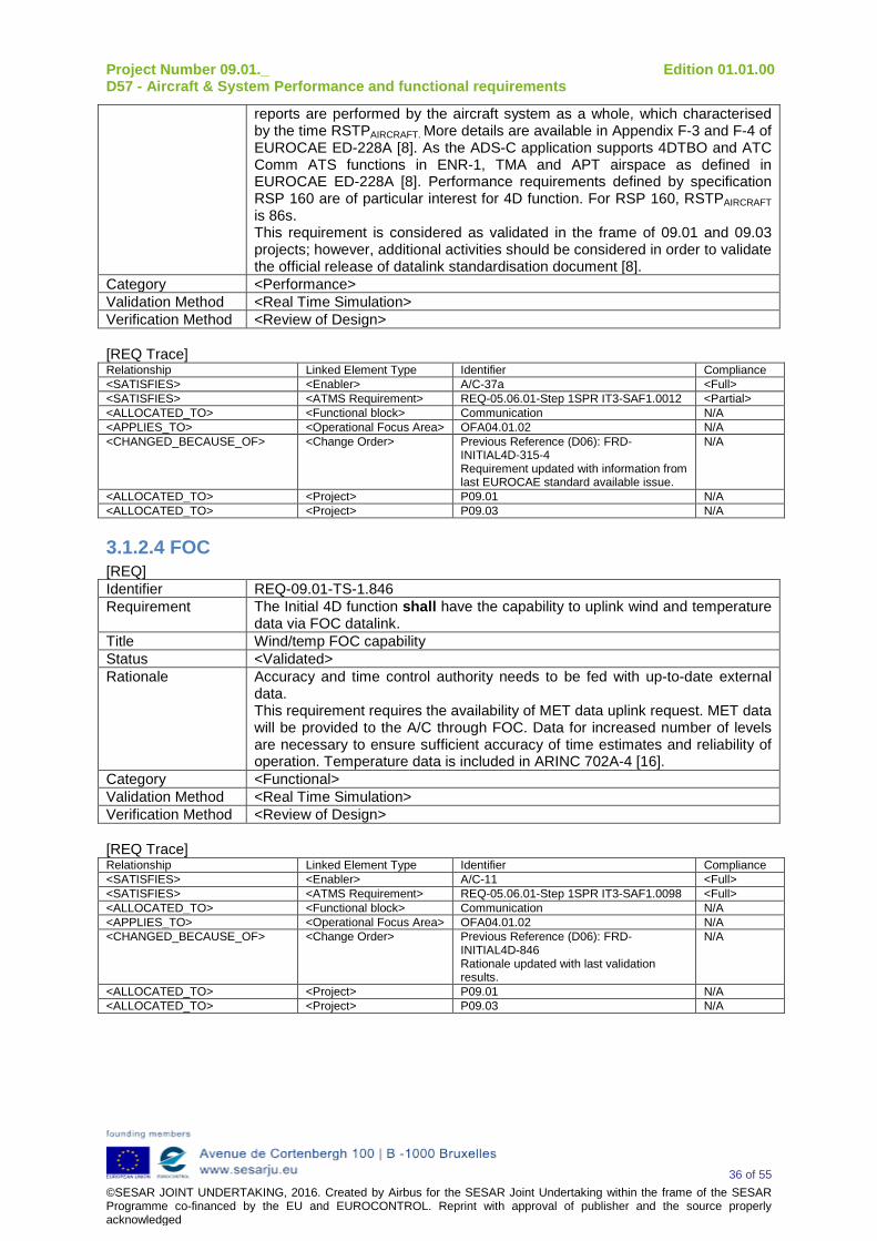
Project Number 09.01._ Edition 01.01.00 D57 - Aircraft & System Performance and functional requirements
36 of 55 ©SESAR JOINT UNDERTAKING, 2016. Created by Airbus for the SESAR Joint Undertaking within the frame of the SESAR Programme co-financed by the EU and EUROCONTROL. Reprint with approval of publisher and the source properly acknowledged
reports are performed by the aircraft system as a whole, which characterised by the time RSTPAIRCRAFT. More details are available in Appendix F-3 and F-4 of EUROCAE ED-228A [8]. As the ADS-C application supports 4DTBO and ATC Comm ATS functions in ENR-1, TMA and APT airspace as defined in EUROCAE ED-228A [8]. Performance requirements defined by specification RSP 160 are of particular interest for 4D function. For RSP 160, RSTPAIRCRAFT is 86s. This requirement is considered as validated in the frame of 09.01 and 09.03 projects; however, additional activities should be considered in order to validate the official release of datalink standardisation document [8].
Category <Performance> Validation Method <Real Time Simulation> Verification Method <Review of Design> [REQ Trace] Relationship Linked Element Type Identifier Compliance <SATISFIES> <Enabler> A/C-37a <Full> <SATISFIES> <ATMS Requirement> REQ-05.06.01-Step 1SPR IT3-SAF1.0012 <Partial> <ALLOCATED_TO> <Functional block> Communication N/A <APPLIES_TO> <Operational Focus Area> OFA04.01.02 N/A <CHANGED_BECAUSE_OF> <Change Order> Previous Reference (D06): FRD-
INITIAL4D-315-4 Requirement updated with information from last EUROCAE standard available issue.
N/A
<ALLOCATED_TO> <Project> P09.01 N/A <ALLOCATED_TO> <Project> P09.03 N/A
3.1.2.4 FOC [REQ] Identifier REQ-09.01-TS-1.846 Requirement The Initial 4D function shall have the capability to uplink wind and temperature
data via FOC datalink. Title Wind/temp FOC capability Status <Validated> Rationale Accuracy and time control authority needs to be fed with up-to-date external
data. This requirement requires the availability of MET data uplink request. MET data will be provided to the A/C through FOC. Data for increased number of levels are necessary to ensure sufficient accuracy of time estimates and reliability of operation. Temperature data is included in ARINC 702A-4 [16].
Category <Functional> Validation Method <Real Time Simulation> Verification Method <Review of Design> [REQ Trace] Relationship Linked Element Type Identifier Compliance <SATISFIES> <Enabler> A/C-11 <Full> <SATISFIES> <ATMS Requirement> REQ-05.06.01-Step 1SPR IT3-SAF1.0098 <Full> <ALLOCATED_TO> <Functional block> Communication N/A <APPLIES_TO> <Operational Focus Area> OFA04.01.02 N/A <CHANGED_BECAUSE_OF> <Change Order> Previous Reference (D06): FRD-
INITIAL4D-846 Rationale updated with last validation results.
N/A
<ALLOCATED_TO> <Project> P09.01 N/A <ALLOCATED_TO> <Project> P09.03 N/A
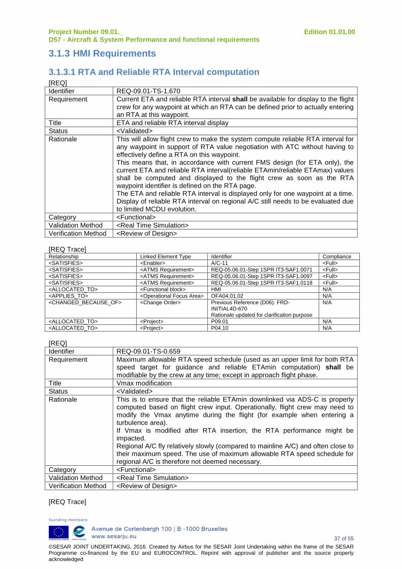
Project Number 09.01._ Edition 01.01.00 D57 - Aircraft & System Performance and functional requirements
37 of 55 ©SESAR JOINT UNDERTAKING, 2016. Created by Airbus for the SESAR Joint Undertaking within the frame of the SESAR Programme co-financed by the EU and EUROCONTROL. Reprint with approval of publisher and the source properly acknowledged
3.1.3 HMI Requirements
3.1.3.1 RTA and Reliable RTA Interval computation [REQ] Identifier REQ-09.01-TS-1.670 Requirement Current ETA and reliable RTA interval shall be available for display to the flight
crew for any waypoint at which an RTA can be defined prior to actually entering an RTA at this waypoint.
Title ETA and reliable RTA interval display Status <Validated> Rationale This will allow flight crew to make the system compute reliable RTA interval for
any waypoint in support of RTA value negotiation with ATC without having to effectively define a RTA on this waypoint. This means that, in accordance with current FMS design (for ETA only), the current ETA and reliable RTA interval(reliable ETAmin/reliable ETAmax) values shall be computed and displayed to the flight crew as soon as the RTA waypoint identifier is defined on the RTA page. The ETA and reliable RTA interval is displayed only for one waypoint at a time. Display of reliable RTA interval on regional A/C still needs to be evaluated due to limited MCDU evolution.
Category <Functional> Validation Method <Real Time Simulation> Verification Method <Review of Design> [REQ Trace] Relationship Linked Element Type Identifier Compliance <SATISFIES> <Enabler> A/C-11 <Full> <SATISFIES> <ATMS Requirement> REQ-05.06.01-Step 1SPR IT3-SAF1.0071 <Full> <SATISFIES> <ATMS Requirement> REQ-05.06.01-Step 1SPR IT3-SAF1.0097 <Full> <SATISFIES> <ATMS Requirement> REQ-05.06.01-Step 1SPR IT3-SAF1.0118 <Full> <ALLOCATED_TO> <Functional block> HMI N/A <APPLIES_TO> <Operational Focus Area> OFA04.01.02 N/A <CHANGED_BECAUSE_OF> <Change Order> Previous Reference (D06): FRD-
INITIAL4D-670 Rationale updated for clarification purpose
N/A
<ALLOCATED_TO> <Project> P09.01 N/A <ALLOCATED_TO> <Project> P04.10 N/A [REQ] Identifier REQ-09.01-TS-0.659 Requirement Maximum allowable RTA speed schedule (used as an upper limit for both RTA
speed target for guidance and reliable ETAmin computation) shall be modifiable by the crew at any time; except in approach flight phase.
Title Vmax modification Status <Validated> Rationale This is to ensure that the reliable ETAmin downlinked via ADS-C is properly
computed based on flight crew input. Operationally, flight crew may need to modify the Vmax anytime during the flight (for example when entering a turbulence area). If Vmax is modified after RTA insertion, the RTA performance might be impacted. Regional A/C fly relatively slowly (compared to mainline A/C) and often close to their maximum speed. The use of maximum allowable RTA speed schedule for regional A/C is therefore not deemed necessary.
Category <Functional> Validation Method <Real Time Simulation> Verification Method <Review of Design> [REQ Trace]
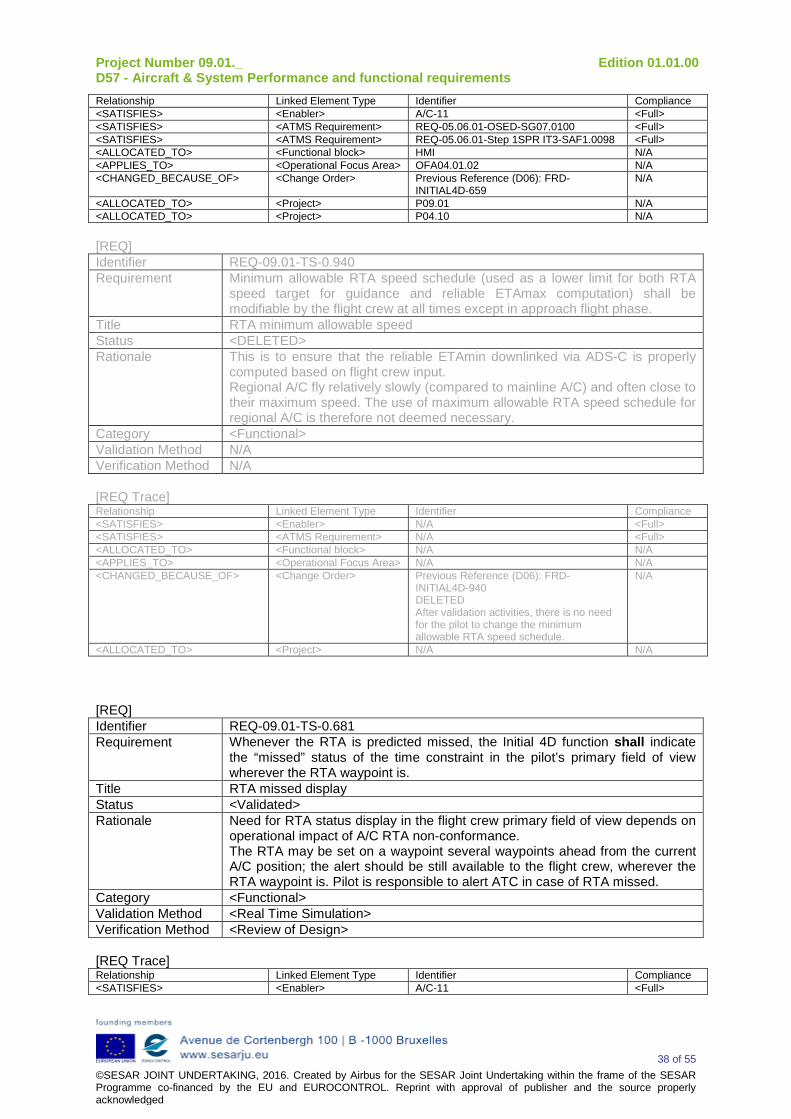
Project Number 09.01._ Edition 01.01.00 D57 - Aircraft & System Performance and functional requirements
38 of 55 ©SESAR JOINT UNDERTAKING, 2016. Created by Airbus for the SESAR Joint Undertaking within the frame of the SESAR Programme co-financed by the EU and EUROCONTROL. Reprint with approval of publisher and the source properly acknowledged
Relationship Linked Element Type Identifier Compliance <SATISFIES> <Enabler> A/C-11 <Full> <SATISFIES> <ATMS Requirement> REQ-05.06.01-OSED-SG07.0100 <Full> <SATISFIES> <ATMS Requirement> REQ-05.06.01-Step 1SPR IT3-SAF1.0098 <Full> <ALLOCATED_TO> <Functional block> HMI N/A <APPLIES_TO> <Operational Focus Area> OFA04.01.02 N/A <CHANGED_BECAUSE_OF> <Change Order> Previous Reference (D06): FRD-
INITIAL4D-659 N/A
<ALLOCATED_TO> <Project> P09.01 N/A <ALLOCATED_TO> <Project> P04.10 N/A [REQ] Identifier REQ-09.01-TS-0.940 Requirement Minimum allowable RTA speed schedule (used as a lower limit for both RTA
speed target for guidance and reliable ETAmax computation) shall be modifiable by the flight crew at all times except in approach flight phase.
Title RTA minimum allowable speed Status <DELETED> Rationale This is to ensure that the reliable ETAmin downlinked via ADS-C is properly
computed based on flight crew input. Regional A/C fly relatively slowly (compared to mainline A/C) and often close to their maximum speed. The use of maximum allowable RTA speed schedule for regional A/C is therefore not deemed necessary.
Category <Functional> Validation Method N/A Verification Method N/A [REQ Trace] Relationship Linked Element Type Identifier Compliance <SATISFIES> <Enabler> N/A <Full> <SATISFIES> <ATMS Requirement> N/A <Full> <ALLOCATED_TO> <Functional block> N/A N/A <APPLIES_TO> <Operational Focus Area> N/A N/A <CHANGED_BECAUSE_OF> <Change Order> Previous Reference (D06): FRD-
INITIAL4D-940 DELETED After validation activities, there is no need for the pilot to change the minimum allowable RTA speed schedule.
N/A
<ALLOCATED_TO> <Project> N/A N/A [REQ] Identifier REQ-09.01-TS-0.681 Requirement Whenever the RTA is predicted missed, the Initial 4D function shall indicate
the “missed” status of the time constraint in the pilot’s primary field of view wherever the RTA waypoint is.
Title RTA missed display Status <Validated> Rationale Need for RTA status display in the flight crew primary field of view depends on
operational impact of A/C RTA non-conformance. The RTA may be set on a waypoint several waypoints ahead from the current A/C position; the alert should be still available to the flight crew, wherever the RTA waypoint is. Pilot is responsible to alert ATC in case of RTA missed.
Category <Functional> Validation Method <Real Time Simulation> Verification Method <Review of Design> [REQ Trace] Relationship Linked Element Type Identifier Compliance <SATISFIES> <Enabler> A/C-11 <Full>
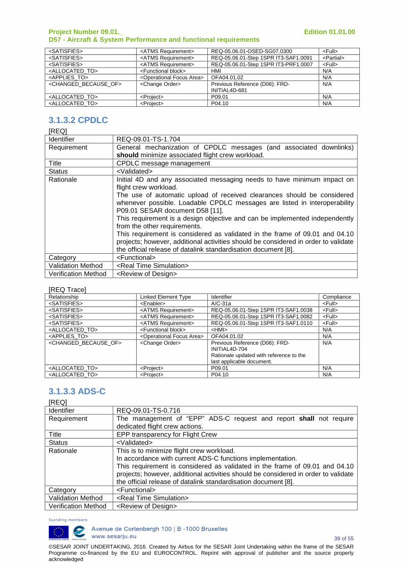
Project Number 09.01._ Edition 01.01.00 D57 - Aircraft & System Performance and functional requirements
39 of 55 ©SESAR JOINT UNDERTAKING, 2016. Created by Airbus for the SESAR Joint Undertaking within the frame of the SESAR Programme co-financed by the EU and EUROCONTROL. Reprint with approval of publisher and the source properly acknowledged
<SATISFIES> <ATMS Requirement> REQ-05.06.01-OSED-SG07.0300 <Full> <SATISFIES> <ATMS Requirement> REQ-05.06.01-Step 1SPR IT3-SAF1.0091 <Partial> <SATISFIES> <ATMS Requirement> REQ-05.06.01-Step 1SPR IT3-PRF1.0007 <Full> <ALLOCATED_TO> <Functional block> HMI N/A <APPLIES_TO> <Operational Focus Area> OFA04.01.02 N/A <CHANGED_BECAUSE_OF> <Change Order> Previous Reference (D06): FRD-
INITIAL4D-681 N/A
<ALLOCATED_TO> <Project> P09.01 N/A <ALLOCATED_TO> <Project> P04.10 N/A
3.1.3.2 CPDLC [REQ] Identifier REQ-09.01-TS-1.704 Requirement General mechanization of CPDLC messages (and associated downlinks)
should minimize associated flight crew workload. Title CPDLC message management Status <Validated> Rationale Initial 4D and any associated messaging needs to have minimum impact on
flight crew workload. The use of automatic upload of received clearances should be considered whenever possible. Loadable CPDLC messages are listed in interoperability P09.01 SESAR document D58 [11]. This requirement is a design objective and can be implemented independently from the other requirements. This requirement is considered as validated in the frame of 09.01 and 04.10 projects; however, additional activities should be considered in order to validate the official release of datalink standardisation document [8].
Category <Functional> Validation Method <Real Time Simulation> Verification Method <Review of Design> [REQ Trace] Relationship Linked Element Type Identifier Compliance <SATISFIES> <Enabler> A/C-31a <Full> <SATISFIES> <ATMS Requirement> REQ-05.06.01-Step 1SPR IT3-SAF1.0038 <Full> <SATISFIES> <ATMS Requirement> REQ-05.06.01-Step 1SPR IT3-SAF1.0082 <Full> <SATISFIES> <ATMS Requirement> REQ-05.06.01-Step 1SPR IT3-SAF1.0110 <Full> <ALLOCATED_TO> <Functional block> <HMI> N/A <APPLIES_TO> <Operational Focus Area> OFA04.01.02 N/A <CHANGED_BECAUSE_OF> <Change Order> Previous Reference (D06): FRD-
INITIAL4D-704 Rationale updated with reference to the last applicable document.
N/A
<ALLOCATED_TO> <Project> P09.01 N/A <ALLOCATED_TO> <Project> P04.10 N/A
3.1.3.3 ADS-C [REQ] Identifier REQ-09.01-TS-0.716 Requirement The management of “EPP” ADS-C request and report shall not require
dedicated flight crew actions. Title EPP transparency for Flight Crew Status <Validated> Rationale This is to minimize flight crew workload.
In accordance with current ADS-C functions implementation. This requirement is considered as validated in the frame of 09.01 and 04.10 projects; however, additional activities should be considered in order to validate the official release of datalink standardisation document [8].
Category <Functional> Validation Method <Real Time Simulation> Verification Method <Review of Design>
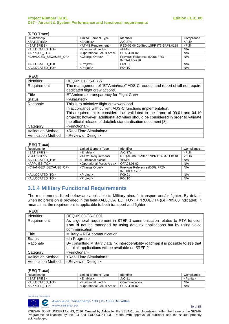
Project Number 09.01._ Edition 01.01.00 D57 - Aircraft & System Performance and functional requirements
40 of 55 ©SESAR JOINT UNDERTAKING, 2016. Created by Airbus for the SESAR Joint Undertaking within the frame of the SESAR Programme co-financed by the EU and EUROCONTROL. Reprint with approval of publisher and the source properly acknowledged
[REQ Trace] Relationship Linked Element Type Identifier Compliance <SATISFIES> <Enabler> A/C-37a <Full> <SATISFIES> <ATMS Requirement> REQ-05.06.01-Step 1SPR IT3-SAF1.0118 <Full> <ALLOCATED_TO> <Functional block> <HMI> N/A <APPLIES_TO> <Operational Focus Area> OFA04.01.02 N/A <CHANGED_BECAUSE_OF> <Change Order> Previous Reference (D06): FRD-
INITIAL4D-716 N/A
<ALLOCATED_TO> <Project> P09.01 N/A <ALLOCATED_TO> <Project> P04.10 N/A [REQ] Identifier REQ-09.01-TS-0.727 Requirement The management of “ETAmin/max” ADS-C request and report shall not require
dedicated flight crew actions. Title ETAmin/max transparency for Flight Crew Status <Validated> Rationale This is to minimize flight crew workload.
In accordance with current ADS-C functions implementation. This requirement is considered as validated in the frame of 09.01 and 04.10 projects; however, additional activities should be considered in order to validate the official release of datalink standardisation document [8].
Category <Functional> Validation Method <Real Time Simulation> Verification Method <Review of Design> [REQ Trace] Relationship Linked Element Type Identifier Compliance <SATISFIES> <Enabler> A/C-37a <Full> <SATISFIES> <ATMS Requirement> REQ-05.06.01-Step 1SPR IT3-SAF1.0118 <Full> <ALLOCATED_TO> <Functional block> <HMI> N/A <APPLIES_TO> <Operational Focus Area> OFA04.01.02 N/A <CHANGED_BECAUSE_OF> <Change Order> Previous Reference (D06): FRD-
INITIAL4D-727 N/A
<ALLOCATED_TO> <Project> P09.01 N/A <ALLOCATED_TO> <Project> P04.10 N/A
3.1.4 Military Functional Requirements The requirements listed below are applicable to Military aircraft, transport and/or fighter. By default when no precision is provided in the field <ALLOCATED_TO> | <PROJECT> (i.e. P09.03 indicated), it means that the requirement is applicable to both transport and fighter.
[REQ] Identifier REQ-09.03-TS-2.001 Requirement As a general requirement in STEP 1 communication related to RTA function
should not be managed by using datalink applications but by using voice communication.
Title Military – RTA communication Status <In Progress> Rationale By consulting Military Datalink Interoperability roadmap it is possible to see that
datalink applications will be available on STEP 2 Category <Functional> Validation Method <Real Time Simulation> Verification Method <Review of Design> [REQ Trace] Relationship Linked Element Type Identifier Compliance <SATISFIES> <Enabler> A/C-11 <Partial> <ALLOCATED_TO> <Functional block> Communication N/A <APPLIES_TO> <Operational Focus Area> OFA04.01.02 N/A
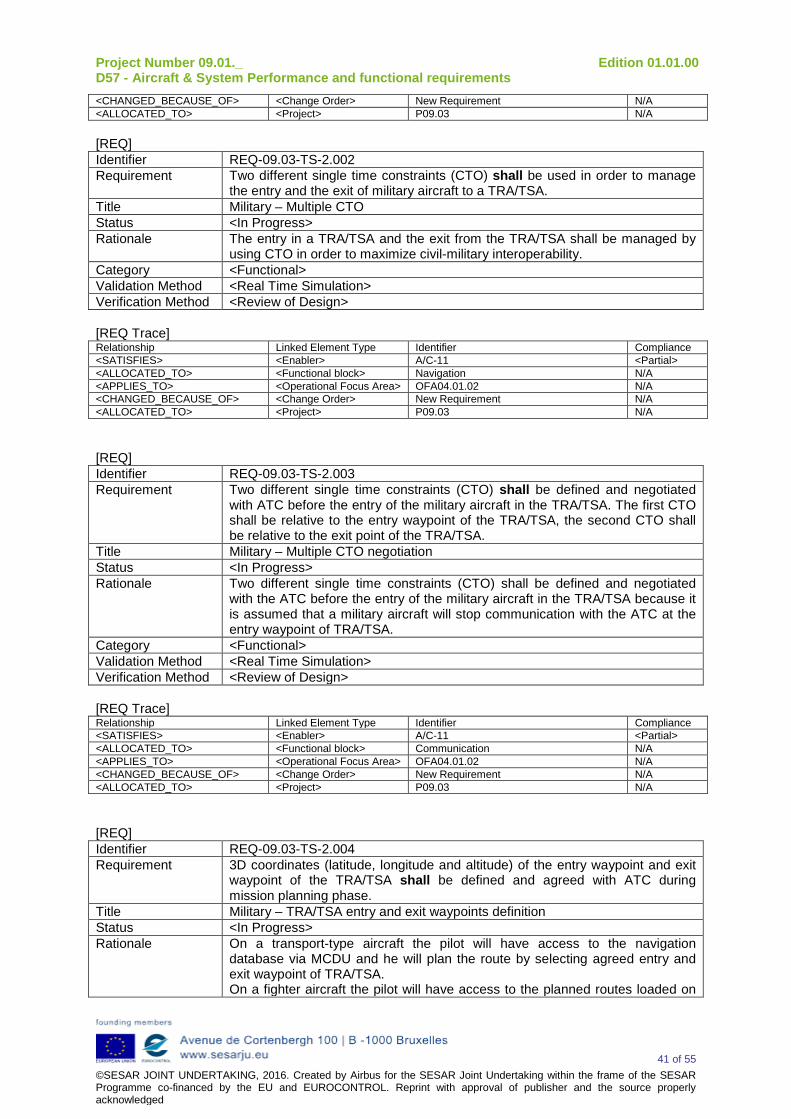
Project Number 09.01._ Edition 01.01.00 D57 - Aircraft & System Performance and functional requirements
41 of 55 ©SESAR JOINT UNDERTAKING, 2016. Created by Airbus for the SESAR Joint Undertaking within the frame of the SESAR Programme co-financed by the EU and EUROCONTROL. Reprint with approval of publisher and the source properly acknowledged
<CHANGED_BECAUSE_OF> <Change Order> New Requirement N/A <ALLOCATED_TO> <Project> P09.03 N/A [REQ] Identifier REQ-09.03-TS-2.002 Requirement Two different single time constraints (CTO) shall be used in order to manage
the entry and the exit of military aircraft to a TRA/TSA. Title Military – Multiple CTO Status <In Progress> Rationale The entry in a TRA/TSA and the exit from the TRA/TSA shall be managed by
using CTO in order to maximize civil-military interoperability. Category <Functional> Validation Method <Real Time Simulation> Verification Method <Review of Design> [REQ Trace] Relationship Linked Element Type Identifier Compliance <SATISFIES> <Enabler> A/C-11 <Partial> <ALLOCATED_TO> <Functional block> Navigation N/A <APPLIES_TO> <Operational Focus Area> OFA04.01.02 N/A <CHANGED_BECAUSE_OF> <Change Order> New Requirement N/A <ALLOCATED_TO> <Project> P09.03 N/A
[REQ] Identifier REQ-09.03-TS-2.003 Requirement Two different single time constraints (CTO) shall be defined and negotiated
with ATC before the entry of the military aircraft in the TRA/TSA. The first CTO shall be relative to the entry waypoint of the TRA/TSA, the second CTO shall be relative to the exit point of the TRA/TSA.
Title Military – Multiple CTO negotiation Status <In Progress> Rationale Two different single time constraints (CTO) shall be defined and negotiated
with the ATC before the entry of the military aircraft in the TRA/TSA because it is assumed that a military aircraft will stop communication with the ATC at the entry waypoint of TRA/TSA.
Category <Functional> Validation Method <Real Time Simulation> Verification Method <Review of Design> [REQ Trace] Relationship Linked Element Type Identifier Compliance <SATISFIES> <Enabler> A/C-11 <Partial> <ALLOCATED_TO> <Functional block> Communication N/A <APPLIES_TO> <Operational Focus Area> OFA04.01.02 N/A <CHANGED_BECAUSE_OF> <Change Order> New Requirement N/A <ALLOCATED_TO> <Project> P09.03 N/A
[REQ] Identifier REQ-09.03-TS-2.004 Requirement 3D coordinates (latitude, longitude and altitude) of the entry waypoint and exit
waypoint of the TRA/TSA shall be defined and agreed with ATC during mission planning phase.
Title Military – TRA/TSA entry and exit waypoints definition Status <In Progress> Rationale On a transport-type aircraft the pilot will have access to the navigation
database via MCDU and he will plan the route by selecting agreed entry and exit waypoint of TRA/TSA. On a fighter aircraft the pilot will have access to the planned routes loaded on
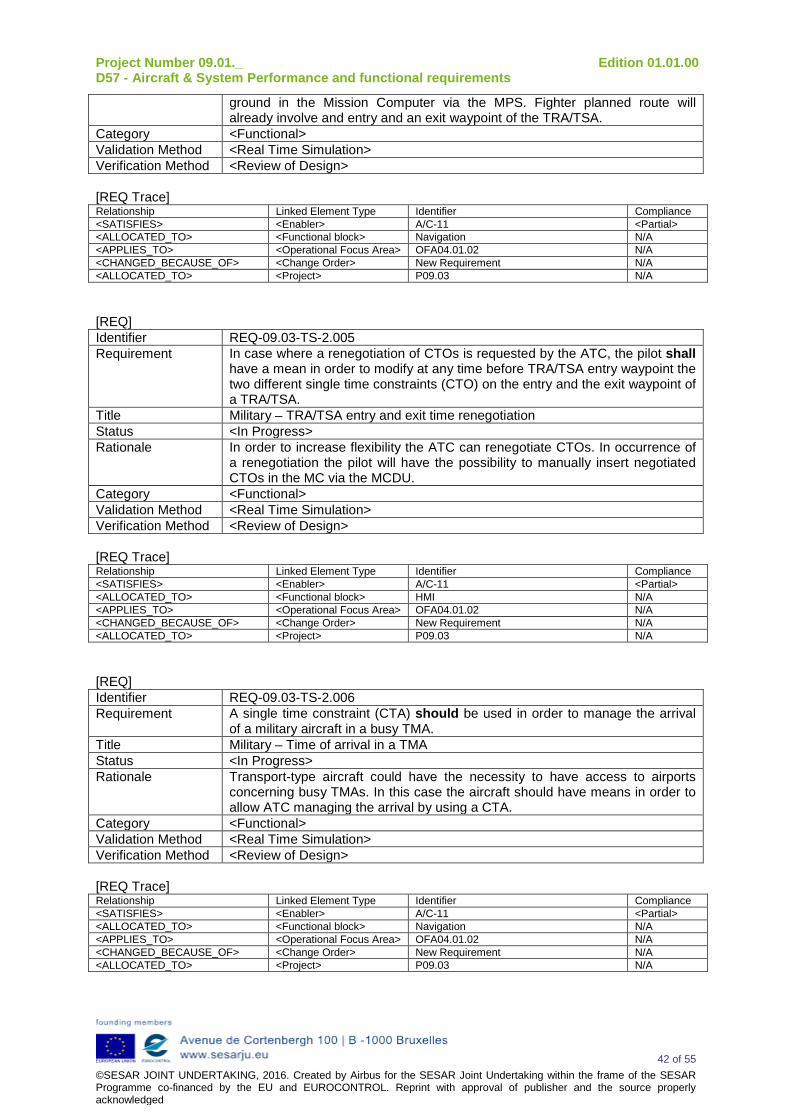
Project Number 09.01._ Edition 01.01.00 D57 - Aircraft & System Performance and functional requirements
42 of 55 ©SESAR JOINT UNDERTAKING, 2016. Created by Airbus for the SESAR Joint Undertaking within the frame of the SESAR Programme co-financed by the EU and EUROCONTROL. Reprint with approval of publisher and the source properly acknowledged
ground in the Mission Computer via the MPS. Fighter planned route will already involve and entry and an exit waypoint of the TRA/TSA.
Category <Functional> Validation Method <Real Time Simulation> Verification Method <Review of Design> [REQ Trace] Relationship Linked Element Type Identifier Compliance <SATISFIES> <Enabler> A/C-11 <Partial> <ALLOCATED_TO> <Functional block> Navigation N/A <APPLIES_TO> <Operational Focus Area> OFA04.01.02 N/A <CHANGED_BECAUSE_OF> <Change Order> New Requirement N/A <ALLOCATED_TO> <Project> P09.03 N/A
[REQ] Identifier REQ-09.03-TS-2.005 Requirement In case where a renegotiation of CTOs is requested by the ATC, the pilot shall
have a mean in order to modify at any time before TRA/TSA entry waypoint the two different single time constraints (CTO) on the entry and the exit waypoint of a TRA/TSA.
Title Military – TRA/TSA entry and exit time renegotiation Status <In Progress> Rationale In order to increase flexibility the ATC can renegotiate CTOs. In occurrence of
a renegotiation the pilot will have the possibility to manually insert negotiated CTOs in the MC via the MCDU.
Category <Functional> Validation Method <Real Time Simulation> Verification Method <Review of Design> [REQ Trace] Relationship Linked Element Type Identifier Compliance <SATISFIES> <Enabler> A/C-11 <Partial> <ALLOCATED_TO> <Functional block> HMI N/A <APPLIES_TO> <Operational Focus Area> OFA04.01.02 N/A <CHANGED_BECAUSE_OF> <Change Order> New Requirement N/A <ALLOCATED_TO> <Project> P09.03 N/A
[REQ] Identifier REQ-09.03-TS-2.006 Requirement A single time constraint (CTA) should be used in order to manage the arrival
of a military aircraft in a busy TMA. Title Military – Time of arrival in a TMA Status <In Progress> Rationale Transport-type aircraft could have the necessity to have access to airports
concerning busy TMAs. In this case the aircraft should have means in order to allow ATC managing the arrival by using a CTA.
Category <Functional> Validation Method <Real Time Simulation> Verification Method <Review of Design> [REQ Trace] Relationship Linked Element Type Identifier Compliance <SATISFIES> <Enabler> A/C-11 <Partial> <ALLOCATED_TO> <Functional block> Navigation N/A <APPLIES_TO> <Operational Focus Area> OFA04.01.02 N/A <CHANGED_BECAUSE_OF> <Change Order> New Requirement N/A <ALLOCATED_TO> <Project> P09.03 N/A
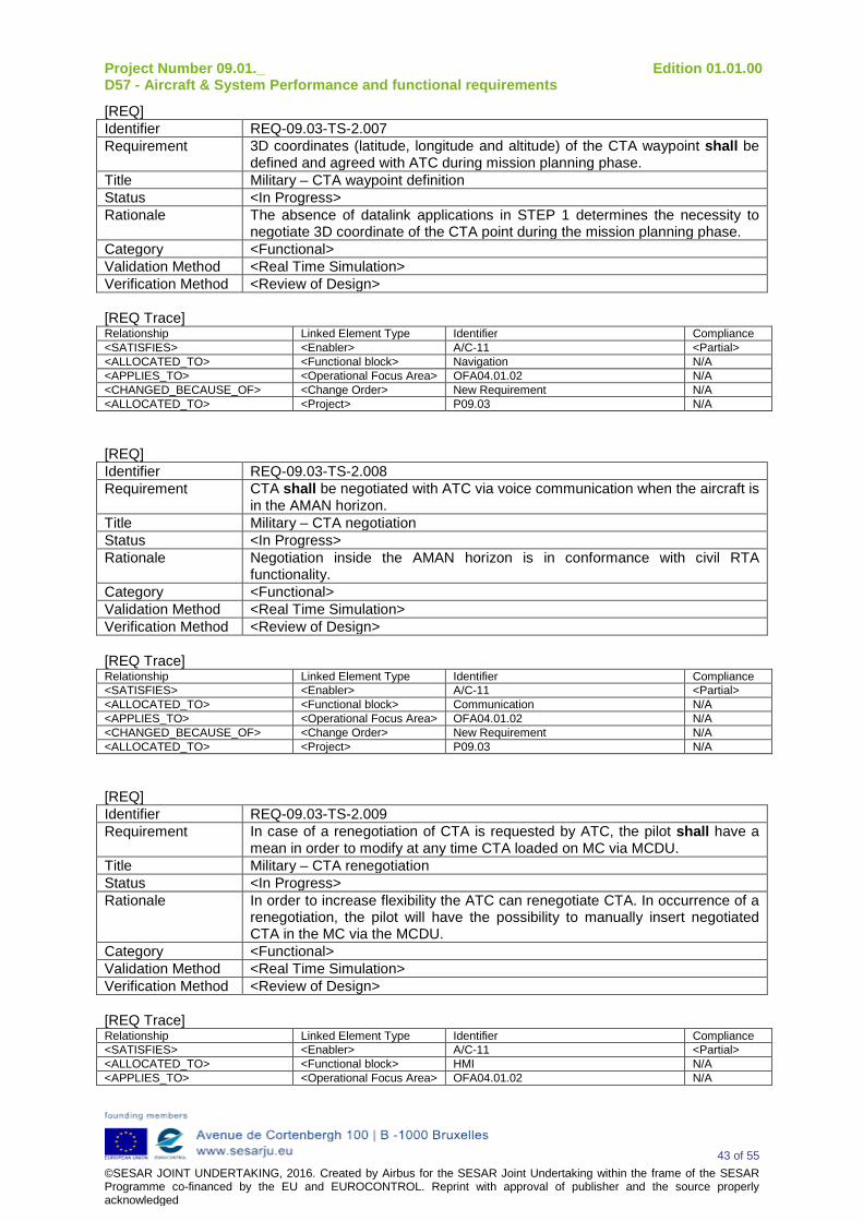
Project Number 09.01._ Edition 01.01.00 D57 - Aircraft & System Performance and functional requirements
43 of 55 ©SESAR JOINT UNDERTAKING, 2016. Created by Airbus for the SESAR Joint Undertaking within the frame of the SESAR Programme co-financed by the EU and EUROCONTROL. Reprint with approval of publisher and the source properly acknowledged
[REQ] Identifier REQ-09.03-TS-2.007 Requirement 3D coordinates (latitude, longitude and altitude) of the CTA waypoint shall be
defined and agreed with ATC during mission planning phase. Title Military – CTA waypoint definition Status <In Progress> Rationale The absence of datalink applications in STEP 1 determines the necessity to
negotiate 3D coordinate of the CTA point during the mission planning phase. Category <Functional> Validation Method <Real Time Simulation> Verification Method <Review of Design> [REQ Trace] Relationship Linked Element Type Identifier Compliance <SATISFIES> <Enabler> A/C-11 <Partial> <ALLOCATED_TO> <Functional block> Navigation N/A <APPLIES_TO> <Operational Focus Area> OFA04.01.02 N/A <CHANGED_BECAUSE_OF> <Change Order> New Requirement N/A <ALLOCATED_TO> <Project> P09.03 N/A
[REQ] Identifier REQ-09.03-TS-2.008 Requirement CTA shall be negotiated with ATC via voice communication when the aircraft is
in the AMAN horizon. Title Military – CTA negotiation Status <In Progress> Rationale Negotiation inside the AMAN horizon is in conformance with civil RTA
functionality. Category <Functional> Validation Method <Real Time Simulation> Verification Method <Review of Design> [REQ Trace] Relationship Linked Element Type Identifier Compliance <SATISFIES> <Enabler> A/C-11 <Partial> <ALLOCATED_TO> <Functional block> Communication N/A <APPLIES_TO> <Operational Focus Area> OFA04.01.02 N/A <CHANGED_BECAUSE_OF> <Change Order> New Requirement N/A <ALLOCATED_TO> <Project> P09.03 N/A
[REQ] Identifier REQ-09.03-TS-2.009 Requirement In case of a renegotiation of CTA is requested by ATC, the pilot shall have a
mean in order to modify at any time CTA loaded on MC via MCDU. Title Military – CTA renegotiation Status <In Progress> Rationale In order to increase flexibility the ATC can renegotiate CTA. In occurrence of a
renegotiation, the pilot will have the possibility to manually insert negotiated CTA in the MC via the MCDU.
Category <Functional> Validation Method <Real Time Simulation> Verification Method <Review of Design> [REQ Trace] Relationship Linked Element Type Identifier Compliance <SATISFIES> <Enabler> A/C-11 <Partial> <ALLOCATED_TO> <Functional block> HMI N/A <APPLIES_TO> <Operational Focus Area> OFA04.01.02 N/A
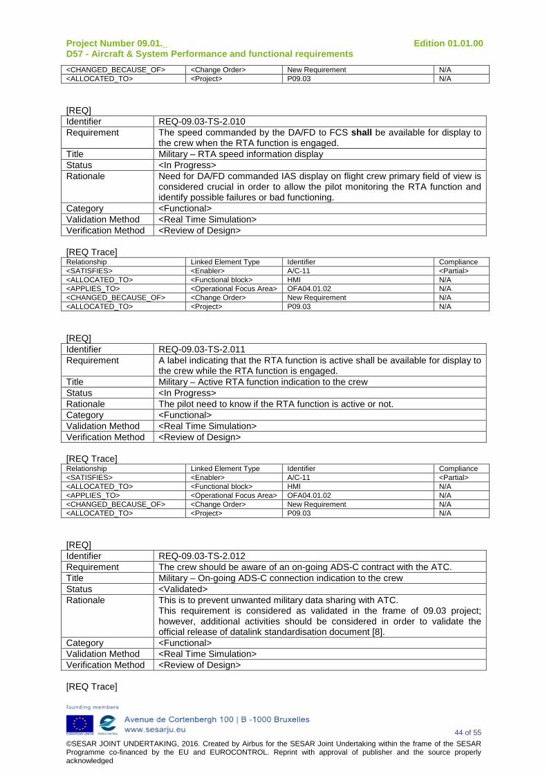
Project Number 09.01._ Edition 01.01.00 D57 - Aircraft & System Performance and functional requirements
44 of 55 ©SESAR JOINT UNDERTAKING, 2016. Created by Airbus for the SESAR Joint Undertaking within the frame of the SESAR Programme co-financed by the EU and EUROCONTROL. Reprint with approval of publisher and the source properly acknowledged
<CHANGED_BECAUSE_OF> <Change Order> New Requirement N/A <ALLOCATED_TO> <Project> P09.03 N/A
[REQ] Identifier REQ-09.03-TS-2.010 Requirement The speed commanded by the DA/FD to FCS shall be available for display to
the crew when the RTA function is engaged. Title Military – RTA speed information display Status <In Progress> Rationale Need for DA/FD commanded IAS display on flight crew primary field of view is
considered crucial in order to allow the pilot monitoring the RTA function and identify possible failures or bad functioning.
Category <Functional> Validation Method <Real Time Simulation> Verification Method <Review of Design> [REQ Trace] Relationship Linked Element Type Identifier Compliance <SATISFIES> <Enabler> A/C-11 <Partial> <ALLOCATED_TO> <Functional block> HMI N/A <APPLIES_TO> <Operational Focus Area> OFA04.01.02 N/A <CHANGED_BECAUSE_OF> <Change Order> New Requirement N/A <ALLOCATED_TO> <Project> P09.03 N/A
[REQ] Identifier REQ-09.03-TS-2.011 Requirement A label indicating that the RTA function is active shall be available for display to
the crew while the RTA function is engaged. Title Military – Active RTA function indication to the crew Status <In Progress> Rationale The pilot need to know if the RTA function is active or not. Category <Functional> Validation Method <Real Time Simulation> Verification Method <Review of Design> [REQ Trace] Relationship Linked Element Type Identifier Compliance <SATISFIES> <Enabler> A/C-11 <Partial> <ALLOCATED_TO> <Functional block> HMI N/A <APPLIES_TO> <Operational Focus Area> OFA04.01.02 N/A <CHANGED_BECAUSE_OF> <Change Order> New Requirement N/A <ALLOCATED_TO> <Project> P09.03 N/A
[REQ] Identifier REQ-09.03-TS-2.012 Requirement The crew should be aware of an on-going ADS-C contract with the ATC. Title Military – On-going ADS-C connection indication to the crew Status <Validated> Rationale This is to prevent unwanted military data sharing with ATC.
This requirement is considered as validated in the frame of 09.03 project; however, additional activities should be considered in order to validate the official release of datalink standardisation document [8].
Category <Functional> Validation Method <Real Time Simulation> Verification Method <Review of Design> [REQ Trace]
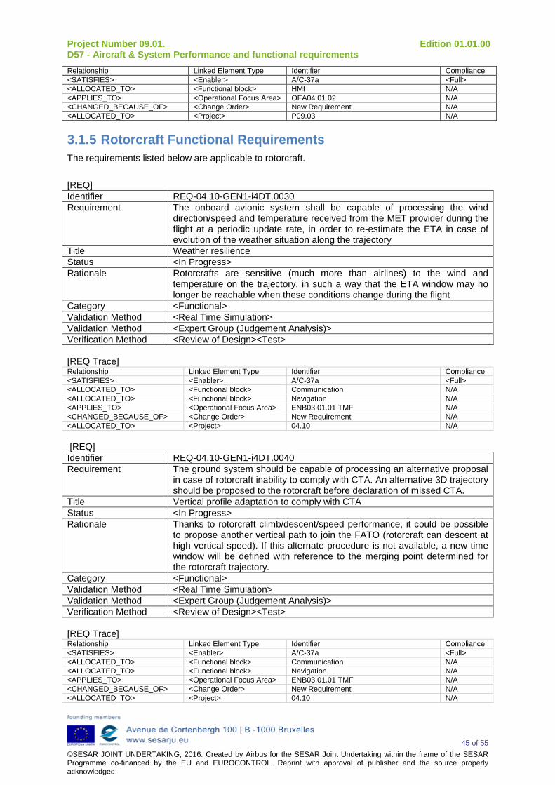
Project Number 09.01._ Edition 01.01.00 D57 - Aircraft & System Performance and functional requirements
45 of 55 ©SESAR JOINT UNDERTAKING, 2016. Created by Airbus for the SESAR Joint Undertaking within the frame of the SESAR Programme co-financed by the EU and EUROCONTROL. Reprint with approval of publisher and the source properly acknowledged
Relationship Linked Element Type Identifier Compliance <SATISFIES> <Enabler> A/C-37a <Full> <ALLOCATED_TO> <Functional block> HMI N/A <APPLIES_TO> <Operational Focus Area> OFA04.01.02 N/A <CHANGED_BECAUSE_OF> <Change Order> New Requirement N/A <ALLOCATED_TO> <Project> P09.03 N/A
3.1.5 Rotorcraft Functional Requirements The requirements listed below are applicable to rotorcraft.
[REQ] Identifier REQ-04.10-GEN1-i4DT.0030 Requirement The onboard avionic system shall be capable of processing the wind
direction/speed and temperature received from the MET provider during the flight at a periodic update rate, in order to re-estimate the ETA in case of evolution of the weather situation along the trajectory
Title Weather resilience Status <In Progress> Rationale Rotorcrafts are sensitive (much more than airlines) to the wind and
temperature on the trajectory, in such a way that the ETA window may no longer be reachable when these conditions change during the flight
Category <Functional> Validation Method <Real Time Simulation> Validation Method <Expert Group (Judgement Analysis)> Verification Method <Review of Design><Test> [REQ Trace] Relationship Linked Element Type Identifier Compliance <SATISFIES> <Enabler> A/C-37a <Full> <ALLOCATED_TO> <Functional block> Communication N/A <ALLOCATED_TO> <Functional block> Navigation N/A <APPLIES_TO> <Operational Focus Area> ENB03.01.01 TMF N/A <CHANGED_BECAUSE_OF> <Change Order> New Requirement N/A <ALLOCATED_TO> <Project> 04.10 N/A [REQ] Identifier REQ-04.10-GEN1-i4DT.0040 Requirement The ground system should be capable of processing an alternative proposal
in case of rotorcraft inability to comply with CTA. An alternative 3D trajectory should be proposed to the rotorcraft before declaration of missed CTA.
Title Vertical profile adaptation to comply with CTA Status <In Progress> Rationale Thanks to rotorcraft climb/descent/speed performance, it could be possible
to propose another vertical path to join the FATO (rotorcraft can descent at high vertical speed). If this alternate procedure is not available, a new time window will be defined with reference to the merging point determined for the rotorcraft trajectory.
Category <Functional> Validation Method <Real Time Simulation> Validation Method <Expert Group (Judgement Analysis)> Verification Method <Review of Design><Test> [REQ Trace] Relationship Linked Element Type Identifier Compliance <SATISFIES> <Enabler> A/C-37a <Full> <ALLOCATED_TO> <Functional block> Communication N/A <ALLOCATED_TO> <Functional block> Navigation N/A <APPLIES_TO> <Operational Focus Area> ENB03.01.01 TMF N/A <CHANGED_BECAUSE_OF> <Change Order> New Requirement N/A <ALLOCATED_TO> <Project> 04.10 N/A
Project Number 09.01._ Edition 01.01.00 D57 - Aircraft & System Performance and functional requirements
46 of 55 ©SESAR JOINT UNDERTAKING, 2016. Created by Airbus for the SESAR Joint Undertaking within the frame of the SESAR Programme co-financed by the EU and EUROCONTROL. Reprint with approval of publisher and the source properly acknowledged
3.2 Adaptability N/A
3.3 Performance Characteristics Performance requirements are integrated within functional requirements. Dedicated performance related requirements are:
- REQ-09.01-TS-0.201
- REQ-09.01-TS-1.225
- REQ-09.01-TS-1.282
- REQ-09.01-TS-1.315
- REQ-09.01-TS-1.383
3.4 Safety & Security
3.4.1 Security Requirements In the frame of SESAR 1 P09.01 activities and the development of Initial 4D function, no work has been conducted on this topic. In this condition, traceability to the following P05.06.01 SPR [13] requirements is not performed in this document:
- REQ-05.06.01-Step 1SPR IT3-SEC1.0003
- REQ-05.06.01-Step 1SPR IT3-SEC1.0004
3.4.2 Safety Requirements The safety requirements below are extracted from the P05.06.01 SPR [13].
[REQ] Identifier REQ-09.01-TS-2.004 Requirement The probability of FMS failing to detect and alert on unachievable RTA shall not
exceed 2.0E-04 per Flight Hour. Title Probability of FMA failing to detect and alert on unachievable RTA Status <In progress> Rationale Extracted from P05.06.01 SPR [13].
No quantitative analysis has been performed in the scope of P09.01 project to demonstrate the probability defined in SPR. Further analysis must be performed to verify that the aircraft definition and implementation is in line with this requirement.
Category <Safety> Validation Method <Analytical Modelling> Verification Method <Review of Design> [REQ Trace] Relationship Linked Element Type Identifier Compliance <SATISFIES> <Enabler> A/C-11 <Full> <SATISFIES> <ATMS Requirement> REQ-05.06.01-Step 1SPR IT3-SAF1.0105 <Full> <ALLOCATED_TO> <Functional block> Navigation N/A <APPLIES_TO> <Operational Focus Area> OFA04.01.02 N/A <CHANGED_BECAUSE_OF> <Change Order> New Requirement N/A <ALLOCATED_TO> <Project> P09.01 N/A
Project Number 09.01._ Edition 01.01.00 D57 - Aircraft & System Performance and functional requirements
47 of 55 ©SESAR JOINT UNDERTAKING, 2016. Created by Airbus for the SESAR Joint Undertaking within the frame of the SESAR Programme co-financed by the EU and EUROCONTROL. Reprint with approval of publisher and the source properly acknowledged
[REQ] Identifier REQ-09.01-TS-2.005 Requirement The probability of non-detection by aircraft monitoring of RTA un-achievability
shall not exceed 2.0E-04 per Flight Hour. Title Probability of non-detection by aircraft monitoring of RTA un-achievability Status <In progress> Rationale Extracted from P05.06.01 SPR [13].
No quantitative analysis has been performed in the scope of P09.01 project to demonstrate the probability defined in SPR. Further analysis must be performed to verify that the aircraft definition and implementation is in line with this requirement.
Category <Safety> Validation Method <Analytical Modelling> Verification Method <Review of Design> [REQ Trace] Relationship Linked Element Type Identifier Compliance <SATISFIES> <Enabler> A/C-11 <Full> <SATISFIES> <ATMS Requirement> REQ-05.06.01-Step 1SPR IT3-SAF1.0107 <Full> <ALLOCATED_TO> <Functional block> Navigation N/A <APPLIES_TO> <Operational Focus Area> OFA04.01.02 N/A <CHANGED_BECAUSE_OF> <Change Order> New Requirement N/A <ALLOCATED_TO> <Project> P09.01 N/A [REQ] Identifier REQ-09.01-TS-2.006 Requirement The probability that an RTA becomes not met due to aircraft failures shall not
exceed 1.0E-03 per Flight Hour. Title Probability that an RTA becomes not met due to aircraft failures Status <In progress> Rationale Extracted from P05.06.01 SPR [13].
No quantitative analysis has been performed in the scope of P09.01 project to demonstrate the probability defined in SPR. Further analysis must be performed to verify that the aircraft definition and implementation is in line with this requirement.
Category <Safety> Validation Method <Analytical Modelling> Verification Method <Review of Design> [REQ Trace] Relationship Linked Element Type Identifier Compliance <SATISFIES> <Enabler> A/C-11 <Full> <SATISFIES> <ATMS Requirement> REQ-05.06.01-Step 1SPR IT3-SAF1.0108 <Full> <ALLOCATED_TO> <Functional block> Navigation N/A <APPLIES_TO> <Operational Focus Area> OFA04.01.02 N/A <CHANGED_BECAUSE_OF> <Change Order> New Requirement N/A <ALLOCATED_TO> <Project> P09.01 N/A [REQ] Identifier REQ-09.01-TS-2.007 Requirement The probability of erroneous EPP message downlink shall not exceed 1.3E-04
per Flight Hour. Title Probability of erroneous EPP message downlink Status <In progress> Rationale Extracted from P05.06.01 SPR [13].
No quantitative analysis has been performed in the scope of P09.01 project to demonstrate the probability defined in SPR. Further analysis must be performed to verify that the aircraft definition and implementation is in line with this requirement.
Project Number 09.01._ Edition 01.01.00 D57 - Aircraft & System Performance and functional requirements
48 of 55 ©SESAR JOINT UNDERTAKING, 2016. Created by Airbus for the SESAR Joint Undertaking within the frame of the SESAR Programme co-financed by the EU and EUROCONTROL. Reprint with approval of publisher and the source properly acknowledged
Category <Safety> Validation Method <Analytical Modelling> Verification Method <Review of Design> [REQ Trace] Relationship Linked Element Type Identifier Compliance <SATISFIES> <Enabler> A/C-37a <Full> <SATISFIES> <ATMS Requirement> REQ-05.06.01-Step 1SPR IT3-SAF1.0135 <Full> <ALLOCATED_TO> <Functional block> Communication N/A <ALLOCATED_TO> <Functional block> Navigation N/A <APPLIES_TO> <Operational Focus Area> OFA04.01.02 N/A <CHANGED_BECAUSE_OF> <Change Order> New Requirement N/A <ALLOCATED_TO> <Project> P09.01 N/A
3.5 Maintainability N/A
3.6 Reliability Reliability requirements are integrated within functional requirements in section 3.1.
3.7 Functional block Internal Data Requirements N/A
3.8 Design and Construction Constraints N/A
3.9 Functional block Interface Requirements Refer to functional requirements in section 3.1 and in P09.01 D58 “Interface requirements between the aircraft and the ATC systems” [11] for further details.
Project Number 09.01._ Edition 01.01.00 D57 - Aircraft & System Performance and functional requirements
49 of 55 ©SESAR JOINT UNDERTAKING, 2016. Created by Airbus for the SESAR Joint Undertaking within the frame of the SESAR Programme co-financed by the EU and EUROCONTROL. Reprint with approval of publisher and the source properly acknowledged
4 Assumptions Remaining open points in the CTA concept definition have been further explored by P05.06.01 Expert Group and are available in the report integrated as an Appendix of P05.06.01 Step 1 OSED Final [12].
Project Number 09.01._ Edition 01.01.00 D57 - Aircraft & System Performance and functional requirements
50 of 55 ©SESAR JOINT UNDERTAKING, 2016. Created by Airbus for the SESAR Joint Undertaking within the frame of the SESAR Programme co-financed by the EU and EUROCONTROL. Reprint with approval of publisher and the source properly acknowledged
5 References [1] Template Toolbox 03.00.00
https://extranet.sesarju.eu/Programme%20Library/SESAR%20Template%20Toolbox.dot
[2] Requirements and V&V Guidelines 03.00.00 https://extranet.sesarju.eu/Programme%20Library/Requirements%20and%20VV%20Guidelines.doc
[3] Templates and Toolbox User Manual 03.00.00 https://extranet.sesarju.eu/Programme%20Library/Templates%20and%20Toolbox%20User%20Manual.doc
[4] EUROCONTROL ATM Lexicon https://extranet.eurocontrol.int/http://atmlexicon.eurocontrol.int/en/index.php/SESAR
[5] B.04.03 D128 ADD SESAR 1 edition
[6] IEEE / MIL Standards
[7] WG78/SC214 Safety and Performances – version H
[8] EUROCAE ED-228A Safety and Performance Requirements Standard for Baseline 2 ATS Data Communications (Baseline 2 SPR Standard)
[9] RTCA DO-236C Change 1 Minimum Aviation System Performance Standards: Required Navigation Performance for Area Navigation
[10] EUROCAE ED-75D Minimum Aviation System Performance Standards: Required Navigation Performance for Area Navigation
[11] 09.01 D58 Interface requirements between the Aircraft and the ATC systems
[12] 05.06.01 D84 Step 1 – Fully Validate SPR which includes final OSED
[13] 05.06.01 D84 Step 1 – Fully Validated SPR
[14] 05.06.01 D85 Step 1 – Fully Validated Interop
[15] 09.49-D03-002-Batch 1 & 2 - Consolidated Functional Airborne Architecture – Version 2
[16] ARINC 702A-4 Advanced flight management computer system
5.1 Use of copyright / patent material /classified material
5.1.1 Classified Material N/A

Project Number 09.01._ Edition 01.01.00 D57 - Aircraft & System Performance and functional requirements
51 of 55 ©SESAR JOINT UNDERTAKING, 2016. Created by Airbus for the SESAR Joint Undertaking within the frame of the SESAR Programme co-financed by the EU and EUROCONTROL. Reprint with approval of publisher and the source properly acknowledged
Project Number 09.01._ Edition 01.01.00 D57 - Aircraft & System Performance and functional requirements
52 of 55 ©SESAR JOINT UNDERTAKING, 2016. Created by Airbus for the SESAR Joint Undertaking within the frame of the SESAR Programme co-financed by the EU and EUROCONTROL. Reprint with approval of publisher and the source properly acknowledged
Appendix A Rotorcraft operational requirements The following requirements have been created as they are specific to rotorcraft i4D operations, and they have no dedicated requirements in the Aircraft i4D. [REQ] Identifier REQ-04.10-GEN1-i4DT.0010 Requirement A rotorcraft merging point shall be defined according to rotorcraft
performance, at a suitable location within the controlled airspace Title Rotorcraft merging point Status <In Progress> Rationale For a rotorcraft to converge into the IFR traffic flows, an appropriate merging
point has to be defined to enter the controlled airspace. This merging point shall be defined taking into account the rotorcraft performance, especially due to their condition of flying at lower (en-route) altitudes than fixed wings.
Category <Operational> Validation Method <Real Time Simulation> Verification Method <Review of Design> [REQ Trace] Relationship Linked Element Type Identifier Compliance <SATISFIES> <Enabler> A/C-37a <Full> <ALLOCATED_TO> <Functional block> Communication N/A <ALLOCATED_TO> <Functional block> Navigation N/A <APPLIES_TO> <Operational Focus Area> ENB03.01.01 TMF N/A <CHANGED_BECAUSE_OF> <Change Order> New Requirement N/A <ALLOCATED_TO> <Project> 04.10 N/A [REQ] Identifier REQ-04.10-GEN1-i4DT.0011 Requirement A rotorcraft metering point shall be defined into the IFR airspace after the
rotorcraft merging point, point on which an RTA time constraint has to be set. The metering point shall be either the IAF, or the IF, or the FAF, depending on the airspace density / complexity
Title Rotorcraft metering point Status <In Progress> Rationale The metering point is a constraint point, i.e. a merging point, with a target
time of arrival assigned to that point. The calculation of the target time shall take into account the performance of rotorcraft operations (e.g. descent/ascent rate, speed) and be defined specifically for rotorcrafts. If the approach is SNI, the metering point can be located at the FAF (if the MAPt is separated). If the approach is non-SNI, the metering point cannot be located inside the interfering area because temporal separation has to be performed. In that case, the metering point has to be located just before this area.
Category <Operational> Validation Method <Real Time Simulation> Verification Method <Review of Design> [REQ Trace] Relationship Linked Element Type Identifier Compliance <SATISFIES> <Enabler> A/C-37a <Full> <ALLOCATED_TO> <Functional block> Communication N/A <ALLOCATED_TO> <Functional block> Navigation N/A <APPLIES_TO> <Operational Focus Area> ENB03.01.01 TMF N/A <CHANGED_BECAUSE_OF> <Change Order> New Requirement N/A <ALLOCATED_TO> <Project> 04.10 N/A [REQ] Identifier REQ-04.10-GEN1-i4DT.0020
Project Number 09.01._ Edition 01.01.00 D57 - Aircraft & System Performance and functional requirements
53 of 55 ©SESAR JOINT UNDERTAKING, 2016. Created by Airbus for the SESAR Joint Undertaking within the frame of the SESAR Programme co-financed by the EU and EUROCONTROL. Reprint with approval of publisher and the source properly acknowledged
Requirement During the transition from VFR into IFR, a time window shall be defined specifying the earliest point in time in which the rotorcraft is required to submit its intended business trajectory to ATC and the latest point in time to do so.
Title Time window for RBT submission when transitioning from VFR to IFR Status <In Progress> Rationale The time windows shall be defined with reference to the merging point
determined for the rotorcraft to enter IFR airspace (REQ-04.10-i4D.0010) and taking into account the metering time assigned to that merging point (REQ-04.10-i4D.0011) as well as comply to the i4D and CTA requirements.
Category <Operational> Validation Method <Real Time Simulation> Validation Method <Expert Group (Judgement Analysis)> Verification Method <Test> [REQ Trace] Relationship Linked Element Type Identifier Compliance <SATISFIES> <Enabler> A/C-37a <Full> <ALLOCATED_TO> <Functional block> Communication N/A <ALLOCATED_TO> <Functional block> Navigation N/A <APPLIES_TO> <Operational Focus Area> ENB03.01.01 TMF N/A <CHANGED_BECAUSE_OF> <Change Order> New Requirement N/A <ALLOCATED_TO> <Project> 04.10 N/A [REQ] Identifier REQ-04.10-GEN1-i4DT.0050 Requirement In case of FATO non used for SNI operation, rotorcraft approach procedure
to be used for i4D, shall optimize the strategic separation between A/C and rotorcraft at least before the FAF for rotorcraft.
Title Strategic separation between aircraft and rotorcraft arrival path with FATO not used with SNI operation.
Status <In Progress> Rationale Limitation of aircraft and rotorcraft flow management constraints, limitation
of airspace constraint. Category <Operational> Validation Method <Real Time Simulation> Verification Method <Review of Design> [REQ Trace] Relationship Linked Element Type Identifier Compliance <SATISFIES> <Enabler> A/C-37a <Full> <ALLOCATED_TO> <Functional block> Communication N/A <ALLOCATED_TO> <Functional block> Navigation N/A <APPLIES_TO> <Operational Focus Area> ENB03.01.01 TMF N/A <CHANGED_BECAUSE_OF> <Change Order> New Requirement N/A <ALLOCATED_TO> <Project> 04.10 N/A [REQ] Identifier REQ-04.10-GEN1-i4DT.0070 Requirement The operational procedure for i4D integration in a TMA shall define the
transition procedure which addresses the ATCO / PILOT communication when it turns from datalink to voice.
Title Transition procedure applied in a TMA when the ATCO / PILOT communication turns from datalink to voice
Status <In Progress> Rationale Adherence to the agreed concept Category <Operational> Validation Method <Real Time Simulation> Verification Method <Test> [REQ Trace]
Project Number 09.01._ Edition 01.01.00 D57 - Aircraft & System Performance and functional requirements
54 of 55 ©SESAR JOINT UNDERTAKING, 2016. Created by Airbus for the SESAR Joint Undertaking within the frame of the SESAR Programme co-financed by the EU and EUROCONTROL. Reprint with approval of publisher and the source properly acknowledged
Relationship Linked Element Type Identifier Compliance <SATISFIES> <Enabler> A/C-37a <Full> <ALLOCATED_TO> <Functional block> Communication N/A <ALLOCATED_TO> <Functional block> Navigation N/A <APPLIES_TO> <Operational Focus Area> ENB03.01.01 TMF N/A <CHANGED_BECAUSE_OF> <Change Order> New Requirement N/A <ALLOCATED_TO> <Project> 04.10 N/A [REQ] Identifier REQ-04.10-GEN1-i4DT.0080 Requirement The AMAN/DMAN algorithms shall be able to take into account
simultaneous aircraft and rotorcraft streams, and specifically i4D rotorcraft. Title The design of AMAN/DMAN tool capable of supporting the ATCO when
managing a sequence which includes simultaneous aircraft and rotorcraft streams
Status <In Progress> Rationale Adherence to the agreed concept Category <Operational> Validation Method <Real Time Simulation> Verification Method <Review of Design> [REQ Trace] Relationship Linked Element Type Identifier Compliance <SATISFIES> <Enabler> A/C-37a <Full> <ALLOCATED_TO> <Functional block> Communication N/A <ALLOCATED_TO> <Functional block> Navigation N/A <APPLIES_TO> <Operational Focus Area> ENB03.01.01 TMF N/A <CHANGED_BECAUSE_OF> <Change Order> New Requirement N/A <ALLOCATED_TO> <Project> 04.10 N/A [REQ] Identifier REQ-04.10-GEN1-i4DT.0081 Requirement The AMAN/DMAN HMI shall be able to propose information in order to
support the ATCO when managing simultaneous rotorcraft and aircraft streams, and specifically i4D rotorcraft.
Title The use of AMAN/DMAN tool capable of supporting the ATCO when managing a sequence which includes simultaneous aircraft and rotorcraft streams.
Status <In Progress> Rationale Adherence to the agreed concept Category <Operational> Validation Method <Real Time Simulation> Verification Method <Review of Design> [REQ Trace] Relationship Linked Element Type Identifier Compliance <SATISFIES> <Enabler> A/C-37a <Full> <ALLOCATED_TO> <Functional block> Communication N/A <ALLOCATED_TO> <Functional block> Navigation N/A <APPLIES_TO> <Operational Focus Area> ENB03.01.01 TMF N/A <CHANGED_BECAUSE_OF> <Change Order> New Requirement N/A <ALLOCATED_TO> <Project> 04.10 N/A

Project Number 09.01._ Edition 01.01.00 D57 - Aircraft & System Performance and functional requirements
55 of 55 ©SESAR JOINT UNDERTAKING, 2016. Created by Airbus for the SESAR Joint Undertaking within the frame of the SESAR Programme co-financed by the EU and EUROCONTROL. Reprint with approval of publisher and the source properly acknowledged
-END OF DOCUMENT-


![IEC 61508 Assessment - exida€¦ · IEC 61508 Functional Safety Assessment ... [D38] QP 01; Rev 03; 4/29/2009 ... RP Approved Vendor; 7/6/2012 Approved Vendor List [D57] ...](https://static.fdocuments.net/doc/165x107/5b8675187f8b9a162d8d0076/iec-61508-assessment-iec-61508-functional-safety-assessment-d38-qp-01.jpg)
